EP2626294A2 - Low profile jettisonable door system - Google Patents
Low profile jettisonable door system Download PDFInfo
- Publication number
- EP2626294A2 EP2626294A2 EP20130153927 EP13153927A EP2626294A2 EP 2626294 A2 EP2626294 A2 EP 2626294A2 EP 20130153927 EP20130153927 EP 20130153927 EP 13153927 A EP13153927 A EP 13153927A EP 2626294 A2 EP2626294 A2 EP 2626294A2
- Authority
- EP
- European Patent Office
- Prior art keywords
- pin
- door system
- jettisonable
- hinge
- jettisonable door
- Prior art date
- Legal status (The legal status is an assumption and is not a legal conclusion. Google has not performed a legal analysis and makes no representation as to the accuracy of the status listed.)
- Granted
Links
Images


Classifications
-
- B—PERFORMING OPERATIONS; TRANSPORTING
- B64—AIRCRAFT; AVIATION; COSMONAUTICS
- B64C—AEROPLANES; HELICOPTERS
- B64C1/00—Fuselages; Constructional features common to fuselages, wings, stabilising surfaces or the like
- B64C1/14—Windows; Doors; Hatch covers or access panels; Surrounding frame structures; Canopies; Windscreens accessories therefor, e.g. pressure sensors, water deflectors, hinges, seals, handles, latches, windscreen wipers
- B64C1/1407—Doors; surrounding frames
-
- B—PERFORMING OPERATIONS; TRANSPORTING
- B64—AIRCRAFT; AVIATION; COSMONAUTICS
- B64C—AEROPLANES; HELICOPTERS
- B64C1/00—Fuselages; Constructional features common to fuselages, wings, stabilising surfaces or the like
- B64C1/32—Severable or jettisonable parts of fuselage facilitating emergency escape
-
- B—PERFORMING OPERATIONS; TRANSPORTING
- B64—AIRCRAFT; AVIATION; COSMONAUTICS
- B64C—AEROPLANES; HELICOPTERS
- B64C27/00—Rotorcraft; Rotors peculiar thereto
- B64C27/04—Helicopters
Definitions
- the present disclosure relates to a jettisonable door system for an aircraft. More specifically, the present disclosure relates to a jettisonable door release mechanism for a rotorcraft.
- the devices, members, apparatuses, etc. described herein may be positioned in any desired orientation.
- the use of terms such as “above,” “below,” “upper,” “lower,” or other like terms to describe a spatial relationship between various components or to describe the spatial orientation of aspects of such components should be understood to describe a relative relationship between the components or a spatial orientation of aspects of such components, respectively, as the device described herein may be oriented in any desired direction.
- the embodiments of the present disclosure include an efficient, compact, and aesthetic jettisonable door system.
- the present disclosure further includes a method of egressing a rotorcraft.
- One unique feature of the system of the present application is the use of a quarter-turn, cam-like action to secure/release the hinges of the door.
- the system is configured so that the entire door is removed from the airframe during an emergency egress event.
- a jettisonable door system 101 is illustrated on a rotorcraft 801 (shown in Figure 10 ).
- a rotorcraft 801 is illustrated.
- Rotorcraft 801 has a rotor system 803 with a plurality of main rotor blades 811.
- Rotorcraft 801 further includes an airframe 103, landing gear 807, a tail member 809, and tail rotor blades 813.
- An engine 815 supplies torque to a main rotor mast 817 and a tail rotor drive shaft 819, for the rotating of main rotor blades 811 and tail rotor blades 813, respectively.
- each main rotor blade 811 can be selectively controlled in order to selectively control direction, thrust, and lift of rotorcraft 801. Further, the pitch of tail rotor blades 813 can be selectively controlled in order to selectively control yaw of rotorcraft 801.
- rotorcraft 801 is merely exemplary of one type of aircraft for which jettisonable door system 101 can be implemented.
- a conventional fixed wing aircraft is another example of an aircraft for which jettisonable door system 101 can be implemented.
- the implementation of jettisonable door system 101 is not limited to rotorcraft and fixed wing aircraft, as other aircraft types may also utilize jettisonable door system 101.
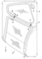
- jettisonable door system 101 includes an upper hinge assembly 107 and a lower hinge assembly 109, which both hingedly couple door 111 to airframe 103.
- Jettisonable door system 101 is functional with the regular door latch system.
- the pilot When a pilot seeks to make an emergency egress from a rotorcraft, such as rotorcraft 801, the pilot simply turns the emergency egress handle 105 with a rotational turn.
- the amount of rotation is approximately 1/4 of a full rotation (90 degrees); however, it should be appreciated that other degrees of rotation can be utilized.
- the rotational turn of emergency egress handle 105 causes door 111 to release from the portions of upper hinge assembly 107 and lower hinge assembly 109 that are fixedly coupled to airframe 103. Further, the rotational turn of emergency egress handle 105 simultaneously causes the actuation and release of the regular door latch system associated with a door handle 121.
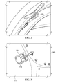
- lower hinge assembly 109 is illustrated in further detail. Figures 4A and 4B depict lower hinge assembly 109 in the locked position, while Figures 5A and 5B depict lower hinge assembly 109 in an unlocked position. Figures 4A and 5A are interior views of lower hinge assembly 109 with a portion of the door structure removed for clarity.
- FIGS 4B and 5B are exterior views of lower hinge assembly 109 with cover 113 removed for clarity.
- Lower hinge assembly 109 can include an outboard plate 123 having an aperture for a pin 125 located therethrough. Outboard plate 123 is fixed to the structure of door 111. In the illustrated embodiment, outboard plate 123 is attached to an exterior surface of door 111.
- Lower hinge assembly 109 can include an inboard plate 127 having an aperture for pin 125 located therethrough. Inboard plate 127 is mounted in an interior portion of door 111.
- the outboard portion of pin 125 has a cam member 115 extending in an approximately rectangular shape, the outboard portion being approximately perpendicular to the axial centerline of pin 125.
- the inboard portion of pin 125 has an adapter 131 coupled thereto.
- the adapter 131 is configured for receiving a lower wire rope 135 that is operably coupled to the mechanism of door handle 121 for releasing the conventional door latch. As such, an actuation of emergency egress handle 105 also actuates the conventional door latch through a translation of lower wire rope 135. Adapter 131 is also configured for receiving an upper wire rope 133 that is operably coupled to emergency egress handle 105 such that an turning actuation of emergency egress handle 105 causes pin 125 to rotate. In the illustrated embodiment, adapter 131 1 is lobe shaped so that the attachment locations of lower wire rope 135 and upper wire rope 133 are offset from the rotational axis of pin 125.
- a lower hinge 137 is hingedly coupled to airframe 103 at an axis 139 at a forward portion of lower hinge 137.
- lower hinge 137 is secured to outboard plate 123 by the position of cam member 115 of pin 125.
- Lower hinge 137 includes a body portion having a recessed portion 117 that not only secures lower hinge 137 to outboard plate 123, but also provides a rotational guide for cam member 115 to rotate therewithin. It should be appreciated that in an alternative embodiment, recessed portion 117 is absent such that cam member 115 resides against an external surface of lower hinge 137; however, recessed portion 117 can be advantageous because of resulting aerodynamic efficiency of cover 113 (shown in Figure 3 ) being flush with outboard plate 123.
- Lower hinge 137 also includes an aperture 119 that provides clearance for cam member 115.
- Aperture 119 has geometry similar to the geometry of cam member 115, and also provides a clearance gap so that lower hinge 137 can separate from door 111 by traversal of cam member 115 through aperture 119 when pin 125 is rotated to cause geometric alignment of cam member 115 with aperture 119.
- FIGS. 6A, 6B , 7A, 7B , and 9 upper hinge assembly 107 is illustrated in further detail.
- Figures 6A and 6B depict upper hinge assembly 107 in the locked position, while Figures 7A and 7B depict upper hinge assembly 107 in an unlocked position.
- Figures 6A and 7A are interior views of upper hinge assembly 107 with a portion of the door structure removed for clarity.
- Figures 6B and 7B are exterior views of upper hinge assembly 107 with cover 113 removed for clarity.
- Upper hinge assembly 107 can include an outboard plate 141 having an aperture for a pin 143 located therethrough. Outboard plate 141 is fixed to the structure of door 111. In the illustrated embodiment, outboard plate 141 is attached to an exterior surface of door 111.
- Upper hinge assembly 107 can include an inboard bracket 145 having an aperture for pin 143 located therethrough.
- Inboard bracket 145 is mounted in an interior portion of door 111.
- the outboard portion of pin 143 has a cam member 147 extending in an approximately rectangular shape, the outboard portion being approximately perpendicular to the axial centerline of pin 143.
- the inboard portion of pin 143 is coupled to handle 105, with handle 105 being exposed to the interior of the cabin of the aircraft.
- the handle 105 is configured for receiving an upper portion of upper wire rope 133.
- the upper wire rope 133 is also operably coupled to adapter 131 such that an actuation of handle 105 not only rotates pin 143 of upper hinge assembly 107, but also pin 125 of lower hinge assembly 109.
- upper wire rope 133 is coupled to a portion of handle 105 that is offset from the rotational axis of pin 143.
- An upper hinge 149 is hingedly coupled to airframe 103 at an axis 151 at a forward portion upper hinge 149.
- upper hinge 149 is secured to outboard plate 141 by the position of cam member 147 of pin 143.
- Upper hinge 149 includes a body portion having a recessed portion 153 that not only secures upper hinge 149 to outboard plate 141, but also provides a rotational guide for cam member 147 to rotate therewithin. It should be appreciated that in an alternative embodiment, recessed portion 153 is absent such that cam member 147 resides against an external surface of upper hinge 149; however, recessed portion 153 can be advantageous because of resulting aerodynamic efficiency of cover 155 (shown in Figure 1 ) being flush with outboard plate 141.
- Upper hinge 149 also includes an aperture 157 that provides clearance for cam member 147.
- Aperture 157 has geometry similar to the geometry of cam member 147, and also provides a clearance gap so that upper hinge 149 can separate from door 111 by traversal of cam member 147 through aperture 157 when pin 143 is rotated to cause geometric alignment of cam member 147 with aperture 157.
- FIG. 8 a dynamic illustration of the release of door 111 from the aircraft at upper hinge assembly 107 is depicted. It should be appreciated that the release of door 111 from the aircraft at lower hinge assembly 109 is substantially similar.
- an actuation of handle 105 causes pins 125 and 143 to rotate, thereby causing cam members 115 and 147 to align with apertures 119 and 157, respectively.
- handle 105 is operably associated with the regular door latch system of handle 121, the rotational turn of emergency egress handle 105 simultaneously causes the actuation and release of the regular door latch system.
- the pilot can then push on the door 111 so that cam members 115 and 147 are translated through apertures 119 and 157, respectively, as the outward translation of door 111 pushes against upper hinge 149 and lower hinge 137, thereby causing each hinge to rotates about axes 151 and 139, respectively, until each hinge 149 and 137 are clear from the outward movement of door 111.
- the pilot or other aircraft occupant is free to egress the aircraft without the impediment of door 111.
- Jettisonable door system 101 provides significant advantages of conventional systems. For example, the release mechanisms in jettisonable door system 101 are much simpler in operation over conventional systems, and provide more reliability with less adjustment and maintenance. Further, the release mechanisms in jettisonable door system 101 are much smaller than conventional systems, which allow it to be more concealed and made much more aesthetically pleasing. Further, the quarter turn mechanism in its simplicity allows the pins to be constructed in such a manner as to handle the aerodynamic and other loads on the door without large, obtrusive structural elements. Further, the cam action of the mechanism allows it to be very solid without potential for wear, as it is as strong as the original door. Further, the jettisonable door system 101 is easily retrofitable onto an existing aircraft.
Landscapes
- Engineering & Computer Science (AREA)
- Mechanical Engineering (AREA)
- Aviation & Aerospace Engineering (AREA)
- Hinges (AREA)
- Vehicle Step Arrangements And Article Storage (AREA)
- Wing Frames And Configurations (AREA)
- Bridges Or Land Bridges (AREA)
Abstract
Description
- The present disclosure relates to a jettisonable door system for an aircraft. More specifically, the present disclosure relates to a jettisonable door release mechanism for a rotorcraft.
- It can be desirable for a pilot to quickly and efficiently egress an aircraft in an emergency situation. For example, during a controlled ditch of an aircraft over a body of water, it is desirable for the pilot to efficiently remove the door from the airframe so the pilot can timely egress the aircraft.
- There is a need for an efficient jettisonable door system for a rotorcraft.
- The novel features believed characteristic of the embodiments of the present disclosure are set forth in the appended claims. However, the embodiments themselves, as well as a preferred mode of use, and further objectives and advantages thereof, will best be understood by reference to the following detailed description when read in conjunction with the accompanying drawings, wherein:
-
Figure 1 is an exterior perspective view of a rotorcraft having a jettisonable door system, according to an illustrative embodiment of the present disclosure; -
Figure 2 is an interior perspective view of a rotorcraft having a jettisonable door system, according to an illustrative embodiment of the present disclosure; -
Figure 3 is an exterior perspective view of a lower hinge assembly of the jettisonable door system, according to an illustrative embodiment of the present disclosure; -
Figure 4A is a partial interior perspective view of the lower hinge assembly of the jettisonable door system, according to an illustrative embodiment of the present disclosure; -
Figure 4B is a partial exterior perspective view of the lower hinge assembly of the jettisonable door system, according to an illustrative embodiment of the present disclosure; -
Figure 5A is a partial interior perspective view of the lower hinge assembly of the jettisonable door system, according to an illustrative embodiment of the present disclosure; -
Figure 5B is a partial exterior perspective view of the lower hinge assembly of the jettisonable door system, according to an illustrative embodiment of the present disclosure; -
Figure 6A is a partial interior perspective view of the upper hinge assembly of the jettisonable door system, according to an illustrative embodiment of the present disclosure; -
Figure 6B is a partial exterior perspective view of the upper hinge assembly of the jettisonable door system, according to an illustrative embodiment of the present disclosure; -
Figure 7A is a partial interior perspective view of the upper hinge assembly of the jettisonable door system, according to an illustrative embodiment of the present disclosure; -
Figure 7B is a partial exterior perspective view of the upper hinge assembly of the jettisonable door system, according to an illustrative embodiment of the present disclosure; -
Figure 8 is a partial exterior perspective view of the upper hinge assembly of the jettisonable door system, according to an illustrative embodiment of the present disclosure; -
Figure 9 is a cross-sectional view the upper hinge assembly of the jettisonable door system, take from cross-sectional lines 9-9 inFigure 1 , according to an illustrative embodiment of the present disclosure; and -
Figure 10 is a side view of a rotorcraft having the jettisonable door system, according to an illustrative embodiment of the present disclosure. - Illustrative embodiments of the system and method of the present disclosure are described below. In the interest of clarity, all features of an actual implementation may not be described in this specification. It will of course be appreciated that in the development of any such actual embodiment, numerous implementation-specific decisions must be made to achieve the developer's specific goals, such as compliance with system-related and business-related constraints, which will vary from one implementation to another. Moreover, it will be appreciated that such a development effort might be complex and time-consuming but would nevertheless be a routine undertaking for those of ordinary skill in the art having the benefit of this disclosure. In the specification, reference may be made to the spatial relationships between various components and to the spatial orientation of various aspects of components as the devices are depicted in the attached drawings. However, as will be recognized by those skilled in the art after a complete reading of the present disclosure, the devices, members, apparatuses, etc. described herein may be positioned in any desired orientation. Thus, the use of terms such as "above," "below," "upper," "lower," or other like terms to describe a spatial relationship between various components or to describe the spatial orientation of aspects of such components should be understood to describe a relative relationship between the components or a spatial orientation of aspects of such components, respectively, as the device described herein may be oriented in any desired direction.
- The embodiments of the present disclosure include an efficient, compact, and aesthetic jettisonable door system. The present disclosure further includes a method of egressing a rotorcraft. One unique feature of the system of the present application is the use of a quarter-turn, cam-like action to secure/release the hinges of the door. The system is configured so that the entire door is removed from the airframe during an emergency egress event.
- Referring to
Figures 1-10 , ajettisonable door system 101 according to an example embodiment of the present disclosure is illustrated on a rotorcraft 801 (shown inFigure 10 ). Referring in particular toFigure 10 in the drawings, arotorcraft 801 is illustrated. Rotorcraft 801 has arotor system 803 with a plurality ofmain rotor blades 811. Rotorcraft 801 further includes anairframe 103,landing gear 807, atail member 809, andtail rotor blades 813. Anengine 815 supplies torque to amain rotor mast 817 and a tailrotor drive shaft 819, for the rotating ofmain rotor blades 811 andtail rotor blades 813, respectively. The pitch of eachmain rotor blade 811 can be selectively controlled in order to selectively control direction, thrust, and lift ofrotorcraft 801. Further, the pitch oftail rotor blades 813 can be selectively controlled in order to selectively control yaw ofrotorcraft 801. - It should be appreciated that
rotorcraft 801 is merely exemplary of one type of aircraft for whichjettisonable door system 101 can be implemented. For example, a conventional fixed wing aircraft is another example of an aircraft for whichjettisonable door system 101 can be implemented. However, the implementation ofjettisonable door system 101 is not limited to rotorcraft and fixed wing aircraft, as other aircraft types may also utilizejettisonable door system 101. - Referring primarily to
Figures 1-9 ,jettisonable door system 101 includes anupper hinge assembly 107 and alower hinge assembly 109, which both hingedlycouple door 111 toairframe 103.Jettisonable door system 101 is functional with the regular door latch system. When a pilot seeks to make an emergency egress from a rotorcraft, such asrotorcraft 801, the pilot simply turns theemergency egress handle 105 with a rotational turn. In the illustrated embodiment, the amount of rotation is approximately 1/4 of a full rotation (90 degrees); however, it should be appreciated that other degrees of rotation can be utilized. The rotational turn of emergency egress handle 105causes door 111 to release from the portions ofupper hinge assembly 107 andlower hinge assembly 109 that are fixedly coupled toairframe 103. Further, the rotational turn of emergency egress handle 105 simultaneously causes the actuation and release of the regular door latch system associated with a door handle 121. Referring toFigures 4A, 4B ,5A, and 5B ,lower hinge assembly 109 is illustrated in further detail.Figures 4A and 4B depictlower hinge assembly 109 in the locked position, whileFigures 5A and 5B depictlower hinge assembly 109 in an unlocked position.Figures 4A and5A are interior views oflower hinge assembly 109 with a portion of the door structure removed for clarity.Figures 4B and5B are exterior views oflower hinge assembly 109 withcover 113 removed for clarity.Lower hinge assembly 109 can include anoutboard plate 123 having an aperture for apin 125 located therethrough.Outboard plate 123 is fixed to the structure ofdoor 111. In the illustrated embodiment,outboard plate 123 is attached to an exterior surface ofdoor 111.Lower hinge assembly 109 can include aninboard plate 127 having an aperture forpin 125 located therethrough.Inboard plate 127 is mounted in an interior portion ofdoor 111. The outboard portion ofpin 125 has acam member 115 extending in an approximately rectangular shape, the outboard portion being approximately perpendicular to the axial centerline ofpin 125. The inboard portion ofpin 125 has anadapter 131 coupled thereto. Theadapter 131 is configured for receiving alower wire rope 135 that is operably coupled to the mechanism of door handle 121 for releasing the conventional door latch. As such, an actuation ofemergency egress handle 105 also actuates the conventional door latch through a translation oflower wire rope 135.Adapter 131 is also configured for receiving anupper wire rope 133 that is operably coupled to emergency egress handle 105 such that an turning actuation of emergency egress handle 105 causes pin 125 to rotate. In the illustrated embodiment,adapter 131 1 is lobe shaped so that the attachment locations oflower wire rope 135 andupper wire rope 133 are offset from the rotational axis ofpin 125. - A
lower hinge 137 is hingedly coupled toairframe 103 at anaxis 139 at a forward portion oflower hinge 137. During normal operation,lower hinge 137 is secured tooutboard plate 123 by the position ofcam member 115 ofpin 125.Lower hinge 137 includes a body portion having a recessedportion 117 that not only secureslower hinge 137 tooutboard plate 123, but also provides a rotational guide forcam member 115 to rotate therewithin. It should be appreciated that in an alternative embodiment, recessedportion 117 is absent such thatcam member 115 resides against an external surface oflower hinge 137; however, recessedportion 117 can be advantageous because of resulting aerodynamic efficiency of cover 113 (shown inFigure 3 ) being flush withoutboard plate 123.Lower hinge 137 also includes anaperture 119 that provides clearance forcam member 115.Aperture 119 has geometry similar to the geometry ofcam member 115, and also provides a clearance gap so thatlower hinge 137 can separate fromdoor 111 by traversal ofcam member 115 throughaperture 119 whenpin 125 is rotated to cause geometric alignment ofcam member 115 withaperture 119. - Referring now to
Figures 6A, 6B ,7A, 7B , and9 ,upper hinge assembly 107 is illustrated in further detail.Figures 6A and 6B depictupper hinge assembly 107 in the locked position, whileFigures 7A and 7B depictupper hinge assembly 107 in an unlocked position.Figures 6A and7A are interior views ofupper hinge assembly 107 with a portion of the door structure removed for clarity.Figures 6B and7B are exterior views ofupper hinge assembly 107 withcover 113 removed for clarity.Upper hinge assembly 107 can include anoutboard plate 141 having an aperture for apin 143 located therethrough.Outboard plate 141 is fixed to the structure ofdoor 111. In the illustrated embodiment,outboard plate 141 is attached to an exterior surface ofdoor 111.Upper hinge assembly 107 can include aninboard bracket 145 having an aperture forpin 143 located therethrough.Inboard bracket 145 is mounted in an interior portion ofdoor 111. The outboard portion ofpin 143 has acam member 147 extending in an approximately rectangular shape, the outboard portion being approximately perpendicular to the axial centerline ofpin 143. The inboard portion ofpin 143 is coupled to handle 105, withhandle 105 being exposed to the interior of the cabin of the aircraft. Thehandle 105 is configured for receiving an upper portion ofupper wire rope 133. Theupper wire rope 133 is also operably coupled toadapter 131 such that an actuation ofhandle 105 not only rotatespin 143 ofupper hinge assembly 107, but also pin 125 oflower hinge assembly 109. In the illustrated embodiment,upper wire rope 133 is coupled to a portion ofhandle 105 that is offset from the rotational axis ofpin 143. - An
upper hinge 149 is hingedly coupled toairframe 103 at anaxis 151 at a forward portionupper hinge 149. During normal operation,upper hinge 149 is secured tooutboard plate 141 by the position ofcam member 147 ofpin 143.Upper hinge 149 includes a body portion having a recessedportion 153 that not only securesupper hinge 149 tooutboard plate 141, but also provides a rotational guide forcam member 147 to rotate therewithin. It should be appreciated that in an alternative embodiment, recessedportion 153 is absent such thatcam member 147 resides against an external surface ofupper hinge 149; however, recessedportion 153 can be advantageous because of resulting aerodynamic efficiency of cover 155 (shown inFigure 1 ) being flush withoutboard plate 141.Upper hinge 149 also includes anaperture 157 that provides clearance forcam member 147.Aperture 157 has geometry similar to the geometry ofcam member 147, and also provides a clearance gap so thatupper hinge 149 can separate fromdoor 111 by traversal ofcam member 147 throughaperture 157 whenpin 143 is rotated to cause geometric alignment ofcam member 147 withaperture 157. - Referring now also to
Figure 8 , a dynamic illustration of the release ofdoor 111 from the aircraft atupper hinge assembly 107 is depicted. It should be appreciated that the release ofdoor 111 from the aircraft atlower hinge assembly 109 is substantially similar. During operation ofjettisonable door system 101 in an emergency egress situation, an actuation ofhandle 105causes pins cam members apertures handle 105 is operably associated with the regular door latch system of handle 121, the rotational turn of emergency egress handle 105 simultaneously causes the actuation and release of the regular door latch system. As such, whenhandle 105 is rotatably actuated, the pilot can then push on thedoor 111 so thatcam members apertures door 111 pushes againstupper hinge 149 andlower hinge 137, thereby causing each hinge to rotates aboutaxes hinge door 111. Whendoor 111 is removed from the aircraft, the pilot or other aircraft occupant is free to egress the aircraft without the impediment ofdoor 111. -
Jettisonable door system 101 provides significant advantages of conventional systems. For example, the release mechanisms injettisonable door system 101 are much simpler in operation over conventional systems, and provide more reliability with less adjustment and maintenance. Further, the release mechanisms injettisonable door system 101 are much smaller than conventional systems, which allow it to be more concealed and made much more aesthetically pleasing. Further, the quarter turn mechanism in its simplicity allows the pins to be constructed in such a manner as to handle the aerodynamic and other loads on the door without large, obtrusive structural elements. Further, the cam action of the mechanism allows it to be very solid without potential for wear, as it is as strong as the original door. Further, thejettisonable door system 101 is easily retrofitable onto an existing aircraft. - The particular embodiments disclosed herein are illustrative only, as the system and method may be modified and practiced in different but equivalent manners apparent to those skilled in the art having the benefit of the teachings herein. Modifications, additions, or omissions may be made to the system described herein without departing from the scope of the invention. The components of the system may be integrated or separated. Moreover, the operations of the system may be performed by more, fewer, or other components.
- Furthermore, no limitations are intended to the details of construction or design herein shown, other than as described in the claims below. It is therefore evident that the particular embodiments disclosed above may be altered or modified and all such variations are considered within the scope and spirit of the disclosure. Accordingly, the protection sought herein is as set forth in the claims below.
- To aid the Patent Office, and any readers of any patent issued on this application in interpreting the claims appended hereto, applicants wish to note that they do not intend any of the appended claims to invoke paragraph 6 of 35 U.S.C. §112 as it exists on the date of filing hereof unless the words "means for" or "step for" are explicitly used in the particular claim.
Claims (15)
- A jettisonable door system for an aircraft, the jettisonable door system comprising:an upper hinge having a forward portion that is hingedly coupled to an airframe of the aircraft, the upper hinge having an aft portion that is releasably secured to an upper outboard plate with an upper pin; anda lower hinge having a forward portion that is hingedly coupled to the airframe of the aircraft, the upper hinge having an aft portion that is releasably secured to a lower outboard plate with a lower pin;wherein a rotation of the upper pin releases the upper hinge from the upper outboard plate and a rotation of the lower pin releases the lower hinge from the lower outboard plate.
- The jettisonable door system according to claim 1, further comprising:a handle operably associated with the upper pin, such that a rotation of the handle causes the upper pin to rotate.
- The jettisonable door system according to claim 2, further comprising:an upper wire operably associated with the handle and the lower pin, such that a rotation of the handle causes the lower pin to rotate.
- The jettisonable door system according to claim 3, further comprising:a lower wire operably associated with the lower pin and a door latch, such that a rotation of the lower pin causes an actuation of the door latch.
- The jettisonable door system according to claim 1, or of any of claims 2 to 4, the upper pin further comprising:a cam member on the outboard portion of the upper pin, the cam member configured to securely engage the aft portion of the upper hinge when the upper pin is in a locked position.
- The jettisonable door system according to claim 1, or any of claims 2 to 5, the lower pin further comprising:a cam member on the outboard portion of the lower pin, the cam member configured to securely engage the aft portion of the lower hinge when the lower pin is in a locked position.
- The jettisonable door system according to claim 1, or of any of claims 2 to 6, wherein the outboard portion of the upper hinge has a recessed portion that provides a rotational guide for a cam member of the upper pin.
- The jettisonable door system according to claim 1, or any of claims 2 to 7, wherein the outboard portion of the upper hinge has an aperture that is configured to allow a cam member of the upper pin to translate therethrough when the upper pin is rotated to an unlocked position.
- The jettisonable door system according to claim 8, wherein:-(i) the aperture of the upper hinge and the cam member of the upper pin are rotationally offset by approximately 90 degrees when the jettisonable door system is in a locked position; and/or(ii) the aperture of the upper hinge and the cam member of the upper pin are aligned when the jettisonable door system is in an unlocked position.
- The jettisonable door system according to claim 1, or any of claims 2 to 9, wherein the outboard portion of the lower hinge has a recessed portion that provides a rotational guide for a cam member of the lower pin.
- The jettisonable door system according to claim 1, or any of claims 2 to 10, wherein the outboard portion of the lower hinge has an aperture that is configured to allow a cam member of the lower pin to translate therethrough when the lower pin is rotated to an unlocked position.
- The jettisonable door system according to claim 11, wherein:-(i) the aperture of the lower hinge and the cam member of the lower pin are rotationally offset by approximately 90 degrees when the jettisonable door system is in a locked position; and/or(ii) the aperture of the lower hinge and the cam member of the upper pin are aligned when the jettisonable door system is in an unlocked position.
- The jettisonable door system according to claim 1, or any of claims 2 to 12, wherein the forward portion of the upper hinge and the forward portion of the lower hinge have a common axis of rotation.
- The jettisonable door system according to claim 1, or any of claims 2 to 13, wherein the aircraft is a rotorcraft, or wherein the aircraft is a fixed-wing airplane.
- The jettisonable door system according to claim 1, or any of claims 2 to 14, further comprising:-(i) a jettisonable door;
wherein the upper outboard plate and the lower outboard plate are secured to the jettisonable door, and/or(ii) a jettisonable door;
wherein the upper hinge and the lower hinge collectively function as the rotational hinges of the jettisonable door.
Applications Claiming Priority (2)
| Application Number | Priority Date | Filing Date | Title |
|---|---|---|---|
| US201261596089P | 2012-02-07 | 2012-02-07 | |
| US13/746,015 US9090329B2 (en) | 2012-02-07 | 2013-01-21 | Low profile jettisonable door system |
Publications (3)
| Publication Number | Publication Date |
|---|---|
| EP2626294A2 true EP2626294A2 (en) | 2013-08-14 |
| EP2626294A3 EP2626294A3 (en) | 2013-10-09 |
| EP2626294B1 EP2626294B1 (en) | 2015-01-28 |
Family
ID=47681746
Family Applications (1)
| Application Number | Title | Priority Date | Filing Date |
|---|---|---|---|
| EP20130153927 Active EP2626294B1 (en) | 2012-02-07 | 2013-02-04 | Low profile jettisonable door system |
Country Status (3)
| Country | Link |
|---|---|
| US (1) | US9090329B2 (en) |
| EP (1) | EP2626294B1 (en) |
| CA (1) | CA2803396C (en) |
Cited By (3)
| Publication number | Priority date | Publication date | Assignee | Title |
|---|---|---|---|---|
| EP3100947A1 (en) | 2015-06-05 | 2016-12-07 | AIRBUS HELICOPTERS DEUTSCHLAND GmbH | A jettisonable emergency exit for a vehicle |
| EP3854679A1 (en) | 2020-01-24 | 2021-07-28 | Airbus Helicopters | A vehicle with at least one emergency exit system |
| EP4029772A1 (en) * | 2021-01-18 | 2022-07-20 | AIRBUS HELICOPTERS DEUTSCHLAND GmbH | Canopy and door arrangement for a non-pressurized aircraft |
Families Citing this family (6)
| Publication number | Priority date | Publication date | Assignee | Title |
|---|---|---|---|---|
| CN105492318B (en) * | 2013-07-12 | 2017-08-08 | 里尔喷射机公司 | doors for aircraft |
| CN104527980B (en) * | 2014-12-15 | 2017-01-11 | 青岛欧森系统技术有限公司 | Transportation throwing mechanism of unmanned helicopter |
| CH710657A1 (en) * | 2015-01-28 | 2016-07-29 | Marenco Swisshelicopter Ag | Helicopter cabin. |
| US10875622B2 (en) * | 2018-01-23 | 2020-12-29 | Textron Innovations Inc. | Compact cabin door interface to increase visibility |
| CN112173128B (en) * | 2020-09-25 | 2022-10-28 | 中国直升机设计研究所 | Splint hinge is with throwing vaulting pole device of putting |
| TR2024017551A1 (en) * | 2024-12-03 | 2026-06-22 | Tusas Tuerk Havacilik Ve Uzay Sanayii Anonim Sirketi | A door release mechanism |
Family Cites Families (7)
| Publication number | Priority date | Publication date | Assignee | Title |
|---|---|---|---|---|
| DE2316200A1 (en) | 1972-04-17 | 1973-10-25 | Westland Aircraft Ltd | DEVICE FOR CLOSING OPENINGS |
| US4102011A (en) | 1977-06-24 | 1978-07-25 | United Technologies Corporation | Hinged door quick release |
| US5826824A (en) * | 1996-11-08 | 1998-10-27 | Sikorsky Aircraft Corporation | Emergency egress system for aircraft |
| EP0999976B1 (en) * | 1997-08-05 | 2002-10-23 | HER MAJESTY THE QUEEN as represented by THE MINISTER OF NATIONAL DEFENCE OF HER MAJESTY'S CANADIAN GOVERNMENT | Emergency exit system |
| US7614117B2 (en) | 2006-04-25 | 2009-11-10 | Caterpillar S.A.R.L. | Quick-release hinge |
| US7938479B2 (en) * | 2009-04-17 | 2011-05-10 | Clark Equipment Company | Releasable door hinge |
| PL2439135T3 (en) | 2010-10-06 | 2013-05-31 | Agustawestland Spa | Door assembly, in particular for a helicopter, provided with an emergency release device |
-
2013
- 2013-01-21 US US13/746,015 patent/US9090329B2/en active Active
- 2013-01-24 CA CA2803396A patent/CA2803396C/en active Active
- 2013-02-04 EP EP20130153927 patent/EP2626294B1/en active Active
Non-Patent Citations (1)
| Title |
|---|
| None |
Cited By (7)
| Publication number | Priority date | Publication date | Assignee | Title |
|---|---|---|---|---|
| EP3100947A1 (en) | 2015-06-05 | 2016-12-07 | AIRBUS HELICOPTERS DEUTSCHLAND GmbH | A jettisonable emergency exit for a vehicle |
| US10807706B2 (en) | 2015-06-05 | 2020-10-20 | Airbus Helicopters Deutschland GmbH | Jettisonable emergency exit for a vehicle |
| EP3854679A1 (en) | 2020-01-24 | 2021-07-28 | Airbus Helicopters | A vehicle with at least one emergency exit system |
| US11603180B2 (en) | 2020-01-24 | 2023-03-14 | Airbus Helicopters Deutschland GmbH | Vehicle with at least one emergency exit system |
| EP4029772A1 (en) * | 2021-01-18 | 2022-07-20 | AIRBUS HELICOPTERS DEUTSCHLAND GmbH | Canopy and door arrangement for a non-pressurized aircraft |
| CN114852313A (en) * | 2021-01-18 | 2022-08-05 | 空客直升机德国有限公司 | Canopy and hatch configuration for non-pressurized aircraft |
| US11958586B2 (en) | 2021-01-18 | 2024-04-16 | Airbus Helicopters Deutschland GmbH | Canopy and door arrangement for a non-pressurized aircraft |
Also Published As
| Publication number | Publication date |
|---|---|
| EP2626294B1 (en) | 2015-01-28 |
| CA2803396C (en) | 2016-03-22 |
| US9090329B2 (en) | 2015-07-28 |
| US20130200214A1 (en) | 2013-08-08 |
| CA2803396A1 (en) | 2013-08-07 |
| EP2626294A3 (en) | 2013-10-09 |
Similar Documents
| Publication | Publication Date | Title |
|---|---|---|
| US9090329B2 (en) | Low profile jettisonable door system | |
| US10843797B2 (en) | Storage modes for tiltrotor aircraft | |
| US9096304B2 (en) | Method of coupling aerofoil surface structures and an aerofoil assembly | |
| US10065736B2 (en) | Storage modes for tiltrotor aircraft | |
| US10933986B2 (en) | Blade fold method and apparatus for a tilt rotor hub | |
| CN108216573B (en) | Locking device | |
| US20160152329A1 (en) | Folding Proprotor Gimbal Lock and Blade Lock Mechanism | |
| EP3689738A1 (en) | Foldable aircraft wings | |
| US10723448B2 (en) | Rotor blade weight system | |
| EP3480108B1 (en) | Independent internal and external door latch actuation mechanisms | |
| US20180079502A1 (en) | Storage Modes for Tiltrotor Aircraft | |
| US10077106B2 (en) | Storage modes for tiltrotor aircraft | |
| US12534186B2 (en) | Fold-lock and pitch-lock systems | |
| RU2641367C1 (en) | Running-board for maintenance for helicopter | |
| US20260084802A1 (en) | Folding wing mechanism | |
| US10577079B2 (en) | Dual blade fold bolts and inboard centrifugal bearing in a folding rotor blade assembly | |
| US20200039633A1 (en) | Rotor blade locking assembly | |
| US20180079490A1 (en) | Chordwise Folding and Locking of Rotor Systems | |
| EP3038910B1 (en) | Non-loaded manual blade fold assembly | |
| US10787244B2 (en) | Semi-automatic rotor blade fold mechanism | |
| CN114852313B (en) | Cabin cover and cabin door structure of non-supercharged aircraft | |
| CN108974319B (en) | Cover plate for an aircraft landing gear wheel well | |
| CA2952490C (en) | A maintenance step for a helicopter | |
| CN120716921A (en) | Interface for an aircraft's wing-folding mechanism |
Legal Events
| Date | Code | Title | Description |
|---|---|---|---|
| PUAI | Public reference made under article 153(3) epc to a published international application that has entered the european phase |
Free format text: ORIGINAL CODE: 0009012 |
|
| 17P | Request for examination filed |
Effective date: 20130204 |
|
| AK | Designated contracting states |
Kind code of ref document: A2 Designated state(s): AL AT BE BG CH CY CZ DE DK EE ES FI FR GB GR HR HU IE IS IT LI LT LU LV MC MK MT NL NO PL PT RO RS SE SI SK SM TR |
|
| AX | Request for extension of the european patent |
Extension state: BA ME |
|
| PUAL | Search report despatched |
Free format text: ORIGINAL CODE: 0009013 |
|
| AK | Designated contracting states |
Kind code of ref document: A3 Designated state(s): AL AT BE BG CH CY CZ DE DK EE ES FI FR GB GR HR HU IE IS IT LI LT LU LV MC MK MT NL NO PL PT RO RS SE SI SK SM TR |
|
| AX | Request for extension of the european patent |
Extension state: BA ME |
|
| RIC1 | Information provided on ipc code assigned before grant |
Ipc: B64C 1/32 20060101ALI20130903BHEP Ipc: B64C 27/00 20060101ALI20130903BHEP Ipc: B64C 27/04 20060101ALI20130903BHEP Ipc: B64C 1/14 20060101AFI20130903BHEP |
|
| GRAP | Despatch of communication of intention to grant a patent |
Free format text: ORIGINAL CODE: EPIDOSNIGR1 |
|
| INTG | Intention to grant announced |
Effective date: 20141120 |
|
| RIN1 | Information on inventor provided before grant (corrected) |
Inventor name: BOOKOUT, PHILIP J. Inventor name: SUMNER, WILLIAM P. |
|
| GRAS | Grant fee paid |
Free format text: ORIGINAL CODE: EPIDOSNIGR3 |
|
| GRAA | (expected) grant |
Free format text: ORIGINAL CODE: 0009210 |
|
| AK | Designated contracting states |
Kind code of ref document: B1 Designated state(s): AL AT BE BG CH CY CZ DE DK EE ES FI FR GB GR HR HU IE IS IT LI LT LU LV MC MK MT NL NO PL PT RO RS SE SI SK SM TR |
|
| REG | Reference to a national code |
Ref country code: GB Ref legal event code: FG4D |
|
| REG | Reference to a national code |
Ref country code: CH Ref legal event code: EP |
|
| REG | Reference to a national code |
Ref country code: IE Ref legal event code: FG4D |
|
| REG | Reference to a national code |
Ref country code: DE Ref legal event code: R096 Ref document number: 602013000898 Country of ref document: DE Effective date: 20150312 |
|
| REG | Reference to a national code |
Ref country code: AT Ref legal event code: REF Ref document number: 708110 Country of ref document: AT Kind code of ref document: T Effective date: 20150315 |
|
| REG | Reference to a national code |
Ref country code: AT Ref legal event code: MK05 Ref document number: 708110 Country of ref document: AT Kind code of ref document: T Effective date: 20150128 |
|
| REG | Reference to a national code |
Ref country code: NL Ref legal event code: VDEP Effective date: 20150128 |
|
| REG | Reference to a national code |
Ref country code: LT Ref legal event code: MG4D |
|
| PG25 | Lapsed in a contracting state [announced via postgrant information from national office to epo] |
Ref country code: BE Free format text: LAPSE BECAUSE OF NON-PAYMENT OF DUE FEES Effective date: 20150228 |
|
| PG25 | Lapsed in a contracting state [announced via postgrant information from national office to epo] |
Ref country code: LT Free format text: LAPSE BECAUSE OF FAILURE TO SUBMIT A TRANSLATION OF THE DESCRIPTION OR TO PAY THE FEE WITHIN THE PRESCRIBED TIME-LIMIT Effective date: 20150128 Ref country code: HR Free format text: LAPSE BECAUSE OF FAILURE TO SUBMIT A TRANSLATION OF THE DESCRIPTION OR TO PAY THE FEE WITHIN THE PRESCRIBED TIME-LIMIT Effective date: 20150128 Ref country code: SE Free format text: LAPSE BECAUSE OF FAILURE TO SUBMIT A TRANSLATION OF THE DESCRIPTION OR TO PAY THE FEE WITHIN THE PRESCRIBED TIME-LIMIT Effective date: 20150128 Ref country code: ES Free format text: LAPSE BECAUSE OF FAILURE TO SUBMIT A TRANSLATION OF THE DESCRIPTION OR TO PAY THE FEE WITHIN THE PRESCRIBED TIME-LIMIT Effective date: 20150128 Ref country code: BG Free format text: LAPSE BECAUSE OF FAILURE TO SUBMIT A TRANSLATION OF THE DESCRIPTION OR TO PAY THE FEE WITHIN THE PRESCRIBED TIME-LIMIT Effective date: 20150428 Ref country code: NO Free format text: LAPSE BECAUSE OF FAILURE TO SUBMIT A TRANSLATION OF THE DESCRIPTION OR TO PAY THE FEE WITHIN THE PRESCRIBED TIME-LIMIT Effective date: 20150428 Ref country code: FI Free format text: LAPSE BECAUSE OF FAILURE TO SUBMIT A TRANSLATION OF THE DESCRIPTION OR TO PAY THE FEE WITHIN THE PRESCRIBED TIME-LIMIT Effective date: 20150128 |
|
| PG25 | Lapsed in a contracting state [announced via postgrant information from national office to epo] |
Ref country code: RS Free format text: LAPSE BECAUSE OF FAILURE TO SUBMIT A TRANSLATION OF THE DESCRIPTION OR TO PAY THE FEE WITHIN THE PRESCRIBED TIME-LIMIT Effective date: 20150128 Ref country code: AT Free format text: LAPSE BECAUSE OF FAILURE TO SUBMIT A TRANSLATION OF THE DESCRIPTION OR TO PAY THE FEE WITHIN THE PRESCRIBED TIME-LIMIT Effective date: 20150128 Ref country code: LV Free format text: LAPSE BECAUSE OF FAILURE TO SUBMIT A TRANSLATION OF THE DESCRIPTION OR TO PAY THE FEE WITHIN THE PRESCRIBED TIME-LIMIT Effective date: 20150128 Ref country code: PL Free format text: LAPSE BECAUSE OF FAILURE TO SUBMIT A TRANSLATION OF THE DESCRIPTION OR TO PAY THE FEE WITHIN THE PRESCRIBED TIME-LIMIT Effective date: 20150128 Ref country code: NL Free format text: LAPSE BECAUSE OF FAILURE TO SUBMIT A TRANSLATION OF THE DESCRIPTION OR TO PAY THE FEE WITHIN THE PRESCRIBED TIME-LIMIT Effective date: 20150128 Ref country code: GR Free format text: LAPSE BECAUSE OF FAILURE TO SUBMIT A TRANSLATION OF THE DESCRIPTION OR TO PAY THE FEE WITHIN THE PRESCRIBED TIME-LIMIT Effective date: 20150429 Ref country code: IS Free format text: LAPSE BECAUSE OF FAILURE TO SUBMIT A TRANSLATION OF THE DESCRIPTION OR TO PAY THE FEE WITHIN THE PRESCRIBED TIME-LIMIT Effective date: 20150528 |
|
| REG | Reference to a national code |
Ref country code: DE Ref legal event code: R097 Ref document number: 602013000898 Country of ref document: DE |
|
| PG25 | Lapsed in a contracting state [announced via postgrant information from national office to epo] |
Ref country code: DK Free format text: LAPSE BECAUSE OF FAILURE TO SUBMIT A TRANSLATION OF THE DESCRIPTION OR TO PAY THE FEE WITHIN THE PRESCRIBED TIME-LIMIT Effective date: 20150128 Ref country code: EE Free format text: LAPSE BECAUSE OF FAILURE TO SUBMIT A TRANSLATION OF THE DESCRIPTION OR TO PAY THE FEE WITHIN THE PRESCRIBED TIME-LIMIT Effective date: 20150128 Ref country code: MC Free format text: LAPSE BECAUSE OF FAILURE TO SUBMIT A TRANSLATION OF THE DESCRIPTION OR TO PAY THE FEE WITHIN THE PRESCRIBED TIME-LIMIT Effective date: 20150128 Ref country code: RO Free format text: LAPSE BECAUSE OF FAILURE TO SUBMIT A TRANSLATION OF THE DESCRIPTION OR TO PAY THE FEE WITHIN THE PRESCRIBED TIME-LIMIT Effective date: 20150128 Ref country code: CZ Free format text: LAPSE BECAUSE OF FAILURE TO SUBMIT A TRANSLATION OF THE DESCRIPTION OR TO PAY THE FEE WITHIN THE PRESCRIBED TIME-LIMIT Effective date: 20150128 Ref country code: SK Free format text: LAPSE BECAUSE OF FAILURE TO SUBMIT A TRANSLATION OF THE DESCRIPTION OR TO PAY THE FEE WITHIN THE PRESCRIBED TIME-LIMIT Effective date: 20150128 |
|
| REG | Reference to a national code |
Ref country code: IE Ref legal event code: MM4A |
|
| PLBE | No opposition filed within time limit |
Free format text: ORIGINAL CODE: 0009261 |
|
| STAA | Information on the status of an ep patent application or granted ep patent |
Free format text: STATUS: NO OPPOSITION FILED WITHIN TIME LIMIT |
|
| 26N | No opposition filed |
Effective date: 20151029 |
|
| PG25 | Lapsed in a contracting state [announced via postgrant information from national office to epo] |
Ref country code: IE Free format text: LAPSE BECAUSE OF NON-PAYMENT OF DUE FEES Effective date: 20150204 |
|
| REG | Reference to a national code |
Ref country code: FR Ref legal event code: PLFP Year of fee payment: 4 |
|
| PG25 | Lapsed in a contracting state [announced via postgrant information from national office to epo] |
Ref country code: SI Free format text: LAPSE BECAUSE OF FAILURE TO SUBMIT A TRANSLATION OF THE DESCRIPTION OR TO PAY THE FEE WITHIN THE PRESCRIBED TIME-LIMIT Effective date: 20150128 |
|
| PG25 | Lapsed in a contracting state [announced via postgrant information from national office to epo] |
Ref country code: BE Free format text: LAPSE BECAUSE OF FAILURE TO SUBMIT A TRANSLATION OF THE DESCRIPTION OR TO PAY THE FEE WITHIN THE PRESCRIBED TIME-LIMIT Effective date: 20150128 |
|
| REG | Reference to a national code |
Ref country code: CH Ref legal event code: PL |
|
| PG25 | Lapsed in a contracting state [announced via postgrant information from national office to epo] |
Ref country code: LI Free format text: LAPSE BECAUSE OF NON-PAYMENT OF DUE FEES Effective date: 20160229 Ref country code: CH Free format text: LAPSE BECAUSE OF NON-PAYMENT OF DUE FEES Effective date: 20160229 |
|
| PG25 | Lapsed in a contracting state [announced via postgrant information from national office to epo] |
Ref country code: MT Free format text: LAPSE BECAUSE OF FAILURE TO SUBMIT A TRANSLATION OF THE DESCRIPTION OR TO PAY THE FEE WITHIN THE PRESCRIBED TIME-LIMIT Effective date: 20150128 |
|
| REG | Reference to a national code |
Ref country code: FR Ref legal event code: PLFP Year of fee payment: 5 |
|
| PG25 | Lapsed in a contracting state [announced via postgrant information from national office to epo] |
Ref country code: HU Free format text: LAPSE BECAUSE OF FAILURE TO SUBMIT A TRANSLATION OF THE DESCRIPTION OR TO PAY THE FEE WITHIN THE PRESCRIBED TIME-LIMIT; INVALID AB INITIO Effective date: 20130204 |
|
| PG25 | Lapsed in a contracting state [announced via postgrant information from national office to epo] |
Ref country code: CY Free format text: LAPSE BECAUSE OF FAILURE TO SUBMIT A TRANSLATION OF THE DESCRIPTION OR TO PAY THE FEE WITHIN THE PRESCRIBED TIME-LIMIT Effective date: 20150128 |
|
| PG25 | Lapsed in a contracting state [announced via postgrant information from national office to epo] |
Ref country code: TR Free format text: LAPSE BECAUSE OF FAILURE TO SUBMIT A TRANSLATION OF THE DESCRIPTION OR TO PAY THE FEE WITHIN THE PRESCRIBED TIME-LIMIT Effective date: 20150128 |
|
| PG25 | Lapsed in a contracting state [announced via postgrant information from national office to epo] |
Ref country code: LU Free format text: LAPSE BECAUSE OF NON-PAYMENT OF DUE FEES Effective date: 20150204 |
|
| REG | Reference to a national code |
Ref country code: FR Ref legal event code: PLFP Year of fee payment: 6 |
|
| PG25 | Lapsed in a contracting state [announced via postgrant information from national office to epo] |
Ref country code: SM Free format text: LAPSE BECAUSE OF FAILURE TO SUBMIT A TRANSLATION OF THE DESCRIPTION OR TO PAY THE FEE WITHIN THE PRESCRIBED TIME-LIMIT Effective date: 20150128 |
|
| PG25 | Lapsed in a contracting state [announced via postgrant information from national office to epo] |
Ref country code: PT Free format text: LAPSE BECAUSE OF FAILURE TO SUBMIT A TRANSLATION OF THE DESCRIPTION OR TO PAY THE FEE WITHIN THE PRESCRIBED TIME-LIMIT Effective date: 20150128 Ref country code: MK Free format text: LAPSE BECAUSE OF FAILURE TO SUBMIT A TRANSLATION OF THE DESCRIPTION OR TO PAY THE FEE WITHIN THE PRESCRIBED TIME-LIMIT Effective date: 20150128 |
|
| PG25 | Lapsed in a contracting state [announced via postgrant information from national office to epo] |
Ref country code: AL Free format text: LAPSE BECAUSE OF FAILURE TO SUBMIT A TRANSLATION OF THE DESCRIPTION OR TO PAY THE FEE WITHIN THE PRESCRIBED TIME-LIMIT Effective date: 20150128 |
|
| PGFP | Annual fee paid to national office [announced via postgrant information from national office to epo] |
Ref country code: DE Payment date: 20230223 Year of fee payment: 11 |
|
| P01 | Opt-out of the competence of the unified patent court (upc) registered |
Effective date: 20230602 |
|
| REG | Reference to a national code |
Ref country code: DE Ref legal event code: R119 Ref document number: 602013000898 Country of ref document: DE |
|
| PG25 | Lapsed in a contracting state [announced via postgrant information from national office to epo] |
Ref country code: DE Free format text: LAPSE BECAUSE OF NON-PAYMENT OF DUE FEES Effective date: 20240903 |
|
| PG25 | Lapsed in a contracting state [announced via postgrant information from national office to epo] |
Ref country code: DE Free format text: LAPSE BECAUSE OF NON-PAYMENT OF DUE FEES Effective date: 20240903 |
|
| PGFP | Annual fee paid to national office [announced via postgrant information from national office to epo] |
Ref country code: GB Payment date: 20260227 Year of fee payment: 14 |
|
| PGFP | Annual fee paid to national office [announced via postgrant information from national office to epo] |
Ref country code: IT Payment date: 20260219 Year of fee payment: 14 |
|
| PGFP | Annual fee paid to national office [announced via postgrant information from national office to epo] |
Ref country code: FR Payment date: 20260225 Year of fee payment: 14 |