EP2626293A1 - Rotorcraft front windshield - Google Patents
Rotorcraft front windshield Download PDFInfo
- Publication number
- EP2626293A1 EP2626293A1 EP13153926.4A EP13153926A EP2626293A1 EP 2626293 A1 EP2626293 A1 EP 2626293A1 EP 13153926 A EP13153926 A EP 13153926A EP 2626293 A1 EP2626293 A1 EP 2626293A1
- Authority
- EP
- European Patent Office
- Prior art keywords
- windshield
- rotorcraft
- degrees
- point
- reference point
- Prior art date
- Legal status (The legal status is an assumption and is not a legal conclusion. Google has not performed a legal analysis and makes no representation as to the accuracy of the status listed.)
- Withdrawn
Links
- 239000000463 material Substances 0.000 claims abstract description 26
- 230000008901 benefit Effects 0.000 description 8
- 239000013536 elastomeric material Substances 0.000 description 3
- 239000011521 glass Substances 0.000 description 3
- 230000008878 coupling Effects 0.000 description 2
- 238000010168 coupling process Methods 0.000 description 2
- 238000005859 coupling reaction Methods 0.000 description 2
- 230000000694 effects Effects 0.000 description 2
- 229920000642 polymer Polymers 0.000 description 2
- 230000004044 response Effects 0.000 description 2
- 229920001187 thermosetting polymer Polymers 0.000 description 2
- XLYOFNOQVPJJNP-UHFFFAOYSA-N water Substances O XLYOFNOQVPJJNP-UHFFFAOYSA-N 0.000 description 2
- 229920000049 Carbon (fiber) Polymers 0.000 description 1
- 229920002302 Nylon 6,6 Polymers 0.000 description 1
- 238000007792 addition Methods 0.000 description 1
- 230000004075 alteration Effects 0.000 description 1
- 239000004917 carbon fiber Substances 0.000 description 1
- 230000006835 compression Effects 0.000 description 1
- 238000007906 compression Methods 0.000 description 1
- 238000005336 cracking Methods 0.000 description 1
- 239000011152 fibreglass Substances 0.000 description 1
- 210000003128 head Anatomy 0.000 description 1
- 238000001746 injection moulding Methods 0.000 description 1
- 239000007769 metal material Substances 0.000 description 1
- VNWKTOKETHGBQD-UHFFFAOYSA-N methane Chemical compound C VNWKTOKETHGBQD-UHFFFAOYSA-N 0.000 description 1
- 238000000034 method Methods 0.000 description 1
- 239000000203 mixture Substances 0.000 description 1
- 238000012986 modification Methods 0.000 description 1
- 230000004048 modification Effects 0.000 description 1
- 239000004033 plastic Substances 0.000 description 1
- 238000006467 substitution reaction Methods 0.000 description 1
- 229920001169 thermoplastic Polymers 0.000 description 1
- 239000004416 thermosoftening plastic Substances 0.000 description 1
Images




Classifications
-
- B—PERFORMING OPERATIONS; TRANSPORTING
- B64—AIRCRAFT; AVIATION; COSMONAUTICS
- B64C—AEROPLANES; HELICOPTERS
- B64C1/00—Fuselages; Constructional features common to fuselages, wings, stabilising surfaces or the like
- B64C1/14—Windows; Doors; Hatch covers or access panels; Surrounding frame structures; Canopies; Windscreens accessories therefor, e.g. pressure sensors, water deflectors, hinges, seals, handles, latches, windscreen wipers
- B64C1/1476—Canopies; Windscreens or similar transparent elements
- B64C1/1484—Windows
-
- B—PERFORMING OPERATIONS; TRANSPORTING
- B64—AIRCRAFT; AVIATION; COSMONAUTICS
- B64C—AEROPLANES; HELICOPTERS
- B64C1/00—Fuselages; Constructional features common to fuselages, wings, stabilising surfaces or the like
- B64C1/14—Windows; Doors; Hatch covers or access panels; Surrounding frame structures; Canopies; Windscreens accessories therefor, e.g. pressure sensors, water deflectors, hinges, seals, handles, latches, windscreen wipers
- B64C1/1476—Canopies; Windscreens or similar transparent elements
-
- B—PERFORMING OPERATIONS; TRANSPORTING
- B64—AIRCRAFT; AVIATION; COSMONAUTICS
- B64C—AEROPLANES; HELICOPTERS
- B64C1/00—Fuselages; Constructional features common to fuselages, wings, stabilising surfaces or the like
- B64C1/14—Windows; Doors; Hatch covers or access panels; Surrounding frame structures; Canopies; Windscreens accessories therefor, e.g. pressure sensors, water deflectors, hinges, seals, handles, latches, windscreen wipers
- B64C1/1476—Canopies; Windscreens or similar transparent elements
- B64C1/1492—Structure and mounting of the transparent elements in the window or windscreen
Definitions
- This invention relates generally to aircraft windshields, and more particularly, to a rotorcraft front windshield.
- a rotorcraft may include one or more rotor systems.
- a rotorcraft rotor system is a main rotor system.
- a main rotor system may generate aerodynamic lift to support the weight of the rotorcraft in flight and thrust to counteract aerodynamic drag and move the rotorcraft in forward flight.
- Another example of a rotorcraft rotor system is a tail rotor system.
- a tail rotor system may generate thrust in the same direction as the main rotor system's rotation to counter the torque effect created by the main rotor system.
- a rotorcraft may include a variety of windows. Some of these windows may allow the pilot to see outside the rotorcraft. Two examples of a rotorcraft window may include a front windshield and a chin window. A chin window may allow a pilot to see a portion of the ground proximate to the rotorcraft when the rotorcraft is operating near the ground.
- a technical advantage of one embodiment may include the capability to eliminate the chin window from a conventional rotorcraft.
- a technical advantage of one embodiment may include the capability to improve pilot visibility.
- a technical advantage of one embodiment may include the capability to improve safety in the event of a crash.
- a technical advantage of one embodiment may include the capability to protect against birdstrikes.
- FIGURE 1 shows a rotorcraft 100 according to one example embodiment.
- Rotorcraft 100 features a rotor system 110, blades 120, a fuselage 130, a landing gear 140, and an empennage 150.
- Rotor system 110 may rotate blades 120.
- Rotor system 110 may include a control system for selectively controlling the pitch of each blade 120 in order to selectively control direction, thrust, and lift of rotorcraft 100.
- Fuselage 130 represents the body of rotorcraft 100 and may be coupled to rotor system 110 such that rotor system 110 and blades 120 may move fuselage 130 through the air.
- Landing gear 140 supports rotorcraft 100 when rotorcraft 100 is landing and/or when rotorcraft 100 is at rest on the ground.
- Empennage 150 represents the tail section of the aircraft and features components of a rotor system 110 and blades 120'. Blades 120' may provide thrust in the same direction as the rotation of blades 120 so as to counter the torque effect created by rotor system 110 and blades 120.
- Teachings of certain embodiments relating to rotor systems described herein may apply to rotor system 110 and/or other rotor systems, such as other tilt rotor and helicopter rotor systems. It should also be appreciated that teachings from rotorcraft 100 may apply to aircraft other than rotorcraft, such as airplanes and unmanned aircraft, to name a few examples.
- the pilot of a rotorcraft may be asked to perform a variety of maneuvers near the ground or other obstacles. Examples of such maneuvers may include take-off and landing. In these examples, it may be important for the pilot to have visibility of both the area in front of the rotorcraft and the ground proximate to the rotorcraft when the rotorcraft is operating near the ground.
- a rotorcraft is configured with two windows to provide these views: a front windshield providing visibility in front of the rotorcraft, and a separate chin window providing visibility of the ground proximate to the rotorcraft when the rotorcraft is operating on the ground.
- This separate chin window is typically provided near the legs/feet of the pilot in order to provide a viewing angle of the ground proximate to the rotorcraft when the rotorcraft is operating on the ground.
- This separate chin window may raise a number of issues.
- the pilot may not have a clear line-of-sight to look through the chin window.
- the foot pedals, instrument panel, and pilot's legs and feet may all block the pilot's ability to look through the chin window.
- the chin window may raise safety concerns in the event of a crash because of its location.
- the chin window may break when the rotorcraft "ditches" in bodies of water and cause shattered glass and water to enter the cockpit at a dangerously high velocity.
- the chin window may take valuable space within the aircraft since nothing can blow its view if it is to maintain its functionality.
- teachings of certain embodiments recognize the capability to eliminate the chin window from a rotorcraft.
- teachings of certain embodiments recognize the capability to provide a front windshield that provides visibility of both the area in front of the rotorcraft and the ground proximate to the rotorcraft when the rotorcraft is operating near the ground.
- the rotorcraft 100 of FIGURE 1 shows a front windshield that provides visibility of both the area in front of the rotorcraft and the ground proximate to the rotorcraft when the rotorcraft is operating near the ground.
- FIGURES 2A-2D show detailed views of the nose portion of the rotorcraft 100 of FIGURE 1.
- FIGURE 2A shows a perspective view
- FIGURE 2B shows a side view
- FIGURE 2C shows a front view
- FIGURE 2D shows a top view.
- rotorcraft 100 features two front windshields 200 and 200'.
- Each front windshield 200/200' wraps from the front of body 130 around to the side of body 130.
- the front-facing portion of each front windshield provides visibility of the area in front of the rotorcraft
- the side-facing portion of each front windshield provides visibility of the ground proximate to the rotorcraft when the rotorcraft is operating near the ground.
- front windshields 200 and 200' may increase flexibility of front windshields 200 and 200' and improve the ability of front windshields 200 and 200' to withstand birdstrikes.
- front windshields 200/200' may receive impact of a birdstrike and then allow this energy to propagate without shattering the windshield due to large shear stresses that develop where the windshield attaches to structure or posts.
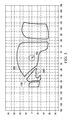
- FIGURE 3 shows a two-dimensional rectilinear field-of-view graph of the shape of windshield 200 according to one example embodiment.
- the origin of the graph of FIGURE 3 is based on design eye point 300.
- a design eye point may represent a design reference point representative of a designed location of a pilot's eye.
- Each aircraft may have one or more design eye points.
- a design eye pilot may exist for each pilot, and each pilot may have more than one design eye point (e.g., a design range or area).
- Aircraft components such as the windshields and instrumentation panel, may be designed at least in part relative to this design eye point.
- the design eye point may represent the optimum location for visibility, inside and/or outside the cockpit, as well as the optimum position for access to the aircraft instruments.
- Some aircraft manufacturers may provide reference markers for pilots to use while making seat adjustments; the intent of these reference markers may be to have the pilot adjust the seat in order for the eyes of the pilot to be at or near the design eye point.
- FIGURE 3 refers to a design eye point, teachings of certain embodiments recognize that other reference points may be used.
- FIGURE 3 refers to a single design eye point 300, design eye point 300 may be representative of multiple design eye points (e.g., a design range or area).
- windshields 200 and 200' are viewed from the right pilot seat inside rotorcraft 100.
- FIGURE 3 shows a two-dimensional representation, the three-dimensional location of design eye point 300 would be a distance away from windshield 200 inside the aircraft because that is where the pilot is located (at least, according to design).
- Coordinates in FIGURE 3 may be identified by reference to the location of design eye point 300 within rotorcraft 100.
- coordinates to the left of design eye point 300 are those coordinates left of the pilot from the pilot's perspective (and to the left of design eye point 300 in FIGURE 3 ).
- coordinates to the right of design eye point 300 are those coordinates right of the pilot from the pilot's perspective (and to the right of design eye point 300 in FIGURE 3 ).
- windshield 200' may be a mirror-image of windshield 200.
- coordinates to the right of design eye point 300 of windshield 200 may be to the left of design eye point 300' of windshield 200'.
- windshield 200 includes coordinates at a first point located twenty degrees above and forty degrees to the (right) side of design eye point 300 and a second point located thirty degrees below and forty degrees to the same side of design eye point 300 as the first point (the right side).
- windshield 200 includes translucent material (e.g., glass) extending continuously between the first and second points.
- the example windshield 200 of FIGURE 3 may include translucent material that continuously extends from the first and second points to additional coordinates.
- the translucent material extends continuously to a point located twenty degrees above and forty degrees to the side of the design reference point opposite the first and second points (the left side in FIGURE 3 ).
- the translucent material extends continuously to a point located forty degrees above and forty degrees to the same side of the design reference point as the first and second points (the right side in FIGURE 3 ).
- the translucent material extends continuously to a point located fifty degrees below and fifty degrees to the same side of the design reference point as the first and second points (the right side in FIGURE 3 ).
- the translucent material extends continuously to a point located thirty-five degrees above and forty degrees to the side of the design reference point opposite the first and second points (the left side in FIGURE 3 ). As yet another example, in some embodiments, the translucent material extends continuously to a point located ten degrees below and twenty degrees to the side of the design reference point opposite the first and second points (the left side in FIGURE 3 ).
- windshield 200 may include different coordinates, teachings of certain embodiments recognize that windshield 200 may be of a limited size while still providing visibility of both the area in front of the rotorcraft and the ground proximate to the rotorcraft when the rotorcraft is operating near the ground.
- windshield 200 is not a glass canopy that fully surrounds the cockpit (such as found on the Bell 47). Rather, windshield 200 is bounded by and fixably coupled to the frame of body 130.
- windshield 200 does not include translucent material that continuously extends to a point located twenty degrees above and seventy degrees to the side of the design reference point opposite the first and second points (the left side of FIGURE 3 ). Rather, this coordinate is occupied by the center post 135 that separates windshield 200 from windshield 200'.
- windshields 200 and 200' are coupled to body 130. Coupling windshields 200 and 200' to body 130, however, may subject windshields 200 and 200' to a risk of cracking. For example, in some embodiments, windshields 200 and 200' have a higher coefficient of thermal expansion than body 130. In this example, temperature changes may cause windshield 200 and/or 200' to crack. In another example, windshields 200 and 200' may be subject to external loads (e.g., from a birdstrike), and windshields 200 and 200' crack when transferring forces to body 130. Accordingly, teachings of certain embodiments recognize the capability to couple windshields 200 and 200' to body 130 while protecting against thermal expansion and isolating external loads from body 130.
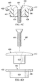
- FIGURES 4A-4D show an attachment device 400 according to one example embodiment.
- FIGURE 4A shows an assembled side view of attachment device 400
- FIGURE 4B shows an assembled top view of attachment device 400
- FIGURE 4C shows a cross-section side view of attachment device 400
- FIGURE 4D shows a disassembled side view of attachment device 400.
- windshields 200 and 200' may be attached to body 130 using attachment devices 400.
- attachment device 400 features three primary components: a fastener portion 410, an elastomeric load isolator 420, and a bolt 430.
- Fastener portion 410 has an opening therethrough that is configured to receive bolt 430.
- Fastener portion 410 may be made from any suitable material, including both metallic and non-metallic materials.
- fastener portion 410 is plastic, such as a thermoplastic or thermoset.
- fastener portion 410 is carbon fiber.
- fastener portion 410 is formed from an injection-molding process. For example, fastener portion 410 may injection-molded using a nylon 6-6 composition with 40% fiberglass.
- fastener portion 410 may include a head portion 412 and a body portion 414.
- head portion 412 may be configured to retain windshield 200 against body 130, and body portion 414 may be configured to reside within an opening in windshield 200.
- Elastomeric load isolator 420 surrounds fastener portion 410 and separates fastener portion 410 from windshield 200.
- Elastomeric load isolator 420 may help manage forces that may be transmitted between body 130 and windshield 200.
- elastomeric load isolator 420 may help distribute shear stresses over a larger and softer area.
- elastomeric load isolator 420 may help prevent windshield 200 from being subject to vibrations of body 130 or prevent windshield 200 from exerting forces on body 130, such as forces due to birdstrikes or thermal expansion. Teachings of certain embodiments recognize that managing and/or limiting the transfer of forces between body 130 and windshield 200 may reduce failures in windshield 200.
- elastomeric load isolator 420 may include a head portion 422 and a body portion 424.
- head portion 422 may separate head portion 412 from windshield 200
- body portion 424 may separate body portion 414 from windshield 200.
- Elastomeric load isolator 420 may be made from any suitable material.
- elastomeric load isolator 420 is formed from an elastomeric material.
- An elastomeric material is a material, such as a polymer, having the property of viscoelasticity (colloquially, "elasticity").
- An example of an elastomeric material is rubber.
- Elastomeric materials generally have a low Young's modulus and a high yield strain when compared to other materials.
- Elastomeric materials are typically thermosets having long polymer chains that cross-link during curing (i.e., vulcanizing). Elastomeric materials may absorb energy during compression.
- Bolt 430 may extend through the opening of fastener portion 410 and couple fastener portion 410 to body 130. Coupling fastener portion 410 to body 130 may restrain windshield 200 against body 130 without excessive clamp-up force that could cause the windshield to crack. In some embodiments, providing bolt 430 through the opening in fastener portion 410 results in torque being exerted on fastener portion 410. For example, bolt 430 may thread into fastener portion 410. As another example, bolt 430 may exert torque on fastener portion 410 when the head of bolt 430 tightens against head portion 414.
- FIGURES 5A, 5B , and 5C show attachment devices 400 installed in openings 500 of windshield 200 according to one example embodiment.
- FIGURE 5A shows a perspective view of windshield 200
- FIGURE 5B shows a detailed perspective view of an attachment device 400 installed in an opening 500
- FIGURE 5C shows a cross-section view of the attachment device 400 of FIGURE 5B installed in opening 500.
- each opening 500 is larger than body portion 424 of elastomeric load isolator 420.
- opening 500 is sufficiently larger than attachment device 400 such that a gap exists between elastomeric load isolator 420 and the interior surface of opening 400 when attachment device 400 is positioned through opening 500.
- teachings of certain embodiments recognize that providing space between elastomeric load isolator 420 and opening 500 may help prevent damage to windshield 200. For example, providing space between elastomeric load isolator 420 and opening 500 may allow windshield 200 to flex and shift in response to thermal expansion and external forces (e.g., birdstrikes).
- providing space between elastomeric load isolator 420 and opening 500 may allow windshield 200 to flex and shift in response to thermal expansion and external forces (e.g., birdstrikes).
- windshield 200 may be fixably coupled to body 130 without necessarily being rigidly coupled to body 130. Rather, attachment devices 400 prevent windshield 200 from being removed from body 130, but windshield 200 may still be free to shift and flex in response to outside forces.
- head portion 522 of elastomeric load isolator 420 is in physical contact with both windshield 200 and head portion 412 of fastener portion 410.
- head portion 522 of elastomeric load isolator 420 may provide a seal preventing debris and/or moisture from passing through opening 500.
- head portion 522 includes material that seals against windshield 200 and head portion 412 of fastener portion 410.
Landscapes
- Engineering & Computer Science (AREA)
- Mechanical Engineering (AREA)
- Aviation & Aerospace Engineering (AREA)
- Securing Of Glass Panes Or The Like (AREA)
- Glass Compositions (AREA)
Abstract
According to one embodiment, a rotorcraft front windshield (200, 200')comprises a translucent material extending continuously between a point located twenty degrees above and forty degrees to the side of a design reference point and a point located thirty degrees below and forty degrees to the same side of the design reference point as the first point.
Description
- Pursuant to 35 U.S.C. § 119 (e), this application claims priority to United States Provisional Patent Application Serial No.
61/633,410 61/633,410 - This invention relates generally to aircraft windshields, and more particularly, to a rotorcraft front windshield.
- A rotorcraft may include one or more rotor systems. One example of a rotorcraft rotor system is a main rotor system. A main rotor system may generate aerodynamic lift to support the weight of the rotorcraft in flight and thrust to counteract aerodynamic drag and move the rotorcraft in forward flight. Another example of a rotorcraft rotor system is a tail rotor system. A tail rotor system may generate thrust in the same direction as the main rotor system's rotation to counter the torque effect created by the main rotor system.
- A rotorcraft may include a variety of windows. Some of these windows may allow the pilot to see outside the rotorcraft. Two examples of a rotorcraft window may include a front windshield and a chin window. A chin window may allow a pilot to see a portion of the ground proximate to the rotorcraft when the rotorcraft is operating near the ground.
- Particular embodiments of the present disclosure may provide one or more technical advantages. A technical advantage of one embodiment may include the capability to eliminate the chin window from a conventional rotorcraft. A technical advantage of one embodiment may include the capability to improve pilot visibility. A technical advantage of one embodiment may include the capability to improve safety in the event of a crash. A technical advantage of one embodiment may include the capability to protect against birdstrikes.
- Certain embodiments of the present disclosure may include some, all, or none of the above advantages. One or more other technical advantages may be readily apparent to those skilled in the art from the figures, descriptions, and claims included herein.
- To provide a more complete understanding of the present invention and the features and advantages thereof, reference is made to the following description taken in conjunction with the accompanying drawings, in which:
-
FIGURE 1 shows a rotorcraft according to one example embodiment; -
FIGURE 2A shows a perspective view of the nose portion of the rotorcraft ofFIGURE 1 according to one example embodiment; -
FIGURE 2B shows a side view of the nose portion ofFIGURE 2A ; -
FIGURE 2C shows a front view of the nose portion ofFIGURE 2A ; -
FIGURE 2D shows a top view of the nose portion ofFIGURE 2A ; -
FIGURE 3 shows a two-dimensional rectilinear field-of-view graph of the shape of the windshield ofFIGURES 2A-2D according to one example embodiment; -
FIGURE 4A shows an assembled side view of an attachment device for attaching the windshield ofFIGURE 3 to the rotorcraft ofFIGURE 1 according to one example embodiment; -
FIGURE 4B shows an assembled top view of theattachment device 400 ofFIGURE 4A ; -
FIGURE 4C shows a cross-section side view of theattachment device 400 ofFIGURE 4A ; -
FIGURE 4D shows a disassembled side view of theattachment device 400 ofFIGURE 4A ; -
FIGURES 5A, 5B , and5C show attachment devices 400 installed inopenings 500 ofwindshield 200 according to one example embodiment.FIGURE 5A shows a perspective view ofwindshield 200,FIGURE 5B shows a detailed perspective view of anattachment device 400 installed in anopening 500, andFIGURE 5C shows a cross-section view of theattachment device 400 ofFIGURE 5B installed in opening 500. -
FIGURE 1 shows arotorcraft 100 according to one example embodiment. Rotorcraft 100 features arotor system 110,blades 120, afuselage 130, alanding gear 140, and anempennage 150.Rotor system 110 may rotateblades 120.Rotor system 110 may include a control system for selectively controlling the pitch of eachblade 120 in order to selectively control direction, thrust, and lift ofrotorcraft 100.Fuselage 130 represents the body ofrotorcraft 100 and may be coupled torotor system 110 such thatrotor system 110 andblades 120 may movefuselage 130 through the air.Landing gear 140 supportsrotorcraft 100 when rotorcraft 100 is landing and/or when rotorcraft 100 is at rest on the ground.Empennage 150 represents the tail section of the aircraft and features components of arotor system 110 and blades 120'. Blades 120' may provide thrust in the same direction as the rotation ofblades 120 so as to counter the torque effect created byrotor system 110 andblades 120. Teachings of certain embodiments relating to rotor systems described herein may apply torotor system 110 and/or other rotor systems, such as other tilt rotor and helicopter rotor systems. It should also be appreciated that teachings fromrotorcraft 100 may apply to aircraft other than rotorcraft, such as airplanes and unmanned aircraft, to name a few examples. - The pilot of a rotorcraft may be asked to perform a variety of maneuvers near the ground or other obstacles. Examples of such maneuvers may include take-off and landing. In these examples, it may be important for the pilot to have visibility of both the area in front of the rotorcraft and the ground proximate to the rotorcraft when the rotorcraft is operating near the ground.
- Typically, a rotorcraft is configured with two windows to provide these views: a front windshield providing visibility in front of the rotorcraft, and a separate chin window providing visibility of the ground proximate to the rotorcraft when the rotorcraft is operating on the ground. This separate chin window is typically provided near the legs/feet of the pilot in order to provide a viewing angle of the ground proximate to the rotorcraft when the rotorcraft is operating on the ground.
- This separate chin window, however, may raise a number of issues. First, the pilot may not have a clear line-of-sight to look through the chin window. For example, the foot pedals, instrument panel, and pilot's legs and feet may all block the pilot's ability to look through the chin window. In addition, the chin window may raise safety concerns in the event of a crash because of its location. In particular, the chin window may break when the rotorcraft "ditches" in bodies of water and cause shattered glass and water to enter the cockpit at a dangerously high velocity. Furthermore, the chin window may take valuable space within the aircraft since nothing can blow its view if it is to maintain its functionality. The limited space where the chin window is located is very valuable and may be better suited for other equipment, such as floatation kits. Accordingly, teachings of certain embodiments recognize the capability to eliminate the chin window from a rotorcraft. In particular, teachings of certain embodiments recognize the capability to provide a front windshield that provides visibility of both the area in front of the rotorcraft and the ground proximate to the rotorcraft when the rotorcraft is operating near the ground.
- For example, the
rotorcraft 100 ofFIGURE 1 shows a front windshield that provides visibility of both the area in front of the rotorcraft and the ground proximate to the rotorcraft when the rotorcraft is operating near the ground.FIGURES 2A-2D show detailed views of the nose portion of therotorcraft 100 ofFIGURE 1. FIGURE 2A shows a perspective view,FIGURE 2B shows a side view,FIGURE 2C shows a front view, andFIGURE 2D shows a top view. - As seen in
FIGURES 2A-2D ,rotorcraft 100 features twofront windshields 200 and 200'. Eachfront windshield 200/200' wraps from the front ofbody 130 around to the side ofbody 130. In this example, the front-facing portion of each front windshield provides visibility of the area in front of the rotorcraft, and the side-facing portion of each front windshield provides visibility of the ground proximate to the rotorcraft when the rotorcraft is operating near the ground. - In addition, eliminating any post between the front-facing and side-facing portions of
front windshields 200 and 200' may increase flexibility offront windshields 200 and 200' and improve the ability offront windshields 200 and 200' to withstand birdstrikes. For example,front windshields 200/200' may receive impact of a birdstrike and then allow this energy to propagate without shattering the windshield due to large shear stresses that develop where the windshield attaches to structure or posts. -
FIGURE 3 shows a two-dimensional rectilinear field-of-view graph of the shape ofwindshield 200 according to one example embodiment. The origin of the graph ofFIGURE 3 is based on design eye point 300. A design eye point may represent a design reference point representative of a designed location of a pilot's eye. Each aircraft may have one or more design eye points. For example, a design eye pilot may exist for each pilot, and each pilot may have more than one design eye point (e.g., a design range or area). - Aircraft components, such as the windshields and instrumentation panel, may be designed at least in part relative to this design eye point. For example, in some embodiments, the design eye point may represent the optimum location for visibility, inside and/or outside the cockpit, as well as the optimum position for access to the aircraft instruments. Some aircraft manufacturers may provide reference markers for pilots to use while making seat adjustments; the intent of these reference markers may be to have the pilot adjust the seat in order for the eyes of the pilot to be at or near the design eye point. Although the example of
FIGURE 3 refers to a design eye point, teachings of certain embodiments recognize that other reference points may be used. In addition, althoughFIGURE 3 refers to a single design eye point 300, design eye point 300 may be representative of multiple design eye points (e.g., a design range or area). - In the example of
FIGURE 3 ,windshields 200 and 200' are viewed from the right pilot seat insiderotorcraft 100. AlthoughFIGURE 3 shows a two-dimensional representation, the three-dimensional location of design eye point 300 would be a distance away fromwindshield 200 inside the aircraft because that is where the pilot is located (at least, according to design). - Coordinates in
FIGURE 3 may be identified by reference to the location of design eye point 300 withinrotorcraft 100. Thus, for example, coordinates to the left of design eye point 300 are those coordinates left of the pilot from the pilot's perspective (and to the left of design eye point 300 inFIGURE 3 ). In addition, coordinates to the right of design eye point 300 are those coordinates right of the pilot from the pilot's perspective (and to the right of design eye point 300 inFIGURE 3 ). Furthermore, windshield 200' may be a mirror-image ofwindshield 200. Thus, coordinates to the right of design eye point 300 ofwindshield 200 may be to the left of design eye point 300' of windshield 200'. - In the example of
FIGURE 3 ,windshield 200 includes coordinates at a first point located twenty degrees above and forty degrees to the (right) side of design eye point 300 and a second point located thirty degrees below and forty degrees to the same side of design eye point 300 as the first point (the right side). As seen inFIGURE 3 ,windshield 200 includes translucent material (e.g., glass) extending continuously between the first and second points. - Furthermore, the
example windshield 200 ofFIGURE 3 may include translucent material that continuously extends from the first and second points to additional coordinates. For example, in some embodiments, the translucent material extends continuously to a point located twenty degrees above and forty degrees to the side of the design reference point opposite the first and second points (the left side inFIGURE 3 ). As another example, in some embodiments, the translucent material extends continuously to a point located forty degrees above and forty degrees to the same side of the design reference point as the first and second points (the right side inFIGURE 3 ). As yet another example, in some embodiments, the translucent material extends continuously to a point located fifty degrees below and fifty degrees to the same side of the design reference point as the first and second points (the right side inFIGURE 3 ). As yet another example, in some embodiments, the translucent material extends continuously to a point located thirty-five degrees above and forty degrees to the side of the design reference point opposite the first and second points (the left side inFIGURE 3 ). As yet another example, in some embodiments, the translucent material extends continuously to a point located ten degrees below and twenty degrees to the side of the design reference point opposite the first and second points (the left side inFIGURE 3 ). - Although different embodiments of
windshield 200 may include different coordinates, teachings of certain embodiments recognize thatwindshield 200 may be of a limited size while still providing visibility of both the area in front of the rotorcraft and the ground proximate to the rotorcraft when the rotorcraft is operating near the ground. For example,windshield 200 is not a glass canopy that fully surrounds the cockpit (such as found on the Bell 47). Rather,windshield 200 is bounded by and fixably coupled to the frame ofbody 130. - Thus, in the example of
FIGURE 3 , a variety of coordinates may fall outside the boundaries ofwindshield 200. For example, as seen inFIGURE 3 ,windshield 200 does not include translucent material that continuously extends to a point located twenty degrees above and seventy degrees to the side of the design reference point opposite the first and second points (the left side ofFIGURE 3 ). Rather, this coordinate is occupied by thecenter post 135 that separateswindshield 200 from windshield 200'. - As explained above,
windshields 200 and 200' are coupled tobody 130. Couplingwindshields 200 and 200' tobody 130, however, may subjectwindshields 200 and 200' to a risk of cracking. For example, in some embodiments,windshields 200 and 200' have a higher coefficient of thermal expansion thanbody 130. In this example, temperature changes may causewindshield 200 and/or 200' to crack. In another example,windshields 200 and 200' may be subject to external loads (e.g., from a birdstrike), andwindshields 200 and 200' crack when transferring forces tobody 130. Accordingly, teachings of certain embodiments recognize the capability to couplewindshields 200 and 200' tobody 130 while protecting against thermal expansion and isolating external loads frombody 130. -
FIGURES 4A-4D show anattachment device 400 according to one example embodiment.FIGURE 4A shows an assembled side view ofattachment device 400,FIGURE 4B shows an assembled top view ofattachment device 400,FIGURE 4C shows a cross-section side view ofattachment device 400, andFIGURE 4D shows a disassembled side view ofattachment device 400. In operation, as will be explained in greater detail below,windshields 200 and 200' may be attached tobody 130 usingattachment devices 400. - As seen in
FIGURES 4A-4D ,attachment device 400 features three primary components: afastener portion 410, anelastomeric load isolator 420, and abolt 430.Fastener portion 410 has an opening therethrough that is configured to receivebolt 430.Fastener portion 410 may be made from any suitable material, including both metallic and non-metallic materials. In some embodiments,fastener portion 410 is plastic, such as a thermoplastic or thermoset. In one example embodiment,fastener portion 410 is carbon fiber. In some embodiments,fastener portion 410 is formed from an injection-molding process. For example,fastener portion 410 may injection-molded using a nylon 6-6 composition with 40% fiberglass. - As seen in the example of
FIGURE 4C ,fastener portion 410 may include ahead portion 412 and abody portion 414. In some embodiments,head portion 412 may be configured to retainwindshield 200 againstbody 130, andbody portion 414 may be configured to reside within an opening inwindshield 200. -
Elastomeric load isolator 420 surroundsfastener portion 410 and separatesfastener portion 410 fromwindshield 200.Elastomeric load isolator 420 may help manage forces that may be transmitted betweenbody 130 andwindshield 200. For example,elastomeric load isolator 420 may help distribute shear stresses over a larger and softer area. In addition,elastomeric load isolator 420 may help preventwindshield 200 from being subject to vibrations ofbody 130 or preventwindshield 200 from exerting forces onbody 130, such as forces due to birdstrikes or thermal expansion. Teachings of certain embodiments recognize that managing and/or limiting the transfer of forces betweenbody 130 andwindshield 200 may reduce failures inwindshield 200. - As seen in the example of
FIGURE 4C ,elastomeric load isolator 420 may include ahead portion 422 and abody portion 424. In some embodiments,head portion 422 may separatehead portion 412 fromwindshield 200, andbody portion 424 may separatebody portion 414 fromwindshield 200. -
Elastomeric load isolator 420 may be made from any suitable material. In some embodiments,elastomeric load isolator 420 is formed from an elastomeric material. An elastomeric material is a material, such as a polymer, having the property of viscoelasticity (colloquially, "elasticity"). An example of an elastomeric material is rubber. Elastomeric materials generally have a low Young's modulus and a high yield strain when compared to other materials. Elastomeric materials are typically thermosets having long polymer chains that cross-link during curing (i.e., vulcanizing). Elastomeric materials may absorb energy during compression. -
Bolt 430 may extend through the opening offastener portion 410 andcouple fastener portion 410 tobody 130.Coupling fastener portion 410 tobody 130 may restrainwindshield 200 againstbody 130 without excessive clamp-up force that could cause the windshield to crack. In some embodiments, providingbolt 430 through the opening infastener portion 410 results in torque being exerted onfastener portion 410. For example, bolt 430 may thread intofastener portion 410. As another example, bolt 430 may exert torque onfastener portion 410 when the head ofbolt 430 tightens againsthead portion 414. -
FIGURES 5A, 5B , and5C show attachment devices 400 installed inopenings 500 ofwindshield 200 according to one example embodiment.FIGURE 5A shows a perspective view ofwindshield 200,FIGURE 5B shows a detailed perspective view of anattachment device 400 installed in anopening 500, andFIGURE 5C shows a cross-section view of theattachment device 400 ofFIGURE 5B installed inopening 500. In the examples ofFIGURE 5A-5C , eachopening 500 is larger thanbody portion 424 ofelastomeric load isolator 420. In these examples, opening 500 is sufficiently larger thanattachment device 400 such that a gap exists betweenelastomeric load isolator 420 and the interior surface of opening 400 whenattachment device 400 is positioned throughopening 500. Teachings of certain embodiments recognize that providing space betweenelastomeric load isolator 420 andopening 500 may help prevent damage towindshield 200. For example, providing space betweenelastomeric load isolator 420 andopening 500 may allowwindshield 200 to flex and shift in response to thermal expansion and external forces (e.g., birdstrikes). - In this manner,
windshield 200 may be fixably coupled tobody 130 without necessarily being rigidly coupled tobody 130. Rather,attachment devices 400 preventwindshield 200 from being removed frombody 130, butwindshield 200 may still be free to shift and flex in response to outside forces. - As seen in
FIGURE 5C , head portion 522 ofelastomeric load isolator 420 is in physical contact with bothwindshield 200 andhead portion 412 offastener portion 410. Teachings of certain embodiments recognize that head portion 522 ofelastomeric load isolator 420 may provide a seal preventing debris and/or moisture from passing throughopening 500. For example, as shown inFIGURE 5C , head portion 522 includes material that seals againstwindshield 200 andhead portion 412 offastener portion 410. - Modifications, additions, or omissions may be made to the systems and apparatuses described herein without departing from the scope of the invention. The components of the systems and apparatuses may be integrated or separated. Moreover, the operations of the systems and apparatuses may be performed by more, fewer, or other components. The methods may include more, fewer, or other steps. Additionally, steps may be performed in any suitable order.
- Although several embodiments have been illustrated and described in detail, it will be recognized that substitutions and alterations are possible without departing from the spirit and scope of the present invention, as defined by the appended claims.
- To aid the Patent Office, and any readers of any patent issued on this application in interpreting the claims appended hereto, applicants wish to note that they do not intend any of the appended claims to invoke paragraph 6 of 35 U.S.C. § 112 as it exists on the date of filing hereof unless the words "means for" or "step for" are explicitly used in the particular claim.
Claims (12)
- A windshield, comprising a translucent material extending continuously between:a point located twenty degrees above and forty degrees to the side of a design reference point; anda point located thirty degrees below and forty degrees to the same side of the design reference point as the first point.
- A rotorcraft, comprising:a body;a power train coupled to the body and comprising a power source and a drive shaft coupled to the power source;a hub;a rotor blade coupled to the hub; anda front windshield coupled to the body, the front windshield comprising a windshield of claim 1
- A rotorcraft, comprising:a body;a power train coupled to the body and comprising a power source and a drive shaft coupled to the power source;a hub;a rotor blade coupled to the hub; anda front windshield coupled to the body, the front windshield comprising a translucent material extending continuously and unobstructed between a first point located twenty degrees above and forty degrees to the side of a design reference point and a second point located thirty degrees below and forty degrees to the same side of the design reference point as the first point.
- The windshield of claim 1, or the rotorcraft of claim 2 or 3, wherein the design reference point is a design-eye reference point representative of a designed location of a pilot's eye.
- The windshield of claim 1 or 4, or the rotorcraft of claims 2 to 4, wherein the design reference point is located a distance away from the translucent material.
- The rotorcraft of any of claims 2 to 5, wherein the front windshield is fixably coupled to the body, or the windshield of claim 1 or claim 4 or 5, wherein the front windshield is configured to be fixably coupled to a body of a rotorcraft.
- The windshield of claim 1, or any of claims 4 to 6, or the rotorcraft of any of claims 2 to 6, wherein the translucent material does not extend continuously to a point located twenty degrees above and seventy degrees to the side of the design reference point opposite the first and second points.
- The windshield of claim 1 or of any of claims 4 to 7, or the rotorcraft of any of claims 2 to 7, wherein the translucent material extends continuously to a point located twenty degrees above and forty degrees to the side of the design reference point opposite the first and second points.
- The windshield of claim 1 or any of claims 4 to 8, or the rotorcraft of any of claims 2 to 8, wherein the translucent material extends continuously to a point located forty degrees above and forty degrees to the same side of the design reference point as the first and second points.
- The windshield of claim 1 or any of claims 4 to 9, or the rotorcraft of any of claims 2 to 9, wherein the translucent material extends continuously to a point located fifty degrees below and fifty degrees to the same side of the design reference point as the first and second points.
- The windshield of claim 1 or any of claims 4 to 10, or the rotorcraft of any of claims 2 to 10, wherein the translucent material extends continuously to a point located thirty-five degrees above and forty degrees to the side of the design reference point opposite the first and second points.
- The windshield of claim 1 or any of claims 4 to 11, or the rotorcraft of any of claims 2 to 11, wherein the translucent material extends continuously to a point located ten degrees below and twenty degrees to the side of the design reference point opposite the first and second points.
Applications Claiming Priority (2)
| Application Number | Priority Date | Filing Date | Title |
|---|---|---|---|
| US201261633410P | 2012-02-10 | 2012-02-10 | |
| US13/744,472 US20130206908A1 (en) | 2012-02-10 | 2013-01-18 | Rotorcraft Front Windshield |
Publications (1)
| Publication Number | Publication Date |
|---|---|
| EP2626293A1 true EP2626293A1 (en) | 2013-08-14 |
Family
ID=47681745
Family Applications (1)
| Application Number | Title | Priority Date | Filing Date |
|---|---|---|---|
| EP13153926.4A Withdrawn EP2626293A1 (en) | 2012-02-10 | 2013-02-04 | Rotorcraft front windshield |
Country Status (5)
| Country | Link |
|---|---|
| US (1) | US20130206908A1 (en) |
| EP (1) | EP2626293A1 (en) |
| CN (1) | CN103241361A (en) |
| BR (1) | BR102013002950A2 (en) |
| CA (1) | CA2804330A1 (en) |
Cited By (2)
| Publication number | Priority date | Publication date | Assignee | Title |
|---|---|---|---|---|
| EP3056365A1 (en) * | 2015-02-12 | 2016-08-17 | Hammerglass AB | Protective windshield arrangement |
| EP3335981A1 (en) * | 2016-12-13 | 2018-06-20 | The Boeing Company | Apparatuses and methods for aerodynamic window assemblies |
Families Citing this family (1)
| Publication number | Priority date | Publication date | Assignee | Title |
|---|---|---|---|---|
| EP3120104A4 (en) * | 2014-03-18 | 2017-11-15 | Sikorsky Aircraft Corporation | Armored window |
Citations (4)
| Publication number | Priority date | Publication date | Assignee | Title |
|---|---|---|---|---|
| GB491358A (en) * | 1936-12-28 | 1938-08-31 | Messerschmitt Boelkow Blohm | Improvements in and relating to cabins for aircraft |
| US3510087A (en) * | 1968-05-06 | 1970-05-05 | James C Strickland | Air coupling system for helicopters |
| GB2028748A (en) * | 1978-08-28 | 1980-03-12 | Agusta Aeronaut Costr | Helicopter |
| DE102009040277A1 (en) * | 2009-09-04 | 2011-03-10 | Otmar Birkner | Gyrocopter has trunk and partial transparent cover, where cover is curved in convex sections and is closed in flight direction and possesses laterally arranged opening |
Family Cites Families (35)
| Publication number | Priority date | Publication date | Assignee | Title |
|---|---|---|---|---|
| US2380289A (en) * | 1940-11-26 | 1945-07-10 | V J Burnelli Airplanes Inc | Miltary aircraft |
| US2379194A (en) * | 1942-01-09 | 1945-06-26 | Lockheed Aircraft Corp | Transparent closure mounting |
| US2372939A (en) * | 1942-07-03 | 1945-04-03 | Glenn L Martin Co | Transparent nose turret |
| US2373214A (en) * | 1943-01-11 | 1945-04-10 | Wolkenhauer Gustav | Shielding device |
| US2533548A (en) * | 1947-05-16 | 1950-12-12 | Nl Vliegtuigenfabriek Fokker N | Cockpit cover for airplanes |
| US2701899A (en) * | 1948-06-26 | 1955-02-15 | Goodrich Co B F | Inflatable sealing strip |
| US2659462A (en) * | 1948-09-17 | 1953-11-17 | Northrop Aircraft Inc | Attachment for plastic enclosures |
| US3016548A (en) * | 1958-09-15 | 1962-01-16 | Nelson A Taylor Co Inc | Two part glass windshield to rest on a crowned boat deck |
| US3093844A (en) * | 1961-03-28 | 1963-06-18 | Standard Products Co | Windshield assembly |
| US3093846A (en) * | 1961-03-28 | 1963-06-18 | Standard Products Co | Windshield operating mechanism |
| US3259345A (en) * | 1963-10-11 | 1966-07-05 | North American Aviation Inc | Enclosure method and means |
| US3547382A (en) * | 1968-05-14 | 1970-12-15 | Stanley Aviation Corp | Apparatus for removing a crew compartment enclosure structure from an air or space vehicle |
| SE329091B (en) * | 1969-07-07 | 1970-09-28 | Saab Ab | |
| US3757725A (en) * | 1971-09-24 | 1973-09-11 | Us Navy | Right spherical segment-glass shell-to metal-joint |
| US3866242A (en) * | 1972-10-27 | 1975-02-18 | Goodyear Aerospace Corp | Protective shield |
| US3894305A (en) * | 1973-05-11 | 1975-07-15 | American Marine Ind | Boat windshield |
| US4579301A (en) * | 1984-03-07 | 1986-04-01 | Rolf Brand | Pilot module |
| USD289994S (en) * | 1984-05-29 | 1987-05-26 | Mcnab Robert B | Helicopter window |
| DE3826636A1 (en) * | 1988-08-05 | 1990-02-08 | Messerschmitt Boelkow Blohm | COCKPIT, ESPECIALLY FOR A HELICOPTER |
| US5875997A (en) * | 1997-03-18 | 1999-03-02 | Al-Sabah; Sabah Naser | Aircraft having raised and rearward positioned cockpit |
| USD425853S (en) * | 1998-04-17 | 2000-05-30 | Finmeccanica S.P.A. | Helicopter |
| US6647915B1 (en) * | 2002-06-20 | 2003-11-18 | Malibu Boats West, Inc. | Windshield edge assembly and method |
| US6848655B2 (en) * | 2003-02-13 | 2005-02-01 | The Boeing Company | Frameless aircraft canopy actuation system and method |
| US7143979B2 (en) * | 2003-05-30 | 2006-12-05 | The Boeing Company | Vehicle windshield |
| US7134705B2 (en) * | 2003-09-17 | 2006-11-14 | Larson Bruce E | Windshield for a motorcycle, motor tricycle or bicycle |
| US7281485B1 (en) * | 2005-06-16 | 2007-10-16 | Bach Darren A | Windshield trim assembly and method |
| US7997529B2 (en) * | 2006-01-19 | 2011-08-16 | The Boeing Company | Compliant panel for aircraft |
| US20080099614A1 (en) * | 2006-10-16 | 2008-05-01 | Blue Linden S | Unitary one-piece windshield |
| US7434534B2 (en) * | 2007-02-12 | 2008-10-14 | Taylor Made Group, Inc. | Fastener for a boat cover |
| US7441510B1 (en) * | 2007-04-03 | 2008-10-28 | Darren Ashley Bach | Marine windshield frame and method of manufacture |
| US20080271857A1 (en) * | 2007-05-04 | 2008-11-06 | Linda Kay Swadling | Foldable shades for aircraft cockpits |
| US7845304B2 (en) * | 2007-10-09 | 2010-12-07 | Taylor Made Group, Llc | Removable boat windshield |
| USD678171S1 (en) * | 2012-02-10 | 2013-03-19 | Bell Helicopter Textron Inc. | Helicopter nose design |
| USD678172S1 (en) * | 2012-02-10 | 2013-03-19 | Bell Helicopter Textron Inc. | Helicopter front windshields |
| US9038952B2 (en) * | 2012-02-10 | 2015-05-26 | Bell Helicopter Textron Inc. | Attachment devices for rotorcraft front windshield |
-
2013
- 2013-01-18 US US13/744,472 patent/US20130206908A1/en not_active Abandoned
- 2013-02-01 CA CA2804330A patent/CA2804330A1/en not_active Abandoned
- 2013-02-04 EP EP13153926.4A patent/EP2626293A1/en not_active Withdrawn
- 2013-02-06 BR BRBR102013002950-5A patent/BR102013002950A2/en not_active Application Discontinuation
- 2013-02-16 CN CN2013100513737A patent/CN103241361A/en active Pending
Patent Citations (4)
| Publication number | Priority date | Publication date | Assignee | Title |
|---|---|---|---|---|
| GB491358A (en) * | 1936-12-28 | 1938-08-31 | Messerschmitt Boelkow Blohm | Improvements in and relating to cabins for aircraft |
| US3510087A (en) * | 1968-05-06 | 1970-05-05 | James C Strickland | Air coupling system for helicopters |
| GB2028748A (en) * | 1978-08-28 | 1980-03-12 | Agusta Aeronaut Costr | Helicopter |
| DE102009040277A1 (en) * | 2009-09-04 | 2011-03-10 | Otmar Birkner | Gyrocopter has trunk and partial transparent cover, where cover is curved in convex sections and is closed in flight direction and possesses laterally arranged opening |
Non-Patent Citations (1)
| Title |
|---|
| "Elisport CH-7 Kompress, Radom Air Show 2007.jpg", 1 September 2007 (2007-09-01), Retrieved from the Internet <URL:http://en.wikipedia.org/wiki/File:Elisport_CH-7_Kompress,_Radom_Air_Show_2007.jpg> [retrieved on 20131001] * |

Cited By (10)
| Publication number | Priority date | Publication date | Assignee | Title |
|---|---|---|---|---|
| EP3056365A1 (en) * | 2015-02-12 | 2016-08-17 | Hammerglass AB | Protective windshield arrangement |
| WO2016128328A1 (en) * | 2015-02-12 | 2016-08-18 | Hammerglass Ab | Protective windshield arrangement |
| CN107249913A (en) * | 2015-02-12 | 2017-10-13 | 哈默玻璃制品公司 | Protectiveness windshield device |
| KR20170126922A (en) * | 2015-02-12 | 2017-11-20 | 해머글라스 에이비 | Protective windshield arrangement |
| AU2016218084B2 (en) * | 2015-02-12 | 2019-05-16 | Hammerglass Ab | Protective windshield arrangement |
| US10293663B2 (en) | 2015-02-12 | 2019-05-21 | Hammerglass Ab | Protective windshield arrangement |
| CN107249913B (en) * | 2015-02-12 | 2019-11-08 | 哈默玻璃制品公司 | protective windshield |
| EP3335981A1 (en) * | 2016-12-13 | 2018-06-20 | The Boeing Company | Apparatuses and methods for aerodynamic window assemblies |
| US10293915B2 (en) | 2016-12-13 | 2019-05-21 | The Boeing Company | Apparatuses and methods for aerodynamic window assemblies |
| RU2760338C2 (en) * | 2016-12-13 | 2021-11-24 | Зе Боинг Компани | Aerodynamic element and method for forming the surface of aerodynamic element |
Also Published As
| Publication number | Publication date |
|---|---|
| CN103241361A (en) | 2013-08-14 |
| US20130206908A1 (en) | 2013-08-15 |
| CA2804330A1 (en) | 2013-08-10 |
| BR102013002950A2 (en) | 2015-07-14 |
Similar Documents
| Publication | Publication Date | Title |
|---|---|---|
| US10040534B2 (en) | Fuselage to wing attachment | |
| EP3677501A1 (en) | Deformable aircraft window | |
| PL2148814T3 (en) | Long range fast hybrid helicopter with longitudinal attitude control | |
| US9957802B2 (en) | Morphing trailing edge device for an airfoil | |
| US10336445B2 (en) | High flapping yoke hub assembly using a cylindrical elastomeric attachment to avoid holes | |
| EP2910464B1 (en) | Strapped windshield assembly for rotorcraft | |
| US10023294B2 (en) | Tail spar spring | |
| US20130206908A1 (en) | Rotorcraft Front Windshield | |
| US20150122953A1 (en) | Drive Link for Tiltrotor Rotor System | |
| US9604713B2 (en) | Door migration prevention system | |
| KR20140079174A (en) | Blade pitch control device for Airplane propeller | |
| US9038952B2 (en) | Attachment devices for rotorcraft front windshield | |
| EP2687441B1 (en) | Elastomeric bearing housing and mating grip for helicopter rotor system | |
| US8523104B2 (en) | Method and a rotary wing aircraft that are optimized so as to minimize the consequences for the occupants of said aircraft of an off-specification emergency landing | |
| US20240140586A1 (en) | Energy attenuating aircraft windshield corner supports, systems and methods | |
| EP3072814B1 (en) | Rotorcraft tail rotor blade assembly and method of forming the same | |
| US20170088247A1 (en) | Armored window | |
| US10023289B2 (en) | Variable-thickness windshield | |
| RU2555086C1 (en) | High-speed combined helicopter |
Legal Events
| Date | Code | Title | Description |
|---|---|---|---|
| PUAI | Public reference made under article 153(3) epc to a published international application that has entered the european phase |
Free format text: ORIGINAL CODE: 0009012 |
|
| 17P | Request for examination filed |
Effective date: 20130204 |
|
| AK | Designated contracting states |
Kind code of ref document: A1 Designated state(s): AL AT BE BG CH CY CZ DE DK EE ES FI FR GB GR HR HU IE IS IT LI LT LU LV MC MK MT NL NO PL PT RO RS SE SI SK SM TR |
|
| AX | Request for extension of the european patent |
Extension state: BA ME |
|
| 17Q | First examination report despatched |
Effective date: 20131009 |
|
| STAA | Information on the status of an ep patent application or granted ep patent |
Free format text: STATUS: THE APPLICATION HAS BEEN WITHDRAWN |
|
| 18W | Application withdrawn |
Effective date: 20140703 |