EP2625992A1 - Device for use in a blender - Google Patents
Device for use in a blender Download PDFInfo
- Publication number
- EP2625992A1 EP2625992A1 EP12154594.1A EP12154594A EP2625992A1 EP 2625992 A1 EP2625992 A1 EP 2625992A1 EP 12154594 A EP12154594 A EP 12154594A EP 2625992 A1 EP2625992 A1 EP 2625992A1
- Authority
- EP
- European Patent Office
- Prior art keywords
- tool
- cage
- tool cage
- longitudinal axis
- shape
- Prior art date
- Legal status (The legal status is an assumption and is not a legal conclusion. Google has not performed a legal analysis and makes no representation as to the accuracy of the status listed.)
- Granted
Links
Images


Classifications
-
- A—HUMAN NECESSITIES
- A47—FURNITURE; DOMESTIC ARTICLES OR APPLIANCES; COFFEE MILLS; SPICE MILLS; SUCTION CLEANERS IN GENERAL
- A47J—KITCHEN EQUIPMENT; COFFEE MILLS; SPICE MILLS; APPARATUS FOR MAKING BEVERAGES
- A47J43/00—Implements for preparing or holding food, not provided for in other groups of this subclass
- A47J43/04—Machines for domestic use not covered elsewhere, e.g. for grinding, mixing, stirring, kneading, emulsifying, whipping or beating foodstuffs, e.g. power-driven
- A47J43/044—Machines for domestic use not covered elsewhere, e.g. for grinding, mixing, stirring, kneading, emulsifying, whipping or beating foodstuffs, e.g. power-driven with tools driven from the top side
-
- A—HUMAN NECESSITIES
- A47—FURNITURE; DOMESTIC ARTICLES OR APPLIANCES; COFFEE MILLS; SPICE MILLS; SUCTION CLEANERS IN GENERAL
- A47J—KITCHEN EQUIPMENT; COFFEE MILLS; SPICE MILLS; APPARATUS FOR MAKING BEVERAGES
- A47J43/00—Implements for preparing or holding food, not provided for in other groups of this subclass
- A47J43/04—Machines for domestic use not covered elsewhere, e.g. for grinding, mixing, stirring, kneading, emulsifying, whipping or beating foodstuffs, e.g. power-driven
- A47J43/07—Parts or details, e.g. mixing tools, whipping tools
- A47J43/0705—Parts or details, e.g. mixing tools, whipping tools for machines with tools driven from the upper side
- A47J43/0711—Parts or details, e.g. mixing tools, whipping tools for machines with tools driven from the upper side mixing, whipping or cutting tools
-
- A—HUMAN NECESSITIES
- A47—FURNITURE; DOMESTIC ARTICLES OR APPLIANCES; COFFEE MILLS; SPICE MILLS; SUCTION CLEANERS IN GENERAL
- A47J—KITCHEN EQUIPMENT; COFFEE MILLS; SPICE MILLS; APPARATUS FOR MAKING BEVERAGES
- A47J43/00—Implements for preparing or holding food, not provided for in other groups of this subclass
- A47J43/04—Machines for domestic use not covered elsewhere, e.g. for grinding, mixing, stirring, kneading, emulsifying, whipping or beating foodstuffs, e.g. power-driven
- A47J43/044—Machines for domestic use not covered elsewhere, e.g. for grinding, mixing, stirring, kneading, emulsifying, whipping or beating foodstuffs, e.g. power-driven with tools driven from the top side
- A47J2043/04409—Apparatus of hand held type
- A47J2043/04427—Apparatus of hand held type with housing extending vertically in line with the tool axis
Definitions
- the present invention relates to a device for use in a blender, comprising a rotatably arranged tool for moving through food to be processed by means of the blender, and a tool cage for partially covering the tool, wherein the tool cage is shaped like a hollow cylinder having a longitudinal axis and an inner surface which exclusively comprises areas with a non-convex general shape, wherein a cross-sectional shape of the tool cage, i.e. a shape of an imaginary section perpendicular to the longitudinal axis, deviates from a circular shape and has at least one protruding area which is outside of an imaginary circle being positioned inside the tool cage and touching the inner surface while having a minimum radius.
- a cross-sectional shape of the tool cage i.e. a shape of an imaginary section perpendicular to the longitudinal axis
- the present invention also relates to a blender, comprising a device as mentioned, and means for driving the tool which is part of the device.
- a blender is a household appliance which is adapted to be used for processing food, particularly mixing, comminuting, and/or aerating food.
- the blender comprises one or more rotatably arranged tools such as whisks or knives for moving through the food.
- a rotatably arranged knife is applied, which usually has two diametrically arranged blades in a more or less flat appearance, like a propeller.
- a stick blender has a housing for accommodating components of the blender, including means such as a motor for driving the knife, and an elongated, stick-shaped device carrying the knife at an end thereof.
- the housing is shaped such that it is possible for a user to take hold of the blender in a very convenient manner, and to have a firm grip on the blender during food processing actions.
- the user inserts the stick-shaped device in a quantity of food, with the knife down, wherein the food is processed as the knife rotates.
- the user may move the blender during a food processing action, so as to continually change the location of the rotating knife in the food.
- a suitable cover which is referred to as tool cage, and which has an opening for allowing the knife to reach the food, but which prevents a user from freely touching the knife.
- tool cage a suitable cover which has an opening for allowing the knife to reach the food, but which prevents a user from freely touching the knife.
- a standard orientation of a stick blender is a vertical orientation with the knife at a downside, and in such an orientation, the tool cage is at a downside of the blender as well, and serves for preventing a user from touching the knife from the side.
- the tool cage is shaped like a tapered, hollow cylinder having an open end, like a cup, a bell, a bowl, a tulip, an umbrella, or the like.
- the tool cage may be removably arranged for cleaning purposes, for example.
- a tool cage as mentioned, suitable for use in a hand-held blender or mixer, is known from WO 99/48411 . It is noted that in this text, the words “blender” and “mixer” are regarded as equivalents, and that only the word “blender” is used.
- An inner surface of the tool cage defines a space which is accessible from below via an opening through which food is supplied and discharged during a food processing action.
- the inner surface has on its circumference individual outwardly extending wall sections for the formation of clearance spaces, wherein the wall sections serve primarily for the diversion, comminution, and/or enhanced mixing of food, while the clearance spaces are used for receiving and discharging the food.
- a cross-section of the tool cage is shaped like an undulating ring, with alternating concave and convex portions.
- another tool cage which includes an inner surface having a cross-section which takes the form of a substantially regular polygon with at least five and preferably fifteen sides.
- food materials are comminuted in the tool cage particularly rapidly. After the food impinges against the inner surface, the polygonal profile causes the food to be deflected from the inner surface and to be directed back to the area where the knife is for further comminution.
- a device with a tool cage having an inner surface which exclusively comprises areas with a non-convex general shape is provided.
- the inner surface of the tool cage only has portions with a straight and/or concave general shape, on the basis of which a good cleanability of the inner surface is obtained.
- a flow of food inside the tool cage can take place in a smooth and unhindered manner, due to the absence of convex portions of the inner surface in general.
- the tool cage is shaped like a hollow cylinder.
- the term cylinder is not limited to the most common concept of this term, which involves a straight longitudinal axis and a circular circumference about the longitudinal axis.
- a cross-sectional shape of the tool cage deviates from a circular shape in that this shape has at least one protruding area which is outside of an imaginary circle being centrally positioned about the longitudinal axis and touching the inner surface while having a minimum radius.
- the protruding area has an important function in allowing transport of food in and out of the tool cage, among other things.
- a dimensionless characteristic value is introduced, and a range is determined for this value, so that it is possible to predict the effectiveness of certain designs, namely by determining if the characteristic values of the designs are inside or outside of the range.
- the dimensionless characteristic value can be regarded as a performance indication number.
- the present invention proposes to use a dimensionless characteristic value which defines the geometry of a tool cage on the basis of a relation between a cross-sectional area which is used for blending, i.e. a cross-sectional area which is covered by the rotatably arranged tool, and a cross-sectional area of a protruding area, at the highest level of the tool, i.e. the level which is both reached by the tool inside the tool cage and the furthest remote from an open end of the tool cage, for the total number of protruding areas.
- the cross-sectional shape of the tool cage can have a rotational symmetry about the longitudinal axis, wherein the number of protruding areas can be easily determined, and may be the same as the number associated with the rotational symmetry.
- the maximum radius of the tool is found on the basis of a largest radial dimension of the tool, i.e. a largest distance between a tip of the tool and an axis about which the tool is rotatable, measured in an imaginary plane which is perpendicular to the axis as mentioned.
- the maximum inner radius of the tool cage is found on the basis of the radius of the largest imaginary circle being centrally positioned about the longitudinal axis and touching the inner surface while having a maximum radius, measured in an imaginary plane which is perpendicular to the longitudinal axis, i.e. a cross-sectional plane, and which is located at the highest level of the tool.
- the minimum inner radius of the tool cage is found on the basis of the radius of the smallest imaginary circle being centrally positioned about the longitudinal axis and touching the inner surface while having a minimum radius, measured in an imaginary plane which is perpendicular to the longitudinal axis, and which is located at the highest level of the tool.
- a first test device is a device comprising a tool cage of which the inner surface has a triangular shape about the longitudinal axis, wherein a wall thickness of the tool cage is more or less the same for all locations on the tool cage, so that the outer surface is triangular about the longitudinal axis as well.
- the triangular shape is chosen such that the tool cage has a threefold rotational symmetry about the longitudinal axis.
- the corners of the triangular shape are rounded, and the sides of the triangular shape are curved outwardly and thereby shaped like a segment of a circle, as it were.
- the maximum radius of the tool of the first test device is 25.15 mm
- the maximum inner radius of the tool cage, measured at the highest level of the tool is 28.15 mm
- the minimum inner radius of the tool cage, measured at the highest level of the tool is 26.15 mm.
- the design of the first test device involves a dimensionless characteristic value having a value of 17.5.
- a second test device has the same characteristics as the first test device, with the exception of the maximum inner radius of the tool cage at the highest level of the tool, which is 30.65 mm.
- the design of the second test device involves a dimensionless characteristic value having a value of 7.4.
- a range from 7 to 18 in respect of the dimensionless characteristic value is a practical range for guaranteeing/predicting a fast and effective blending process and good blending results.
- the dimensionless characteristic value increases when the number of protruding areas increases, assuming otherwise equal design particulars, i.e. equal values in respect of the other determining factors of the dimensionless characteristic value.
- the dimensionless characteristic value is 23.3, which is outside of the range. In view thereof, it is concluded that a fast and effective blending process and good blending results cannot be guaranteed.
- the dimensionless characteristic value decreases when the maximum inner radius of the tool cage increases, assuming otherwise equal design particulars.
- This also implies that, assuming a certain minimum inner radius of the tool cage, a larger difference between the maximum inner radius of the tool cage and the minimum inner radius of the tool cage involves a lower dimensionless characteristic value.
- there is a maximum to the maximum inner radius of the tool cage i.e. the extent of undulation of the tool cage on the basis of the presence of the protruding areas, when it comes to guaranteeing/predicting a fast and effective blending process and good blending results.
- the dimensionless characteristic value appears to have an increased value as well, namely 16.0.
- the minimum inner radius of the tool cage is chosen such as to be 28.65 mm
- the dimensionless characteristic value appears to have an increased value as well, namely 16.0.
- a certain maximum radius of the tool a larger difference between the minimum inner radius of the tool cage and the maximum radius of the tool involves a higher dimensionless characteristic value.
- there is a maximum to the minimum inner radius of the tool cage i.e. the space which is available around the area covered by the tool, when it comes to guaranteeing/predicting a fast and effective blending process and good blending results.
- a range of 2.0 mm to 5.0 mm is a practical range, wherein a value of 3.0 mm is a preferred value.
- a range of 1.0 mm to 5.0 mm is a practical range, wherein a value of 2.0 mm is a preferred value.
- a range of 20.0 mm to 30.0 mm is a practical range, wherein a value of 25.0 mm is a preferred value.
- a preferred value of the dimensionless characteristic value is about 17.
- the tool cage has one of a triangular shape about the longitudinal axis, wherein three protruding areas are constituted by the three corners of the triangular shape, and a square shape about the longitudinal axis, wherein four protruding areas are constituted by the four corners of the square shape.
- the other design particulars should be chosen such that a practical dimensioning of the device is obtained on the one hand and a dimensionless characteristic value which is inside the range of 7 to 18 is obtained on the other hand.
- the tool cage of which the inner surface has a triangular shape about the longitudinal axis which will hereinafter be referred to as triangular tool cage.
- the triangular tool cage is especially suitable to be used with a rotatably arranged knife having two diametrically arranged blades with cutting edges, i.e. a bar-shaped knife, in which case the tool cage is also referred to as bar cage.
- a cage geometry which is highly efficient in respect of food processing is combined with a smallest possible cage volume, wherein sufficiently large feeding/discharging areas and food cutting areas are present near to the cutting edges of the knife.
- feeding/discharging can primarily take place in corner areas of the triangular shape, while cutting can primarily take place along the sides of the triangular shape.
- the dimensions of the tool cage are adapted to the dimensions of the knife in such a way that only a small gap is present between ends of the knife and central portions of the sides of the triangular shape, i.e. the positions associated with the minimum inner radius of the tool cage.
- the tool cage can have smooth inner and outer surfaces, especially when a triangular shape with rounded corners is chosen, which are very easy to produce in various materials, including plastic materials or sheet materials.
- the design of the inner surface is an overall concave design.
- the inner surface is free from undercuts/ribs in order to have optimal cleanability of the surface and to avoid hindrance of a flow of food inside the tool cage, although it is in principle possible to have such locally arranged members in/on the surface which is non-convex on a general level. All in all, an optimal flow of food to be processed can be obtained in the tool cage with a minimum of manufacturing efforts, which leads to reduction of costs.
- the triangular shape of the inner surface of the tool cage allows for a triangular shape of an outer surface of the tool cage as well, so that corners of food containers can easily be reached. Smooth inner and outer surfaces allow for easy cleaning of the tool cage.
- the design involving a triangular shape is extremely compact, cheap, and yet very functional and practical.
- the triangular tool cage is shaped like a cup, a bell, a bowl, a tulip, an umbrella, or the like.
- the tool cage it is preferred for the tool cage to have a tapering shape, wherein the length of a circumference of the inner surface is different for different positions along the longitudinal axis.
- this shape may be such that the tool cage has a threefold rotational symmetry about the longitudinal axis.
- the three sides of the triangular shape may be concavely curved, so that dimensions of a space between the sides and the tool decrease and increase gradually, as seen in a direction of rotation of the tool.
- the triangular inner surface may have rounded corners, so that an overall smooth appearance of the tool cage is obtained, and food can easily move in and out of the corner areas without getting stuck there.
- An outer surface of the tool cage may be shaped in a similar manner as the inner surface, wherein a wall thickness of the tool cage may be more or less the same for all locations on the tool cage.
- the outer surface may be triangular about the longitudinal axis. As has already been mentioned in the foregoing, this offers the advantage of improved reachability of corners of food containers.
- the three sides of the triangular outer surface may have a convexly curved shape, and may have rounded corners, so that an overall smooth appearance without any sharp edge is obtained.
- the inner surface of the tool cage has a square shape about the longitudinal axis.
- the outer surface of the tool cage has a square shape about the longitudinal axis as well, it is advantageous for the corners of the square shape to be rounded, and for the sides of the square shape to be convexly curved.
- a brim of the tool cage which is present at an open end of the tool cage, to have an undulating configuration.
- food can pass in and out of an inside space of the tool cage at the locations where recessed brim portions are present, while the tool cage contacts the surface through projecting brim portions.
- the longitudinal axis of the tool cage coincides with an axis about which the tool is rotatable, so that a balanced and smooth blending process can be ensured.
- a closing plate can be used for closing off a portion of the tool cage which is present behind the tool.
- a closing plate is intended to be arranged inside the tool cage, at a position behind the tool, preferably a position right behind the tool.
- the tool may be a knife comprising at least one blade, and an orientation of the blade may deviate to a relatively small extent from an orientation at right angles with an axis about which the knife is rotatable.
- the knife repetitively passes several sections of the tool cage having different dimensions, assuming a tapering shape of the tool cage. Having variations of dimensions of the space between ends of the knife and the inner surface of the tool cage is advantageous in view of processes such as allowing food to enter, cutting through the food, drawing in air to the food, and discharging the food.
- the present invention relates to a device for use in a blender, wherein a tool cage which is part of the device is designed according to specific requirements.
- the requirements relate to the cross-sectional shape of the tool cage, and dimensions of the tool cage and a tool which is part of the device as well, wherein a dimensionless characteristic value and a range of that value are defined.
- the present invention relates to a blender comprising the device and means for driving the tool.
- the device normally has an elongated shape when the blender is a stick blender.
- the device may be detachable from other components of the blender, particularly a housing which is used for allowing a user to take hold of the blender, and which accommodates means such as a motor for driving the tool, but that does not alter the fact that it is also possible for the device to be an integral part of a blender.
- a stick-shaped device for use in a blender, carrying a rotatably arranged knife at an end thereof, and comprising a tool cage for partially covering the knife and delimiting a working space of the knife in order to realize both effective flows of food to be processed and an effective impact of the knife on the food.
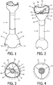
- Figures 1 and 2 show a first embodiment of a stick-shaped device 1 for use in a blender, carrying a rotatably arranged knife 10 at an end 2 thereof, and comprising a tool cage 20 for partially covering the knife 10.
- a complete blender is not shown in the figures, as the present invention particularly focuses on the device 1 comprising the knife 10 and the tool cage 20.
- the stick-shaped device 1 can be made of stainless steel, for example, or plastic, as known per se.
- the device 1 accommodates an elongated shaft 11 for supporting and rotating the knife 10, as can be seen in figure 5 .
- the knife 10 is arranged at one end 12 of the shaft 11, whereas another end (not shown) of the shaft 11 is adapted to be connected to driving means such as a motor (not shown) of the blender.
- the knife 10 is usually made of stainless steel, and, in the shown example, has two diametrically arranged blades 13, 14 in a more or less flat appearance, wherein each of the blades 13, 14 has a cutting edge 15 extending along a substantial portion of a length of the blades 13, 14.
- the number of blades 13, 14 of the knife 10 does not necessarily need to be two, but may also be three, for example. In any case, when the knife 10 is rotated, a local flow of food is realized, wherein the cutting edges 15 of the blades 13, 14 of the knife 10 move the food and cut through the food.
- an operational orientation of the stick-shaped device 1 is an orientation in which the knife 10 is at a downside, as shown in figure 1 .
- terms such as “bottom” and “top” are related to this orientation.
- Figure 3 shows a bottom view of the tool cage 20 and the knife 10, and figure 4 shows a top view of the tool cage 20.
- the tool cage 20 is shaped like a hollow cylinder, which has an open end 21 for allowing access to the knife 10.
- the tool cage 20 is also open, so that a portion of a support stick 3 of the stick-shaped device 1 can extend into the tool cage 20 from the side of that other end 22, as can be seen in figure 5 .
- the first end 21 of the tool cage 20 will be referred to as bottom end 21, and the second end 22 of the tool cage 20 will be referred to as top end 22.
- a longitudinal axis of the tool cage 20 is depicted in figure 5 by means of a dash-and-dot line, and is indicated by means of reference numeral 23.
- the support stick 3 and the tool cage 20 may be produced as two individual pieces which can be interconnected, but it is also possible to produce the support stick 3 and the tool cage 20 as a single combined piece.
- the tool cage 20 has a tapering shape, wherein dimensions of a cross-sectional area of the tool cage 20 are the largest at the bottom end 21, and wherein dimensions of a cross-sectional area of the tool cage 20 are the smallest at the top end 22.
- Another notable feature of the tool cage 20 is that the tool cage 20 has a triangular shape when being viewed from the direction in which the longitudinal axis 23 extends, as can be seen in figures 3 and 4 . In the shown example, both an inner surface 24 of the tool cage 20 and an outer surface 25 of the tool cage 20 are triangular about the longitudinal axis 23.
- an imaginary circle is depicted by means of a dash-and-dot line, in order to clearly illustrate how the shape of the surfaces 24, 25 is non-circular, particularly triangular.
- the tool cage 20 On the basis of the triangular shape, the tool cage 20 has a threefold rotational symmetry about the longitudinal axis 23.
- the tool cage 20 has an overall smooth appearance on the basis of the fact that corners 26 of the triangular shape are chosen such as to be rounded, and sides 27 of the triangular shape are chosen such as to be curved, wherein the inner surface 24 is concave, and the outer surface 25 is convex.
- Figure 5 clearly illustrates a preferred shape of the knife 10 and a preferred positioning of the knife 10 on the support stick 3 and inside the tool cage 20.
- the longitudinal axis 23 of the tool cage 20 coincides with a longitudinal axis of the shaft 11 for rotating the knife 10, i.e. an axis about which the knife 10 is rotatable.
- the blades 13, 14 of the knife 10 have an orientation which deviates to some extent from an orientation at right angles with the axis 23. Consequently, the blades 13, 14 are not exactly horizontal in the operational orientation of the stick-shaped device 1.
- one blade 13 is inclined somewhat upward, and another blade 14 is inclined somewhat downward with respect to a central portion 16 of the knife 10 where the knife 10 is attached to the shaft 11.
- tip portions 17, 18 of the blades 13, 14 rotate in different planes.
- a cross-sectional area of the tool cage 20 at a plane more to the bottom side is larger than a cross-sectional area of the tool cage 20 at a plane more to the top side, due to the tapering shape of the tool cage 20.
- the level of the relatively small cross-sectional area is the highest level of the knife 10, i.e. the level where the tip portion 18 which is more to the top side of the tool cage 20 is located, and the level of the relatively large cross-sectional area is the lowest level of the knife 10, i.e. the level where the tip portion 17 which is more to the bottom side of the tool cage 20 is located.
- Figures 8-10 relate to a second embodiment of the stick-shaped device 1 according to the present invention.
- a difference between the first embodiment as described in the foregoing on the basis of figures 1-7 and the second embodiment resides in the shape of the tool cage 20.
- the tool cage 20 has a square shape when being viewed from the direction in which the longitudinal axis 23 extends.
- both an inner surface 24 of the tool cage 20 and an outer surface 25 of the tool cage 20 are square about the longitudinal axis 23.
- an imaginary circle is depicted by means of a dash-and-dot line, in order to clearly illustrate how the shape of the surfaces 24, 25 is non-circular, particularly square.
- the tool cage 20 On the basis of the square shape, the tool cage 20 has a fourfold rotational symmetry about the longitudinal axis 23.
- the tool cage 20 has an overall smooth appearance on the basis of the fact that corners 26 of the square shape are chosen such as to be rounded, and sides 27 of the square shape are chosen such as to be curved, wherein the inner surface 24 is concave, and the outer surface 25 is convex.
- FIGS 8 and 10 an option of having a closing plate 30 inside the tool cage 20, at a position behind the knife 10, preferably a position right behind the knife 10, is illustrated. Due to the presence of the closing plate 30, a top portion of the tool cage 20 is closed, whereby it is prevented that food to be processed can flow to that top portion. In this way, cleanability of the tool cage 20 is enhanced, as it is not possible for food to accumulate in the top portion. Furthermore, on the basis of the presence of the closing plate 30, a working space of the tool cage 20 is decreased, and the performance of the combination of the knife 10 and the tool cage 20 is improved.
- the closing plate 30 has a planar appearance, as is the case in the shown example.
- a dimensionless characteristic value is determined in respect of the stick-shaped device 1, particularly the combination of the knife 10 and the tool cage 20, and this value is compared with a predetermined range of values in order to find out whether an effective performance and good blending results can be expected.
- the range of the dimensionless characteristic value is a range from 7 to 18.
- the geometry of the device 1 has a characteristic value which is within this range, effective functioning of the device 1 can be guaranteed.
- a possibility for predicting whether a combination of a rotatably arranged tool/knife 10 and a tool cage 20 for partially covering the tool/knife 10 can be expected to realize good blending results in an acceptable period of time is not known from the art.
- the dimensionless characteristic value as defined in the foregoing can be determined and then compared to the range as mentioned. Only if the dimensionless characteristic value is inside the range, it is concluded with certainty that proper functioning of the device 1 can be expected.
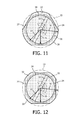
- Figures 11 and 12 serve to illustrate the various factors which are used for determining the dimensionless characteristic value, for the triangular shape of the inner surface 24 of the tool cage 20 about the longitudinal axis 23, and the square shape of the inner surface 24 of the tool cage 20 about the longitudinal axis 23, respectively.
- the shape of the inner surface 24, which is a (rotation) symmetrical shape in this case, with rounded corners 26 and straight sides 27, is shown.
- An imaginary circle being centrally positioned about the longitudinal axis 23 and touching the inner surface 24 while having a minimum radius is indicated by reference numeral 31.
- Protruding areas which are outside of the circle as mentioned, and which can also be denoted as lobes, for example, are indicated by reference numeral 32.
- An imaginary circle being centrally positioned about the longitudinal axis 23 and touching the inner surface 24 while having a maximum radius is indicated by reference numeral 33.
- An imaginary circle delimiting an area which is covered by the tool/knife 10 is indicated by reference numeral 34.
- a maximum radius of the tool/knife 10, which is the radius of the area as mentioned, is indicated by an arrow 35.
- a maximum inner radius of the tool cage 20, which is the radius of the imaginary circle 33 being centrally positioned about the longitudinal axis 23 and touching the inner surface 24 while having a maximum radius, is indicated by an arrow 36.
- a minimum inner radius of the tool cage 20, which is the radius of the imaginary circle 31 being centrally positioned about the longitudinal axis 23 and touching the inner surface 24 while having a minimum radius, is indicated by an arrow 37.
- a device 1 for use in a blender comprises a rotatably arranged tool 10 for moving through food to be processed by means of the blender, and a tool cage 20 for partially covering the tool 10.
- the tool cage 20 is shaped like a hollow cylinder having a longitudinal axis 23 and an inner surface 24 with exclusively non-convex areas, wherein a cross-sectional shape of the tool cage 20 deviates from a circular shape and has at least one protruding area 32.
- the tool can be a knife 10 comprising at least one blade 13, 14.
- the inner surface 24 of the tool cage 20 can have a triangular shape or a square shape about the longitudinal axis 23, so that sufficiently large areas for receiving and discharging food to be processed are realized at the inside of the tool cage 20, which are near to the tool 10, and suitable areas for allowing the tool 10 to act on the food are realized as well.
- the triangular shape or the square shape can be such that the inner surface 24 of the tool cage 20 only has smooth concave portions, wherein it is possible to let food processing actions take place at a minimum level of power consumption.
- An outer surface 25 of the tool cage 20 can have a triangular shape or a square shape about the longitudinal axis 23 as well.
- the triangular shape or the square shape it is possible to have an overall smooth appearance of the tool cage 20, as a result of which a manufacturing process of the tool cage 20 may be easy and therefore cheap, and it may be easy to clean the tool cage 20.
- the triangular shape or the square shape at the outside it is easy to reach food located in corners of a food container or the like.
- a dimensionless characteristic value and a range for the value are defined for predicting quality of performance of the device 1 according to the present invention.
Landscapes
- Engineering & Computer Science (AREA)
- Mechanical Engineering (AREA)
- Food Science & Technology (AREA)
- Food-Manufacturing Devices (AREA)
- Mixers Of The Rotary Stirring Type (AREA)
- Formation And Processing Of Food Products (AREA)
Abstract
Description
- The present invention relates to a device for use in a blender, comprising a rotatably arranged tool for moving through food to be processed by means of the blender, and a tool cage for partially covering the tool, wherein the tool cage is shaped like a hollow cylinder having a longitudinal axis and an inner surface which exclusively comprises areas with a non-convex general shape, wherein a cross-sectional shape of the tool cage, i.e. a shape of an imaginary section perpendicular to the longitudinal axis, deviates from a circular shape and has at least one protruding area which is outside of an imaginary circle being positioned inside the tool cage and touching the inner surface while having a minimum radius.
- The present invention also relates to a blender, comprising a device as mentioned, and means for driving the tool which is part of the device.
- In general, a blender is a household appliance which is adapted to be used for processing food, particularly mixing, comminuting, and/or aerating food. To this end, the blender comprises one or more rotatably arranged tools such as whisks or knives for moving through the food. In one known type of blender, which is known as stick blender, a rotatably arranged knife is applied, which usually has two diametrically arranged blades in a more or less flat appearance, like a propeller. Furthermore, a stick blender has a housing for accommodating components of the blender, including means such as a motor for driving the knife, and an elongated, stick-shaped device carrying the knife at an end thereof. The housing is shaped such that it is possible for a user to take hold of the blender in a very convenient manner, and to have a firm grip on the blender during food processing actions. In use, the user inserts the stick-shaped device in a quantity of food, with the knife down, wherein the food is processed as the knife rotates. The user may move the blender during a food processing action, so as to continually change the location of the rotating knife in the food.
- In order to avoid injuries of the user and/or damage to an inner surface of a container in which food to be processed is present, it is desirable to have the knife covered as much as possible, however, without deteriorating the functionality of the knife. To this end, a suitable cover is used, which is referred to as tool cage, and which has an opening for allowing the knife to reach the food, but which prevents a user from freely touching the knife. Furthermore, in a more general sense, the use of a tool cage greatly improves the effectiveness of the knife and the performance of the blender. A standard orientation of a stick blender is a vertical orientation with the knife at a downside, and in such an orientation, the tool cage is at a downside of the blender as well, and serves for preventing a user from touching the knife from the side. Normally, the tool cage is shaped like a tapered, hollow cylinder having an open end, like a cup, a bell, a bowl, a tulip, an umbrella, or the like. The tool cage may be removably arranged for cleaning purposes, for example.
- A tool cage as mentioned, suitable for use in a hand-held blender or mixer, is known from
WO 99/48411 - In
US 5,639,034 , another tool cage is disclosed, which includes an inner surface having a cross-section which takes the form of a substantially regular polygon with at least five and preferably fifteen sides. On the basis of this particular shape of the inner surface of the tool cage, food materials are comminuted in the tool cage particularly rapidly. After the food impinges against the inner surface, the polygonal profile causes the food to be deflected from the inner surface and to be directed back to the area where the knife is for further comminution. - It is an object of the present invention to provide another design for a tool cage than the known designs, which, among other things, allows for effective food processing actions, provides for an improved reachability of food in corners of containers, allows for an easy manufacturing process, allows for easy cleaning, provides for improved handling by a user, and contributes to having reduced energy consumption in the blender in which it is used. The object is achieved by means of a device for use in a blender, comprising a rotatably arranged tool for moving through food to be processed by means of the blender, and a tool cage for partially covering the tool, wherein the tool cage is shaped like a hollow cylinder having a longitudinal axis and an inner surface which exclusively comprises areas with a non-convex general shape, wherein a cross-sectional shape of the tool cage deviates from a circular shape and has at least one protruding area which is outside of an imaginary circle being centrally positioned about the longitudinal axis and touching the inner surface while having a minimum radius, and wherein the device has a geometry according to the following requirement:
7 ≤ S ≤ 18,
in which S is a dimensionless characteristic value which is defined by the following formula:
in which Rtool represents the maximum radius of the tool, Rmax represents the maximum inner radius of the tool cage, measured at a highest level of the tool, Rmin represents the minimum inner radius of the tool cage, measured at the highest level of the tool, and N represents the number of protruding areas. - According to the present invention, a device with a tool cage having an inner surface which exclusively comprises areas with a non-convex general shape is provided. Hence, the inner surface of the tool cage only has portions with a straight and/or concave general shape, on the basis of which a good cleanability of the inner surface is obtained. Also, it is achieved that a flow of food inside the tool cage can take place in a smooth and unhindered manner, due to the absence of convex portions of the inner surface in general. Furthermore, the tool cage is shaped like a hollow cylinder. In the context of the present invention, the term cylinder is not limited to the most common concept of this term, which involves a straight longitudinal axis and a circular circumference about the longitudinal axis. A notable deviation from the most common concept resides in the fact that the circumference of the tool cage is non-circular, in other words, the fact that the circumference can have any shape but a circular one. Other deviations are possible as well if so desired, as long as the geometry requirements as defined in the preceding paragraph are taken into account. In respect of the longitudinal axis, it is noted that this axis may be the same as an axis of symmetry in cases where the cylinder has a circumference which is rotation symmetrical.
- Furthermore, a cross-sectional shape of the tool cage deviates from a circular shape in that this shape has at least one protruding area which is outside of an imaginary circle being centrally positioned about the longitudinal axis and touching the inner surface while having a minimum radius. The protruding area has an important function in allowing transport of food in and out of the tool cage, among other things.
- Various designs of the tool cage are known in the art, including designs having an inner surface with exclusively non-convex areas, wherein a cross-sectional shape of the tool cage deviates from a circular shape and has at least one protruding area which is outside of an imaginary circle being positioned inside the tool cage and touching the inner surface while having a minimum radius. For example, such a design is known from
US 5,639,034 , in view of the fact that this document discloses a tool cage having a polygonal profile with a number of sides in a range of five to fifteen, as explained in the foregoing. However, when a certain design is considered, it is not prima facie clear if that design will actually be capable of meeting requirements in respect of good performance. In other words, it is not prima facie clear if that design will contribute to a fast and effective blending process and good blending results. According to the present invention, in order to overcome this problem, a dimensionless characteristic value is introduced, and a range is determined for this value, so that it is possible to predict the effectiveness of certain designs, namely by determining if the characteristic values of the designs are inside or outside of the range. In fact, the dimensionless characteristic value can be regarded as a performance indication number. - In particular, the present invention proposes to use a dimensionless characteristic value which defines the geometry of a tool cage on the basis of a relation between a cross-sectional area which is used for blending, i.e. a cross-sectional area which is covered by the rotatably arranged tool, and a cross-sectional area of a protruding area, at the highest level of the tool, i.e. the level which is both reached by the tool inside the tool cage and the furthest remote from an open end of the tool cage, for the total number of protruding areas. As has been noted in the foregoing, this dimensionless characteristic value is defined by the following formula:

in which Rtool represents the maximum radius of the tool, Rmax represents the maximum inner radius of the tool cage, measured at a highest level of the tool, Rmin represents the minimum inner radius of the tool cage, measured at the highest level of the tool, and N represents the number of protruding areas. In a practical case, the cross-sectional shape of the tool cage can have a rotational symmetry about the longitudinal axis, wherein the number of protruding areas can be easily determined, and may be the same as the number associated with the rotational symmetry. - For the purpose of applying the formula, the maximum radius of the tool is found on the basis of a largest radial dimension of the tool, i.e. a largest distance between a tip of the tool and an axis about which the tool is rotatable, measured in an imaginary plane which is perpendicular to the axis as mentioned. The maximum inner radius of the tool cage is found on the basis of the radius of the largest imaginary circle being centrally positioned about the longitudinal axis and touching the inner surface while having a maximum radius, measured in an imaginary plane which is perpendicular to the longitudinal axis, i.e. a cross-sectional plane, and which is located at the highest level of the tool. Likewise, the minimum inner radius of the tool cage is found on the basis of the radius of the smallest imaginary circle being centrally positioned about the longitudinal axis and touching the inner surface while having a minimum radius, measured in an imaginary plane which is perpendicular to the longitudinal axis, and which is located at the highest level of the tool.
- In view of the fact that it is possible for every device comprising a tool and a tool cage having an inner surface with exclusively non-convex areas and at least one protruding area as defined in the foregoing to determine the values of the maximum radius of the tool, the maximum inner radius of the tool cage at the highest level of the tool, the minimum inner radius of the tool cage at the highest level of the tool, and the number of protruding areas, it is possible to determine the value of the dimensionless characteristic value. A suitable range for the dimensionless characteristic value has been found on the basis of tests which were performed in the context of the present invention, namely by checking for devices of various designs whether a good blending performance, a low suction force on the food to be processed, and a low degree of splashing were obtained, or not.
- In particular, in the context of the present invention, two different devices were tested, and it was found that both devices meet the requirements as to blending performance, suction force, and splashing. A first test device is a device comprising a tool cage of which the inner surface has a triangular shape about the longitudinal axis, wherein a wall thickness of the tool cage is more or less the same for all locations on the tool cage, so that the outer surface is triangular about the longitudinal axis as well. The triangular shape is chosen such that the tool cage has a threefold rotational symmetry about the longitudinal axis. Furthermore, the corners of the triangular shape are rounded, and the sides of the triangular shape are curved outwardly and thereby shaped like a segment of a circle, as it were. The maximum radius of the tool of the first test device is 25.15 mm, the maximum inner radius of the tool cage, measured at the highest level of the tool is 28.15 mm, and the minimum inner radius of the tool cage, measured at the highest level of the tool is 26.15 mm. As a consequence, the design of the first test device involves a dimensionless characteristic value having a value of 17.5. A second test device has the same characteristics as the first test device, with the exception of the maximum inner radius of the tool cage at the highest level of the tool, which is 30.65 mm. Hence, the design of the second test device involves a dimensionless characteristic value having a value of 7.4. On the basis of the particulars and performance of the devices which were tested, it is concluded that a range from 7 to 18 in respect of the dimensionless characteristic value is a practical range for guaranteeing/predicting a fast and effective blending process and good blending results.
- In respect of the dimensionless characteristic value, it is noted that this value increases when the number of protruding areas increases, assuming otherwise equal design particulars, i.e. equal values in respect of the other determining factors of the dimensionless characteristic value. For example, in the case of a device having four protruding areas instead of three, while having the same values in respect of the maximum radius of the tool, the maximum inner radius of the tool cage, and the minimum inner radius of the tool cage as the first test device, the dimensionless characteristic value is 23.3, which is outside of the range. In view thereof, it is concluded that a fast and effective blending process and good blending results cannot be guaranteed.
- Furthermore, from a comparison between the first test device and the second test device, it appears that the dimensionless characteristic value decreases when the maximum inner radius of the tool cage increases, assuming otherwise equal design particulars. This also implies that, assuming a certain minimum inner radius of the tool cage, a larger difference between the maximum inner radius of the tool cage and the minimum inner radius of the tool cage involves a lower dimensionless characteristic value. In other words, assuming a certain minimum inner radius of the tool cage, there is a maximum to the maximum inner radius of the tool cage, i.e. the extent of undulation of the tool cage on the basis of the presence of the protruding areas, when it comes to guaranteeing/predicting a fast and effective blending process and good blending results.
- When the design particulars of the second test device are taken as a basis, and the minimum inner radius of the tool cage is chosen such as to be 28.65 mm, the dimensionless characteristic value appears to have an increased value as well, namely 16.0. This also implies that, assuming a certain maximum radius of the tool, a larger difference between the minimum inner radius of the tool cage and the maximum radius of the tool involves a higher dimensionless characteristic value. In other words, assuming a certain maximum radius of the tool, there is a maximum to the minimum inner radius of the tool cage, i.e. the space which is available around the area covered by the tool, when it comes to guaranteeing/predicting a fast and effective blending process and good blending results.
- In respect of the difference between the maximum inner radius of the tool cage and the minimum inner radius of the tool cage, it is noted that a range of 2.0 mm to 5.0 mm is a practical range, wherein a value of 3.0 mm is a preferred value. In respect of the difference between the minimum inner radius of the tool cage and the maximum radius of the tool, it is noted that a range of 1.0 mm to 5.0 mm is a practical range, wherein a value of 2.0 mm is a preferred value. In respect of the maximum radius of the tool, it is noted that a range of 20.0 mm to 30.0 mm is a practical range, wherein a value of 25.0 mm is a preferred value. A preferred value of the dimensionless characteristic value is about 17.
- In a preferred embodiment of the device according to the present invention, the tool cage has one of a triangular shape about the longitudinal axis, wherein three protruding areas are constituted by the three corners of the triangular shape, and a square shape about the longitudinal axis, wherein four protruding areas are constituted by the four corners of the square shape. Naturally, in order to guarantee usefulness of the device, the other design particulars should be chosen such that a practical dimensioning of the device is obtained on the one hand and a dimensionless characteristic value which is inside the range of 7 to 18 is obtained on the other hand.
- In the following, further details are given with respect to the tool cage of which the inner surface has a triangular shape about the longitudinal axis, which will hereinafter be referred to as triangular tool cage. The triangular tool cage is especially suitable to be used with a rotatably arranged knife having two diametrically arranged blades with cutting edges, i.e. a bar-shaped knife, in which case the tool cage is also referred to as bar cage. When the triangular tool cage is used as mentioned, a cage geometry which is highly efficient in respect of food processing is combined with a smallest possible cage volume, wherein sufficiently large feeding/discharging areas and food cutting areas are present near to the cutting edges of the knife. In particular, feeding/discharging can primarily take place in corner areas of the triangular shape, while cutting can primarily take place along the sides of the triangular shape. To this end, it is advantageous if the dimensions of the tool cage are adapted to the dimensions of the knife in such a way that only a small gap is present between ends of the knife and central portions of the sides of the triangular shape, i.e. the positions associated with the minimum inner radius of the tool cage. The tool cage can have smooth inner and outer surfaces, especially when a triangular shape with rounded corners is chosen, which are very easy to produce in various materials, including plastic materials or sheet materials. The design of the inner surface is an overall concave design. Preferably, the inner surface is free from undercuts/ribs in order to have optimal cleanability of the surface and to avoid hindrance of a flow of food inside the tool cage, although it is in principle possible to have such locally arranged members in/on the surface which is non-convex on a general level. All in all, an optimal flow of food to be processed can be obtained in the tool cage with a minimum of manufacturing efforts, which leads to reduction of costs.
- Furthermore, the triangular shape of the inner surface of the tool cage allows for a triangular shape of an outer surface of the tool cage as well, so that corners of food containers can easily be reached. Smooth inner and outer surfaces allow for easy cleaning of the tool cage. Compared to conventional designs of a tool cage involving a circle shape, whether undulating or not, the design involving a triangular shape is extremely compact, cheap, and yet very functional and practical.
- Preferably, like conventional tool cages, the triangular tool cage is shaped like a cup, a bell, a bowl, a tulip, an umbrella, or the like. In general, it is preferred for the tool cage to have a tapering shape, wherein the length of a circumference of the inner surface is different for different positions along the longitudinal axis.
- In respect of the triangular shape, it is noted that this shape may be such that the tool cage has a threefold rotational symmetry about the longitudinal axis. The three sides of the triangular shape may be concavely curved, so that dimensions of a space between the sides and the tool decrease and increase gradually, as seen in a direction of rotation of the tool. The triangular inner surface may have rounded corners, so that an overall smooth appearance of the tool cage is obtained, and food can easily move in and out of the corner areas without getting stuck there.
- An outer surface of the tool cage may be shaped in a similar manner as the inner surface, wherein a wall thickness of the tool cage may be more or less the same for all locations on the tool cage. Hence, the outer surface may be triangular about the longitudinal axis. As has already been mentioned in the foregoing, this offers the advantage of improved reachability of corners of food containers. Furthermore, the three sides of the triangular outer surface may have a convexly curved shape, and may have rounded corners, so that an overall smooth appearance without any sharp edge is obtained.
- Many aspects as described in the foregoing are also applicable to a situation in which the inner surface of the tool cage has a square shape about the longitudinal axis. Among other things, it is advantageous if the corners of the square shape are rounded. Also, it is practical for the tool cage to have a fourfold symmetry about the longitudinal axis. When the outer surface of the tool cage has a square shape about the longitudinal axis as well, it is advantageous for the corners of the square shape to be rounded, and for the sides of the square shape to be convexly curved.
- Like in conventional situations, it is possible for a brim of the tool cage, which is present at an open end of the tool cage, to have an undulating configuration. In such a case, when the tool cage is put down on a surface such as a bottom of a food container, food can pass in and out of an inside space of the tool cage at the locations where recessed brim portions are present, while the tool cage contacts the surface through projecting brim portions. Furthermore, it is preferred if the longitudinal axis of the tool cage coincides with an axis about which the tool is rotatable, so that a balanced and smooth blending process can be ensured.
- In order to have improved cleanability of the tool cage and a good performance of the combination of the tool and the tool cage, a closing plate can be used for closing off a portion of the tool cage which is present behind the tool. Thus, such a closing plate is intended to be arranged inside the tool cage, at a position behind the tool, preferably a position right behind the tool.
- The tool may be a knife comprising at least one blade, and an orientation of the blade may deviate to a relatively small extent from an orientation at right angles with an axis about which the knife is rotatable. In this way, which is known per se, it is achieved that during rotation, the knife repetitively passes several sections of the tool cage having different dimensions, assuming a tapering shape of the tool cage. Having variations of dimensions of the space between ends of the knife and the inner surface of the tool cage is advantageous in view of processes such as allowing food to enter, cutting through the food, drawing in air to the food, and discharging the food.
- As has already been mentioned in the foregoing, the present invention relates to a device for use in a blender, wherein a tool cage which is part of the device is designed according to specific requirements. In particular, the requirements relate to the cross-sectional shape of the tool cage, and dimensions of the tool cage and a tool which is part of the device as well, wherein a dimensionless characteristic value and a range of that value are defined. Furthermore, the present invention relates to a blender comprising the device and means for driving the tool. The device normally has an elongated shape when the blender is a stick blender. The device may be detachable from other components of the blender, particularly a housing which is used for allowing a user to take hold of the blender, and which accommodates means such as a motor for driving the tool, but that does not alter the fact that it is also possible for the device to be an integral part of a blender.
- The above-described and other aspects of the present invention will be apparent from and elucidated with reference to the following detailed description of two embodiments of a stick-shaped device for use in a blender, carrying a rotatably arranged knife at an end thereof, and comprising a tool cage for partially covering the knife and delimiting a working space of the knife in order to realize both effective flows of food to be processed and an effective impact of the knife on the food.
- The present invention will now be explained in greater detail with reference to the figures, in which equal or similar parts are indicated by the same reference signs, and in which:
-
Figures 1 and 2 diagrammatically show perspective views of a first embodiment of a stick-shaped device for use in a blender, carrying a rotatably arranged knife at an end thereof, and comprising a tool cage for partially covering the knife; -
Figure 3 diagrammatically shows a bottom view of the tool cage and the knife; -
Figure 4 diagrammatically shows a top view of the tool cage; -
Figure 5 diagrammatically shows a longitudinal section of an end portion of the stick-shaped device; -
Figure 6 diagrammatically shows a top view of a cross-section indicated as A-A infigure 5 ; -
Figure 7 diagrammatically shows a top view of a cross-section indicated as B-B infigure 5 , wherein the knife is shown for better visualization; -
Figure 8 shows a bottom view of the tool cage and the knife of a second embodiment of a stick-shaped device for use in a blender; -
Figure 9 diagrammatically shows a top view of the tool cage; -
Figure 10 diagrammatically shows a perspective view of an end portion of the stick-shaped device; -
Figure 11 serves to illustrate a number of determining factors of a dimensionless characteristic value of the design of the first embodiment of the stick-shaped device; and -
Figure 12 serves to illustrate a number of determining factors of a dimensionless characteristic value of the design of the second embodiment of the stick-shaped device. -
Figures 1 and 2 show a first embodiment of a stick-shapeddevice 1 for use in a blender, carrying a rotatably arrangedknife 10 at anend 2 thereof, and comprising atool cage 20 for partially covering theknife 10. For sake of completeness, it is noted that a complete blender is not shown in the figures, as the present invention particularly focuses on thedevice 1 comprising theknife 10 and thetool cage 20. - The stick-shaped
device 1 can be made of stainless steel, for example, or plastic, as known per se. Thedevice 1 accommodates anelongated shaft 11 for supporting and rotating theknife 10, as can be seen infigure 5 . Theknife 10 is arranged at oneend 12 of theshaft 11, whereas another end (not shown) of theshaft 11 is adapted to be connected to driving means such as a motor (not shown) of the blender. - The
knife 10 is usually made of stainless steel, and, in the shown example, has two diametrically arrangedblades blades cutting edge 15 extending along a substantial portion of a length of theblades blades knife 10 does not necessarily need to be two, but may also be three, for example. In any case, when theknife 10 is rotated, a local flow of food is realized, wherein the cutting edges 15 of theblades knife 10 move the food and cut through the food. - It is noted that an operational orientation of the stick-shaped
device 1 is an orientation in which theknife 10 is at a downside, as shown infigure 1 . In this text, terms such as "bottom" and "top" are related to this orientation. During use for performing a food processing action, the stick-shapeddevice 1 is held in a quantity of food with thetool cage 20 down, and with theknife 10 performing a rotating movement. -
Figure 3 shows a bottom view of thetool cage 20 and theknife 10, andfigure 4 shows a top view of thetool cage 20. Infigures 1 and 2 , it can be seen that thetool cage 20 is shaped like a hollow cylinder, which has anopen end 21 for allowing access to theknife 10. At anotherend 22, thetool cage 20 is also open, so that a portion of asupport stick 3 of the stick-shapeddevice 1 can extend into thetool cage 20 from the side of thatother end 22, as can be seen infigure 5 . In the following, for sake of clarity, thefirst end 21 of thetool cage 20 will be referred to asbottom end 21, and thesecond end 22 of thetool cage 20 will be referred to astop end 22. A longitudinal axis of thetool cage 20 is depicted infigure 5 by means of a dash-and-dot line, and is indicated by means ofreference numeral 23. Thesupport stick 3 and thetool cage 20 may be produced as two individual pieces which can be interconnected, but it is also possible to produce thesupport stick 3 and thetool cage 20 as a single combined piece. - Particularly, the
tool cage 20 has a tapering shape, wherein dimensions of a cross-sectional area of thetool cage 20 are the largest at thebottom end 21, and wherein dimensions of a cross-sectional area of thetool cage 20 are the smallest at thetop end 22. Another notable feature of thetool cage 20 is that thetool cage 20 has a triangular shape when being viewed from the direction in which thelongitudinal axis 23 extends, as can be seen infigures 3 and 4 . In the shown example, both aninner surface 24 of thetool cage 20 and anouter surface 25 of thetool cage 20 are triangular about thelongitudinal axis 23. Infigures 2, 3, and 4 , an imaginary circle is depicted by means of a dash-and-dot line, in order to clearly illustrate how the shape of thesurfaces tool cage 20 has a threefold rotational symmetry about thelongitudinal axis 23. In the shown example, thetool cage 20 has an overall smooth appearance on the basis of the fact thatcorners 26 of the triangular shape are chosen such as to be rounded, and sides 27 of the triangular shape are chosen such as to be curved, wherein theinner surface 24 is concave, and theouter surface 25 is convex. - On the basis of the triangular shape and the overall smooth appearance as mentioned, it is very well possible to reach corners of food containers, to avoid damage to an inner surface of such containers, and to clean the
tool cage 20, to mention a few advantages of the design of thetool cage 20 according to the present invention. Furthermore, at thecorners 26 of the triangular shape, food to be processed can be received and discharged, whereas the food can be compacted near thesides 27 of the triangular shape, so that effective flows of food can be obtained during operation of the blender and immersion of at least the area of the blender where theknife 10 is located in an amount of food, and effective food processing actions can be realized. In view of the fact that theinner surface 24 of thetool cage 20 has an overall concave appearance, and does not comprise any convex portions, consumption of power needed for driving theknife 10 is reduced to a minimum. - In
figures 1, 2 and5 , it can be seen that it is possible to have an undulating shape for abrim 28 of thetool cage 20, i.e. an outer edge of thetool cage 20 at thebottom end 21 thereof. In this way, it is achieved that a number of openings are present in thetool cage 20 when thetool cage 20 is held against a surface such as a bottom of a food container, which openings allow food to flow in and out of thetool cage 20, and which facilitate movements of thetool cage 20 through the food, especially sideward movements. It is understood that the openings as mentioned are present at the positions of recessedportions 29 of the undulating shape. -
Figure 5 clearly illustrates a preferred shape of theknife 10 and a preferred positioning of theknife 10 on thesupport stick 3 and inside thetool cage 20. In the first place, it is noted that thelongitudinal axis 23 of thetool cage 20 coincides with a longitudinal axis of theshaft 11 for rotating theknife 10, i.e. an axis about which theknife 10 is rotatable. In the second place, it is noted that theblades knife 10 have an orientation which deviates to some extent from an orientation at right angles with theaxis 23. Consequently, theblades device 1. Instead, oneblade 13 is inclined somewhat upward, and anotherblade 14 is inclined somewhat downward with respect to acentral portion 16 of theknife 10 where theknife 10 is attached to theshaft 11. In this way, it is achieved thattip portions blades tool cage 20 at a plane more to the bottom side is larger than a cross-sectional area of thetool cage 20 at a plane more to the top side, due to the tapering shape of thetool cage 20. This is clearly illustrated by means offigures 6 and 7 , whereinfigure 6 shows the relatively small cross-sectional area, and whereinfigure 7 shows the relatively large cross-sectional area. In comparison with a horizontal orientation, a larger area inside thetool cage 20 is involved in food cutting processes to be performed by means of theknife 10 when thetip portions blades tool cage 20, whereby a more effective food cutting process can be realized. For sake of completeness, it is noted that the level of the relatively small cross-sectional area is the highest level of theknife 10, i.e. the level where thetip portion 18 which is more to the top side of thetool cage 20 is located, and the level of the relatively large cross-sectional area is the lowest level of theknife 10, i.e. the level where thetip portion 17 which is more to the bottom side of thetool cage 20 is located. -
Figures 8-10 relate to a second embodiment of the stick-shapeddevice 1 according to the present invention. A difference between the first embodiment as described in the foregoing on the basis offigures 1-7 and the second embodiment resides in the shape of thetool cage 20. In particular, in the second embodiment, thetool cage 20 has a square shape when being viewed from the direction in which thelongitudinal axis 23 extends. In the shown example, both aninner surface 24 of thetool cage 20 and anouter surface 25 of thetool cage 20 are square about thelongitudinal axis 23. Infigures 8-10 , an imaginary circle is depicted by means of a dash-and-dot line, in order to clearly illustrate how the shape of thesurfaces tool cage 20 has a fourfold rotational symmetry about thelongitudinal axis 23. In the shown example, thetool cage 20 has an overall smooth appearance on the basis of the fact thatcorners 26 of the square shape are chosen such as to be rounded, and sides 27 of the square shape are chosen such as to be curved, wherein theinner surface 24 is concave, and theouter surface 25 is convex. - In
figures 8 and 10 , an option of having a closingplate 30 inside thetool cage 20, at a position behind theknife 10, preferably a position right behind theknife 10, is illustrated. Due to the presence of theclosing plate 30, a top portion of thetool cage 20 is closed, whereby it is prevented that food to be processed can flow to that top portion. In this way, cleanability of thetool cage 20 is enhanced, as it is not possible for food to accumulate in the top portion. Furthermore, on the basis of the presence of theclosing plate 30, a working space of thetool cage 20 is decreased, and the performance of the combination of theknife 10 and thetool cage 20 is improved. Preferably, the closingplate 30 has a planar appearance, as is the case in the shown example. - According to the present invention, a dimensionless characteristic value is determined in respect of the stick-shaped
device 1, particularly the combination of theknife 10 and thetool cage 20, and this value is compared with a predetermined range of values in order to find out whether an effective performance and good blending results can be expected. - The dimensionless characteristic value is found by using the following formula:

in which Rtool represents the maximum radius of the tool/knife 10, Rmax represents the maximum inner radius of thetool cage 20, measured at the highest level of the tool/knife 10, Rmin represents the minimum inner radius of thetool cage 20, measured at the highest level of the tool/knife 10, and N represents the number of protruding areas, i.e. the number of areas which are outside of an imaginary circle being centrally positioned about thelongitudinal axis 23 and touching theinner surface 24 of thetool cage 20 while having a minimum radius. - The range of the dimensionless characteristic value is a range from 7 to 18. When the geometry of the
device 1 has a characteristic value which is within this range, effective functioning of thedevice 1 can be guaranteed. A possibility for predicting whether a combination of a rotatably arranged tool/knife 10 and atool cage 20 for partially covering the tool/knife 10 can be expected to realize good blending results in an acceptable period of time is not known from the art. According to the present invention, the dimensionless characteristic value as defined in the foregoing can be determined and then compared to the range as mentioned. Only if the dimensionless characteristic value is inside the range, it is concluded with certainty that proper functioning of thedevice 1 can be expected. -
Figures 11 and 12 serve to illustrate the various factors which are used for determining the dimensionless characteristic value, for the triangular shape of theinner surface 24 of thetool cage 20 about thelongitudinal axis 23, and the square shape of theinner surface 24 of thetool cage 20 about thelongitudinal axis 23, respectively. In the figures, the shape of theinner surface 24, which is a (rotation) symmetrical shape in this case, withrounded corners 26 andstraight sides 27, is shown. An imaginary circle being centrally positioned about thelongitudinal axis 23 and touching theinner surface 24 while having a minimum radius is indicated byreference numeral 31. Protruding areas which are outside of the circle as mentioned, and which can also be denoted as lobes, for example, are indicated byreference numeral 32. An imaginary circle being centrally positioned about thelongitudinal axis 23 and touching theinner surface 24 while having a maximum radius is indicated byreference numeral 33. An imaginary circle delimiting an area which is covered by the tool/knife 10 is indicated byreference numeral 34. A maximum radius of the tool/knife 10, which is the radius of the area as mentioned, is indicated by anarrow 35. A maximum inner radius of thetool cage 20, which is the radius of theimaginary circle 33 being centrally positioned about thelongitudinal axis 23 and touching theinner surface 24 while having a maximum radius, is indicated by anarrow 36. A minimum inner radius of thetool cage 20, which is the radius of theimaginary circle 31 being centrally positioned about thelongitudinal axis 23 and touching theinner surface 24 while having a minimum radius, is indicated by anarrow 37. - It will be clear to a person skilled in the art that the scope of the present invention is not limited to the examples discussed in the foregoing, but that several amendments and modifications thereof are possible without deviating from the scope of the present invention as defined in the attached claims. While the present invention has been illustrated and described in detail in the figures and the description, such illustration and description are to be considered illustrative or exemplary only, and not restrictive. The present invention is not limited to the disclosed embodiments.
- Variations to the disclosed embodiments can be understood and effected by a person skilled in the art in practicing the claimed invention, from a study of the figures, the description and the attached claims. In the claims, the word "comprising" does not exclude other steps or elements, and the indefinite article "a" or "an" does not exclude a plurality. The mere fact that certain measures are recited in mutually different dependent claims does not indicate that a combination of these measures cannot be used to advantage. Any reference signs in the claims should not be construed as limiting the scope of the present invention.
- The present invention can be summarized as follows. A
device 1 for use in a blender comprises a rotatably arrangedtool 10 for moving through food to be processed by means of the blender, and atool cage 20 for partially covering thetool 10. Thetool cage 20 is shaped like a hollow cylinder having alongitudinal axis 23 and aninner surface 24 with exclusively non-convex areas, wherein a cross-sectional shape of thetool cage 20 deviates from a circular shape and has at least one protrudingarea 32. The tool can be aknife 10 comprising at least oneblade inner surface 24 of thetool cage 20 can have a triangular shape or a square shape about thelongitudinal axis 23, so that sufficiently large areas for receiving and discharging food to be processed are realized at the inside of thetool cage 20, which are near to thetool 10, and suitable areas for allowing thetool 10 to act on the food are realized as well. The triangular shape or the square shape can be such that theinner surface 24 of thetool cage 20 only has smooth concave portions, wherein it is possible to let food processing actions take place at a minimum level of power consumption. - An
outer surface 25 of thetool cage 20 can have a triangular shape or a square shape about thelongitudinal axis 23 as well. In general, with the triangular shape or the square shape, it is possible to have an overall smooth appearance of thetool cage 20, as a result of which a manufacturing process of thetool cage 20 may be easy and therefore cheap, and it may be easy to clean thetool cage 20. Furthermore, with the triangular shape or the square shape at the outside, it is easy to reach food located in corners of a food container or the like. - A dimensionless characteristic value and a range for the value are defined for predicting quality of performance of the
device 1 according to the present invention. In particular, thedevice 1 has a geometry according to the following requirement: 7 ≤ S ≤ 18,
in which S is a dimensionless characteristic value which is defined by the following formula:
tool 10, Rmax represents the maximum inner radius of thetool cage 20, measured at the highest level of thetool 10, Rmin represents the minimum inner radius of thetool cage 20, measured at the highest level of thetool 10, and N represents the number ofprotruding areas 32. With this geometry, it is guaranteed that a fast and effective blending process and good blending results are obtained when thedevice 1 is used as part of a blender for processing food.
Claims (15)
- Device (1) for use in a blender, comprising a rotatably arranged tool (10) for moving through food to be processed by means of the blender, and a tool cage (20) for partially covering the tool (10), wherein the tool cage (20) is shaped like a hollow cylinder having a longitudinal axis (23) and an inner surface (24) which exclusively comprises areas with a non-convex general shape, wherein a cross-sectional shape of the tool cage (20) deviates from a circular shape and has at least one protruding area (32) which is outside of an imaginary circle (31) being centrally positioned about the longitudinal axis (23) and touching the inner surface (24) while having a minimum radius, and wherein the device (1) has a geometry according to the following requirement:
7 ≤ S ≤ 18,
in which S is a dimensionless characteristic value which is defined by the following formula:
in which Rtool represents the maximum radius of the tool (10), Rmax represents the maximum inner radius of the tool cage (20), measured at a highest level of the tool (10), Rmin represents the minimum inner radius of the tool cage (20), measured at the highest level of the tool (10), and N represents the number of protruding areas (32). - Device (1) according to claim 1, wherein the inner surface (24) of the tool cage (20) has one of- a triangular shape about the longitudinal axis (23), wherein three protruding areas (32) are constituted by the three corners (27) of the triangular shape, and- a square shape about the longitudinal axis (23), wherein four protruding areas (32) are constituted by the four corners (27) of the square shape.
- Device (1) according to claim 2, wherein the corners (27) of the shape of the inner surface (24) of the tool cage (20) are rounded.
- Device (1) according to claim 2, wherein the inner surface (24) of the tool cage (20) has a triangular shape about the longitudinal axis (23), and wherein the tool cage (20) has a threefold rotational symmetry about the longitudinal axis (23).
- Device (1) according to claim 2, wherein the inner surface (24) of the tool cage (20) has a square shape about the longitudinal axis (23), and wherein the tool cage (20) has a fourfold rotational symmetry about the longitudinal axis (23).
- Device (1) according to claim 1, wherein the tool cage (20) has a tapering shape along the longitudinal axis (23).
- Device (1) according to claim 1, wherein both the inner surface (24) and the outer surface (25) of the tool cage (20) have one of- a triangular shape about the longitudinal axis (23), wherein three protruding areas (32) are constituted by the three corners (27) of the triangular shape, and- a square shape about the longitudinal axis (23), wherein four protruding areas (32) are constituted by the four corners (27) of the square shape.
- Device (1) according to claim 7, wherein the sides (28) of the outer surface (25) of the tool cage (20), i.e. the portions extending between the corners (27), have a convexly curved shape.
- Device (1) according to claim 7, wherein the corners (27) of the shape of the outer surface (25) of the tool cage (20) are rounded.
- Device (1) according to claim 1, wherein a difference between the maximum inner radius of the tool cage (20) and the minimum inner radius of the tool cage (20) is in a range of 2.0 mm to 5.0 mm.
- Device (1) according to claim 1, wherein a difference between the minimum inner radius of the tool cage (20) and the maximum radius of the tool (10) is in a range of 1.0 mm to 5.0 mm.
- Device (1) according to claim 1, wherein the maximum radius of the tool (10) is in a range of 20.0 mm to 30.0 mm.
- Device (1) according to claim 1, wherein a closing plate (30) is arranged inside the tool cage (20), at a position behind the tool (10), for closing off a portion of the tool cage (20).
- Device (1) according to claim 1, wherein the tool is a knife (10) comprising at least one blade (13, 14), and wherein an orientation of the blade (13, 14) deviates to a relatively small extent from an orientation at right angles with an axis (23) about which the knife (10) is rotatable.
- Blender, comprising a device (1) according to claim 1, and means for driving the tool (10) which is part of the device (1)
Priority Applications (9)
| Application Number | Priority Date | Filing Date | Title |
|---|---|---|---|
| EP12154594.1A EP2625992B1 (en) | 2012-02-09 | 2012-02-09 | Device for use in a blender |
| BR112014019363A BR112014019363A8 (en) | 2012-02-09 | 2013-02-04 | DEVICE FOR USE IN A MIXER AND MIXER |
| PCT/IB2013/050931 WO2013118041A1 (en) | 2012-02-09 | 2013-02-04 | Device for use in a blender |
| RU2014136468/12A RU2567220C1 (en) | 2012-02-09 | 2013-02-04 | Device for usage in blender |
| JP2014556169A JP5715314B2 (en) | 2012-02-09 | 2013-02-04 | Equipment for use in blenders |
| US14/377,307 US10022018B2 (en) | 2012-02-09 | 2013-02-04 | Device for use in a blender |
| CN2013200808300U CN203290787U (en) | 2012-02-09 | 2013-02-05 | Device for stirrer and stirrer |
| CN201310057958.XA CN103239158B (en) | 2012-02-09 | 2013-02-05 | For the equipment in agitator |
| DE202013001185U DE202013001185U1 (en) | 2012-02-09 | 2013-02-08 | Apparatus for use in a blender |
Applications Claiming Priority (1)
| Application Number | Priority Date | Filing Date | Title |
|---|---|---|---|
| EP12154594.1A EP2625992B1 (en) | 2012-02-09 | 2012-02-09 | Device for use in a blender |
Publications (2)
| Publication Number | Publication Date |
|---|---|
| EP2625992A1 true EP2625992A1 (en) | 2013-08-14 |
| EP2625992B1 EP2625992B1 (en) | 2014-04-09 |
Family
ID=48084794
Family Applications (1)
| Application Number | Title | Priority Date | Filing Date |
|---|---|---|---|
| EP12154594.1A Active EP2625992B1 (en) | 2012-02-09 | 2012-02-09 | Device for use in a blender |
Country Status (8)
| Country | Link |
|---|---|
| US (1) | US10022018B2 (en) |
| EP (1) | EP2625992B1 (en) |
| JP (1) | JP5715314B2 (en) |
| CN (2) | CN103239158B (en) |
| BR (1) | BR112014019363A8 (en) |
| DE (1) | DE202013001185U1 (en) |
| RU (1) | RU2567220C1 (en) |
| WO (1) | WO2013118041A1 (en) |
Cited By (1)
| Publication number | Priority date | Publication date | Assignee | Title |
|---|---|---|---|---|
| GB2550997A (en) * | 2016-06-03 | 2017-12-06 | Kenwood Ltd | Hand blender |
Families Citing this family (9)
| Publication number | Priority date | Publication date | Assignee | Title |
|---|---|---|---|---|
| DE102015207197B3 (en) * | 2015-04-21 | 2016-06-16 | De'longhi Braun Household Gmbh | Stabmixer knife with milling edge |
| US10861796B2 (en) | 2016-05-10 | 2020-12-08 | Texas Instruments Incorporated | Floating die package |
| US11129906B1 (en) | 2016-12-07 | 2021-09-28 | David Gordon Bermudes | Chimeric protein toxins for expression by therapeutic bacteria |
| DE102019206029B4 (en) * | 2019-04-26 | 2022-02-10 | De'longhi Braun Household Gmbh | Kitchen utensil and accessory for sealing a protective hood of a kitchen utensil |
| USD963400S1 (en) * | 2020-04-20 | 2022-09-13 | Midea Group Co., Ltd. | Hand blender |
| DE202020102359U1 (en) * | 2020-04-28 | 2020-05-06 | De'longhi Braun Household Gmbh | Stand mixer with a balanced rotating tool |
| USD961991S1 (en) * | 2020-05-25 | 2022-08-30 | Midea Group Co., Ltd. | Hand blender |
| CN115697151A (en) * | 2020-07-10 | 2023-02-03 | 德龙博朗家电有限公司 | Food processing tools and manufacturing methods |
| DE102024114085A1 (en) * | 2024-05-21 | 2025-11-27 | Zwilling J. A. Henckels Aktiengesellschaft | Hand blender |
Citations (4)
| Publication number | Priority date | Publication date | Assignee | Title |
|---|---|---|---|---|
| USD348587S (en) * | 1992-10-22 | 1994-07-12 | Moulinex (Societe Anonyme) | Hand-held electric mixer |
| US5639034A (en) | 1993-07-05 | 1997-06-17 | Braun Aktiengesellschaft | Working chamber for an electronically operated domestic kitchen appliance |
| WO1999048411A1 (en) | 1998-03-21 | 1999-09-30 | Braun Gmbh | Bell-shaped shield for use in a household appliance, especially a hand-held blender or mixer |
| WO2011113082A1 (en) * | 2010-03-17 | 2011-09-22 | Breville Pty Limited | Stick mixer |
Family Cites Families (4)
| Publication number | Priority date | Publication date | Assignee | Title |
|---|---|---|---|---|
| US7063456B2 (en) * | 2001-06-26 | 2006-06-20 | Vita-Mix Corporation | Container for a blender |
| USD654303S1 (en) * | 2009-03-12 | 2012-02-21 | Ab Electrolux | Mixer |
| USD623485S1 (en) * | 2009-08-21 | 2010-09-14 | Howard Silvers & Sons Pty Ltd | Muddler |
| US8550695B2 (en) * | 2011-09-23 | 2013-10-08 | Whirlpool Corporation | Blender with varying internally and externally shaped container |
-
2012
- 2012-02-09 EP EP12154594.1A patent/EP2625992B1/en active Active
-
2013
- 2013-02-04 WO PCT/IB2013/050931 patent/WO2013118041A1/en not_active Ceased
- 2013-02-04 BR BR112014019363A patent/BR112014019363A8/en not_active Application Discontinuation
- 2013-02-04 RU RU2014136468/12A patent/RU2567220C1/en active
- 2013-02-04 US US14/377,307 patent/US10022018B2/en not_active Expired - Fee Related
- 2013-02-04 JP JP2014556169A patent/JP5715314B2/en not_active Expired - Fee Related
- 2013-02-05 CN CN201310057958.XA patent/CN103239158B/en active Active
- 2013-02-05 CN CN2013200808300U patent/CN203290787U/en not_active Expired - Lifetime
- 2013-02-08 DE DE202013001185U patent/DE202013001185U1/en not_active Expired - Lifetime
Patent Citations (4)
| Publication number | Priority date | Publication date | Assignee | Title |
|---|---|---|---|---|
| USD348587S (en) * | 1992-10-22 | 1994-07-12 | Moulinex (Societe Anonyme) | Hand-held electric mixer |
| US5639034A (en) | 1993-07-05 | 1997-06-17 | Braun Aktiengesellschaft | Working chamber for an electronically operated domestic kitchen appliance |
| WO1999048411A1 (en) | 1998-03-21 | 1999-09-30 | Braun Gmbh | Bell-shaped shield for use in a household appliance, especially a hand-held blender or mixer |
| WO2011113082A1 (en) * | 2010-03-17 | 2011-09-22 | Breville Pty Limited | Stick mixer |
Cited By (1)
| Publication number | Priority date | Publication date | Assignee | Title |
|---|---|---|---|---|
| GB2550997A (en) * | 2016-06-03 | 2017-12-06 | Kenwood Ltd | Hand blender |
Also Published As
| Publication number | Publication date |
|---|---|
| US20160015216A1 (en) | 2016-01-21 |
| EP2625992B1 (en) | 2014-04-09 |
| US10022018B2 (en) | 2018-07-17 |
| CN203290787U (en) | 2013-11-20 |
| CN103239158B (en) | 2017-09-05 |
| RU2567220C1 (en) | 2015-11-10 |
| JP5715314B2 (en) | 2015-05-07 |
| BR112014019363A8 (en) | 2017-07-11 |
| BR112014019363A2 (en) | 2017-06-20 |
| WO2013118041A1 (en) | 2013-08-15 |
| DE202013001185U1 (en) | 2013-03-08 |
| CN103239158A (en) | 2013-08-14 |
| JP2015506261A (en) | 2015-03-02 |
Similar Documents
| Publication | Publication Date | Title |
|---|---|---|
| EP2625992B1 (en) | Device for use in a blender | |
| RU2192157C2 (en) | Funnel-shaped hood used in domestic equipment, in particular, in rod-type or manual mixer | |
| EP3202293A1 (en) | Container and blender having the same | |
| AU2010246489B2 (en) | Hand-held Masher Device | |
| US20170332843A1 (en) | Chopping accessory, chopping unit and domestic appliance for chopping | |
| RU2701617C2 (en) | Device for preparation of food ingredients | |
| CN104013317A (en) | Food processor | |
| JP6512487B2 (en) | Blender for cooking | |
| CN212438369U (en) | Stirring cup and wall breaking machine using same | |
| RU2662389C2 (en) | Tool for a kitchen appliance with a facing coating | |
| US10820754B2 (en) | Blender and pushing unit thereof | |
| CN113163989B (en) | Appliance for processing food | |
| CN101605486B (en) | Filter for the production of crushed ice using a hand-held blender and device for producing crushed ice fitted with such filter | |
| EP3766394B1 (en) | Container for a kitchen appliance | |
| EP2767203B1 (en) | Hand blender | |
| CN222640347U (en) | Stirring cup assembly and cooking machine | |
| CN105682518B (en) | Tools with separating ribs for kitchen utensils | |
| CN115135207A (en) | Food processing tool | |
| EP3944798A1 (en) | Blender jug | |
| CN222367583U (en) | Knife assembly, cup body assembly and food processor | |
| CN216262662U (en) | Novel cutter assembly for kitchen garbage disposer | |
| CN216578085U (en) | Vegetable cutter | |
| JP3976094B2 (en) | Kneader | |
| JP2004305539A (en) | Mixers and cutters for mixers | |
| WO2018109196A1 (en) | Domestic appliance for processing food |
Legal Events
| Date | Code | Title | Description |
|---|---|---|---|
| PUAI | Public reference made under article 153(3) epc to a published international application that has entered the european phase |
Free format text: ORIGINAL CODE: 0009012 |
|
| 17P | Request for examination filed |
Effective date: 20130208 |
|
| AK | Designated contracting states |
Kind code of ref document: A1 Designated state(s): AL AT BE BG CH CY CZ DE DK EE ES FI FR GB GR HR HU IE IS IT LI LT LU LV MC MK MT NL NO PL PT RO RS SE SI SK SM TR |
|
| AX | Request for extension of the european patent |
Extension state: BA ME |
|
| RAP1 | Party data changed (applicant data changed or rights of an application transferred) |
Owner name: KONINKLIJKE PHILIPS N.V. |
|
| GRAP | Despatch of communication of intention to grant a patent |
Free format text: ORIGINAL CODE: EPIDOSNIGR1 |
|
| RIC1 | Information provided on ipc code assigned before grant |
Ipc: A47J 43/07 20060101AFI20130823BHEP |
|
| INTG | Intention to grant announced |
Effective date: 20131002 |
|
| RIN1 | Information on inventor provided before grant (corrected) |
Inventor name: OBERSTEINER, HEIMO Inventor name: EGGER, CHRISTIAN |
|
| GRAS | Grant fee paid |
Free format text: ORIGINAL CODE: EPIDOSNIGR3 |
|
| GRAA | (expected) grant |
Free format text: ORIGINAL CODE: 0009210 |
|
| RBV | Designated contracting states (corrected) |
Designated state(s): AL AT BE BG CH CY CZ DE DK EE ES FI FR GB GR HR HU IE IS IT LI LT LU LV MC MK MT NL NO PL PT RO RS SE SI SK SM TR |
|
| AK | Designated contracting states |
Kind code of ref document: B1 Designated state(s): AL AT BE BG CH CY CZ DE DK EE ES FI FR GB GR HR HU IE IS IT LI LT LU LV MC MK MT NL NO PL PT RO RS SE SI SK SM TR |
|
| REG | Reference to a national code |
Ref country code: GB Ref legal event code: FG4D |
|
| REG | Reference to a national code |
Ref country code: AT Ref legal event code: REF Ref document number: 660849 Country of ref document: AT Kind code of ref document: T Effective date: 20140415 Ref country code: CH Ref legal event code: EP |
|
| REG | Reference to a national code |
Ref country code: IE Ref legal event code: FG4D |
|
| REG | Reference to a national code |
Ref country code: DE Ref legal event code: R096 Ref document number: 602012001324 Country of ref document: DE Effective date: 20140522 |
|
| REG | Reference to a national code |
Ref country code: AT Ref legal event code: MK05 Ref document number: 660849 Country of ref document: AT Kind code of ref document: T Effective date: 20140409 |
|
| REG | Reference to a national code |
Ref country code: NL Ref legal event code: VDEP Effective date: 20140409 |
|
| REG | Reference to a national code |
Ref country code: LT Ref legal event code: MG4D |
|
| PG25 | Lapsed in a contracting state [announced via postgrant information from national office to epo] |
Ref country code: IS Free format text: LAPSE BECAUSE OF FAILURE TO SUBMIT A TRANSLATION OF THE DESCRIPTION OR TO PAY THE FEE WITHIN THE PRESCRIBED TIME-LIMIT Effective date: 20140809 Ref country code: GR Free format text: LAPSE BECAUSE OF FAILURE TO SUBMIT A TRANSLATION OF THE DESCRIPTION OR TO PAY THE FEE WITHIN THE PRESCRIBED TIME-LIMIT Effective date: 20140710 Ref country code: NL Free format text: LAPSE BECAUSE OF FAILURE TO SUBMIT A TRANSLATION OF THE DESCRIPTION OR TO PAY THE FEE WITHIN THE PRESCRIBED TIME-LIMIT Effective date: 20140409 Ref country code: BG Free format text: LAPSE BECAUSE OF FAILURE TO SUBMIT A TRANSLATION OF THE DESCRIPTION OR TO PAY THE FEE WITHIN THE PRESCRIBED TIME-LIMIT Effective date: 20140709 Ref country code: FI Free format text: LAPSE BECAUSE OF FAILURE TO SUBMIT A TRANSLATION OF THE DESCRIPTION OR TO PAY THE FEE WITHIN THE PRESCRIBED TIME-LIMIT Effective date: 20140409 Ref country code: NO Free format text: LAPSE BECAUSE OF FAILURE TO SUBMIT A TRANSLATION OF THE DESCRIPTION OR TO PAY THE FEE WITHIN THE PRESCRIBED TIME-LIMIT Effective date: 20140709 Ref country code: LT Free format text: LAPSE BECAUSE OF FAILURE TO SUBMIT A TRANSLATION OF THE DESCRIPTION OR TO PAY THE FEE WITHIN THE PRESCRIBED TIME-LIMIT Effective date: 20140409 |
|
| PG25 | Lapsed in a contracting state [announced via postgrant information from national office to epo] |
Ref country code: HR Free format text: LAPSE BECAUSE OF FAILURE TO SUBMIT A TRANSLATION OF THE DESCRIPTION OR TO PAY THE FEE WITHIN THE PRESCRIBED TIME-LIMIT Effective date: 20140409 Ref country code: ES Free format text: LAPSE BECAUSE OF FAILURE TO SUBMIT A TRANSLATION OF THE DESCRIPTION OR TO PAY THE FEE WITHIN THE PRESCRIBED TIME-LIMIT Effective date: 20140409 Ref country code: AT Free format text: LAPSE BECAUSE OF FAILURE TO SUBMIT A TRANSLATION OF THE DESCRIPTION OR TO PAY THE FEE WITHIN THE PRESCRIBED TIME-LIMIT Effective date: 20140409 Ref country code: LV Free format text: LAPSE BECAUSE OF FAILURE TO SUBMIT A TRANSLATION OF THE DESCRIPTION OR TO PAY THE FEE WITHIN THE PRESCRIBED TIME-LIMIT Effective date: 20140409 Ref country code: SE Free format text: LAPSE BECAUSE OF FAILURE TO SUBMIT A TRANSLATION OF THE DESCRIPTION OR TO PAY THE FEE WITHIN THE PRESCRIBED TIME-LIMIT Effective date: 20140409 Ref country code: PL Free format text: LAPSE BECAUSE OF FAILURE TO SUBMIT A TRANSLATION OF THE DESCRIPTION OR TO PAY THE FEE WITHIN THE PRESCRIBED TIME-LIMIT Effective date: 20140409 Ref country code: RS Free format text: LAPSE BECAUSE OF FAILURE TO SUBMIT A TRANSLATION OF THE DESCRIPTION OR TO PAY THE FEE WITHIN THE PRESCRIBED TIME-LIMIT Effective date: 20140409 |
|
| PG25 | Lapsed in a contracting state [announced via postgrant information from national office to epo] |
Ref country code: PT Free format text: LAPSE BECAUSE OF FAILURE TO SUBMIT A TRANSLATION OF THE DESCRIPTION OR TO PAY THE FEE WITHIN THE PRESCRIBED TIME-LIMIT Effective date: 20140811 |
|
| REG | Reference to a national code |
Ref country code: DE Ref legal event code: R097 Ref document number: 602012001324 Country of ref document: DE |
|
| PG25 | Lapsed in a contracting state [announced via postgrant information from national office to epo] |
Ref country code: RO Free format text: LAPSE BECAUSE OF FAILURE TO SUBMIT A TRANSLATION OF THE DESCRIPTION OR TO PAY THE FEE WITHIN THE PRESCRIBED TIME-LIMIT Effective date: 20140409 Ref country code: EE Free format text: LAPSE BECAUSE OF FAILURE TO SUBMIT A TRANSLATION OF THE DESCRIPTION OR TO PAY THE FEE WITHIN THE PRESCRIBED TIME-LIMIT Effective date: 20140409 Ref country code: CZ Free format text: LAPSE BECAUSE OF FAILURE TO SUBMIT A TRANSLATION OF THE DESCRIPTION OR TO PAY THE FEE WITHIN THE PRESCRIBED TIME-LIMIT Effective date: 20140409 Ref country code: DK Free format text: LAPSE BECAUSE OF FAILURE TO SUBMIT A TRANSLATION OF THE DESCRIPTION OR TO PAY THE FEE WITHIN THE PRESCRIBED TIME-LIMIT Effective date: 20140409 Ref country code: BE Free format text: LAPSE BECAUSE OF FAILURE TO SUBMIT A TRANSLATION OF THE DESCRIPTION OR TO PAY THE FEE WITHIN THE PRESCRIBED TIME-LIMIT Effective date: 20140409 Ref country code: SK Free format text: LAPSE BECAUSE OF FAILURE TO SUBMIT A TRANSLATION OF THE DESCRIPTION OR TO PAY THE FEE WITHIN THE PRESCRIBED TIME-LIMIT Effective date: 20140409 |
|
| PLBE | No opposition filed within time limit |
Free format text: ORIGINAL CODE: 0009261 |
|
| STAA | Information on the status of an ep patent application or granted ep patent |
Free format text: STATUS: NO OPPOSITION FILED WITHIN TIME LIMIT |
|
| 26N | No opposition filed |
Effective date: 20150112 |
|
| PG25 | Lapsed in a contracting state [announced via postgrant information from national office to epo] |
Ref country code: IT Free format text: LAPSE BECAUSE OF FAILURE TO SUBMIT A TRANSLATION OF THE DESCRIPTION OR TO PAY THE FEE WITHIN THE PRESCRIBED TIME-LIMIT Effective date: 20140409 |
|
| REG | Reference to a national code |
Ref country code: DE Ref legal event code: R097 Ref document number: 602012001324 Country of ref document: DE Effective date: 20150112 |
|
| PG25 | Lapsed in a contracting state [announced via postgrant information from national office to epo] |
Ref country code: SI Free format text: LAPSE BECAUSE OF FAILURE TO SUBMIT A TRANSLATION OF THE DESCRIPTION OR TO PAY THE FEE WITHIN THE PRESCRIBED TIME-LIMIT Effective date: 20140409 |
|
| PG25 | Lapsed in a contracting state [announced via postgrant information from national office to epo] |
Ref country code: LU Free format text: LAPSE BECAUSE OF FAILURE TO SUBMIT A TRANSLATION OF THE DESCRIPTION OR TO PAY THE FEE WITHIN THE PRESCRIBED TIME-LIMIT Effective date: 20150209 |
|
| REG | Reference to a national code |
Ref country code: CH Ref legal event code: PL |
|
| PG25 | Lapsed in a contracting state [announced via postgrant information from national office to epo] |
Ref country code: MC Free format text: LAPSE BECAUSE OF FAILURE TO SUBMIT A TRANSLATION OF THE DESCRIPTION OR TO PAY THE FEE WITHIN THE PRESCRIBED TIME-LIMIT Effective date: 20140409 Ref country code: LI Free format text: LAPSE BECAUSE OF NON-PAYMENT OF DUE FEES Effective date: 20150228 Ref country code: CH Free format text: LAPSE BECAUSE OF NON-PAYMENT OF DUE FEES Effective date: 20150228 |
|
| REG | Reference to a national code |
Ref country code: IE Ref legal event code: MM4A |
|
| PG25 | Lapsed in a contracting state [announced via postgrant information from national office to epo] |
Ref country code: IE Free format text: LAPSE BECAUSE OF NON-PAYMENT OF DUE FEES Effective date: 20150209 |
|
| REG | Reference to a national code |
Ref country code: FR Ref legal event code: PLFP Year of fee payment: 5 |
|
| PG25 | Lapsed in a contracting state [announced via postgrant information from national office to epo] |
Ref country code: MT Free format text: LAPSE BECAUSE OF FAILURE TO SUBMIT A TRANSLATION OF THE DESCRIPTION OR TO PAY THE FEE WITHIN THE PRESCRIBED TIME-LIMIT Effective date: 20140409 |
|
| REG | Reference to a national code |
Ref country code: FR Ref legal event code: PLFP Year of fee payment: 6 |
|
| PG25 | Lapsed in a contracting state [announced via postgrant information from national office to epo] |
Ref country code: SM Free format text: LAPSE BECAUSE OF FAILURE TO SUBMIT A TRANSLATION OF THE DESCRIPTION OR TO PAY THE FEE WITHIN THE PRESCRIBED TIME-LIMIT Effective date: 20140409 Ref country code: HU Free format text: LAPSE BECAUSE OF FAILURE TO SUBMIT A TRANSLATION OF THE DESCRIPTION OR TO PAY THE FEE WITHIN THE PRESCRIBED TIME-LIMIT; INVALID AB INITIO Effective date: 20120209 |
|
| PG25 | Lapsed in a contracting state [announced via postgrant information from national office to epo] |
Ref country code: CY Free format text: LAPSE BECAUSE OF FAILURE TO SUBMIT A TRANSLATION OF THE DESCRIPTION OR TO PAY THE FEE WITHIN THE PRESCRIBED TIME-LIMIT Effective date: 20140409 |
|
| REG | Reference to a national code |
Ref country code: FR Ref legal event code: PLFP Year of fee payment: 7 |
|
| PG25 | Lapsed in a contracting state [announced via postgrant information from national office to epo] |
Ref country code: MK Free format text: LAPSE BECAUSE OF FAILURE TO SUBMIT A TRANSLATION OF THE DESCRIPTION OR TO PAY THE FEE WITHIN THE PRESCRIBED TIME-LIMIT Effective date: 20140409 |
|
| PG25 | Lapsed in a contracting state [announced via postgrant information from national office to epo] |
Ref country code: AL Free format text: LAPSE BECAUSE OF FAILURE TO SUBMIT A TRANSLATION OF THE DESCRIPTION OR TO PAY THE FEE WITHIN THE PRESCRIBED TIME-LIMIT Effective date: 20140409 |
|
| P01 | Opt-out of the competence of the unified patent court (upc) registered |
Effective date: 20230530 |
|
| REG | Reference to a national code |
Ref country code: DE Ref legal event code: R081 Ref document number: 602012001324 Country of ref document: DE Owner name: VERSUNI HOLDING B.V., NL Free format text: FORMER OWNER: KONINKLIJKE PHILIPS N.V., EINDHOVEN, NL |
|
| REG | Reference to a national code |
Ref country code: GB Ref legal event code: 732E Free format text: REGISTERED BETWEEN 20231214 AND 20231220 |
|
| PGFP | Annual fee paid to national office [announced via postgrant information from national office to epo] |
Ref country code: GB Payment date: 20260223 Year of fee payment: 15 |
|
| PGFP | Annual fee paid to national office [announced via postgrant information from national office to epo] |
Ref country code: DE Payment date: 20260220 Year of fee payment: 15 |
|
| PGFP | Annual fee paid to national office [announced via postgrant information from national office to epo] |
Ref country code: FR Payment date: 20260224 Year of fee payment: 15 |
|
| PGFP | Annual fee paid to national office [announced via postgrant information from national office to epo] |
Ref country code: TR Payment date: 20260127 Year of fee payment: 15 |