EP2625057B1 - Method and system for determining operating states of a motor vehicle - Google Patents
Method and system for determining operating states of a motor vehicle Download PDFInfo
- Publication number
- EP2625057B1 EP2625057B1 EP11831009.3A EP11831009A EP2625057B1 EP 2625057 B1 EP2625057 B1 EP 2625057B1 EP 11831009 A EP11831009 A EP 11831009A EP 2625057 B1 EP2625057 B1 EP 2625057B1
- Authority
- EP
- European Patent Office
- Prior art keywords
- state
- speed
- vehicle
- determining
- predetermined
- Prior art date
- Legal status (The legal status is an assumption and is not a legal conclusion. Google has not performed a legal analysis and makes no representation as to the accuracy of the status listed.)
- Active
Links
Images



Classifications
-
- B—PERFORMING OPERATIONS; TRANSPORTING
- B60—VEHICLES IN GENERAL
- B60W—CONJOINT CONTROL OF VEHICLE SUB-UNITS OF DIFFERENT TYPE OR DIFFERENT FUNCTION; CONTROL SYSTEMS SPECIALLY ADAPTED FOR HYBRID VEHICLES; ROAD VEHICLE DRIVE CONTROL SYSTEMS FOR PURPOSES NOT RELATED TO THE CONTROL OF A PARTICULAR SUB-UNIT
- B60W40/00—Estimation or calculation of non-directly measurable driving parameters for road vehicle drive control systems not related to the control of a particular sub unit, e.g. by using mathematical models
- B60W40/10—Estimation or calculation of non-directly measurable driving parameters for road vehicle drive control systems not related to the control of a particular sub unit, e.g. by using mathematical models related to vehicle motion
- B60W40/105—Speed
-
- B—PERFORMING OPERATIONS; TRANSPORTING
- B60—VEHICLES IN GENERAL
- B60K—ARRANGEMENT OR MOUNTING OF PROPULSION UNITS OR OF TRANSMISSIONS IN VEHICLES; ARRANGEMENT OR MOUNTING OF PLURAL DIVERSE PRIME-MOVERS IN VEHICLES; AUXILIARY DRIVES FOR VEHICLES; INSTRUMENTATION OR DASHBOARDS FOR VEHICLES; ARRANGEMENTS IN CONNECTION WITH COOLING, AIR INTAKE, GAS EXHAUST OR FUEL SUPPLY OF PROPULSION UNITS IN VEHICLES
- B60K35/00—Instruments specially adapted for vehicles; Arrangement of instruments in or on vehicles
-
- B—PERFORMING OPERATIONS; TRANSPORTING
- B60—VEHICLES IN GENERAL
- B60L—PROPULSION OF ELECTRICALLY-PROPELLED VEHICLES; SUPPLYING ELECTRIC POWER FOR AUXILIARY EQUIPMENT OF ELECTRICALLY-PROPELLED VEHICLES; ELECTRODYNAMIC BRAKE SYSTEMS FOR VEHICLES IN GENERAL; MAGNETIC SUSPENSION OR LEVITATION FOR VEHICLES; MONITORING OPERATING VARIABLES OF ELECTRICALLY-PROPELLED VEHICLES; ELECTRIC SAFETY DEVICES FOR ELECTRICALLY-PROPELLED VEHICLES
- B60L50/00—Electric propulsion with power supplied within the vehicle
-
- B—PERFORMING OPERATIONS; TRANSPORTING
- B60—VEHICLES IN GENERAL
- B60R—VEHICLES, VEHICLE FITTINGS, OR VEHICLE PARTS, NOT OTHERWISE PROVIDED FOR
- B60R16/00—Electric or fluid circuits specially adapted for vehicles and not otherwise provided for; Arrangement of elements of electric or fluid circuits specially adapted for vehicles and not otherwise provided for
- B60R16/02—Electric or fluid circuits specially adapted for vehicles and not otherwise provided for; Arrangement of elements of electric or fluid circuits specially adapted for vehicles and not otherwise provided for electric constitutive elements
-
- B—PERFORMING OPERATIONS; TRANSPORTING
- B60—VEHICLES IN GENERAL
- B60W—CONJOINT CONTROL OF VEHICLE SUB-UNITS OF DIFFERENT TYPE OR DIFFERENT FUNCTION; CONTROL SYSTEMS SPECIALLY ADAPTED FOR HYBRID VEHICLES; ROAD VEHICLE DRIVE CONTROL SYSTEMS FOR PURPOSES NOT RELATED TO THE CONTROL OF A PARTICULAR SUB-UNIT
- B60W40/00—Estimation or calculation of non-directly measurable driving parameters for road vehicle drive control systems not related to the control of a particular sub unit, e.g. by using mathematical models
- B60W40/10—Estimation or calculation of non-directly measurable driving parameters for road vehicle drive control systems not related to the control of a particular sub unit, e.g. by using mathematical models related to vehicle motion
-
- B—PERFORMING OPERATIONS; TRANSPORTING
- B60—VEHICLES IN GENERAL
- B60W—CONJOINT CONTROL OF VEHICLE SUB-UNITS OF DIFFERENT TYPE OR DIFFERENT FUNCTION; CONTROL SYSTEMS SPECIALLY ADAPTED FOR HYBRID VEHICLES; ROAD VEHICLE DRIVE CONTROL SYSTEMS FOR PURPOSES NOT RELATED TO THE CONTROL OF A PARTICULAR SUB-UNIT
- B60W50/00—Details of control systems for road vehicle drive control not related to the control of a particular sub-unit, e.g. process diagnostic or vehicle driver interfaces
- B60W50/0097—Predicting future conditions
-
- F—MECHANICAL ENGINEERING; LIGHTING; HEATING; WEAPONS; BLASTING
- F02—COMBUSTION ENGINES; HOT-GAS OR COMBUSTION-PRODUCT ENGINE PLANTS
- F02D—CONTROLLING COMBUSTION ENGINES
- F02D29/00—Controlling engines, such controlling being peculiar to the devices driven thereby, the devices being other than parts or accessories essential to engine operation, e.g. controlling of engines by signals external thereto
- F02D29/02—Controlling engines, such controlling being peculiar to the devices driven thereby, the devices being other than parts or accessories essential to engine operation, e.g. controlling of engines by signals external thereto peculiar to engines driving vehicles; peculiar to engines driving variable pitch propellers
-
- G—PHYSICS
- G01—MEASURING; TESTING
- G01P—MEASURING LINEAR OR ANGULAR SPEED, ACCELERATION, DECELERATION, OR SHOCK; INDICATING PRESENCE, ABSENCE, OR DIRECTION, OF MOVEMENT
- G01P13/00—Indicating or recording presence, absence, or direction, of movement
-
- B—PERFORMING OPERATIONS; TRANSPORTING
- B60—VEHICLES IN GENERAL
- B60W—CONJOINT CONTROL OF VEHICLE SUB-UNITS OF DIFFERENT TYPE OR DIFFERENT FUNCTION; CONTROL SYSTEMS SPECIALLY ADAPTED FOR HYBRID VEHICLES; ROAD VEHICLE DRIVE CONTROL SYSTEMS FOR PURPOSES NOT RELATED TO THE CONTROL OF A PARTICULAR SUB-UNIT
- B60W2520/00—Input parameters relating to overall vehicle dynamics
- B60W2520/10—Longitudinal speed
-
- B—PERFORMING OPERATIONS; TRANSPORTING
- B60—VEHICLES IN GENERAL
- B60W—CONJOINT CONTROL OF VEHICLE SUB-UNITS OF DIFFERENT TYPE OR DIFFERENT FUNCTION; CONTROL SYSTEMS SPECIALLY ADAPTED FOR HYBRID VEHICLES; ROAD VEHICLE DRIVE CONTROL SYSTEMS FOR PURPOSES NOT RELATED TO THE CONTROL OF A PARTICULAR SUB-UNIT
- B60W2520/00—Input parameters relating to overall vehicle dynamics
- B60W2520/10—Longitudinal speed
- B60W2520/105—Longitudinal acceleration
Definitions
- the invention relates to a method for determining operating states of a motor vehicle according to the preamble of claim 1.
- the invention relates also to a system for determining operating states of a motor vehicle according to the preamble of claim 9.
- the invention relates also to a motor vehicle.
- DTE distance to empty
- TTE time to empty
- a problem is that certain vehicles have both stationary tasks and also tasks which entail travelling at speeds substantially above zero.
- An object of the present invention is to propose a method for determining operating states of a motor vehicle which makes it easy to provide information about current operating states.
- a further object of the present invention is to propose a system for determining operating states of a motor vehicle which makes it easy to provide information about current operating state.
- the object is achieved with a method for determining operating states of a motor vehicle comprising the step of determining a speed state of the vehicle, comprising the steps of comparing said speed state with a predetermined speed, determining on the basis of said comparison an operating state and providing information about whether the operating state determined is a stationary state or a travelling state.
- the method comprises the step of determining an operating state and determining a predetermined steadiness of the specific speed state. This avoids the risk that the vehicle's intention might not be to continue for a certain time in the operating state determined, thereby making it easier to determine the correct operating state.
- the method further comprises the step of determining whether said specific speed state is distinguished by a vehicle speed below said predetermined speed with at least a predetermined steadiness. This makes it possible to determine whether the vehicle's intention was to continue in a stationary state, so that the determination of stationary states is avoided where the vehicle's intention was not to continue for a certain time in the stationary state.
- the method comprises the step of determining a stationary state if said vehicle speed is below said predetermined speed with at least the predetermined steadiness. This means that stationary states are only determined where the vehicle's intention was to continue in a stationary state for a certain time.
- the method further comprises the step of determining whether said specific speed state is distinguished by a vehicle speed which exceeds said predetermined speed with at least a predetermined steadiness. This makes it possible to determine whether the vehicle's intention was to continue in a travelling state, so that the determination of travelling states is avoided where the vehicle's intention was not to continue for a certain time in the travelling state.
- the method comprises the step of determining a travelling state if said vehicle speed corresponds to or exceeds said predetermined speed with at least the predetermined steadiness. This means that travelling states are only determined where the vehicle's intention was to continue in travelling state for a certain time.
- the method comprises the step of determining a travelling state if said speed state is distinguished by a vehicle speed which exceeds a further predetermined speed greater than said predetermined speed. This makes it possible to change from stationary state to travelling state immediately when the vehicle reaches a certain speed such that its intention is to be in a travelling state.
- the method comprises the step of determining times for necessary refuelling during determined stationary states.
- the driver thus receives relevant information about refuelling, i.e. when the vehicle is in stationary state he/she automatically receives information about how much time is left before refuelling is needed, thereby reducing the risk of running out of fuel.
- the method comprises the step of determining how much further the vehicle can travel in a determined travelling state before it needs refuelling.
- the driver thus receives relevant information about refuelling, i.e. when the vehicle is in travelling state he/she automatically receives information about how much further it can travel before needing to refuel, thereby reducing the risk of running out of fuel.
- the object is achieved with a system for determining operating states of a motor vehicle comprising means for determining a speed state of the vehicle, characterised by means for comparing said speed state with a predetermined speed, means for determining an operating state on the basis of said comparison, and means for providing information about whether the operating state determined is a stationary state or a travelling state.
- the system comprises said means for determining an operating state and for determining a predetermined steadiness of the specific speed state. This avoids the risk that the vehicle's intention might not be to continue for a certain time in the operating state determined, thereby making it easier to determine the correct operating state.
- the system further comprises means for determining whether said specific speed state is distinguished by a vehicle speed below said predetermined speed with at least a predetermined steadiness. This makes it possible to determine whether the vehicle's intention was to continue in a stationary state, so that the determination of stationary states is avoided where the vehicle's intention was not to continue for a certain time in the stationary state.
- the system comprises means for determining a stationary state if said vehicle speed is below said predetermined speed with at least the predetermined steadiness. This means that only stationary states are determined where the vehicle's intention was to continue in a stationary state for a certain time.
- the system further comprises means for determining whether said specific speed state is distinguished by a vehicle speed which exceeds said predetermined speed with at least a predetermined steadiness. This makes it possible to determine whether the vehicle's intention was to continue in a travelling state, so that the determination of travelling states is avoided where the vehicle's intention was not to continue for a certain time in the travelling state.
- the system comprises means for determining a travelling state if said vehicle speed corresponds to or exceeds said predetermined speed with at least the predetermined steadiness. This means that travelling states are only determined where the vehicle's intention was to continue in travelling states for a certain time.
- the system comprises means for determining travelling states if said speed state is distinguished by a vehicle speed which exceeds a further predetermined speed greater than said predetermined speed. This makes it possible to change from stationary state to travelling state immediately when the vehicle reaches a certain speed such that its intention is to be in a travelling state.
- the system comprises means for determining times for necessary refuelling during determined stationary states.
- the driver thus receives relevant information about refuelling, i.e. when the vehicle is in a stationary state he/she automatically receives information about how much time is left before refuelling is needed, thereby reducing the risk of running out of fuel.
- the system comprises means for determining how much further the vehicle can travel in a determined travelling state before it needs refuelling.
- the driver thus receives relevant information about refuelling, i.e. when the vehicle is in travelling state he/she automatically receives information about how much further it can travel before needing to refuel, thereby reducing the risk of running out of fuel.
- operating state means herein a state in which the vehicle is running, i.e. its engine is activated/switched on in a travelling state or a stationary state.
- traveling state means herein a state in which the vehicle is travelling or is within a certain predetermined time intended to travel at a speed which corresponds to or exceeds a predetermined threshold value.
- the term "stationary state” means herein a state in which the vehicle is stationary or travelling at a certain speed below said predetermined threshold value.
- Figure 1 depicts a side view of a vehicle 1.
- the exemplified vehicle 1 is a heavy vehicle in the form of a truck, e.g. a commercial vehicle.
- the vehicle may alternatively be a bus or a car.
- the vehicle is provided with a system for determining operating states of a motor vehicle according to the present invention.
- Fig. 2 is a schematic block diagram of a system 2 for determining an operating state according to an embodiment of the present invention.
- the system 2 comprises an electronic control unit 100 for controlling the vehicle's systems.
- the electronic control unit 100 is signal-connected via a link 111 to a vehicle activation means 110 for activating the vehicle so that it changes from a non-operating state to an operating state, i.e. its engine is started or at least the ignition is switched on.
- the electronic control unit 100 is arranged to receive from said vehicle activation means 110 via the link a signal which represents vehicle activation data.
- the electronic control unit 100 is arranged to compare said vehicle activation data with a predetermined vehicle activation value which represents the vehicle being activated, i.e. the engine changing from being switched off to running.
- the electronic control unit 100 when said vehicle activation value is fulfilled, i.e. where the vehicle's engine changes from being switched off to running the electronic control unit 100 is arranged to, to activate a travelling state D so that the system 2 at the time of starting the vehicle is put into said travelling state D, i.e. the system 2 assumes that the vehicle is regarded as being as soon as possible run at a certain speed which corresponds to or is higher than a low threshold value V L , i.e. the vehicle is not regarded as being in a stationary state S.
- the electronic control unit 100 when said vehicle activation value is fulfilled, i.e. where the vehicle's engine changes from being switched off to running, the electronic control unit 100 is arranged to activate a stationary state S so that the system 2 at the time of starting the vehicle is put into said stationary state S, i.e. the system assumes that the vehicle is regarded as being in a stationary state S and is consequently travelling at a speed below said low threshold value V L .
- the electronic control unit 100 is signal-connected via a link 121 to a speed detection means 120 which is adapted to monitoring the vehicle speed.
- the electronic control unit 100 is arranged to receive from the speed detection means 120 via a link a signal which represents vehicle speed data.
- the electronic control unit 100 is signal-connected via a first link 131 and a second link 132 to a timer unit 130 which is adapted to incrementing or decrementing.
- the electronic control unit 100 is arranged to send to the timer unit 130 via the first link 131 a signal which represents activation data for activating the timer unit 130 to increment or decrement.
- the electronic control unit 100 is arranged to receive from the timer unit 130 via the second link 132 a signal which represents timer data.
- the timer unit 130 is an integral part of the electronic control unit 100.
- the electronic control unit 100 is arranged to compare said vehicle speed data with predetermined vehicle speed threshold values V L , V H .
- Said threshold values comprise a low threshold value V L and a high threshold value V H which is higher than the low threshold value V L .
- the electronic control unit 100 is signal-connected via a link 141 to an operating state unit 140 for activation of the latter for provision of information about operating states.
- the operating state unit 140 is arranged to provide information about time left before refuelling is needed (TTE) or how much further the vehicle can travel before needing refuelling (DTE).
- the electronic control unit 100 when said vehicle activation value is fulfilled and a travelling state D is activated, the electronic control unit 100 is arranged to set a decrement initiation time Ti which represents how long the timer unit 130 has to decrement before a predetermined decrement threshold value T S is fulfilled.
- the electronic control unit 100 is arranged to compare timer data with said decrement threshold value T S .
- the electronic control unit 100 is arranged to send to the operating state unit 140 via a link a signal which represents data for stationary state, whereupon the operating state unit 140 is arranged to change the state from travelling state D to stationary state S, and to provide information about time left before needing to refuel (TTE).
- the electronic control unit 100 when said vehicle activation value is fulfilled and a stationary state S is activated, the electronic control unit 100 is arranged to set an initiation time which represents how long the timer unit 130 has to increment before a predetermined increment threshold value T D is fulfilled.
- the electronic control unit 100 is arranged to compare timer data with said increment threshold value T D .
- the electronic control unit 100 is arranged to send to the operating state unit 140 via a link a signal which represents travelling state data, whereupon the operating state unit 140 is arranged to change the state from stationary state to travelling state D, and to provide information about how much further the vehicle can travel before needing to refuel (DTE).
- the electronic control unit 100 is arranged to send to the timer unit 130 via said first link signals to activate decrementing so that the timer unit 130 begins to decrement.
- the electronic control unit 100 When the timer unit 130 is activated to decrement, the electronic control unit 100 is arranged to receive via the link 131 signals which represent decrement timer data. The electronic control unit 100 is arranged to compare said decrement timer data with said predetermined decrement threshold value T S .
- the electronic control unit 100 is arranged to send to the operating state unit 140 a signal to change operating state to stationary state S.
- the electronic control unit 100 is arranged to send to the timer unit 130 via said first link 131 signals to activate incrementing so that the timer unit 130 begins to increment.
- the electronic control unit 100 When the timer unit 130 is activated to increment, the electronic control unit 100 is arranged to receive via the link 131 signals which represent increment timer data. The electronic control unit 100 is arranged to compare said increment timer data with said predetermined increment threshold value T D .
- the electronic control unit 100 is arranged to send a signal to the operating state unit 140 to change operating state to travelling state D.
- the electronic control unit 100 is arranged to compare said vehicle speed data with said predetermined vehicle speed high threshold value V H . If said vehicle speed data exceed said high threshold value V H , the electronic control unit 100 is arranged to send to the operating state unit 140 via the link 141 a signal to change immediately to travelling state without taking timer data into account, i.e. without catering for time for incrementing of the timer unit 130.
- the electronic control unit 100 is signal-connected via a link 151 to a parking brake unit 150.
- the electronic control unit 100 is arranged to receive from said parking brake unit 150 a signal which represents parking brake data about whether the parking brake unit 150 is activated.
- the electronic control unit 100 is adapted to comparing said parking brake data with a predetermined parking brake activation value.
- said parking brake activation value is fulfilled, i.e. when the parking brake unit 150 is activated, the electronic control unit 100 is arranged to send to the operating state unit 140 a signal to change the operating state to stationary state without catering for time for decrementing of the timer unit.
- the electronic control unit 100 is signal-connected via a link 161 to a vehicle transmission unit 160.
- the electronic control unit 100 is arranged to receive from said vehicle transmission unit 160 a signal which represents transmission state data about whether said transmission unit 160 is in neutral position/parking position.
- the electronic control unit 100 is arranged to compare said transmission state data with a predetermined transmission state value. When said transmission state value is fulfilled, i.e. when the vehicle transmission unit 160 is activated, the electronic control unit 100 is arranged to send to the operating state unit 140 a signal to change the operating state to stationary state.
- Fig. 3 is a schematic block diagram of a method for determining operating states of a motor vehicle according to an embodiment of the present invention. Determination of operating states involves providing information about whether determined operating states are a stationary state S, in which case a time to needing to refuel (TTE) is determined, or a travelling state D, in which case a distance to needing to refuel (DTE) is determined.
- TTE time to needing to refuel
- DTE distance to needing to refuel
- the method comprises the step S31 of setting the time T of a timer unit 130 according to Fig. 2 to an initiation time Ti which determines the initial time for a vehicle to pass the low threshold value V L before switching to stationary state S.
- a step S32 of the method investigates whether the vehicle is in operation. If it is not, the method is reset.
- a method step S33 investigates whether its speed V is lower than the low threshold value V L . If it is, then the timer unit 130 will decrement.
- a method step S34 then investigates whether said decrement threshold value T S is fulfilled, i.e. whether the decrement time T of the timer unit 130 is equal to or lower than said decrement threshold value T S . If it is, then a method step S35 will set the decrement time T to the decrement threshold value T S , whereupon a method step S36 changes the operating state to stationary state S so that information about TTE is provided.
- step S33 investigates whether the speed V is lower than the low threshold value V L .
- a method step S37 investigates whether it is higher than the high threshold value V H . If it is, then the increment time of the timer unit 130 will be set to the increment threshold value T D , whereupon the stationary state changes to travelling state D so that information about DTE is provided. Thereupon the operating state changes to travelling state D irrespective of whether said increment time T fulfils the increment threshold value T D , i.e. the operating state is set to travelling state as soon as the vehicle speed V exceeds said high threshold value V H .
- a method step S38 then investigates whether said increment threshold value T D is fulfilled, i.e. whether the increment time T of the timer unit 130 is equal to or lower than said increment threshold value T D . If it is, then a method step S39 will set the increment time T to the increment threshold value T D , whereupon a method step S40 changes the operating state to travelling state D so that information about DTE is provided.
- the timer unit 130 will instead begin to increment, thereby maintaining the travelling state D.
- the timer unit 130 will instead begin to decrement, thereby maintaining the stationary state S.
- Switching between stationary state S and travelling state D is also based not only on vehicle speed V but also on steadiness T of vehicle speed, i.e. vehicle speed being above or below the low threshold value V L for a certain time, i.e. the time during which the timer unit 130 increments or decrements. This means that the driver will not be disturbed unnecessarily by unnecessary switches between stationary state S and travelling state D, e.g. when the operating state shifts from travelling state D to stationary state S at red traffic lights. Vehicles with stationary tasks may also move at medium-high speeds for a certain time without departing from stationary state S.
- the vehicle will also assume travelling state D as soon as its speed V exceeds said high threshold value V H , so that it does not continue in stationary state S at times when it is obvious that the intention is to be in travelling state D.
- the separate initiation time Ti may be adjusted so that travelling state D is maintained for a desired length of time initially even if the vehicle is idling.
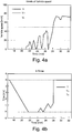
- Fig. 4a depicts schematically the variation in a vehicle's speed with time
- Fig. 4b depicts schematically how vehicle states change according to the system in Fig. 2 with the speed variation in Fig. 4a .
- the vehicle is put into operating state when the operating state is set to travelling state D, i.e. the vehicle is started, at a time of about 16 minutes.
- the vehicle has thereafter a speed which is zero until about 21 minutes and then increases to nearly 20 km/h at 22 minutes before dropping to about zero, rises again to nearly 20 km/h and then drops again so that at about 24 minutes it goes above the low threshold value V L then goes below the low threshold value V L and down to about zero before rising back above the low threshold value V L and dropping to zero and thereafter, from about 27 minutes, exceeds the low threshold value V L and at about 28 minutes exceeds the high threshold value V H .
- the initiation time Ti is set at 5 minutes, i.e. the timer unit 130 has to decrement for a total of 5 minutes, this being the aggregate of increment time and decrement time, before change of operating state from travelling state D to stationary state S takes place.
- the timer unit 130 decrements, as shown in Fig. 4b , to the decrement threshold value T S of zero, which takes 5 minutes, which is the time for which the vehicle speed V is below the low threshold value V L .
- the timer unit 130 will begin to increment.
- the timer unit 130 will revert to decrementing, and once the low threshold value V L is exceeded the timer unit 130 will again increment.
- the timer unit 130 increments and decrements while the speed V varies above and below said low threshold value V L .
- the speed V at about 28 minutes exceeds the high threshold value V H , which is set at 50 km/h, the operating state shifts from stationary state S to travelling state D without the timer unit 130 having incremented to the increment threshold value T D .
- the initiation time Ti is set at 5 minutes, corresponding in this example to the increment threshold value T D .
- the initiation time Ti may be different from the increment threshold value T D .
- the initiation time is within the range of being larger than or equal to the decrement threshold value T S and smaller than or equal to the increment threshold value T D .
- Fig. 5 is a schematic block diagram of a method for determining an operating state according to an embodiment of the present invention.
- the method for determining operating states of a motor vehicle comprises a first step S51 which determines a speed state of the vehicle.
- the method for determining operating states of a motor vehicle comprises a second step S52 which compares said speed state with a predetermined speed.
- the method for determining operating states of a motor vehicle comprises a third step S53 which determines an operating state on the basis of said comparison.
- the method for determining operating states of a motor vehicle comprises a fourth step S54 which provides information about whether the operating state determined is a stationary state or a travelling state.
Landscapes
- Engineering & Computer Science (AREA)
- Mechanical Engineering (AREA)
- Transportation (AREA)
- Physics & Mathematics (AREA)
- Chemical & Material Sciences (AREA)
- Combustion & Propulsion (AREA)
- Automation & Control Theory (AREA)
- General Physics & Mathematics (AREA)
- Mathematical Physics (AREA)
- General Engineering & Computer Science (AREA)
- Power Engineering (AREA)
- Human Computer Interaction (AREA)
- Control Of Transmission Device (AREA)
- Control Of Driving Devices And Active Controlling Of Vehicle (AREA)
- Electric Propulsion And Braking For Vehicles (AREA)
- Control Of Vehicle Engines Or Engines For Specific Uses (AREA)
- Instrument Panels (AREA)
- Combined Controls Of Internal Combustion Engines (AREA)
- Controls For Constant Speed Travelling (AREA)
Description
- The invention relates to a method for determining operating states of a motor vehicle according to the preamble of
claim 1. The invention relates also to a system for determining operating states of a motor vehicle according to the preamble of claim 9. The invention relates also to a motor vehicle. - It is currently usual to indicate how much further a motor vehicle, particularly a car, can travel before it needs refuelling, known as "distance to empty" (DTE). Such a way of informing the driver is excellent for vehicles which travel on roads at certain speeds which are substantially greater than zero towards a desired destination. DTE is not relevant in the case of vehicles which perform more stationary tasks, e.g. within an industry limited to a certain area, timber dressing or the like. If remaining vehicle availability time is more relevant, the driver will for example know whether the vehicle needs refuelling before the current shift ends.
-
US 7206720B2 is concerned with running time left before refuelling is needed, known as "time to empty" (TTE). - A problem is that certain vehicles have both stationary tasks and also tasks which entail travelling at speeds substantially above zero.
- An object of the present invention is to propose a method for determining operating states of a motor vehicle which makes it easy to provide information about current operating states.
- A further object of the present invention is to propose a system for determining operating states of a motor vehicle which makes it easy to provide information about current operating state.
- These and objects indicated by the description set out below are achieved by a method and a system for determining operating states of a motor vehicle, and by a motor vehicle of the kind indicated in the introduction, which further present the features indicated in the characterising parts of the attached
independent claims 1 and 9. Preferred embodiments of the method and system are defined in the attached dependent claims 2-8 and 10-17. - According to the invention, the object is achieved with a method for determining operating states of a motor vehicle comprising the step of determining a speed state of the vehicle, comprising the steps of comparing said speed state with a predetermined speed, determining on the basis of said comparison an operating state and providing information about whether the operating state determined is a stationary state or a travelling state. This makes it easy to provide information if the vehicle is in an operating state and consequently travelling above a certain speed, or in a stationary state and consequently not travelling above said speed, which makes it easy to choose to provide information about how much time is left before the vehicle needs refuelling in the stationary state and how much further it can travel before it needs refuelling in the operating state.
- According to an embodiment, the method comprises the step of determining an operating state and determining a predetermined steadiness of the specific speed state. This avoids the risk that the vehicle's intention might not be to continue for a certain time in the operating state determined, thereby making it easier to determine the correct operating state.
- According to an embodiment, the method further comprises the step of determining whether said specific speed state is distinguished by a vehicle speed below said predetermined speed with at least a predetermined steadiness. This makes it possible to determine whether the vehicle's intention was to continue in a stationary state, so that the determination of stationary states is avoided where the vehicle's intention was not to continue for a certain time in the stationary state.
- According to an embodiment, the method comprises the step of determining a stationary state if said vehicle speed is below said predetermined speed with at least the predetermined steadiness. This means that stationary states are only determined where the vehicle's intention was to continue in a stationary state for a certain time.
- According to an embodiment, the method further comprises the step of determining whether said specific speed state is distinguished by a vehicle speed which exceeds said predetermined speed with at least a predetermined steadiness. This makes it possible to determine whether the vehicle's intention was to continue in a travelling state, so that the determination of travelling states is avoided where the vehicle's intention was not to continue for a certain time in the travelling state.
- According to an embodiment, the method comprises the step of determining a travelling state if said vehicle speed corresponds to or exceeds said predetermined speed with at least the predetermined steadiness. This means that travelling states are only determined where the vehicle's intention was to continue in travelling state for a certain time.
- According to an embodiment, the method comprises the step of determining a travelling state if said speed state is distinguished by a vehicle speed which exceeds a further predetermined speed greater than said predetermined speed. This makes it possible to change from stationary state to travelling state immediately when the vehicle reaches a certain speed such that its intention is to be in a travelling state.
- According to an embodiment, the method comprises the step of determining times for necessary refuelling during determined stationary states. The driver thus receives relevant information about refuelling, i.e. when the vehicle is in stationary state he/she automatically receives information about how much time is left before refuelling is needed, thereby reducing the risk of running out of fuel.
- According to an embodiment, the method comprises the step of determining how much further the vehicle can travel in a determined travelling state before it needs refuelling. The driver thus receives relevant information about refuelling, i.e. when the vehicle is in travelling state he/she automatically receives information about how much further it can travel before needing to refuel, thereby reducing the risk of running out of fuel.
- According to the invention, the object is achieved with a system for determining operating states of a motor vehicle comprising means for determining a speed state of the vehicle, characterised by means for comparing said speed state with a predetermined speed, means for determining an operating state on the basis of said comparison, and means for providing information about whether the operating state determined is a stationary state or a travelling state. This makes it easy to provide information about whether the vehicle is in an operating state and consequently travelling above a certain speed, or in a stationary state and consequently not travelling above said speed, which makes it easy to choose to provide information about how much time is left before the vehicle needs refuelling in the stationary state and how much further it can travel before it needs refuelling in the of the travelling state.
- According to an embodiment, the system comprises said means for determining an operating state and for determining a predetermined steadiness of the specific speed state. This avoids the risk that the vehicle's intention might not be to continue for a certain time in the operating state determined, thereby making it easier to determine the correct operating state.
- According to an embodiment, the system further comprises means for determining whether said specific speed state is distinguished by a vehicle speed below said predetermined speed with at least a predetermined steadiness. This makes it possible to determine whether the vehicle's intention was to continue in a stationary state, so that the determination of stationary states is avoided where the vehicle's intention was not to continue for a certain time in the stationary state.
- According to an embodiment, the system comprises means for determining a stationary state if said vehicle speed is below said predetermined speed with at least the predetermined steadiness. This means that only stationary states are determined where the vehicle's intention was to continue in a stationary state for a certain time.
- According to an embodiment, the system further comprises means for determining whether said specific speed state is distinguished by a vehicle speed which exceeds said predetermined speed with at least a predetermined steadiness. This makes it possible to determine whether the vehicle's intention was to continue in a travelling state, so that the determination of travelling states is avoided where the vehicle's intention was not to continue for a certain time in the travelling state.
- According to an embodiment, the system comprises means for determining a travelling state if said vehicle speed corresponds to or exceeds said predetermined speed with at least the predetermined steadiness. This means that travelling states are only determined where the vehicle's intention was to continue in travelling states for a certain time.
- According to an embodiment, the system comprises means for determining travelling states if said speed state is distinguished by a vehicle speed which exceeds a further predetermined speed greater than said predetermined speed. This makes it possible to change from stationary state to travelling state immediately when the vehicle reaches a certain speed such that its intention is to be in a travelling state.
- According to an embodiment, the system comprises means for determining times for necessary refuelling during determined stationary states. The driver thus receives relevant information about refuelling, i.e. when the vehicle is in a stationary state he/she automatically receives information about how much time is left before refuelling is needed, thereby reducing the risk of running out of fuel.
- According to an embodiment, the system comprises means for determining how much further the vehicle can travel in a determined travelling state before it needs refuelling. The driver thus receives relevant information about refuelling, i.e. when the vehicle is in travelling state he/she automatically receives information about how much further it can travel before needing to refuel, thereby reducing the risk of running out of fuel.
- The present invention will be better understood by reading the following detailed description together with the attached drawings, in which the same reference notations refer to similar items throughout the many views, in which:
-
Fig. 1 is a schematic side view of a motor vehicle; -
Fig. 2 depicts schematically a system for determining operating states of a motor vehicle according to an embodiment of the present invention; -
Fig. 3 is a schematic block diagram of a method for determining an operating state according to an embodiment of the present invention; -
Fig. 4a depicts schematically the variation of a vehicle's speed with time; -
Fig. 4b depicts schematically how vehicle states change according to the system inFig. 2 and the method inFig. 3 with the speed variation inFig. 4a ; and -
Fig. 5 is a schematic block diagram of a method for determining an operating state according to an embodiment of the present invention. - The term "operating state" means herein a state in which the vehicle is running, i.e. its engine is activated/switched on in a travelling state or a stationary state.
- The term "travelling state" means herein a state in which the vehicle is travelling or is within a certain predetermined time intended to travel at a speed which corresponds to or exceeds a predetermined threshold value.
- The term "stationary state" means herein a state in which the vehicle is stationary or travelling at a certain speed below said predetermined threshold value.
-
Figure 1 depicts a side view of avehicle 1. The exemplifiedvehicle 1 is a heavy vehicle in the form of a truck, e.g. a commercial vehicle. The vehicle may alternatively be a bus or a car. The vehicle is provided with a system for determining operating states of a motor vehicle according to the present invention.Fig. 2 is a schematic block diagram of asystem 2 for determining an operating state according to an embodiment of the present invention. - The
system 2 comprises anelectronic control unit 100 for controlling the vehicle's systems. Theelectronic control unit 100 is signal-connected via alink 111 to a vehicle activation means 110 for activating the vehicle so that it changes from a non-operating state to an operating state, i.e. its engine is started or at least the ignition is switched on. Theelectronic control unit 100 is arranged to receive from said vehicle activation means 110 via the link a signal which represents vehicle activation data. - The
electronic control unit 100 is arranged to compare said vehicle activation data with a predetermined vehicle activation value which represents the vehicle being activated, i.e. the engine changing from being switched off to running. - According to an embodiment of the present invention, when said vehicle activation value is fulfilled, i.e. where the vehicle's engine changes from being switched off to running the
electronic control unit 100 is arranged to, to activate a travelling state D so that thesystem 2 at the time of starting the vehicle is put into said travelling state D, i.e. thesystem 2 assumes that the vehicle is regarded as being as soon as possible run at a certain speed which corresponds to or is higher than a low threshold value VL, i.e. the vehicle is not regarded as being in a stationary state S. - According to an alternative embodiment of the present invention, when said vehicle activation value is fulfilled, i.e. where the vehicle's engine changes from being switched off to running, the
electronic control unit 100 is arranged to activate a stationary state S so that thesystem 2 at the time of starting the vehicle is put into said stationary state S, i.e. the system assumes that the vehicle is regarded as being in a stationary state S and is consequently travelling at a speed below said low threshold value VL. - The
electronic control unit 100 is signal-connected via alink 121 to a speed detection means 120 which is adapted to monitoring the vehicle speed. Theelectronic control unit 100 is arranged to receive from the speed detection means 120 via a link a signal which represents vehicle speed data. - The
electronic control unit 100 is signal-connected via afirst link 131 and asecond link 132 to atimer unit 130 which is adapted to incrementing or decrementing. Theelectronic control unit 100 is arranged to send to thetimer unit 130 via the first link 131 a signal which represents activation data for activating thetimer unit 130 to increment or decrement. Theelectronic control unit 100 is arranged to receive from thetimer unit 130 via the second link 132 a signal which represents timer data. According to a variant, thetimer unit 130 is an integral part of theelectronic control unit 100. - The
electronic control unit 100 is arranged to compare said vehicle speed data with predetermined vehicle speed threshold values VL, VH. Said threshold values comprise a low threshold value VL and a high threshold value VH which is higher than the low threshold value VL. - The
electronic control unit 100 is signal-connected via alink 141 to anoperating state unit 140 for activation of the latter for provision of information about operating states. According to this embodiment, the operatingstate unit 140 is arranged to provide information about time left before refuelling is needed (TTE) or how much further the vehicle can travel before needing refuelling (DTE). - According to an embodiment of the present invention, when said vehicle activation value is fulfilled and a travelling state D is activated, the
electronic control unit 100 is arranged to set a decrement initiation time Ti which represents how long thetimer unit 130 has to decrement before a predetermined decrement threshold value TS is fulfilled. - During decrementing from said decrement initiation time Ti, the
electronic control unit 100 is arranged to compare timer data with said decrement threshold value TS. When said decrement threshold value TS is reached, theelectronic control unit 100 is arranged to send to theoperating state unit 140 via a link a signal which represents data for stationary state, whereupon the operatingstate unit 140 is arranged to change the state from travelling state D to stationary state S, and to provide information about time left before needing to refuel (TTE). - According to an embodiment of the present invention, when said vehicle activation value is fulfilled and a stationary state S is activated, the
electronic control unit 100 is arranged to set an initiation time which represents how long thetimer unit 130 has to increment before a predetermined increment threshold value TD is fulfilled. - During incrementing from said increment initiation time, the
electronic control unit 100 is arranged to compare timer data with said increment threshold value TD. When said increment threshold value TD is reached, theelectronic control unit 100 is arranged to send to theoperating state unit 140 via a link a signal which represents travelling state data, whereupon the operatingstate unit 140 is arranged to change the state from stationary state to travelling state D, and to provide information about how much further the vehicle can travel before needing to refuel (DTE). - In operating states of the vehicle where said vehicle speed data are below said low threshold value VL, the
electronic control unit 100 is arranged to send to thetimer unit 130 via said first link signals to activate decrementing so that thetimer unit 130 begins to decrement.. - When the
timer unit 130 is activated to decrement, theelectronic control unit 100 is arranged to receive via thelink 131 signals which represent decrement timer data. Theelectronic control unit 100 is arranged to compare said decrement timer data with said predetermined decrement threshold value TS. - When said decrement timer data amount to at least said decrement threshold value TS, the
electronic control unit 100 is arranged to send to the operating state unit 140 a signal to change operating state to stationary state S. - In operating states of the vehicle where said vehicle speed data are equal to or exceed said low threshold value VL, the
electronic control unit 100 is arranged to send to thetimer unit 130 via saidfirst link 131 signals to activate incrementing so that thetimer unit 130 begins to increment. - When the
timer unit 130 is activated to increment, theelectronic control unit 100 is arranged to receive via thelink 131 signals which represent increment timer data. Theelectronic control unit 100 is arranged to compare said increment timer data with said predetermined increment threshold value TD. - When said increment timer data amount to at least said increment threshold value TD, the
electronic control unit 100 is arranged to send a signal to theoperating state unit 140 to change operating state to travelling state D. - The
electronic control unit 100 is arranged to compare said vehicle speed data with said predetermined vehicle speed high threshold value VH. If said vehicle speed data exceed said high threshold value VH, theelectronic control unit 100 is arranged to send to theoperating state unit 140 via the link 141 a signal to change immediately to travelling state without taking timer data into account, i.e. without catering for time for incrementing of thetimer unit 130. - According to an embodiment, the
electronic control unit 100 is signal-connected via alink 151 to aparking brake unit 150. Theelectronic control unit 100 is arranged to receive from said parking brake unit 150 a signal which represents parking brake data about whether theparking brake unit 150 is activated. Theelectronic control unit 100 is adapted to comparing said parking brake data with a predetermined parking brake activation value. When said parking brake activation value is fulfilled, i.e. when theparking brake unit 150 is activated, theelectronic control unit 100 is arranged to send to the operating state unit 140 a signal to change the operating state to stationary state without catering for time for decrementing of the timer unit. - According to an embodiment, the
electronic control unit 100 is signal-connected via alink 161 to avehicle transmission unit 160. Theelectronic control unit 100 is arranged to receive from said vehicle transmission unit 160 a signal which represents transmission state data about whether saidtransmission unit 160 is in neutral position/parking position. Theelectronic control unit 100 is arranged to compare said transmission state data with a predetermined transmission state value. When said transmission state value is fulfilled, i.e. when thevehicle transmission unit 160 is activated, theelectronic control unit 100 is arranged to send to the operating state unit 140 a signal to change the operating state to stationary state. -
Fig. 3 is a schematic block diagram of a method for determining operating states of a motor vehicle according to an embodiment of the present invention. Determination of operating states involves providing information about whether determined operating states are a stationary state S, in which case a time to needing to refuel (TTE) is determined, or a travelling state D, in which case a distance to needing to refuel (DTE) is determined. The primary state is regarded as being travelling state D, which is initiated when starting the vehicle so that information about DTE is determined. - The method comprises the step S31 of setting the time T of a
timer unit 130 according toFig. 2 to an initiation time Ti which determines the initial time for a vehicle to pass the low threshold value VL before switching to stationary state S. - A step S32 of the method investigates whether the vehicle is in operation. If it is not, the method is reset.
- If the vehicle is in operation, a method step S33 investigates whether its speed V is lower than the low threshold value VL. If it is, then the
timer unit 130 will decrement. - A method step S34 then investigates whether said decrement threshold value TS is fulfilled, i.e. whether the decrement time T of the
timer unit 130 is equal to or lower than said decrement threshold value TS. If it is, then a method step S35 will set the decrement time T to the decrement threshold value TS, whereupon a method step S36 changes the operating state to stationary state S so that information about TTE is provided. - If the decrement threshold value TS is not fulfilled, this calls for investigation as to whether the vehicle is running, and if it is, then method step S33 investigates whether the speed V is lower than the low threshold value VL.
- If the vehicle speed V is higher than or equal to the low threshold value VL, a method step S37 investigates whether it is higher than the high threshold value VH. If it is, then the increment time of the
timer unit 130 will be set to the increment threshold value TD, whereupon the stationary state changes to travelling state D so that information about DTE is provided. Thereupon the operating state changes to travelling state D irrespective of whether said increment time T fulfils the increment threshold value TD, i.e. the operating state is set to travelling state as soon as the vehicle speed V exceeds said high threshold value VH. - If the vehicle speed V is higher than or equal to the low threshold value VL but does not exceed the high threshold value VH, the
timer unit 130 will increment. A method step S38 then investigates whether said increment threshold value TD is fulfilled, i.e. whether the increment time T of thetimer unit 130 is equal to or lower than said increment threshold value TD. If it is, then a method step S39 will set the increment time T to the increment threshold value TD, whereupon a method step S40 changes the operating state to travelling state D so that information about DTE is provided. - Consequently, if the operating state is travelling state D and the vehicle speed V is below the low threshold value VL so that the
timer unit 130 decrements and the vehicle speed V then increases and becomes higher than the low threshold value VL before thetimer unit 130 has decremented to the decrement threshold value TS, thetimer unit 130 will instead begin to increment, thereby maintaining the travelling state D. - Similarly, if the operating state is stationary state S and the vehicle speed V is higher than or equal to the low threshold value VL so that the
timer unit 130 increments and the vehicle speed V then decreases to below the low threshold value VL before thetimer unit 130 has incremented to the increment threshold value TD, thetimer unit 130 will instead begin to decrement, thereby maintaining the stationary state S. - In the case of a vehicle which operates both in stationary state S and in travelling state D, the driver will, without needing to take any action him/herself, receive correct information about refuelling, i.e. the relevant information at a given time. The driver will be informed about TTE when operating in stationary state S, and about DTE when operating in travelling state D in which the vehicle travels at a speed exceeding said low threshold value VL.
- Switching between stationary state S and travelling state D is also based not only on vehicle speed V but also on steadiness T of vehicle speed, i.e. vehicle speed being above or below the low threshold value VL for a certain time, i.e. the time during which the
timer unit 130 increments or decrements. This means that the driver will not be disturbed unnecessarily by unnecessary switches between stationary state S and travelling state D, e.g. when the operating state shifts from travelling state D to stationary state S at red traffic lights. Vehicles with stationary tasks may also move at medium-high speeds for a certain time without departing from stationary state S. - The vehicle will also assume travelling state D as soon as its speed V exceeds said high threshold value VH, so that it does not continue in stationary state S at times when it is obvious that the intention is to be in travelling state D.
- The separate initiation time Ti may be adjusted so that travelling state D is maintained for a desired length of time initially even if the vehicle is idling.
-
Fig. 4a depicts schematically the variation in a vehicle's speed with time, andFig. 4b depicts schematically how vehicle states change according to the system inFig. 2 with the speed variation inFig. 4a . - Thus the vehicle is put into operating state when the operating state is set to travelling state D, i.e. the vehicle is started, at a time of about 16 minutes. The vehicle has thereafter a speed which is zero until about 21 minutes and then increases to nearly 20 km/h at 22 minutes before dropping to about zero, rises again to nearly 20 km/h and then drops again so that at about 24 minutes it goes above the low threshold value VL then goes below the low threshold value VL and down to about zero before rising back above the low threshold value VL and dropping to zero and thereafter, from about 27 minutes, exceeds the low threshold value VL and at about 28 minutes exceeds the high threshold value VH.
- As may be seen in
Fig. 4b , the initiation time Ti is set at 5 minutes, i.e. thetimer unit 130 has to decrement for a total of 5 minutes, this being the aggregate of increment time and decrement time, before change of operating state from travelling state D to stationary state S takes place. In the case according toFigs. 4a, and 4b , thetimer unit 130 decrements, as shown inFig. 4b , to the decrement threshold value TS of zero, which takes 5 minutes, which is the time for which the vehicle speed V is below the low threshold value VL. When for the first time the speed V corresponds to or exceeds the low threshold value VL at about 24 minutes, thetimer unit 130 will begin to increment. Once the speed V is below the low threshold value VL, thetimer unit 130 will revert to decrementing, and once the low threshold value VL is exceeded thetimer unit 130 will again increment. Thetimer unit 130 increments and decrements while the speed V varies above and below said low threshold value VL. When the speed V at about 28 minutes exceeds the high threshold value VH, which is set at 50 km/h, the operating state shifts from stationary state S to travelling state D without thetimer unit 130 having incremented to the increment threshold value TD. - Here the initiation time Ti is set at 5 minutes, corresponding in this example to the increment threshold value TD. According to an alternative variant, the initiation time Ti may be different from the increment threshold value TD. The initiation time is within the range of being larger than or equal to the decrement threshold value TS and smaller than or equal to the increment threshold value TD.
-
Fig. 5 is a schematic block diagram of a method for determining an operating state according to an embodiment of the present invention. - According to an embodiment, the method for determining operating states of a motor vehicle comprises a first step S51 which determines a speed state of the vehicle.
- According to an embodiment, the method for determining operating states of a motor vehicle comprises a second step S52 which compares said speed state with a predetermined speed.
- According to an embodiment, the method for determining operating states of a motor vehicle comprises a third step S53 which determines an operating state on the basis of said comparison.
- According to an embodiment, the method for determining operating states of a motor vehicle comprises a fourth step S54 which provides information about whether the operating state determined is a stationary state or a travelling state.
- The above description of the preferred embodiments of the present invention is provided for illustrative and descriptive purposes. It is not intended to be exhaustive or to restrict the invention to the variants described. Many modifications and variations will obviously suggest themselves to specialists. The embodiments were chosen and described in order best to explain the principles of the invention and practical applications thereof and thereby enable one skilled in the art to understand the invention for different embodiments and with the various modifications applicable to the intended use.
Claims (11)
- A method for determining operating states (D, S) of a motor vehicle (1) comprising the step of determining a speed state (V) of the vehicle, comprising the steps of- comparing (S33, S52, S37) said speed state (V) with a predetermined vehicle speed (VL, VH),- determining (S36, S40, S34, S38, S53) an operating state (D, S) on the basis of said comparison, and- providing information about whether the operating state determined is a stationary state (S) or a travelling state (D),characterised in that- the step of determining an operating state comprises determining (S34, S38) a predetermined duration of the specific speed state, and, further comprising the step of determining (S33) whether said specific speed state (V) is distinguished by a vehicle speed which is below said predetermined speed (VL) with at least a predetermined duration (TS), wherein said method is comprising the step of:- determining times to necessary refuelling (TTE) pertaining to stationary states (S) determined, or- determining distances to necessary refuelling (DTE) pertaining to travelling states (D) determined.
- A method according to claim 1, comprising the step of determining (S36) a stationary state (S) if said vehicle speed is below said predetermined speed (VL) with at least the predetermined duration (TS).
- A method according to claim 1, further comprising the step of determining (S33) whether said specific speed state (V) is distinguished by a vehicle speed which exceeds said predetermined speed (VL) with at least a predetermined duration (TD).
- A method according to claim 3, comprising the step of determining (S40) a travelling state (D) if said vehicle speed corresponds to or exceeds said predetermined speed (VL) with at least the predetermined duration (TD).
- A method according to any one of the foregoing claims, comprising the step of determining (S40) a travelling state if said speed state (V) is distinguished by a vehicle speed which exceeds a further predetermined speed (VH) greater than said predetermined speed (VL).
- A system for determining operating states (D, S) of a motor vehicle (1) comprising means (120) for determining a speed state (V) of the vehicle, comprising means (100) for comparing said speed state (V) with a predetermined speed, means (100, 130) for determining an operating state (D, S) on the basis of said comparison, and means (140) for providing information about whether an operating state determined is a stationary state (S) or a travelling state (D), characterised in that said means (100, 130) for determining an operating state comprise means (130) for determining a predetermined duration of the specific speed state (D, S), and comprising means (100) for determining whether said specific speed state (V) is distinguished by a vehicle speed which is below said predetermined speed (VL) with at least a predetermined duration (TS), wherein said system is comprising means for:- determining times to necessary refuelling (TTE) pertaining to the stationary state (S) determined, or- determining distances to necessary refuelling (DTE) pertaining to the travelling state (D) determined.
- A system according to claim 6, comprising means (100) for determining a stationary state (S) if said vehicle speed is below said predetermined speed (VL) with at least the predetermined duration (TS).
- A system according to claim 6, further comprising means (100) for determining whether said specific speed state (V) is distinguished by a vehicle speed which exceeds said predetermined speed (VL) with at least a predetermined duration (TS).
- A system according to claim 8, comprising means (100, 140) for determining a travelling state (D) if said vehicle speed corresponds to or exceeds said predetermined speed (VL) with at least the predetermined duration (TD).
- A system according to any one of claims 6-9, comprising means (100) for determining travelling state (D) if said speed state (V) is distinguished by a vehicle speed which exceeds a further predetermined speed (VH) greater than said predetermined speed (VL).
- A motor vehicle comprising a system according to any one of claims 6-10.
Applications Claiming Priority (2)
| Application Number | Priority Date | Filing Date | Title |
|---|---|---|---|
| SE1051052A SE535210C2 (en) | 2010-10-07 | 2010-10-07 | Method and system for determining the operating condition of a motor vehicle |
| PCT/SE2011/051187 WO2012047166A1 (en) | 2010-10-07 | 2011-10-04 | Method and system for determining operating states of a motor vehicle |
Publications (3)
| Publication Number | Publication Date |
|---|---|
| EP2625057A1 EP2625057A1 (en) | 2013-08-14 |
| EP2625057A4 EP2625057A4 (en) | 2014-05-07 |
| EP2625057B1 true EP2625057B1 (en) | 2016-05-04 |
Family
ID=45927972
Family Applications (1)
| Application Number | Title | Priority Date | Filing Date |
|---|---|---|---|
| EP11831009.3A Active EP2625057B1 (en) | 2010-10-07 | 2011-10-04 | Method and system for determining operating states of a motor vehicle |
Country Status (8)
| Country | Link |
|---|---|
| EP (1) | EP2625057B1 (en) |
| JP (1) | JP5690408B2 (en) |
| KR (1) | KR101918216B1 (en) |
| CN (1) | CN103153679A (en) |
| BR (1) | BR112013005395B1 (en) |
| RU (1) | RU2536756C1 (en) |
| SE (1) | SE535210C2 (en) |
| WO (1) | WO2012047166A1 (en) |
Cited By (1)
| Publication number | Priority date | Publication date | Assignee | Title |
|---|---|---|---|---|
| WO2019052745A1 (en) * | 2017-09-12 | 2019-03-21 | Robert Bosch Gmbh | METHOD FOR DETERMINING A DEACTIVATED OPERATING STATUS OF A MOTOR VEHICLE |
Families Citing this family (2)
| Publication number | Priority date | Publication date | Assignee | Title |
|---|---|---|---|---|
| SE535210C2 (en) * | 2010-10-07 | 2012-05-22 | Scania Cv Ab | Method and system for determining the operating condition of a motor vehicle |
| KR101406504B1 (en) * | 2013-05-15 | 2014-06-13 | 기아자동차주식회사 | Method and system for diagnosing lack of coolant |
Citations (1)
| Publication number | Priority date | Publication date | Assignee | Title |
|---|---|---|---|---|
| WO1995010026A1 (en) * | 1993-10-04 | 1995-04-13 | Seiko Epson Corporation | Image data operating device for vehicle |
Family Cites Families (14)
| Publication number | Priority date | Publication date | Assignee | Title |
|---|---|---|---|---|
| JP2536886Y2 (en) * | 1991-10-28 | 1997-05-28 | 矢崎総業株式会社 | Tachograph |
| JPH09297034A (en) * | 1996-05-07 | 1997-11-18 | Fujitsu Ten Ltd | Navigation apparatus |
| US6667726B1 (en) * | 1999-01-19 | 2003-12-23 | C.R.F. Societa Consortile Per Azioni | Vehicle display device |
| JP3747015B2 (en) * | 2002-07-11 | 2006-02-22 | 本田技研工業株式会社 | Fuel consumption meter for vehicles |
| CN2566228Y (en) * | 2002-08-21 | 2003-08-13 | 邯郸市科昊电器有限公司 | Motor vehicle running state monitoring recording system |
| CN1802273B (en) * | 2003-06-06 | 2010-05-12 | 沃尔沃技术公司 | Method and apparatus for controlling vehicle subsystems based on interpreted driver activity |
| CN1267297C (en) * | 2003-08-15 | 2006-08-02 | 南京金陵紫光系统工程有限公司 | Assembled instrument step motor controller of vehicle and control mode thereof |
| DE10346511B4 (en) * | 2003-10-02 | 2008-01-31 | Daimler Ag | Device for improving the visibility in a motor vehicle |
| KR20070102588A (en) * | 2005-01-31 | 2007-10-18 | 히타치 긴조쿠 가부시키가이샤 | Drop detection method and drop detection device |
| US7206720B2 (en) * | 2005-02-24 | 2007-04-17 | Lapant Todd | Computer-controlled auxiliary fuel tank system with multi-function monitoring system and user calibration capabilities |
| JP2007094703A (en) * | 2005-09-28 | 2007-04-12 | Toyota Motor Corp | Vehicle information provision system |
| JP4752661B2 (en) * | 2006-08-01 | 2011-08-17 | 株式会社デンソー | Transmitter and tire pressure detecting device having the same |
| JP4958543B2 (en) * | 2006-12-28 | 2012-06-20 | 日立建機株式会社 | Display device for wheel type work machine |
| SE535210C2 (en) * | 2010-10-07 | 2012-05-22 | Scania Cv Ab | Method and system for determining the operating condition of a motor vehicle |
-
2010
- 2010-10-07 SE SE1051052A patent/SE535210C2/en unknown
-
2011
- 2011-10-04 KR KR1020137011459A patent/KR101918216B1/en active Active
- 2011-10-04 WO PCT/SE2011/051187 patent/WO2012047166A1/en not_active Ceased
- 2011-10-04 EP EP11831009.3A patent/EP2625057B1/en active Active
- 2011-10-04 CN CN2011800484358A patent/CN103153679A/en active Pending
- 2011-10-04 RU RU2013120522/11A patent/RU2536756C1/en active
- 2011-10-04 JP JP2013532750A patent/JP5690408B2/en not_active Expired - Fee Related
- 2011-10-04 BR BR112013005395-0A patent/BR112013005395B1/en active IP Right Grant
Patent Citations (1)
| Publication number | Priority date | Publication date | Assignee | Title |
|---|---|---|---|---|
| WO1995010026A1 (en) * | 1993-10-04 | 1995-04-13 | Seiko Epson Corporation | Image data operating device for vehicle |
Cited By (2)
| Publication number | Priority date | Publication date | Assignee | Title |
|---|---|---|---|---|
| WO2019052745A1 (en) * | 2017-09-12 | 2019-03-21 | Robert Bosch Gmbh | METHOD FOR DETERMINING A DEACTIVATED OPERATING STATUS OF A MOTOR VEHICLE |
| CN111051144A (en) * | 2017-09-12 | 2020-04-21 | 罗伯特·博世有限公司 | Method for determining a deactivated operating state of a motor vehicle |
Also Published As
| Publication number | Publication date |
|---|---|
| KR20130139974A (en) | 2013-12-23 |
| KR101918216B1 (en) | 2018-11-13 |
| RU2536756C1 (en) | 2014-12-27 |
| CN103153679A (en) | 2013-06-12 |
| JP2013545006A (en) | 2013-12-19 |
| EP2625057A4 (en) | 2014-05-07 |
| SE535210C2 (en) | 2012-05-22 |
| JP5690408B2 (en) | 2015-03-25 |
| SE1051052A1 (en) | 2012-04-08 |
| BR112013005395A2 (en) | 2016-06-07 |
| EP2625057A1 (en) | 2013-08-14 |
| BR112013005395B1 (en) | 2021-02-23 |
| WO2012047166A1 (en) | 2012-04-12 |
| RU2013120522A (en) | 2014-11-20 |
Similar Documents
| Publication | Publication Date | Title |
|---|---|---|
| US8784267B2 (en) | Method for controlling a rolling or coasting function of a vehicle | |
| US8521379B2 (en) | Method for operating a vehicle having a freewheel mode or a rolling mode | |
| CN102077147B (en) | Speed control system for vehicles | |
| EP2800670B1 (en) | Method and system for controlling a driving distance | |
| US8095286B2 (en) | Method for controlling shifts in an automated gearshift transmission | |
| US10710586B2 (en) | Systems and methods for idle coasting management | |
| EP4163175B1 (en) | Method and apparatus for controlling cruise control | |
| JP2012067918A (en) | Method for controlling automatic transmission for motor vehicle | |
| US20190168755A1 (en) | Driver Assistance System in a Motor Vehicle | |
| EP2931582B1 (en) | Method and system for guidance of driver behaviour during driving of vehicles | |
| CA2831499A1 (en) | Flexible maximum vehicle speed method | |
| US20100299042A1 (en) | Method and system for encouraging vehicle operator compliance | |
| EP2625057A1 (en) | Method and system for determining operating states of a motor vehicle | |
| CN101596890A (en) | A kind of automatic braking control system for preventing automobile from crashing during reversing | |
| EP3052837B1 (en) | Method and arrangement for adapting the starting gear of a vehicle | |
| WO2000063592A1 (en) | Method and apparatus for controlling an automatic gearbox | |
| US20060276950A1 (en) | Motor vehicle | |
| EP2931580B1 (en) | Method and system for controlling the driving of a vehicle | |
| KR20080007246A (en) | How to control the driving function of the vehicle | |
| WO2009156318A1 (en) | Method for engine control | |
| SE1550123A1 (en) | Method and system for controlling a clutch of a vehicle | |
| US6553815B1 (en) | Method and apparatus for permitting stable operation of a vehicle at an extremely low vehicle speed | |
| CN118405129A (en) | Vehicle follow-up start control method, device, equipment and storage medium | |
| KR20180102271A (en) | Method for controlling smart power of vehicle | |
| WO2014098732A1 (en) | Method and system for guidance of driver behaviour during driving of motor vehicles |
Legal Events
| Date | Code | Title | Description |
|---|---|---|---|
| PUAI | Public reference made under article 153(3) epc to a published international application that has entered the european phase |
Free format text: ORIGINAL CODE: 0009012 |
|
| 17P | Request for examination filed |
Effective date: 20130507 |
|
| AK | Designated contracting states |
Kind code of ref document: A1 Designated state(s): AL AT BE BG CH CY CZ DE DK EE ES FI FR GB GR HR HU IE IS IT LI LT LU LV MC MK MT NL NO PL PT RO RS SE SI SK SM TR |
|
| RIN1 | Information on inventor provided before grant (corrected) |
Inventor name: JERHAMMAR, ANDREAS Inventor name: ERIKSSON, NILS Inventor name: WALLEBAECK, PETER |
|
| DAX | Request for extension of the european patent (deleted) | ||
| A4 | Supplementary search report drawn up and despatched |
Effective date: 20140403 |
|
| RIC1 | Information provided on ipc code assigned before grant |
Ipc: G01P 13/00 20060101ALI20140328BHEP Ipc: B60K 35/00 20060101AFI20140328BHEP |
|
| 17Q | First examination report despatched |
Effective date: 20150121 |
|
| GRAP | Despatch of communication of intention to grant a patent |
Free format text: ORIGINAL CODE: EPIDOSNIGR1 |
|
| RIN1 | Information on inventor provided before grant (corrected) |
Inventor name: WALLEBAECK, PETER Inventor name: ERIKSSON, NILS Inventor name: JERHAMMAR, ANDREAS |
|
| INTG | Intention to grant announced |
Effective date: 20151221 |
|
| GRAS | Grant fee paid |
Free format text: ORIGINAL CODE: EPIDOSNIGR3 |
|
| GRAA | (expected) grant |
Free format text: ORIGINAL CODE: 0009210 |
|
| AK | Designated contracting states |
Kind code of ref document: B1 Designated state(s): AL AT BE BG CH CY CZ DE DK EE ES FI FR GB GR HR HU IE IS IT LI LT LU LV MC MK MT NL NO PL PT RO RS SE SI SK SM TR |
|
| REG | Reference to a national code |
Ref country code: GB Ref legal event code: FG4D |
|
| REG | Reference to a national code |
Ref country code: CH Ref legal event code: EP |
|
| REG | Reference to a national code |
Ref country code: AT Ref legal event code: REF Ref document number: 796586 Country of ref document: AT Kind code of ref document: T Effective date: 20160515 |
|
| REG | Reference to a national code |
Ref country code: IE Ref legal event code: FG4D |
|
| REG | Reference to a national code |
Ref country code: DE Ref legal event code: R096 Ref document number: 602011026257 Country of ref document: DE |
|
| REG | Reference to a national code |
Ref country code: NL Ref legal event code: MP Effective date: 20160504 |
|
| REG | Reference to a national code |
Ref country code: LT Ref legal event code: MG4D |
|
| REG | Reference to a national code |
Ref country code: FR Ref legal event code: PLFP Year of fee payment: 6 |
|
| PG25 | Lapsed in a contracting state [announced via postgrant information from national office to epo] |
Ref country code: NO Free format text: LAPSE BECAUSE OF FAILURE TO SUBMIT A TRANSLATION OF THE DESCRIPTION OR TO PAY THE FEE WITHIN THE PRESCRIBED TIME-LIMIT Effective date: 20160804 Ref country code: NL Free format text: LAPSE BECAUSE OF FAILURE TO SUBMIT A TRANSLATION OF THE DESCRIPTION OR TO PAY THE FEE WITHIN THE PRESCRIBED TIME-LIMIT Effective date: 20160504 Ref country code: LT Free format text: LAPSE BECAUSE OF FAILURE TO SUBMIT A TRANSLATION OF THE DESCRIPTION OR TO PAY THE FEE WITHIN THE PRESCRIBED TIME-LIMIT Effective date: 20160504 Ref country code: FI Free format text: LAPSE BECAUSE OF FAILURE TO SUBMIT A TRANSLATION OF THE DESCRIPTION OR TO PAY THE FEE WITHIN THE PRESCRIBED TIME-LIMIT Effective date: 20160504 |
|
| REG | Reference to a national code |
Ref country code: AT Ref legal event code: MK05 Ref document number: 796586 Country of ref document: AT Kind code of ref document: T Effective date: 20160504 |
|
| PG25 | Lapsed in a contracting state [announced via postgrant information from national office to epo] |
Ref country code: GR Free format text: LAPSE BECAUSE OF FAILURE TO SUBMIT A TRANSLATION OF THE DESCRIPTION OR TO PAY THE FEE WITHIN THE PRESCRIBED TIME-LIMIT Effective date: 20160805 Ref country code: HR Free format text: LAPSE BECAUSE OF FAILURE TO SUBMIT A TRANSLATION OF THE DESCRIPTION OR TO PAY THE FEE WITHIN THE PRESCRIBED TIME-LIMIT Effective date: 20160504 Ref country code: SE Free format text: LAPSE BECAUSE OF FAILURE TO SUBMIT A TRANSLATION OF THE DESCRIPTION OR TO PAY THE FEE WITHIN THE PRESCRIBED TIME-LIMIT Effective date: 20160504 Ref country code: RS Free format text: LAPSE BECAUSE OF FAILURE TO SUBMIT A TRANSLATION OF THE DESCRIPTION OR TO PAY THE FEE WITHIN THE PRESCRIBED TIME-LIMIT Effective date: 20160504 Ref country code: LV Free format text: LAPSE BECAUSE OF FAILURE TO SUBMIT A TRANSLATION OF THE DESCRIPTION OR TO PAY THE FEE WITHIN THE PRESCRIBED TIME-LIMIT Effective date: 20160504 Ref country code: ES Free format text: LAPSE BECAUSE OF FAILURE TO SUBMIT A TRANSLATION OF THE DESCRIPTION OR TO PAY THE FEE WITHIN THE PRESCRIBED TIME-LIMIT Effective date: 20160504 Ref country code: PT Free format text: LAPSE BECAUSE OF FAILURE TO SUBMIT A TRANSLATION OF THE DESCRIPTION OR TO PAY THE FEE WITHIN THE PRESCRIBED TIME-LIMIT Effective date: 20160905 |
|
| PG25 | Lapsed in a contracting state [announced via postgrant information from national office to epo] |
Ref country code: DK Free format text: LAPSE BECAUSE OF FAILURE TO SUBMIT A TRANSLATION OF THE DESCRIPTION OR TO PAY THE FEE WITHIN THE PRESCRIBED TIME-LIMIT Effective date: 20160504 Ref country code: RO Free format text: LAPSE BECAUSE OF FAILURE TO SUBMIT A TRANSLATION OF THE DESCRIPTION OR TO PAY THE FEE WITHIN THE PRESCRIBED TIME-LIMIT Effective date: 20160504 Ref country code: SK Free format text: LAPSE BECAUSE OF FAILURE TO SUBMIT A TRANSLATION OF THE DESCRIPTION OR TO PAY THE FEE WITHIN THE PRESCRIBED TIME-LIMIT Effective date: 20160504 Ref country code: EE Free format text: LAPSE BECAUSE OF FAILURE TO SUBMIT A TRANSLATION OF THE DESCRIPTION OR TO PAY THE FEE WITHIN THE PRESCRIBED TIME-LIMIT Effective date: 20160504 Ref country code: CZ Free format text: LAPSE BECAUSE OF FAILURE TO SUBMIT A TRANSLATION OF THE DESCRIPTION OR TO PAY THE FEE WITHIN THE PRESCRIBED TIME-LIMIT Effective date: 20160504 |
|
| REG | Reference to a national code |
Ref country code: DE Ref legal event code: R097 Ref document number: 602011026257 Country of ref document: DE |
|
| PG25 | Lapsed in a contracting state [announced via postgrant information from national office to epo] |
Ref country code: AT Free format text: LAPSE BECAUSE OF FAILURE TO SUBMIT A TRANSLATION OF THE DESCRIPTION OR TO PAY THE FEE WITHIN THE PRESCRIBED TIME-LIMIT Effective date: 20160504 Ref country code: PL Free format text: LAPSE BECAUSE OF FAILURE TO SUBMIT A TRANSLATION OF THE DESCRIPTION OR TO PAY THE FEE WITHIN THE PRESCRIBED TIME-LIMIT Effective date: 20160504 Ref country code: BE Free format text: LAPSE BECAUSE OF FAILURE TO SUBMIT A TRANSLATION OF THE DESCRIPTION OR TO PAY THE FEE WITHIN THE PRESCRIBED TIME-LIMIT Effective date: 20160504 Ref country code: SM Free format text: LAPSE BECAUSE OF FAILURE TO SUBMIT A TRANSLATION OF THE DESCRIPTION OR TO PAY THE FEE WITHIN THE PRESCRIBED TIME-LIMIT Effective date: 20160504 |
|
| PLBE | No opposition filed within time limit |
Free format text: ORIGINAL CODE: 0009261 |
|
| STAA | Information on the status of an ep patent application or granted ep patent |
Free format text: STATUS: NO OPPOSITION FILED WITHIN TIME LIMIT |
|
| 26N | No opposition filed |
Effective date: 20170207 |
|
| PG25 | Lapsed in a contracting state [announced via postgrant information from national office to epo] |
Ref country code: SI Free format text: LAPSE BECAUSE OF FAILURE TO SUBMIT A TRANSLATION OF THE DESCRIPTION OR TO PAY THE FEE WITHIN THE PRESCRIBED TIME-LIMIT Effective date: 20160504 |
|
| REG | Reference to a national code |
Ref country code: CH Ref legal event code: PL |
|
| PG25 | Lapsed in a contracting state [announced via postgrant information from national office to epo] |
Ref country code: MC Free format text: LAPSE BECAUSE OF FAILURE TO SUBMIT A TRANSLATION OF THE DESCRIPTION OR TO PAY THE FEE WITHIN THE PRESCRIBED TIME-LIMIT Effective date: 20160504 |
|
| REG | Reference to a national code |
Ref country code: IE Ref legal event code: MM4A |
|
| PG25 | Lapsed in a contracting state [announced via postgrant information from national office to epo] |
Ref country code: LI Free format text: LAPSE BECAUSE OF NON-PAYMENT OF DUE FEES Effective date: 20161031 Ref country code: CH Free format text: LAPSE BECAUSE OF NON-PAYMENT OF DUE FEES Effective date: 20161031 |
|
| PG25 | Lapsed in a contracting state [announced via postgrant information from national office to epo] |
Ref country code: LU Free format text: LAPSE BECAUSE OF NON-PAYMENT OF DUE FEES Effective date: 20161004 |
|
| REG | Reference to a national code |
Ref country code: FR Ref legal event code: PLFP Year of fee payment: 7 |
|
| PG25 | Lapsed in a contracting state [announced via postgrant information from national office to epo] |
Ref country code: IE Free format text: LAPSE BECAUSE OF NON-PAYMENT OF DUE FEES Effective date: 20161004 |
|
| PG25 | Lapsed in a contracting state [announced via postgrant information from national office to epo] |
Ref country code: CY Free format text: LAPSE BECAUSE OF FAILURE TO SUBMIT A TRANSLATION OF THE DESCRIPTION OR TO PAY THE FEE WITHIN THE PRESCRIBED TIME-LIMIT Effective date: 20160504 Ref country code: HU Free format text: LAPSE BECAUSE OF FAILURE TO SUBMIT A TRANSLATION OF THE DESCRIPTION OR TO PAY THE FEE WITHIN THE PRESCRIBED TIME-LIMIT; INVALID AB INITIO Effective date: 20111004 |
|
| PG25 | Lapsed in a contracting state [announced via postgrant information from national office to epo] |
Ref country code: MT Free format text: LAPSE BECAUSE OF NON-PAYMENT OF DUE FEES Effective date: 20161031 Ref country code: IS Free format text: LAPSE BECAUSE OF FAILURE TO SUBMIT A TRANSLATION OF THE DESCRIPTION OR TO PAY THE FEE WITHIN THE PRESCRIBED TIME-LIMIT Effective date: 20160504 Ref country code: MK Free format text: LAPSE BECAUSE OF FAILURE TO SUBMIT A TRANSLATION OF THE DESCRIPTION OR TO PAY THE FEE WITHIN THE PRESCRIBED TIME-LIMIT Effective date: 20160504 |
|
| PG25 | Lapsed in a contracting state [announced via postgrant information from national office to epo] |
Ref country code: BG Free format text: LAPSE BECAUSE OF FAILURE TO SUBMIT A TRANSLATION OF THE DESCRIPTION OR TO PAY THE FEE WITHIN THE PRESCRIBED TIME-LIMIT Effective date: 20160504 |
|
| REG | Reference to a national code |
Ref country code: FR Ref legal event code: PLFP Year of fee payment: 8 |
|
| PG25 | Lapsed in a contracting state [announced via postgrant information from national office to epo] |
Ref country code: AL Free format text: LAPSE BECAUSE OF FAILURE TO SUBMIT A TRANSLATION OF THE DESCRIPTION OR TO PAY THE FEE WITHIN THE PRESCRIBED TIME-LIMIT Effective date: 20160504 Ref country code: TR Free format text: LAPSE BECAUSE OF FAILURE TO SUBMIT A TRANSLATION OF THE DESCRIPTION OR TO PAY THE FEE WITHIN THE PRESCRIBED TIME-LIMIT Effective date: 20160504 |
|
| P01 | Opt-out of the competence of the unified patent court (upc) registered |
Effective date: 20230518 |
|
| PGFP | Annual fee paid to national office [announced via postgrant information from national office to epo] |
Ref country code: IT Payment date: 20250922 Year of fee payment: 15 |
|
| PGFP | Annual fee paid to national office [announced via postgrant information from national office to epo] |
Ref country code: GB Payment date: 20250828 Year of fee payment: 15 |
|
| PGFP | Annual fee paid to national office [announced via postgrant information from national office to epo] |
Ref country code: FR Payment date: 20250908 Year of fee payment: 15 |
|
| PGFP | Annual fee paid to national office [announced via postgrant information from national office to epo] |
Ref country code: DE Payment date: 20250902 Year of fee payment: 15 |