EP2624430A1 - Converter with multilevel output and multiwinding generator providing input - Google Patents
Converter with multilevel output and multiwinding generator providing input Download PDFInfo
- Publication number
- EP2624430A1 EP2624430A1 EP12290040.0A EP12290040A EP2624430A1 EP 2624430 A1 EP2624430 A1 EP 2624430A1 EP 12290040 A EP12290040 A EP 12290040A EP 2624430 A1 EP2624430 A1 EP 2624430A1
- Authority
- EP
- European Patent Office
- Prior art keywords
- converter
- group
- phase
- connection
- input
- Prior art date
- Legal status (The legal status is an assumption and is not a legal conclusion. Google has not performed a legal analysis and makes no representation as to the accuracy of the status listed.)
- Withdrawn
Links
Images



Classifications
-
- H—ELECTRICITY
- H02—GENERATION; CONVERSION OR DISTRIBUTION OF ELECTRIC POWER
- H02M—APPARATUS FOR CONVERSION BETWEEN AC AND AC, BETWEEN AC AND DC, OR BETWEEN DC AND DC, AND FOR USE WITH MAINS OR SIMILAR POWER SUPPLY SYSTEMS; CONVERSION OF DC OR AC INPUT POWER INTO SURGE OUTPUT POWER; CONTROL OR REGULATION THEREOF
- H02M7/00—Conversion of AC power input into DC power output; Conversion of DC power input into AC power output
-
- H—ELECTRICITY
- H02—GENERATION; CONVERSION OR DISTRIBUTION OF ELECTRIC POWER
- H02M—APPARATUS FOR CONVERSION BETWEEN AC AND AC, BETWEEN AC AND DC, OR BETWEEN DC AND DC, AND FOR USE WITH MAINS OR SIMILAR POWER SUPPLY SYSTEMS; CONVERSION OF DC OR AC INPUT POWER INTO SURGE OUTPUT POWER; CONTROL OR REGULATION THEREOF
- H02M5/00—Conversion of AC power input into AC power output, e.g. for change of voltage, for change of frequency, for change of number of phases
- H02M5/02—Conversion of AC power input into AC power output, e.g. for change of voltage, for change of frequency, for change of number of phases without intermediate conversion into DC
- H02M5/04—Conversion of AC power input into AC power output, e.g. for change of voltage, for change of frequency, for change of number of phases without intermediate conversion into DC by static converters
- H02M5/22—Conversion of AC power input into AC power output, e.g. for change of voltage, for change of frequency, for change of number of phases without intermediate conversion into DC by static converters using discharge tubes with control electrode or semiconductor devices with control electrode
- H02M5/275—Conversion of AC power input into AC power output, e.g. for change of voltage, for change of frequency, for change of number of phases without intermediate conversion into DC by static converters using discharge tubes with control electrode or semiconductor devices with control electrode using devices of a triode or transistor type requiring continuous application of a control signal
- H02M5/293—Conversion of AC power input into AC power output, e.g. for change of voltage, for change of frequency, for change of number of phases without intermediate conversion into DC by static converters using discharge tubes with control electrode or semiconductor devices with control electrode using devices of a triode or transistor type requiring continuous application of a control signal using semiconductor devices only
-
- H—ELECTRICITY
- H02—GENERATION; CONVERSION OR DISTRIBUTION OF ELECTRIC POWER
- H02K—DYNAMO-ELECTRIC MACHINES
- H02K19/00—Synchronous motors or generators
- H02K19/16—Synchronous generators
- H02K19/34—Generators with two or more outputs
-
- H—ELECTRICITY
- H02—GENERATION; CONVERSION OR DISTRIBUTION OF ELECTRIC POWER
- H02M—APPARATUS FOR CONVERSION BETWEEN AC AND AC, BETWEEN AC AND DC, OR BETWEEN DC AND DC, AND FOR USE WITH MAINS OR SIMILAR POWER SUPPLY SYSTEMS; CONVERSION OF DC OR AC INPUT POWER INTO SURGE OUTPUT POWER; CONTROL OR REGULATION THEREOF
- H02M7/00—Conversion of AC power input into DC power output; Conversion of DC power input into AC power output
- H02M7/42—Conversion of DC power input into AC power output without possibility of reversal
- H02M7/44—Conversion of DC power input into AC power output without possibility of reversal by static converters
- H02M7/48—Conversion of DC power input into AC power output without possibility of reversal by static converters using discharge tubes with control electrode or semiconductor devices with control electrode
- H02M7/483—Converters with outputs that each can have more than two voltages levels
- H02M7/49—Combination of the output voltage waveforms of a plurality of converters
-
- H—ELECTRICITY
- H02—GENERATION; CONVERSION OR DISTRIBUTION OF ELECTRIC POWER
- H02P—CONTROL OR REGULATION OF ELECTRIC MOTORS, ELECTRIC GENERATORS OR DYNAMO-ELECTRIC CONVERTERS; CONTROLLING TRANSFORMERS, REACTORS OR CHOKE COILS
- H02P25/00—Arrangements or methods for the control of AC motors characterised by the kind of AC motor or by structural details
- H02P25/16—Arrangements or methods for the control of AC motors characterised by the kind of AC motor or by structural details characterised by the circuit arrangement or by the kind of wiring
- H02P25/22—Multiple windings; Windings for more than three phases
Definitions
- the present description relates to a converter and an electric generator.
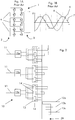
- a multilevel converter 1 has inputs 2, outputs 3 and capacitors 4 between the inputs 2; all the capacitors 4 have the same capacitance.
- the capacitors 4 are used to divide the input voltage in steps that are then combined to create a desired sinusoidal step modulated output voltage; in Figure 1B reference 5 indicates the grid voltage, reference 6 indicates the desired voltage and reference 7 indicates the output voltage considering a connection to the grid via an impedance (reactor or transformer).
- the capacitors 4 have different capacitance (also small differences can be relevant and could for example be due to defecting manufacturing or connections) the voltage steps are different from one another and the control of the output voltage can become problematic, because it would need a sophisticated control of the voltage distribution between the capacitors.
- An aspect of the present description is thus to provide a converter and an electric generator by which the control of the output voltage can be simplified, such that it is easier than with existing converters.
- the converter 10 ( Figure 2 ) comprises a plurality of input lines 11 and one or more output lines 12a, 12b, 12c.
- Each input line 11 is connected to a group 13 of supply circuits 14.
- the supply circuits 14 of each group 13 are in turn connected to different output lines 12a, 12b, 12c.
- each output line 12a, 12b, 12c is connected to one supply circuit 14 of each group 13; in other words each of the groups 13 includes a number of supply circuits 14 equal to the number of output lines 12a, 12b, 12c and each of these supply circuits 14 is connected to one output line 12a, 12b, 12c (this feature is anyhow not essential).
- the supply circuits 14 are arranged to supply the output lines 12a, 12b, 12c with a positive voltage or a negative voltage or a zero voltage.
- the converter 10 can also have input converters (input converters 15a, 15b, 15c operating as rectifiers in one energy direction only or as converters operating in two energy directions) or rectifiers 15a, 15b, 15c on each input line 11.
- the input converters or rectifiers are advantageous (but not mandatory) when the converter 10 (i.e. its input lines 11) is fed with an AC voltage.
- rectifier includes embodiments in which the rectifier can provide energy in two directions, such that in one direction it operates as a rectifier and in the other direction it operates as an inverter; these devices are well known in the art.
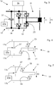
- the supply circuits 14 (see for example Figure 5 ) have an input 17 (preferably a DC input) and a first and a second branch 18, 19; for clarity Figures 6 and 7 show the two branches 18 and 19 separately; namely Figure 6 shows the branch 18 and Figure 7 shows the branch 19.
- the branches 18, 19 are both connected to the input 17 and have a common part 21 that is coupled to an output line 12a, 12b, 12c.
- the first and second branches 18, 19 have components 25 that allow selection of the current direction through the common part 21 or selection of the voltage that can be supplied to the output line.
- These components can non-exclusively be thyristors and/or thyristors with switch-off capacitors and diode/reactor oscillating circuits and/or IGBT and/or IGCT and/or GTO in a bidirectional configuration (or other bidirectional switching devices) and are connected to drive circuits 26.
- a capacitor 27 is connected between the connections 17a (+), 17b (-) of the input 17; this capacitor 27 is used to define the voltage steps of the output voltage and to store energy in the dc-link for reactive power control.
- the capacitors 27 are charged using separate charging devices 27a.
- a transformer 29 (see Figure 2 ) is provided and the connection between the supply circuits 14 and output lines 12a, 12b, 12c occurs via this transformer 29.
- This transformer 29 can have secondary windings insulated from one another.
- the operation is described with reference to the converter of figure 2 , supposing that the input lines 11 are connected to AC voltage sources and that the voltage supplied to each input line 11 is different from the voltage supplied to the other input lines.
- the voltage supplied via a first line is 1 time V (1V, downstream of the rectifier 15a)
- the voltage supplied via the second line is 3 times V (3V, downstream of the rectifier 15b)
- the voltage supplied via the third line is 8 times V (8V, downstream of the rectifier 15c); thus here and in the following 1V, 3V and 8V indicate that the voltage is 1 time, 3 times or 8 times a voltage V; typically the voltage is in the order to thousands of Volt.
- the voltages above defined can in different examples be achieved by a dedicated generator having outputs providing different voltages or a traditional generator whose outputs provide the same voltage (for example a usual three phase generator) but with a transformer connected at its outputs (all of the outputs or only some of them according to the needs) to obtain the desired voltages.
- 8V-3V-1V other combinations are feasible, for example 25V-8V-3V-1V to generate an output voltage with +/-37 voltage steps using the 4 input voltages 1Vac/1Vdc, 3Vac/3Vdc, 8Vac/8Vdc and 25Vac/25Vdc, and so on.
- the voltage at the input lines 11 can also be the same.
- the AC voltage supplied to each input line 11 is rectified by the rectifiers 15a, 15b, 15c, such that at the inputs 17 of the supply circuits 14 a DC voltage is provided.
- the two branches 18, 19 of the supply circuits 14 are arranged to allow current flow through the common part 21 in a different direction according to the needs.
- a current flow in a direction F1 can be achieved by activating the branch 18 ( Figure 6 ) and a current flow in the opposite direction F2 can be achieved by activating the branch 19 ( Figure 7 ).
- Each branch can be activated by opportunely driving the components 25.
- the components 25 can also be driven to prevent any current flow through the common part 21.
- the components 14 could also be driven such that they control the current flow through the common part 21 independently of the positive or negative voltage at the input 17.
- the drive circuit 26 can activate the first or second branch and can allow the flow of the current in the required direction as a function of the voltage at the connections 17a, 17b.
- the components 25 via the drive circuits 26 it is possible to have a current through the common part 21 in any of the desired direction (for example to generate reactive power versus the grid only) or no current.
- each group 13 Preferably all the supply circuits 14 of each group 13 are driven in parallel but with a delay, such that at each output line 12a, 12b, 12c the same voltage signal is obtained but these signals are out of phase, to achieve a three phase (or also less or more phases if needed) output.
- each group 13 of circuits 14 can inject in the output lines 12a, 12b, 12c a voltage originating from the corresponding input line.
- an embodiment of converter whose supply circuits 14 can supply different voltages for example ⁇ 1V (i.e. 1 time V), ⁇ 3V (i.e. 3 times V), ⁇ 8V (i.e. 8 times V) or 0 voltage (i.e. 0 times V) can built an output voltage in a broader range than when all the input lines have the same voltage.
- the output voltage at each of the output lines 12a, 12b, 12c is the combination (arithmetic sum) of the voltages injected by each group 13.
- the group 13 connected to the input line 11c of Figure 3 at voltage 8V (downstream of the rectifier 15c) can inject into the output lines 12a, 12b, 12c:
- Figure 9 shows a table of the possible voltage combinations to achieve the desired output voltages and Figure 8 shows an example of an output voltage that can be obtained by combining the voltages from each group 13.
- the amplitude of the output voltage A in Figure 8 can be controlled by excitation of the generator or by pulse width modulation of the supply circuits 14 or by phase angle control of the rectifiers 15a, 15b, 15c (implemented by input converters with for example thyristors instead of diodes) or by forced commutated rectifiers 15a, 15b, 15c (in this case input converters are used with GTO, IGBT, IGCT instead diodes) or by combination of these methods.
- the voltage needed at the input lines 11 of the converter 10 can be advantageously provided by an electric generator 30.
- the electric generator 30 comprises a stator 31 and a rotor 32.
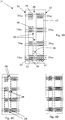
- the stator 31 has a plurality of windings 33 and each winding 33 has a plurality of phases 34 (the example shows a generator with four three-phase windings).
- Each phase 34 comprises two or more than two bars 35; the bars 35 are connected in series to define a bar series.
- Each phase 34 has a first connection 36 at one end and a second connection 37 at the other end thereof.
- the phases 34 also have at least a connection 38 (for example a third connection) in an intermediate position between the first and the second connection 36, 37.
- a connection 38 for example a third connection
- the intermediate connection 38 defines:
- first bar group 40 and second bar group 41 can include a different number of bars according to the needs and particular design.
- each phase 34 includes twelve bars 35
- the first group 40 includes four bars 35
- the second group 41 includes eight bars 35.
- the voltage at the connection 36 is 1Vac
- the voltage at the connection 37 is 2Vac (Vac means alternating voltage).
- the connections 38 can be star connected.
- connections 36, 37, 38 are three phase (or in general multi phase) connections.
- the electric generator 30 is particularly arranged to be connected to the converter 10 to define an arrangement in which:
- the group of windings 45 can include one or more groups of bars 40
- the group of windings 46 can include one or more groups of bars 40
- the group of windings 47 can include one or more groups of bars 41 according to the needs.
- the transformer 29 can have secondary windings insulated from one another, then the generator winding can be designed as shown in Figure 4B . If no transformer 29 is used, the generator 30 can have one of the two connections 38 that are star point connected on each phase 34 ( Figure 4C ) or it can have a delta connection on each 3-phase system ( Figure 4D ).
- the arrangement described can be implemented in a power plant such as the power plant schematically shown in Figure 12 .
- This power plant has an engine 50 such as a gas or steam turbine connected to an electric generator such as the electric generator 30 above described.
- the electric generator 30 is connected to the converter 10 that in turn is connected to an electric grid 53.
- the arrangement of the generator 30 and converter 10 is particularly advantageous during start up, because during start up only a limited power is usually needed from the grid to activate the generator 30 operating as a motor; in this case only some of the groups 45, 46, 47 of windings can be used according to the needs. For example only the group 45 or 46 or 47 or combination of two of them can be used; it is clear that when more power is needed also all the groups 45-47 of windings can be advantageously used.
- the rectifier 15a is designed with thyristors, IGBT, IGCT or GTO to operate in both energy directions (input converter).
- the other rectifiers 15b and 15c can be designed with diodes only (because only one energy direction is used). If the other groups are also used for start-up, the rectifiers 15b and 15c are designed with IGBT, IGCT or GTO thyristors (input converter) because two energy directions are used.
Landscapes
- Engineering & Computer Science (AREA)
- Power Engineering (AREA)
- Inverter Devices (AREA)
- Control Of Eletrric Generators (AREA)
Abstract
The converter (10) comprises a plurality of input lines (11) and one or more output lines (12a, 12b, 12c). Each input line (11) is connected to a group (13) of supply circuits (14) and the supply circuits (14) of each group (13) are connected to different output lines (12a, 12b, 12c). The electric generator (30) comprises a stator (31) and a rotor (32). The stator (31) has a plurality of windings (33). Each winding (33) has a plurality of phases (34). Each phase (34) comprises bars (35) connected in series. The phases (34) have a first connection (36) at one end, a second connection (37) at the other end and a third connection (38) in an intermediate position between the first and the second connection (36, 37).
Description
- The present description relates to a converter and an electric generator.
- In order to convert an input voltage with a frequency f1 into an output voltage with a frequency f2 multilevel converter can be used.
- With reference to
Figure 1A , amultilevel converter 1 hasinputs 2,outputs 3 andcapacitors 4 between theinputs 2; all thecapacitors 4 have the same capacitance. Thecapacitors 4 are used to divide the input voltage in steps that are then combined to create a desired sinusoidal step modulated output voltage; inFigure 1B reference 5 indicates the grid voltage, reference 6 indicates the desired voltage andreference 7 indicates the output voltage considering a connection to the grid via an impedance (reactor or transformer). - When the
capacitors 4 have different capacitance (also small differences can be relevant and could for example be due to defecting manufacturing or connections) the voltage steps are different from one another and the control of the output voltage can become problematic, because it would need a sophisticated control of the voltage distribution between the capacitors. - An aspect of the present description is thus to provide a converter and an electric generator by which the control of the output voltage can be simplified, such that it is easier than with existing converters.
- This and further aspects are attained by providing a converter and an electric generator in accordance with the accompanying claims.
- Further characteristics and advantages will be more apparent from the description of a preferred but non-exclusive embodiment of the converter and electric generator illustrated by way of a non-limiting example in the accompanying drawings, in which:
-
Figure 1A is an electric scheme of a known multilevel converter; -
Figure 1B shows the voltage combination implemented by the multilevel converter ofFigure 1A ; -
Figure 2 is an electric scheme of a converter; -
Figure 3 is a schematic view of a converter connected to an electric generator; -
Figure 4A is an electric scheme of an electric generator; -
Figure 4B is an enlarged part ofFigure 4A in an embodiment of the electric generator; -
Figure 4C is an alternative solution to the solution ofFigure 4B ; -
Figure 4D is a further alternative solution to the solution ofFigure 4B and 4C ; -
Figures 5 through 7 show electric schemes of a converter supply circuit; -
Figures 8 and 9 show the voltage combination implemented via the converter; -
Figure 10 is a schematic view of an electric generator (or motor); -
Figure 11 is a schematic view of one generator (or motor) phase; and -
Figure 12 is a schematic view of a power plant. - In the following the
converter 10 is described first. - The converter 10 (
Figure 2 ) comprises a plurality ofinput lines 11 and one ormore output lines - Each
input line 11 is connected to agroup 13 ofsupply circuits 14. Thesupply circuits 14 of eachgroup 13 are in turn connected todifferent output lines - Preferably, each
output line supply circuit 14 of eachgroup 13; in other words each of thegroups 13 includes a number ofsupply circuits 14 equal to the number ofoutput lines supply circuits 14 is connected to oneoutput line - The
supply circuits 14 are arranged to supply theoutput lines - The
converter 10 can also have input converters (input converters rectifiers input line 11. The input converters or rectifiers are advantageous (but not mandatory) when the converter 10 (i.e. its input lines 11) is fed with an AC voltage. In the following particular reference to a rectifier is made, but it is clear that the term rectifier includes embodiments in which the rectifier can provide energy in two directions, such that in one direction it operates as a rectifier and in the other direction it operates as an inverter; these devices are well known in the art. - The supply circuits 14 (see for example
Figure 5 ) have an input 17 (preferably a DC input) and a first and asecond branch Figures 6 and 7 show the twobranches Figure 6 shows thebranch 18 andFigure 7 shows thebranch 19. - The
branches input 17 and have acommon part 21 that is coupled to anoutput line - The first and
second branches components 25 that allow selection of the current direction through thecommon part 21 or selection of the voltage that can be supplied to the output line. - These components can non-exclusively be thyristors and/or thyristors with switch-off capacitors and diode/reactor oscillating circuits and/or IGBT and/or IGCT and/or GTO in a bidirectional configuration (or other bidirectional switching devices) and are connected to drive
circuits 26. - In addition, a
capacitor 27 is connected between theconnections 17a (+), 17b (-) of theinput 17; thiscapacitor 27 is used to define the voltage steps of the output voltage and to store energy in the dc-link for reactive power control. Preferably thecapacitors 27 are charged usingseparate charging devices 27a. - In a preferred embodiment, between the
supply circuits 14 and theoutput lines Figure 2 ) is provided and the connection between thesupply circuits 14 andoutput lines transformer 29. Thistransformer 29 can have secondary windings insulated from one another. - The operation of the converter in the embodiment described is the following.
- The operation is described with reference to the converter of
figure 2 , supposing that theinput lines 11 are connected to AC voltage sources and that the voltage supplied to eachinput line 11 is different from the voltage supplied to the other input lines. In the present example the voltage supplied via a first line is 1 time V (1V, downstream of therectifier 15a), the voltage supplied via the second line is 3 times V (3V, downstream of therectifier 15b) and the voltage supplied via the third line is 8 times V (8V, downstream of therectifier 15c); thus here and in the following 1V, 3V and 8V indicate that the voltage is 1 time, 3 times or 8 times a voltage V; typically the voltage is in the order to thousands of Volt. - The voltages above defined can in different examples be achieved by a dedicated generator having outputs providing different voltages or a traditional generator whose outputs provide the same voltage (for example a usual three phase generator) but with a transformer connected at its outputs (all of the outputs or only some of them according to the needs) to obtain the desired voltages.
- Naturally instead of 8V-3V-1V other combinations are feasible, for example 25V-8V-3V-1V to generate an output voltage with +/-37 voltage steps using the 4 input voltages 1Vac/1Vdc, 3Vac/3Vdc, 8Vac/8Vdc and 25Vac/25Vdc, and so on.
- Naturally instead of different voltages at each
input line 11 the voltage at theinput lines 11 can also be the same. - The AC voltage supplied to each
input line 11 is rectified by therectifiers inputs 17 of the supply circuits 14 a DC voltage is provided. - The two
branches supply circuits 14 are arranged to allow current flow through thecommon part 21 in a different direction according to the needs. - Namely, assuming that at the
connection 17a a positive voltage is provided and at theconnection 17b a negative voltage is provided, a current flow in a direction F1 can be achieved by activating the branch 18 (Figure 6 ) and a current flow in the opposite direction F2 can be achieved by activating the branch 19 (Figure 7 ). Each branch can be activated by opportunely driving thecomponents 25. Naturally thecomponents 25 can also be driven to prevent any current flow through thecommon part 21. - If no
rectifier supply circuits 14, thecomponents 14 could also be driven such that they control the current flow through thecommon part 21 independently of the positive or negative voltage at theinput 17. In other words, thedrive circuit 26 can activate the first or second branch and can allow the flow of the current in the required direction as a function of the voltage at theconnections components 25 via thedrive circuits 26 it is possible to have a current through thecommon part 21 in any of the desired direction (for example to generate reactive power versus the grid only) or no current. - Preferably all the
supply circuits 14 of eachgroup 13 are driven in parallel but with a delay, such that at eachoutput line - By appropriately driving all the
supply circuits 14 of all thegroups 13 it is possible to build the desired output voltage. - In fact, when the
supply circuits 14 are operated in parallel, eachgroup 13 ofcircuits 14 can inject in theoutput lines - In particular an embodiment of converter whose
supply circuits 14 can supply different voltages (for example ±1V (i.e. 1 time V), ±3V (i.e. 3 times V), ±8V (i.e. 8 times V) or 0 voltage (i.e. 0 times V) can built an output voltage in a broader range than when all the input lines have the same voltage. - The output voltage at each of the
output lines group 13. - In particular the
group 13 connected to theinput line 11a ofFigure 3 at voltage 1V (downstream of therectifier 15a) can inject into theoutput lines - 0 voltage;
- voltage +1V;
- voltage -1V.
- Likewise the
group 13 connected to theinput line 11b ofFigure 3 atvoltage 3V (downstream of therectifier 15b) can inject into theoutput lines - 0 voltage;
- voltage +3V;
- voltage -3V.
- The
group 13 connected to theinput line 11c ofFigure 3 atvoltage 8V (downstream of therectifier 15c) can inject into theoutput lines - 0 voltage;
- voltage +8V;
- voltage -8V.
- From the combination of these voltages each voltage between 0 and ±12 times V can be achieved; for example
Figure 9 shows a table of the possible voltage combinations to achieve the desired output voltages andFigure 8 shows an example of an output voltage that can be obtained by combining the voltages from eachgroup 13. In this Figure reference A indicates the output voltage and reference B indicates the voltage steps (-12 ... +12) and reference C, D, E indicate the actual status of thegroups - The amplitude of the output voltage A in
Figure 8 can be controlled by excitation of the generator or by pulse width modulation of thesupply circuits 14 or by phase angle control of therectifiers rectifiers - The voltage needed at the input lines 11 of the
converter 10 can be advantageously provided by anelectric generator 30. - The
electric generator 30 comprises astator 31 and arotor 32. - The
stator 31 has a plurality ofwindings 33 and each winding 33 has a plurality of phases 34 (the example shows a generator with four three-phase windings). - Each
phase 34 comprises two or more than twobars 35; thebars 35 are connected in series to define a bar series. - Each
phase 34 has afirst connection 36 at one end and asecond connection 37 at the other end thereof. - In addition, the
phases 34 also have at least a connection 38 (for example a third connection) in an intermediate position between the first and thesecond connection - Preferably, the
intermediate connection 38 defines: - a
first bar group 40 including 1/3 of the total number of bars (to generate the ac voltage 1vac), and - a
second bar group 41 including 2/3 of the total number of bars (to generate the ac voltage 2Vac). - Naturally the
first bar group 40 andsecond bar group 41 can include a different number of bars according to the needs and particular design. - In the example shown (see
Figure 11 ), eachphase 34 includes twelvebars 35, thefirst group 40 includes fourbars 35 and thesecond group 41 includes eightbars 35. - In particular, if the voltage at the
connection 36 is 1Vac, the voltage at theconnection 37 is 2Vac (Vac means alternating voltage). Theconnections 38 can be star connected. - Advantageously the
connections - The
electric generator 30 is particularly arranged to be connected to theconverter 10 to define an arrangement in which: - a first winding
group 45 of thegenerator 30 is connected to theinput line 11a; in the example of the Figures the windinggroup 45 includes the groups ofbars 40 of one multi-phase (three-phase) winding 33. The connection can be done via theconverter 15a to achieve a dc input voltage 1Vdc, - a second winding
group 46 of the generator connected to theinput line 11b; in the example of the Figures the windinggroup 46 includes the groups ofbars 40 of the other three multi-phase (three-phase) windings 33. The connection can be done for example via theconverter 15b to achieve a dc input voltage 3Vdc, - a third winding
group 47 of the generator is connected to theinput line 11c; in the example of the Figures the windinggroup 47 includes the groups ofbars 41 of all four multi-phase (three-phase) windings 33. The connection can be done for example via theconverter 15c to achieve a dc input voltage 8Vdc. - It is anyhow clear that in different embodiments the group of
windings 45 can include one or more groups ofbars 40, the group ofwindings 46 can include one or more groups ofbars 40, and the group ofwindings 47 can include one or more groups ofbars 41 according to the needs. - The
transformer 29 can have secondary windings insulated from one another, then the generator winding can be designed as shown inFigure 4B . If notransformer 29 is used, thegenerator 30 can have one of the twoconnections 38 that are star point connected on each phase 34 (Figure 4C ) or it can have a delta connection on each 3-phase system (Figure 4D ). - The arrangement described can be implemented in a power plant such as the power plant schematically shown in
Figure 12 . - This power plant has an
engine 50 such as a gas or steam turbine connected to an electric generator such as theelectric generator 30 above described. Theelectric generator 30 is connected to theconverter 10 that in turn is connected to anelectric grid 53. - Two modes of operation are possible for this power plant:
- normal operation, with the
engine 50 that activates thegenerator 30 that supplies electric power to theconverter 10; the converter converts the electric power received by the generator to adapt it to thegrid 53 and supplies it to thegrid 53; - start up, in which the grid supplies electric power to the converter that adapts the electric power to the features such as frequency needed by the generator for it to operate as an electric motor; the generator operating as an electric motor activates the
engine 50. - The arrangement of the
generator 30 andconverter 10 is particularly advantageous during start up, because during start up only a limited power is usually needed from the grid to activate thegenerator 30 operating as a motor; in this case only some of thegroups group - If the group of
windings 45 together with therectifier 15a is used only for start-up, therectifier 15a is designed with thyristors, IGBT, IGCT or GTO to operate in both energy directions (input converter). Theother rectifiers rectifiers - Naturally the features described may be independently provided from one another.
- In practice the materials used and the dimensions can be chosen at will according to requirements and to the state of the art.
-
- 1 multilevel converter
- 2 input
- 3 output
- 4 capacitors
- 5 input voltage
- 6 desired voltage
- 7 output voltage
- 10 converter
- 11, 11a, 11b, 11c input lines
- 12a, 12b, 12c output lines
- 13 group of supply circuits
- 14 supply circuit
- 15a, 15b, 15c rectifiers/input converters
- 17 input
- 17a, 17b connections
- 18 branch
- 19 branch
- 21 common part
- 25 components
- 26 drive circuits
- 27 capacitors
- 27a separate charging devices
- 29 transformer
- 30 electric generator
- 31 stator
- 32 rotor
- 33 windings
- 34 phases
- 36 first connection
- 37 second connection
- 38 third connection
- 40 group of bars
- 41 group of bars
- 45 group of windings
- 46 group of windings
- 47 group of windings
- 50 engine
- 53 grid
- F1, F2 current direction
- A output voltage
- B voltage steps
- C, D, E actual status of the
groups - -nV; n = 1, 3 or 8)
Claims (15)
- Converter (10) comprising a plurality of input lines (11) and one or more output lines (12a, 12b, 12c), characterised in that each input line (11) is connected to a group (13) of supply circuits (14) and the supply circuits (14) of each group (13) are connected to different output lines (12a, 12b, 12c).
- Converter (10) according to claim 1, characterised in that each output line (12a, 12b, 12c) is connected to a supply circuit (14) of each group (13).
- Converter (10) according to claim 1, characterised in that the supply circuits (14) are arranged to supply the output lines (12a, 12b, 12c) with a positive voltage or a negative voltage or a zero voltage.
- Converter (10) according to claim 1, characterised in that at least an input line (11) comprises an input converter (15a, 15b, 15c) operating as rectifier in one energy direction only or as converter operating in both energy directions or a rectifier.
- Converter (10) according to claim 1, characterised in that the supply circuits (14) have:- an input (17), a first and a second branch (18, 19) both connected to the input (17) and having a common part (21),- the common part (21) being coupled to a output line (12a, 12b, 12c).
- Converter (10) according to claim 5, characterised in that the first and second branches (18, 19) have components (25) that allow selection of the current direction (F1, F2) through the common part (21).
- Converter (10) according to claim 6, characterised in that the components (25) include thyristors and/or IGBT and/or IGCT and/or GTO in a bidirectional configuration for bidirectional power operation.
- Converter (10) according to claim 5, characterised in that a capacitor (27) is connected between connections (17a, 17b) of the input (17).
- Converter (10) according to claim 5, characterised in that the capacitor (27) is charged using a separate charging device (27a).
- Converter (10) according to claim 1, characterised in that between the supply circuits (14) and the output lines (12a, 12b, 12c) a transformer (29) is provided.
- Electric generator (30) comprising a stator (31) and a rotor (32),- the stator (31) having a plurality of windings (33),- each winding (33) having a plurality of phases (34),- each phase (34) comprising at least two bars (35),- each phase (34) having a first connection (36) and a second connection (37),characterised in that each phase (34) also has at least one third connection (38) in an intermediate position between the first and the second connection (36, 37).
- Electric generator (30) according to claim 11, characterised in that the first connection (36) is at one end and a second connection (37) is at the other end of each phase (34).
- Electric generator (30) according to claim 12, characterised in that the at least one intermediate connection (38) divides the bar series in:- a first bar group (40), and- a second bar group (41).
- Arrangement of an electric generator (30) and a converter (10),
the electric generator (30) comprising a stator (31) and a rotor (32),- the stator (31) having a plurality of windings (33),- each winding (33) having a plurality of phases (34),- each phase (34) comprising at least two bars (35),- each phase (34) having a first connection (36)the converter (10) comprising a plurality of input lines (11, 11a, 11b, 11c) and one or more output lines (12a, 12b, 12c),
and a second connection (37),
characterised in that:each phase (34) comprises at least one connection (38) in an intermediate position between the first and the second connection (36, 37) to define- a first bar group (40)- a second bar group (41)andeach input line (11, 11a, 11b, 11c) of the converter (10) is connected to a group (13) of supply circuits (14) and the supply circuits (14) of each group (13) are connected to different output lines (12a, 12b, 12c),
whereina first winding group (45) of the generator (30) is connected to a first input line (11a); the first winding group (45) including bars of the first bar groups (40) of at least a multi-phase winding (33),a second winding group (46) of the generator (30) is connected to a second input line (11b); the second winding group (46) including bars of the first bar groups (40) of at least a multi-phase windings (33),a third winding group (47) connected to a third input line (11c); the third winding group (47) including bars of the second bar groups (41) of at least a multi-phase windings (33). - Arrangement according to claim 14, characterised in that the generator includes four multi-phase windings, wherein
the first winding group (45) includes bars (35) of the first bar group (40) of one multi-phase winding (33), the second winding group (46) includes bars (35) of the first bar groups (40) of three multi-phase windings (33) different from the multi-phase windings (33) of the first winding group (45),
the third winding group (47) includes bars of the second bar groups (41) of all four multi-phase windings (33).
Priority Applications (4)
| Application Number | Priority Date | Filing Date | Title |
|---|---|---|---|
| EP12290040.0A EP2624430A1 (en) | 2012-01-31 | 2012-01-31 | Converter with multilevel output and multiwinding generator providing input |
| CA2804244A CA2804244C (en) | 2012-01-31 | 2013-01-28 | Converter and electric generator |
| US13/752,990 US9825551B2 (en) | 2012-01-31 | 2013-01-29 | Converter and electric generator in which groups of windings are used to generate output voltages according to a power requirement |
| DE102013001489A DE102013001489A1 (en) | 2012-01-31 | 2013-01-29 | Converter and electric generator |
Applications Claiming Priority (1)
| Application Number | Priority Date | Filing Date | Title |
|---|---|---|---|
| EP12290040.0A EP2624430A1 (en) | 2012-01-31 | 2012-01-31 | Converter with multilevel output and multiwinding generator providing input |
Publications (1)
| Publication Number | Publication Date |
|---|---|
| EP2624430A1 true EP2624430A1 (en) | 2013-08-07 |
Family
ID=45656771
Family Applications (1)
| Application Number | Title | Priority Date | Filing Date |
|---|---|---|---|
| EP12290040.0A Withdrawn EP2624430A1 (en) | 2012-01-31 | 2012-01-31 | Converter with multilevel output and multiwinding generator providing input |
Country Status (4)
| Country | Link |
|---|---|
| US (1) | US9825551B2 (en) |
| EP (1) | EP2624430A1 (en) |
| CA (1) | CA2804244C (en) |
| DE (1) | DE102013001489A1 (en) |
Cited By (1)
| Publication number | Priority date | Publication date | Assignee | Title |
|---|---|---|---|---|
| EP2884614A1 (en) * | 2013-12-13 | 2015-06-17 | Alstom Renovables España, S.L. | Multiphase generator-conversion systems |
Families Citing this family (2)
| Publication number | Priority date | Publication date | Assignee | Title |
|---|---|---|---|---|
| AU2022265567A1 (en) * | 2021-04-29 | 2023-11-09 | Terna S.P.A. | Ac/dc converter, dc/ac converter and dc/dc converter and method of control of the converter |
| US20250373184A1 (en) * | 2024-05-31 | 2025-12-04 | Honeywell International Inc. | Distributed multi-phase generator with multiple sub-phases and field angle modulation |
Citations (8)
| Publication number | Priority date | Publication date | Assignee | Title |
|---|---|---|---|---|
| US6236580B1 (en) * | 1999-04-09 | 2001-05-22 | Robicon Corporation | Modular multi-level adjustable supply with series connected active inputs |
| US20030043603A1 (en) * | 2001-09-04 | 2003-03-06 | Semikron Elektronik Gmbh | Frequency converter |
| EP1416604A2 (en) * | 2002-10-31 | 2004-05-06 | Bonus Energy A/S | Electric circuit for a driven generator with segmented stator |
| EP1976105A1 (en) * | 2007-03-30 | 2008-10-01 | ALSTOM Technology Ltd | Active generator control sequence |
| EP2157687A1 (en) * | 2008-08-19 | 2010-02-24 | Converteam Technology Ltd | Generators |
| US20100072824A1 (en) * | 2008-09-24 | 2010-03-25 | Mehdi Abolhassani | Modular multi-pulse transformer rectifier for use in asymmetric multi-level power converter |
| WO2010058028A2 (en) * | 2008-11-24 | 2010-05-27 | Aker Engineering & Technology As | Frequency convertor |
| EP2270968A1 (en) * | 2009-06-30 | 2011-01-05 | Vacon Oyj | Power Transmission Method and Power Transmission Apparatus |
Family Cites Families (25)
| Publication number | Priority date | Publication date | Assignee | Title |
|---|---|---|---|---|
| US2084177A (en) * | 1936-02-29 | 1937-06-15 | Gen Electric | Electric power system |
| US2123945A (en) * | 1937-02-23 | 1938-07-19 | Albert F Henderson | Necktie guide |
| DE1513993B2 (en) * | 1966-01-26 | 1976-02-12 | Beyersdorf, Hartwig, 2409 Scharbeutz | ELECTRIC MACHINE IN DISC DESIGN |
| DE2106146C3 (en) | 1971-02-10 | 1981-10-22 | Siemens Ag | Three-phase inverter arrangement |
| US3702429A (en) * | 1971-11-30 | 1972-11-07 | Gen Motors Corp | Cycloconverter silicon controlled rectifier gate-cathode circuit signal and power system |
| US3739213A (en) * | 1972-06-15 | 1973-06-12 | Gen Electric | Compact connection system for polyphase armature winding |
| US4246532A (en) * | 1978-06-07 | 1981-01-20 | Kokusan Denki Co., Ltd. | Synchronous generator |
| DE2921114A1 (en) * | 1979-05-25 | 1980-12-04 | Bosch Gmbh Robert | WINDING PROCESS FOR AN ELECTRIC GENERATOR AND THREE-PHASE GENERATOR PRODUCED AFTER THIS |
| US4719560A (en) * | 1986-03-28 | 1988-01-12 | Ford Horace B | Rotary phase generator and system |
| US5214371A (en) * | 1991-12-04 | 1993-05-25 | General Motors Corporation | Voltage regulator for variable speed permanent magnet alternators |
| US6018200A (en) * | 1994-09-14 | 2000-01-25 | Coleman Powermate, Inc. | Load demand throttle control for portable generator and other applications |
| US6333622B1 (en) * | 2000-05-16 | 2001-12-25 | General Electric Company | Synchronous generator having auxiliary power windings and variable frequency power source |
| US6909216B2 (en) * | 2002-05-29 | 2005-06-21 | Matsushita Electric Industrial Co., Ltd. | Motor generator |
| US6940202B1 (en) * | 2004-05-19 | 2005-09-06 | Visteon Global Technologies, Inc. | Electrical machine having a stator winding with a plurality of filars |
| US7659700B2 (en) * | 2005-02-04 | 2010-02-09 | Princeton Power Systems, Inc. | Charge-transfer apparatus and method |
| DE502006000995D1 (en) * | 2005-03-31 | 2008-08-07 | Alstom Technology Ltd | GENERATOR WITH HIGH PHASE ORDER |
| WO2006103155A1 (en) * | 2005-03-31 | 2006-10-05 | Alstom Technology Ltd | Matrix converter |
| JP2006345592A (en) * | 2005-06-07 | 2006-12-21 | Fuji Seratekku Kk | High power generator rotating at very low speed |
| FI118555B (en) * | 2006-05-22 | 2007-12-14 | Verteco Ltd | Control of a permanent magnet generator |
| KR100825323B1 (en) | 2007-03-05 | 2008-04-28 | 엘에스산전 주식회사 | Multi-level inverter using cascade method and unit cell power factor control device and its control method |
| WO2010036666A2 (en) | 2008-09-24 | 2010-04-01 | Teco-Westinghouse Motor Company | Modular multi-pulse transformer rectifier for use in multi-level power converter |
| US8279640B2 (en) | 2008-09-24 | 2012-10-02 | Teco-Westinghouse Motor Company | Modular multi-pulse transformer rectifier for use in symmetric multi-level power converter |
| WO2011135694A1 (en) * | 2010-04-28 | 2011-11-03 | 株式会社 日立製作所 | Power conversion device |
| DE102011002657A1 (en) * | 2011-01-13 | 2012-07-19 | Converteam Gmbh | Method for operating an inverter of an arrangement for generating electrical energy |
| EP2602924A1 (en) * | 2011-12-07 | 2013-06-12 | Alstom Technology Ltd. | Cycloconverter |
-
2012
- 2012-01-31 EP EP12290040.0A patent/EP2624430A1/en not_active Withdrawn
-
2013
- 2013-01-28 CA CA2804244A patent/CA2804244C/en not_active Expired - Fee Related
- 2013-01-29 US US13/752,990 patent/US9825551B2/en active Active
- 2013-01-29 DE DE102013001489A patent/DE102013001489A1/en not_active Withdrawn
Patent Citations (8)
| Publication number | Priority date | Publication date | Assignee | Title |
|---|---|---|---|---|
| US6236580B1 (en) * | 1999-04-09 | 2001-05-22 | Robicon Corporation | Modular multi-level adjustable supply with series connected active inputs |
| US20030043603A1 (en) * | 2001-09-04 | 2003-03-06 | Semikron Elektronik Gmbh | Frequency converter |
| EP1416604A2 (en) * | 2002-10-31 | 2004-05-06 | Bonus Energy A/S | Electric circuit for a driven generator with segmented stator |
| EP1976105A1 (en) * | 2007-03-30 | 2008-10-01 | ALSTOM Technology Ltd | Active generator control sequence |
| EP2157687A1 (en) * | 2008-08-19 | 2010-02-24 | Converteam Technology Ltd | Generators |
| US20100072824A1 (en) * | 2008-09-24 | 2010-03-25 | Mehdi Abolhassani | Modular multi-pulse transformer rectifier for use in asymmetric multi-level power converter |
| WO2010058028A2 (en) * | 2008-11-24 | 2010-05-27 | Aker Engineering & Technology As | Frequency convertor |
| EP2270968A1 (en) * | 2009-06-30 | 2011-01-05 | Vacon Oyj | Power Transmission Method and Power Transmission Apparatus |
Cited By (3)
| Publication number | Priority date | Publication date | Assignee | Title |
|---|---|---|---|---|
| EP2884614A1 (en) * | 2013-12-13 | 2015-06-17 | Alstom Renovables España, S.L. | Multiphase generator-conversion systems |
| WO2015086801A1 (en) * | 2013-12-13 | 2015-06-18 | Alstom Renewable Technologies | Multiphase generator-conversion systems |
| US10153642B2 (en) | 2013-12-13 | 2018-12-11 | Ge Renewable Technologies Wind B.V. | Multiphase generator-conversion systems |
Also Published As
| Publication number | Publication date |
|---|---|
| CA2804244A1 (en) | 2013-07-31 |
| CA2804244C (en) | 2018-02-13 |
| DE102013001489A1 (en) | 2013-08-01 |
| US20130194849A1 (en) | 2013-08-01 |
| US9825551B2 (en) | 2017-11-21 |
Similar Documents
| Publication | Publication Date | Title |
|---|---|---|
| US7928592B2 (en) | Wind turbine with parallel converters utilizing a plurality of isolated generator windings | |
| US7939959B2 (en) | Wind turbine with parallel converters utilizing a plurality of isolated transformer windings | |
| US6631080B2 (en) | Systems and methods for boosting DC link voltage in turbine generators | |
| US7460377B2 (en) | Matrix converter | |
| US6750633B2 (en) | Electrical circuit for generating a three-phase alternating current | |
| CN102810990B (en) | For dynamically changing rectification circuit and the corresponding control method of output electromotor | |
| US7324359B2 (en) | Circuit for converting alternating voltage into high-voltage direct voltage | |
| US9577544B2 (en) | Device and method for connecting an electric power generator to an HVDC transmission system | |
| RU2366062C2 (en) | Generator with high phase order | |
| US10027113B2 (en) | High-voltage DC voltage unit and method for operating a high-voltage DC voltage unit | |
| US12027940B2 (en) | Rectifier | |
| EP2605396A2 (en) | A track-bound vehicle inverter | |
| EP2780188A1 (en) | Power converter based on h-bridges | |
| US11482956B2 (en) | Arrangement comprising an asynchronous machine and method for operating same | |
| EP3123606B1 (en) | Electrical converter with high machine side common mode voltage | |
| EP2719888A1 (en) | Dual-DC bus starter/generator | |
| CA2804244C (en) | Converter and electric generator | |
| US20200244184A1 (en) | Control of delta-connected converter | |
| US11101755B2 (en) | Arrangement for injecting electric power into an AC network by means of an asynchronous machine, and method for operating the asynchronous machine | |
| EP2854271A2 (en) | Method and system for driving electric machines | |
| Kammerer et al. | Overload capability of the modular multilevel matrix converter for feeding high torque low speed drives | |
| Najafi et al. | Vienna rectifier and B4 inverter as PM WECS grid interface | |
| JP2019530414A (en) | AC current generation method by inverter of wind power generator | |
| EP3247037A1 (en) | A turbogenerator set | |
| Joshi et al. | Multi-level inverter for induction motor drives: implementation using reversing voltage topology |
Legal Events
| Date | Code | Title | Description |
|---|---|---|---|
| PUAI | Public reference made under article 153(3) epc to a published international application that has entered the european phase |
Free format text: ORIGINAL CODE: 0009012 |
|
| AK | Designated contracting states |
Kind code of ref document: A1 Designated state(s): AL AT BE BG CH CY CZ DE DK EE ES FI FR GB GR HR HU IE IS IT LI LT LU LV MC MK MT NL NO PL PT RO RS SE SI SK SM TR |
|
| AX | Request for extension of the european patent |
Extension state: BA ME |
|
| STAA | Information on the status of an ep patent application or granted ep patent |
Free format text: STATUS: THE APPLICATION IS DEEMED TO BE WITHDRAWN |
|
| 18D | Application deemed to be withdrawn |
Effective date: 20140208 |