EP2624313A2 - Solar panel module - Google Patents
Solar panel module Download PDFInfo
- Publication number
- EP2624313A2 EP2624313A2 EP12162118.9A EP12162118A EP2624313A2 EP 2624313 A2 EP2624313 A2 EP 2624313A2 EP 12162118 A EP12162118 A EP 12162118A EP 2624313 A2 EP2624313 A2 EP 2624313A2
- Authority
- EP
- European Patent Office
- Prior art keywords
- solar panel
- deflecting
- frame
- wind
- board
- Prior art date
- Legal status (The legal status is an assumption and is not a legal conclusion. Google has not performed a legal analysis and makes no representation as to the accuracy of the status listed.)
- Withdrawn
Links
- 238000007664 blowing Methods 0.000 claims abstract description 26
- 230000001154 acute effect Effects 0.000 claims description 8
- 238000010586 diagram Methods 0.000 description 17
- 230000007774 longterm Effects 0.000 description 2
- 239000000463 material Substances 0.000 description 2
- 230000002411 adverse Effects 0.000 description 1
- 230000001419 dependent effect Effects 0.000 description 1
- 238000011161 development Methods 0.000 description 1
- 230000018109 developmental process Effects 0.000 description 1
- 230000000694 effects Effects 0.000 description 1
- 230000007613 environmental effect Effects 0.000 description 1
- 239000004744 fabric Substances 0.000 description 1
- 239000003208 petroleum Substances 0.000 description 1
- 238000010248 power generation Methods 0.000 description 1
Images







Classifications
-
- H—ELECTRICITY
- H02—GENERATION; CONVERSION OR DISTRIBUTION OF ELECTRIC POWER
- H02S—GENERATION OF ELECTRIC POWER BY CONVERSION OF INFRARED RADIATION, VISIBLE LIGHT OR ULTRAVIOLET LIGHT, e.g. USING PHOTOVOLTAIC [PV] MODULES
- H02S20/00—Supporting structures for PV modules
- H02S20/20—Supporting structures directly fixed to an immovable object
- H02S20/22—Supporting structures directly fixed to an immovable object specially adapted for buildings
- H02S20/23—Supporting structures directly fixed to an immovable object specially adapted for buildings specially adapted for roof structures
- H02S20/24—Supporting structures directly fixed to an immovable object specially adapted for buildings specially adapted for roof structures specially adapted for flat roofs
-
- F—MECHANICAL ENGINEERING; LIGHTING; HEATING; WEAPONS; BLASTING
- F24—HEATING; RANGES; VENTILATING
- F24S—SOLAR HEAT COLLECTORS; SOLAR HEAT SYSTEMS
- F24S25/00—Arrangement of stationary mountings or supports for solar heat collector modules
- F24S25/10—Arrangement of stationary mountings or supports for solar heat collector modules extending in directions away from a supporting surface
-
- F—MECHANICAL ENGINEERING; LIGHTING; HEATING; WEAPONS; BLASTING
- F24—HEATING; RANGES; VENTILATING
- F24S—SOLAR HEAT COLLECTORS; SOLAR HEAT SYSTEMS
- F24S25/00—Arrangement of stationary mountings or supports for solar heat collector modules
- F24S25/70—Arrangement of stationary mountings or supports for solar heat collector modules with means for adjusting the final position or orientation of supporting elements in relation to each other or to a mounting surface; with means for compensating mounting tolerances
-
- H—ELECTRICITY
- H02—GENERATION; CONVERSION OR DISTRIBUTION OF ELECTRIC POWER
- H02S—GENERATION OF ELECTRIC POWER BY CONVERSION OF INFRARED RADIATION, VISIBLE LIGHT OR ULTRAVIOLET LIGHT, e.g. USING PHOTOVOLTAIC [PV] MODULES
- H02S20/00—Supporting structures for PV modules
- H02S20/20—Supporting structures directly fixed to an immovable object
- H02S20/22—Supporting structures directly fixed to an immovable object specially adapted for buildings
- H02S20/23—Supporting structures directly fixed to an immovable object specially adapted for buildings specially adapted for roof structures
-
- Y—GENERAL TAGGING OF NEW TECHNOLOGICAL DEVELOPMENTS; GENERAL TAGGING OF CROSS-SECTIONAL TECHNOLOGIES SPANNING OVER SEVERAL SECTIONS OF THE IPC; TECHNICAL SUBJECTS COVERED BY FORMER USPC CROSS-REFERENCE ART COLLECTIONS [XRACs] AND DIGESTS
- Y02—TECHNOLOGIES OR APPLICATIONS FOR MITIGATION OR ADAPTATION AGAINST CLIMATE CHANGE
- Y02B—CLIMATE CHANGE MITIGATION TECHNOLOGIES RELATED TO BUILDINGS, e.g. HOUSING, HOUSE APPLIANCES OR RELATED END-USER APPLICATIONS
- Y02B10/00—Integration of renewable energy sources in buildings
- Y02B10/10—Photovoltaic [PV]
-
- Y—GENERAL TAGGING OF NEW TECHNOLOGICAL DEVELOPMENTS; GENERAL TAGGING OF CROSS-SECTIONAL TECHNOLOGIES SPANNING OVER SEVERAL SECTIONS OF THE IPC; TECHNICAL SUBJECTS COVERED BY FORMER USPC CROSS-REFERENCE ART COLLECTIONS [XRACs] AND DIGESTS
- Y02—TECHNOLOGIES OR APPLICATIONS FOR MITIGATION OR ADAPTATION AGAINST CLIMATE CHANGE
- Y02E—REDUCTION OF GREENHOUSE GAS [GHG] EMISSIONS, RELATED TO ENERGY GENERATION, TRANSMISSION OR DISTRIBUTION
- Y02E10/00—Energy generation through renewable energy sources
- Y02E10/40—Solar thermal energy, e.g. solar towers
- Y02E10/47—Mountings or tracking
-
- Y—GENERAL TAGGING OF NEW TECHNOLOGICAL DEVELOPMENTS; GENERAL TAGGING OF CROSS-SECTIONAL TECHNOLOGIES SPANNING OVER SEVERAL SECTIONS OF THE IPC; TECHNICAL SUBJECTS COVERED BY FORMER USPC CROSS-REFERENCE ART COLLECTIONS [XRACs] AND DIGESTS
- Y02—TECHNOLOGIES OR APPLICATIONS FOR MITIGATION OR ADAPTATION AGAINST CLIMATE CHANGE
- Y02E—REDUCTION OF GREENHOUSE GAS [GHG] EMISSIONS, RELATED TO ENERGY GENERATION, TRANSMISSION OR DISTRIBUTION
- Y02E10/00—Energy generation through renewable energy sources
- Y02E10/50—Photovoltaic [PV] energy
Definitions
- This invention generally relates to a solar panel module according to the pre-characterizing clause of claim 1.
- the power generating efficiency of a solar panel is still limited due to some problems to be solved.
- the power generating efficiency of a solar panel is generally inversely proportional to its operating temperature.
- the higher the operating temperature of a solar panel the lower the power generating efficiency.
- the power generating efficiency would be adversely affected due to the environmental temperature changes and the temperature increase caused by substantially long-term power generation.
- the power generating efficiency is proportional to the amount of sunlight.
- the present invention aims at providing a solar panel module having a solar panel with high heat dissipating efficiency and an adjustable tilt angle.
- the claimed solar panel module includes a solar panel, a supporting stand and a deflecting device.
- the supporting stand is structurally connected to the solar panel for supporting the solar panel.
- the solar panel is disposed inclinedly, and the solar panel has a tilt angle with respect to a horizontal plane.
- the deflecting device is disposed underneath the solar panel for deflecting wind blowing from lateral directions toward a wind exiting direction, which faces a bottom surface of the solar panel.
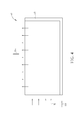
- FIG. 1 and FIG. 2 are schematic diagrams illustrating a solar panel module according to a first preferred embodiment of the present invention, where FIG. 1 is a front view of the solar panel module, and FIG. 2 is a cross-sectional view of the solar panel module.
- the solar panel module 10 of this embodiment includes a solar panel 20, a supporting stand 30 and a deflecting device 40.
- the solar panel 20 includes a plurality of solar cell units 20C.
- One end of the supporting stand 30 may be connected to the solar panel 20, while the other end of the solar supporting stand 30 may be disposed or fixed on the ground G or on the roof or wall of a building for supporting the solar panel 20 and making the solar panel 20 dispose at a tilt angle ⁇ with respect to the horizontal plane.
- the deflecting device 40 is disposed underneath the solar panel 20 for deflecting wind W blowing from lateral directions toward a wind exiting direction Dw facing a bottom surface 20S of the solar panel 20 to dissipate heat from the solar panel 20.
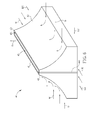
- FIG. 3 and FIG. 4 are schematic diagrams illustrating a deflecting device of the solar panel module of FIG. 1 and FIG. 2 according to a first preferred configuration, where FIG. 3 is an oblique diagram of the deflecting device, and FIG. 4 is a cross-sectional view of the deflecting device.
- the deflecting device 40 of the first configuration includes a first deflecting board 41 and a second deflecting board 42 disposed underneath the solar panel 20 and opposite to each other.
- the first deflecting board 41 and the second deflecting board 42 are used to deflect wind W blowing from a first lateral direction D1 toward the wind exiting direction Dw, and to deflect wind W blowing from a second lateral direction D2 opposite to the first lateral direction D1 toward the wind exiting direction Dw, respectively.
- At least one of the first deflecting board 41 and the second deflecting board 42 preferably has a curved surface (i.e.
- the first deflecting board 41 and/or the second deflecting board 42 has a curved surface) for deflecting wind W blowing from the first lateral direction D1 and the second lateral direction D2 toward the wind exiting direction Dw, and the radius of curvature of the curved surface may be modified based on the requirement of the deflecting effect.
- the first deflecting board 41 and/or the second deflecting board 42 are not limited to have a curved surface, and may have an inclined surface for instance.
- the deflecting device 40 may further include a third deflecting board 42 disposed underneath the solar panel 20 and between the first deflecting board 41 and the second deflecting board 42.
- the third deflecting board 43 is used to deflect wind W blowing from a third lateral direction D3 perpendicular to the first lateral direction D1 toward the wind exiting direction Dw.
- FIGs. 5-8 are schematic diagrams illustrating a deflecting device of the solar panel module of FIG. 1 and FIG. 2 according to a second preferred configuration, where FIG. 5 and FIG. 6 are oblique views of the deflecting device, and FIG. 7 and FIG. 8 are cross-sectional views of the deflecting device.
- the deflecting device 40 of the second configuration different from the first preferred configuration, in addition to the first deflecting board 41, the second deflecting board 42 and the third deflecting board 43, the deflecting device 40 of the second configuration further includes a fourth deflecting board 44.
- the third deflecting board 43 and the fourth deflecting board 44 are disposed opposite to each other, and between the first deflecting board 41 and the second deflecting board 42.
- the first deflecting board 41, the second deflecting board 42, the third deflecting board 43 and the fourth deflecting board 44 form a space and an opening 45 facing the bottom surface 20S (as shown in FIG. 1 ) of the solar panel 20.
- the third deflecting board 43 is used to deflect wind W blowing from a third lateral direction D3 perpendicular to the first lateral direction D1 toward the wind exiting direction Dw
- the fourth deflecting board 44 is used to deflect wind W blowing from a fourth lateral direction D4 opposite to the third lateral direction D3 toward the wind exiting direction Dw.
- the deflecting device 40 may further include a first check valve 431 disposed on the third deflecting board 43, and a second check valve 441 disposed on the fourth deflecting board 44.
- the first check valve 431 allows wind W blowing from the third lateral direction D3 entering the space, and wind W entering the space through the first check valve 431 is deflected by the fourth deflecting board 44, and goes through the opening 45 toward the wind exiting direction Dw to dissipate heat from the solar panel 20.
- the second check valve 441 allows wind W blowing from the fourth lateral direction D4 entering the space, and wind W entering the space through the second check valve 441 is deflected by the third deflecting board 43, and goes through the opening 45 toward the wind exiting direction Dw to dissipate heat from the solar panel 20.
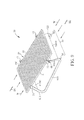
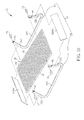
- FIGs. 9-12 are schematic diagrams illustrating a solar panel module according to a second preferred embodiment of the present invention, where FIG. 9 is an oblique view of the solar panel module, FIG. 10 is an exploded view of the solar panel module, FIG. 11 is a left side view of the solar panel module, and FIG. 12 is a right side view of the solar panel module.
- the solar panel module 50 of this embodiment includes a solar panel 20, a supporting stand 60 and a deflecting device 80.
- the solar panel 20 includes a plurality of solar cell units 20C, and the solar panel 20 has a first side 21 and a second side 22 disposed in parallel and opposite to each other.
- the supporting stand 60 includes a first frame 61 and a second frame 62.
- the first frame 61 includes a first part 611 connected to the first side 21 of the solar panel 20, and a second part 612 adjustably connected to the first side 21 of the solar panel 20 for adjusting the tilt angle ⁇ of the solar panel 20.
- the second frame 62 includes a first part 621 connected to the second side 22 of the solar panel 20, and a second part 622 adjustably connected to the second side 22 of the solar panel 20 for adjusting the tilt angle ⁇ of the solar panel 20.
- the first frame 61 may further include a third part 613 connected to the first part 611 and the second part 612 to form a U-shaped (or U-shape like) structure.
- the first part 611 and the third part 613 of the first frame 61 have an acute included angle ⁇ 1, and the second part 612 and the third part 613 of the first frame 61 have an acute included angle ⁇ 2.
- the second frame 62 may further include a third part 623 connected to the first part 621 and the second part 622 to form a U-shaped (or U-shape like) structure, the first part 621 and the third part 623 of the second frame 62 have an acute included angle ⁇ 1, and the second part 622 and the third part 623 of the second frame 62 have an acute included angle ⁇ 2.
- the first frame 61 is preferably a monolithically-formed frame
- the second frame 62 is preferably a monolithically-formed frame, but not limited thereto.
- the first frame 61 may be formed by a plurality of pieces
- the second frame 62 may be formed by a plurality of pieces.
- the solar panel module 50 may further include a plurality of first fastening devices 71 and a plurality of second fastening devices 72.
- the first fastening devices 71 and the second fastening devices 72 may be, for example, screws or rivets, but not limited thereto.
- the first part 611 of the first frame 61 and the first part 621 of the second frame 62 have at least one first hole 65, respectively, and the second part 612 of the first frame 61 and the second part 622 of the second frame 62 have a plurality of second holes 66, respectively.
- the first fastening devices 71 can be inserted into the first holes 65 for connecting the first part 611 of the first frame 61 with the first side 21 of the solar panel 20, and for connecting the first part 621 of the second frame 62 with the second side 22 of the solar panel 20.
- the second fastening devices 72 can be selectively inserted into a portion of the second holes 66 for adjustably connecting the second part 612 of the first frame 61 with the first side 21 of the solar panel 20, and for adjustably connecting the second part 622 of the second frame 62 with the second side 22 of the solar panel 20.
- the second fastening devices 72 can be inserted into proper second holes 66 to adjust the tilt angle ⁇ of the solar panel 20 based on different incident angle of sunlight for improving power generating efficiency.
- the deflecting device 80 is disposed underneath the solar panel 20, and the deflecting device 80 includes a first deflecting board 81 and a second deflecting board 82.
- the first deflecting 81 is fixed on the first part 611 of the first frame 61 and the first part 621 of the second frame 62 for deflecting wind W blowing from the first lateral direction D1 toward the wind exiting direction Dw.
- the second deflecting board 82 is fixed on the second part 612 of the first frame 61 and the second part 622 of the second frame 62 for deflecting wind W blowing from the second lateral direction D2 opposite to the first lateral direction D1 toward the wind exiting direction Dw.
- the first deflecting board 81 and the second deflecting board 82 may be, for example, wind-shielding cloth or canvas, but not limited thereto.
- the material of the first deflecting board 81 and the second deflecting board 82 may also be other soft or hard wind-shielding materials.
- the supporting stand of the second preferred embodiment may also be used to support the solar panel of the first preferred embodiment.
- the deflecting device of the solar panel module of the present invention is able to deflect wind blowing from lateral directions toward the bottom surface of the solar panel, and thus the heat dissipating efficiency of the solar panel module is dramatically improved. Accordingly, power generating efficiency can be maintained after long-term operation because the solar panel can be kept at proper operating temperature.
- the supporting stand of the solar panel module has an adjustable tilt angle design, making it possible to adjust the tilt angle of the solar panel based on the incident angle of sunlight.
Landscapes
- Engineering & Computer Science (AREA)
- Architecture (AREA)
- Structural Engineering (AREA)
- Civil Engineering (AREA)
- Chemical & Material Sciences (AREA)
- Thermal Sciences (AREA)
- Physics & Mathematics (AREA)
- Combustion & Propulsion (AREA)
- Mechanical Engineering (AREA)
- General Engineering & Computer Science (AREA)
- Sustainable Energy (AREA)
- Sustainable Development (AREA)
- Life Sciences & Earth Sciences (AREA)
- Photovoltaic Devices (AREA)
Abstract
Description
- This invention generally relates to a solar panel module according to the pre-characterizing clause of
claim 1. - Since petroleum resources on Earth are limited, energy demands have shifted toward alternative energies dramatically in recently years. Among the alternative energy sources, solar energy shows the most promising potential. In practical application, the power generating efficiency of a solar panel is still limited due to some problems to be solved. First, the power generating efficiency of a solar panel is generally inversely proportional to its operating temperature. Thus, the higher the operating temperature of a solar panel, the lower the power generating efficiency. Accordingly, even in areas with sufficiency sunlight, the power generating efficiency would be adversely affected due to the environmental temperature changes and the temperature increase caused by substantially long-term power generation. In addition, the power generating efficiency is proportional to the amount of sunlight. However, the incident angle of sunlight in areas of different latitudes is different, and the incident angle varies at different time in a day because the rotation axis of the Earth is tilted. Therefore, a solar panel module disposed in a stationary manner would suffer from low power generating efficiency because sunlight does not enter the solar panel perpendicularly at most of time.
- This in mind, the present invention aims at providing a solar panel module having a solar panel with high heat dissipating efficiency and an adjustable tilt angle.
- This is achieved by a solar panel module according to the pre-characterizing clause of
claim 1. The dependent claims pertain to corresponding further developments and improvements. - As will be seen more clearly from the detailed description following below, the claimed solar panel module includes a solar panel, a supporting stand and a deflecting device. The supporting stand is structurally connected to the solar panel for supporting the solar panel. The solar panel is disposed inclinedly, and the solar panel has a tilt angle with respect to a horizontal plane. The deflecting device is disposed underneath the solar panel for deflecting wind blowing from lateral directions toward a wind exiting direction, which faces a bottom surface of the solar panel.
- In the following, the invention is further illustrated by way of example, taking reference to the accompanying drawings thereof:
-
FIG. 1 is a schematic, front view diagram illustrating a solar panel module according to a first preferred embodiment of the present invention, -
FIG. 2 is a schematic, side view diagram illustrating a solar panel module according to a first preferred embodiment of the present invention, -
FIG. 3 is a schematic, oblique diagram illustrating a deflecting device of the solar panel module according to a first preferred configuration, -
FIG. 4 is a schematic, side view diagram illustrating a deflecting device of the solar panel module according to a first preferred configuration, -
FIG. 5 is a schematic, oblique diagram illustrating a deflecting device of the solar panel module according to a second preferred configuration, -
FIG. 6 is a schematic, oblique diagram illustrating a deflecting device of the solar panel module according to a second preferred configuration, -
FIG. 7 is a schematic, cross-sectional view diagram illustrating a deflecting device of the solar panel module according to a second preferred configuration, -
FIG. 8 is a schematic, cross-sectional view diagram illustrating a deflecting device of the solar panel module according to a second preferred configuration, -
FIG. 9 is a schematic, oblique diagram illustrating a solar panel module according to a second preferred embodiment of the present invention, -
FIG. 10 is a schematic, exploded view diagram illustrating a solar panel module according to a second preferred embodiment of the present invention, -
FIG. 11 is a schematic, left side view diagram illustrating a solar panel module according to a second preferred embodiment of the present invention, and -
FIG. 12 is a schematic, right side view diagram illustrating a solar panel module according to a second preferred embodiment of the present invention. - Please refer to
FIG. 1 andFIG. 2 .FIG. 1 andFIG. 2 are schematic diagrams illustrating a solar panel module according to a first preferred embodiment of the present invention, whereFIG. 1 is a front view of the solar panel module, andFIG. 2 is a cross-sectional view of the solar panel module. As shown inFIG. 1 andFIG. 2 , thesolar panel module 10 of this embodiment includes asolar panel 20, a supportingstand 30 and adeflecting device 40. Thesolar panel 20 includes a plurality ofsolar cell units 20C. One end of the supportingstand 30 may be connected to thesolar panel 20, while the other end of the solar supportingstand 30 may be disposed or fixed on the ground G or on the roof or wall of a building for supporting thesolar panel 20 and making thesolar panel 20 dispose at a tilt angle θ with respect to the horizontal plane. Thedeflecting device 40 is disposed underneath thesolar panel 20 for deflecting wind W blowing from lateral directions toward a wind exiting direction Dw facing abottom surface 20S of thesolar panel 20 to dissipate heat from thesolar panel 20. - Please refer to
FIG. 3 andFIG. 4 , as well asFIG. 1 andFIG. 2 .FIG. 3 andFIG. 4 are schematic diagrams illustrating a deflecting device of the solar panel module ofFIG. 1 andFIG. 2 according to a first preferred configuration, whereFIG. 3 is an oblique diagram of the deflecting device, andFIG. 4 is a cross-sectional view of the deflecting device. As shown inFIG. 3 , thedeflecting device 40 of the first configuration includes afirst deflecting board 41 and asecond deflecting board 42 disposed underneath thesolar panel 20 and opposite to each other. Thefirst deflecting board 41 and thesecond deflecting board 42 are used to deflect wind W blowing from a first lateral direction D1 toward the wind exiting direction Dw, and to deflect wind W blowing from a second lateral direction D2 opposite to the first lateral direction D1 toward the wind exiting direction Dw, respectively. At least one of thefirst deflecting board 41 and thesecond deflecting board 42 preferably has a curved surface (i.e. thefirst deflecting board 41 and/or thesecond deflecting board 42 has a curved surface) for deflecting wind W blowing from the first lateral direction D1 and the second lateral direction D2 toward the wind exiting direction Dw, and the radius of curvature of the curved surface may be modified based on the requirement of the deflecting effect. Thefirst deflecting board 41 and/or thesecond deflecting board 42 are not limited to have a curved surface, and may have an inclined surface for instance. In addition, as shown inFIG. 3 andFIG. 4 , thedeflecting device 40 may further include athird deflecting board 42 disposed underneath thesolar panel 20 and between thefirst deflecting board 41 and thesecond deflecting board 42. Thethird deflecting board 43 is used to deflect wind W blowing from a third lateral direction D3 perpendicular to the first lateral direction D1 toward the wind exiting direction Dw. - Please refer to
FIGs. 5-8 , as well asFIG. 1 andFIG. 2 .FIGs. 5-8 are schematic diagrams illustrating a deflecting device of the solar panel module ofFIG. 1 andFIG. 2 according to a second preferred configuration, whereFIG. 5 andFIG. 6 are oblique views of the deflecting device, andFIG. 7 andFIG. 8 are cross-sectional views of the deflecting device. As shown inFIGs. 5-8 , different from the first preferred configuration, in addition to thefirst deflecting board 41, thesecond deflecting board 42 and thethird deflecting board 43, thedeflecting device 40 of the second configuration further includes afourth deflecting board 44. Thethird deflecting board 43 and thefourth deflecting board 44 are disposed opposite to each other, and between thefirst deflecting board 41 and thesecond deflecting board 42. Thefirst deflecting board 41, thesecond deflecting board 42, thethird deflecting board 43 and thefourth deflecting board 44 form a space and anopening 45 facing thebottom surface 20S (as shown inFIG. 1 ) of thesolar panel 20. Thethird deflecting board 43 is used to deflect wind W blowing from a third lateral direction D3 perpendicular to the first lateral direction D1 toward the wind exiting direction Dw, and thefourth deflecting board 44 is used to deflect wind W blowing from a fourth lateral direction D4 opposite to the third lateral direction D3 toward the wind exiting direction Dw. In the second configuration, thedeflecting device 40 may further include afirst check valve 431 disposed on thethird deflecting board 43, and asecond check valve 441 disposed on thefourth deflecting board 44. As shown inFIG. 5 andFIG. 7 , thefirst check valve 431 allows wind W blowing from the third lateral direction D3 entering the space, and wind W entering the space through thefirst check valve 431 is deflected by thefourth deflecting board 44, and goes through theopening 45 toward the wind exiting direction Dw to dissipate heat from thesolar panel 20. As shown inFIG. 6 andFIG. 8 , thesecond check valve 441 allows wind W blowing from the fourth lateral direction D4 entering the space, and wind W entering the space through thesecond check valve 441 is deflected by thethird deflecting board 43, and goes through theopening 45 toward the wind exiting direction Dw to dissipate heat from thesolar panel 20. - Please refer to
FIGs. 9-12. FIGs. 9-12 are schematic diagrams illustrating a solar panel module according to a second preferred embodiment of the present invention, whereFIG. 9 is an oblique view of the solar panel module,FIG. 10 is an exploded view of the solar panel module,FIG. 11 is a left side view of the solar panel module, andFIG. 12 is a right side view of the solar panel module. As shown inFIGs. 9-12 , thesolar panel module 50 of this embodiment includes asolar panel 20, a supportingstand 60 and adeflecting device 80. Thesolar panel 20 includes a plurality ofsolar cell units 20C, and thesolar panel 20 has afirst side 21 and asecond side 22 disposed in parallel and opposite to each other. The supportingstand 60 includes afirst frame 61 and asecond frame 62. Thefirst frame 61 includes afirst part 611 connected to thefirst side 21 of thesolar panel 20, and asecond part 612 adjustably connected to thefirst side 21 of thesolar panel 20 for adjusting the tilt angle θ of thesolar panel 20. Thesecond frame 62 includes afirst part 621 connected to thesecond side 22 of thesolar panel 20, and asecond part 622 adjustably connected to thesecond side 22 of thesolar panel 20 for adjusting the tilt angle θ of thesolar panel 20. In this embodiment, thefirst frame 61 may further include athird part 613 connected to thefirst part 611 and thesecond part 612 to form a U-shaped (or U-shape like) structure. Thefirst part 611 and thethird part 613 of thefirst frame 61 have an acute included angle α1, and thesecond part 612 and thethird part 613 of thefirst frame 61 have an acute included angle α2. Thesecond frame 62 may further include athird part 623 connected to thefirst part 621 and thesecond part 622 to form a U-shaped (or U-shape like) structure, thefirst part 621 and thethird part 623 of thesecond frame 62 have an acute included angle β1, and thesecond part 622 and thethird part 623 of thesecond frame 62 have an acute included angle β2. In this embodiment, thefirst frame 61 is preferably a monolithically-formed frame, and thesecond frame 62 is preferably a monolithically-formed frame, but not limited thereto. For example, thefirst frame 61 may be formed by a plurality of pieces, and thesecond frame 62 may be formed by a plurality of pieces. - The
solar panel module 50 may further include a plurality offirst fastening devices 71 and a plurality ofsecond fastening devices 72. Thefirst fastening devices 71 and thesecond fastening devices 72 may be, for example, screws or rivets, but not limited thereto. In addition, thefirst part 611 of thefirst frame 61 and thefirst part 621 of thesecond frame 62 have at least onefirst hole 65, respectively, and thesecond part 612 of thefirst frame 61 and thesecond part 622 of thesecond frame 62 have a plurality ofsecond holes 66, respectively. Thefirst fastening devices 71 can be inserted into thefirst holes 65 for connecting thefirst part 611 of thefirst frame 61 with thefirst side 21 of thesolar panel 20, and for connecting thefirst part 621 of thesecond frame 62 with thesecond side 22 of thesolar panel 20. Thesecond fastening devices 72 can be selectively inserted into a portion of thesecond holes 66 for adjustably connecting thesecond part 612 of thefirst frame 61 with thefirst side 21 of thesolar panel 20, and for adjustably connecting thesecond part 622 of thesecond frame 62 with thesecond side 22 of thesolar panel 20. Specifically, in this embodiment, thesecond fastening devices 72 can be inserted into propersecond holes 66 to adjust the tilt angle θ of thesolar panel 20 based on different incident angle of sunlight for improving power generating efficiency. - The deflecting
device 80 is disposed underneath thesolar panel 20, and the deflectingdevice 80 includes a first deflectingboard 81 and a second deflectingboard 82. The first deflecting 81 is fixed on thefirst part 611 of thefirst frame 61 and thefirst part 621 of thesecond frame 62 for deflecting wind W blowing from the first lateral direction D1 toward the wind exiting direction Dw. Thesecond deflecting board 82 is fixed on thesecond part 612 of thefirst frame 61 and thesecond part 622 of thesecond frame 62 for deflecting wind W blowing from the second lateral direction D2 opposite to the first lateral direction D1 toward the wind exiting direction Dw. In this embodiment, the first deflectingboard 81 and the second deflectingboard 82 may be, for example, wind-shielding cloth or canvas, but not limited thereto. The material of the first deflectingboard 81 and the second deflectingboard 82 may also be other soft or hard wind-shielding materials. It is noted that the supporting stand of the second preferred embodiment may also be used to support the solar panel of the first preferred embodiment. - In summary, the deflecting device of the solar panel module of the present invention is able to deflect wind blowing from lateral directions toward the bottom surface of the solar panel, and thus the heat dissipating efficiency of the solar panel module is dramatically improved. Accordingly, power generating efficiency can be maintained after long-term operation because the solar panel can be kept at proper operating temperature. In addition, the supporting stand of the solar panel module has an adjustable tilt angle design, making it possible to adjust the tilt angle of the solar panel based on the incident angle of sunlight.
Claims (13)
- A solar panel module (10, 50), characterized by:a solar panel (20);a supporting stand (30, 60), structurally connected to the solar panel (20), for
supporting the solar panel (20), wherein the solar panel (20) is disposed inclinedly, and the solar panel (20) has a tilt angle (8) with respect to a horizontal plane; anda deflecting device (40, 80), disposed underneath the solar panel (20), for
deflecting wind (W) blowing from lateral directions toward a wind exiting direction (Dw), wherein the wind exiting direction (Dw) faces a bottom surface (20S) of the solar panel (20). - The solar panel module (10) of claim 1, characterized in that the deflecting device (40) comprises a first deflecting board (41) and a second deflecting board (42) disposed underneath the solar panel (20) and opposite to each other, for deflecting the wind (W) blowing from a first lateral direction (D1) toward the wind exiting direction (Dw) and deflecting the wind (W) blowing from a second lateral direction (D2), opposite to the first lateral direction (D1), toward the wind exiting direction (Dw), respectively.
- The solar panel module (10) of claim 2, characterized in that the deflecting device (40) further comprises a third deflecting board (43), disposed underneath the solar panel (20) and between the first deflecting board (41) and the second deflecting board (42), for deflecting the wind (W) blowing from a third lateral direction (D3), substantially perpendicular to the first lateral direction (D1), toward the wind exiting direction (Dw).
- The solar panel module (10) of claim 2, characterized in that the deflecting device (40) further comprises a third deflecting board (43) and a fourth deflecting board (44), disposed underneath the solar panel (20), opposite to each other and between the first deflecting board (41) and the second deflecting board (42), and the first deflecting board (41), the second deflecting board (42), the third deflecting board (43) and the fourth deflecting board (44) form a space, and an opening (45) facing the bottom surface (20S) of the solar panel (20).
- The solar panel module (10) of claim 4, characterized in that the third deflecting board (43) is used to deflect the wind (W) blowing from a third lateral direction (D3), substantially perpendicular to the first lateral direction (D1), toward the wind exiting direction (Dw), and the fourth deflecting board (44) is used to deflect wind (W) blowing from a fourth lateral direction, opposite to the third lateral direction (D3), toward the wind exiting direction (Dw).
- The solar panel module (10) of claim 4, characterized in that the deflecting device (40) comprises a first check valve (431) disposed on the third deflecting board (43), and a second check valve (432) disposed on the fourth deflecting board (44), wherein the first check valve (431) is used to allow the wind (W) blowing from the third lateral direction (D3) entering the space, and the wind (W) entering the space through the first check valve (431) is deflected by the fourth deflecting board (44), and goes through the opening (45) toward the wind exiting direction (Dw), the second check valve (432) is used to allow the wind (W) blowing from the fourth lateral direction entering the space, and the wind (W) entering the space through the second check valve (432) is deflected by the third deflecting board (43), and goes through the opening (45) toward the wind exiting direction (Dw).
- The solar panel module (10) of claim 2, characterized in that the first deflecting board (41) and/or the second deflecting board (42) has a curved surface.
- The solar panel module (50) of claim 1, characterized in that the solar panel (20) has a first side (21) and a second side (22) disposed in parallel and opposite to each other, the supporting stand (60) comprises a first frame (61) and a second frame (62), the first frame (61) comprises a first part (611) connected to the first side (21) of the solar panel (20), and a second part (612) adjustably connected to the first side (21) of the solar panel (20) for adjusting the tilt angle (θ) of the solar panel (20), the second frame (62) includes a first part (621) connected to the second side (22) of the solar panel (20), and a second part (622) adjustably connected to the second side (22) of the solar panel (20) for adjusting the tilt angle (θ) of the solar panel (20).
- The solar panel module (50) of claim 8, characterized in that the first frame (61) further comprises a third part (613) connected to the first part (611) and the second part (612) to form a U-shaped structure, the first part (611) and the third part (613) of the first frame (61) have an acute included angle (α1), and the second part (612) and the third part (613) of the first frame (61) have an acute included angle (α2), and wherein the second frame (62) further comprises a third part (623) connected to the first part (621) and the second part (622) to form a U-shaped structure, the first part and the third part (623) of the second frame (62) have an acute included angle (β1), and the second part (622) and the third part (623) of the second frame (62) have an acute included angle (β2).
- The solar panel module (50) of claim 9, characterized in that the first frame (61) is a monolithically-formed frame, and the second frame (62) is a monolithically-formed frame.
- The solar panel module (50) of claim 8, characterized by a plurality of first fastening devices (71) and a plurality of second fastening devices (72), wherein the first part (611) of the first frame (61) and the first part (621) of the second frame (62) have at least one first hole (65), respectively, the second part (612) of the first frame (61) and the second part (622) of the second frame (62) have a plurality of second holes (66), respectively, wherein the first fastening devices (71) are inserted into the first hole (65)s for connecting the first part (611) of the first frame (61) with the first side (21) of the solar panel (20), and for connecting the first part (621) of the second frame (62) with the second side (22) of the solar panel (20), and the second fastening devices (72) are selectively inserted into a portion of the second holes (66) for adjustably connecting the second part (612) of the first frame (61) with the first side (21) of the solar panel (20), and for adjustably connecting the second part (622) of the second frame (62) with the second side (22) of the solar panel (20).
- The solar panel module (50) of claim 8, characterized in that the deflecting device (80) comprises a first deflecting board (81) and a second deflecting board (82), the first deflecting board (81) is fixed on the first part (611) of the first frame (61) and the first part (621) of the second frame (62) for deflecting the wind (W) blowing from a first lateral direction (D1) toward the wind exiting direction (Dw), and the second deflecting board (82) is fixed on the second part (612) of the first frame (61) and the second part (622) of the second frame (62) for deflecting the wind (W) blowing from a second lateral direction (D2), opposite to the first lateral direction (D1), toward the wind exiting direction (Dw).
- The solar panel module (10) of claim 8, characterized in that the deflecting device (40) comprises a first deflecting board (41) and a second deflecting board (42), the first deflecting board (41) is fixed on the first part (611) of the first frame (61) and the second part (612) of the first frame (61) for deflecting the wind (W) blowing from a first lateral direction (D1) toward the wind exiting direction (Dw), and the second deflecting board (42) is fixed on the first part (621) of the second frame (62) and the second part (622) of the second frame (62) for deflecting the wind (W) blowing from a second lateral direction (D2), opposite to the first lateral direction (D1), toward the wind exiting direction (Dw).
Applications Claiming Priority (1)
| Application Number | Priority Date | Filing Date | Title |
|---|---|---|---|
| TW101103042A TWI456154B (en) | 2012-01-31 | 2012-01-31 | Solar panel module |
Publications (2)
| Publication Number | Publication Date |
|---|---|
| EP2624313A2 true EP2624313A2 (en) | 2013-08-07 |
| EP2624313A3 EP2624313A3 (en) | 2017-11-08 |
Family
ID=46085333
Family Applications (1)
| Application Number | Title | Priority Date | Filing Date |
|---|---|---|---|
| EP12162118.9A Withdrawn EP2624313A3 (en) | 2012-01-31 | 2012-03-29 | Solar panel module |
Country Status (4)
| Country | Link |
|---|---|
| US (1) | US20130192658A1 (en) |
| EP (1) | EP2624313A3 (en) |
| CN (1) | CN102800728B (en) |
| TW (1) | TWI456154B (en) |
Families Citing this family (5)
| Publication number | Priority date | Publication date | Assignee | Title |
|---|---|---|---|---|
| PL4088595T3 (en) | 2014-09-17 | 2024-04-22 | Fontem Ventures B.V. | Device for storing and vaporizing liquid media |
| CN109428541B (en) * | 2017-06-27 | 2022-03-22 | 索亿斯(厦门)科技有限公司 | A solar panel structure |
| CN108322161B (en) * | 2018-03-30 | 2024-05-14 | 通威太阳能(合肥)有限公司 | Intelligent wind-resistant solar cell mounting rack |
| EP3754840B1 (en) * | 2019-06-21 | 2023-07-26 | Soltec Innovations, S.L. | Protection system against an incident wind in a photovoltaic installation and protection method of a photovoltaic installation against damage caused by an incident wind |
| US11444570B2 (en) | 2020-02-28 | 2022-09-13 | OffGrid Power Solutions, LLC | Modular solar skid with enclosures |
Family Cites Families (15)
| Publication number | Priority date | Publication date | Assignee | Title |
|---|---|---|---|---|
| US5969501A (en) * | 1997-07-14 | 1999-10-19 | Glidden; Steven C. | Portable solar power system |
| US6201181B1 (en) * | 1998-12-08 | 2001-03-13 | Ase Americas, Inc. | Portable solar module cart |
| CA2635220A1 (en) * | 2005-12-29 | 2007-07-05 | Sunpower Corporation, Systems | One piece, collapsible pv assembly |
| US7851693B2 (en) * | 2006-05-05 | 2010-12-14 | Palo Alto Research Center Incorporated | Passively cooled solar concentrating photovoltaic device |
| US8701360B2 (en) * | 2007-05-25 | 2014-04-22 | General Electric Company | Method and apparatus for assembling photovoltaic modules |
| US20090134291A1 (en) * | 2007-11-20 | 2009-05-28 | Meier Chris M | System and method of mounting a removable and adjustable photovoltaic ballast frame device |
| NL2001092C2 (en) * | 2007-12-14 | 2009-06-16 | Renusol Gmbh | Carrier for a solar panel. |
| DE202009010434U1 (en) * | 2009-07-31 | 2009-11-19 | Drozynski, Josef | solar module |
| JP2011082273A (en) * | 2009-10-05 | 2011-04-21 | Sumiden Communication Engineering Co Ltd | Solar cell power generation device |
| JP2011091166A (en) * | 2009-10-21 | 2011-05-06 | Shimizu Corp | Photovoltaic power generation array rack |
| WO2011084537A2 (en) * | 2009-12-17 | 2011-07-14 | Johnson Victor F | Solar energy generation system |
| EP2362161B1 (en) * | 2010-02-22 | 2012-11-07 | B&L | Panel mounting system |
| KR20110108443A (en) * | 2010-03-29 | 2011-10-06 | (주)신성이엔지 | Solar panel tilt angle control device |
| CN201768713U (en) * | 2010-09-14 | 2011-03-23 | 河南省电力公司安阳供电公司 | Natural wind dust collector used on a solar battery panel |
| US9157239B2 (en) * | 2011-09-22 | 2015-10-13 | Digital Control Systems, Inc. | Roof ridge ventilation system |
-
2012
- 2012-01-31 TW TW101103042A patent/TWI456154B/en active
- 2012-03-29 EP EP12162118.9A patent/EP2624313A3/en not_active Withdrawn
- 2012-04-06 CN CN201210099807.6A patent/CN102800728B/en active Active
- 2012-04-13 US US13/445,922 patent/US20130192658A1/en not_active Abandoned
Non-Patent Citations (1)
| Title |
|---|
| None |
Also Published As
| Publication number | Publication date |
|---|---|
| CN102800728B (en) | 2015-03-18 |
| EP2624313A3 (en) | 2017-11-08 |
| CN102800728A (en) | 2012-11-28 |
| TWI456154B (en) | 2014-10-11 |
| TW201331527A (en) | 2013-08-01 |
| US20130192658A1 (en) | 2013-08-01 |
Similar Documents
| Publication | Publication Date | Title |
|---|---|---|
| US20230163719A1 (en) | Mass damper for solar tracker | |
| US8941043B2 (en) | Device for driving a light receiving element to track a light source | |
| KR101264846B1 (en) | Solar tracker and solar generating apparatus having the solar tracker | |
| US20130192658A1 (en) | Solar panel module | |
| KR102237779B1 (en) | Rotation and Slope Control Equipment Of Sunlight Generation Module | |
| KR101597202B1 (en) | Fixing structure for solar cell array of assemble roof | |
| KR20180007115A (en) | Solar energy generation system | |
| JP6728626B2 (en) | Photovoltaic module installation structure | |
| KR101796966B1 (en) | Structure for solar-cell module | |
| JP2019530404A (en) | 2-axis solar tracker assembly | |
| CN210958238U (en) | Solar photovoltaic panel with windproof reinforcement function | |
| KR101496832B1 (en) | Reflecting Apparatus for Solar Photovoltaic Power Generation | |
| EP3879698A1 (en) | Solar-powered electricity generating device | |
| KR20090124593A (en) | Photovoltaic Panel Support Device of Solar Power Generator | |
| KR101895923B1 (en) | Fence type photovoltaic system | |
| KR101626357B1 (en) | Solar generating system | |
| KR20200017835A (en) | Solar panel assembly and solar panel apparatus with the same | |
| KR102458516B1 (en) | Floating offshore solar power plant | |
| KR102258755B1 (en) | Support Structure for Solar Cell Module | |
| KR102546507B1 (en) | Solar support performing tilting adjustment of solar panels | |
| KR20180063629A (en) | An apparatus for generating solar power | |
| KR102673848B1 (en) | floating solar power generating system | |
| JP6577275B2 (en) | Solar cell device | |
| KR101366865B1 (en) | Photovoltaic power generation apparatus | |
| KR20160023464A (en) | Fixing method for solar panel |
Legal Events
| Date | Code | Title | Description |
|---|---|---|---|
| PUAI | Public reference made under article 153(3) epc to a published international application that has entered the european phase |
Free format text: ORIGINAL CODE: 0009012 |
|
| 17P | Request for examination filed |
Effective date: 20120329 |
|
| AK | Designated contracting states |
Kind code of ref document: A2 Designated state(s): AL AT BE BG CH CY CZ DE DK EE ES FI FR GB GR HR HU IE IS IT LI LT LU LV MC MK MT NL NO PL PT RO RS SE SI SK SM TR |
|
| AX | Request for extension of the european patent |
Extension state: BA ME |
|
| RIC1 | Information provided on ipc code assigned before grant |
Ipc: H01L 31/048 20140101AFI20170627BHEP Ipc: E04D 3/00 20060101ALI20170627BHEP Ipc: F24J 2/52 20060101ALI20170627BHEP |
|
| PUAL | Search report despatched |
Free format text: ORIGINAL CODE: 0009013 |
|
| AK | Designated contracting states |
Kind code of ref document: A3 Designated state(s): AL AT BE BG CH CY CZ DE DK EE ES FI FR GB GR HR HU IE IS IT LI LT LU LV MC MK MT NL NO PL PT RO RS SE SI SK SM TR |
|
| AX | Request for extension of the european patent |
Extension state: BA ME |
|
| RIC1 | Information provided on ipc code assigned before grant |
Ipc: F24J 2/52 20060101ALI20171002BHEP Ipc: E04D 3/00 20060101ALI20171002BHEP Ipc: H01L 31/048 20140101AFI20171002BHEP |
|
| 17Q | First examination report despatched |
Effective date: 20171018 |
|
| STAA | Information on the status of an ep patent application or granted ep patent |
Free format text: STATUS: THE APPLICATION IS DEEMED TO BE WITHDRAWN |
|
| 18D | Application deemed to be withdrawn |
Effective date: 20180301 |