EP2624272B1 - Switchgear with switching device driven by propellant charge - Google Patents
Switchgear with switching device driven by propellant charge Download PDFInfo
- Publication number
- EP2624272B1 EP2624272B1 EP12000638.2A EP12000638A EP2624272B1 EP 2624272 B1 EP2624272 B1 EP 2624272B1 EP 12000638 A EP12000638 A EP 12000638A EP 2624272 B1 EP2624272 B1 EP 2624272B1
- Authority
- EP
- European Patent Office
- Prior art keywords
- switchgear
- switchgear according
- current
- switch
- fast
- Prior art date
- Legal status (The legal status is an assumption and is not a legal conclusion. Google has not performed a legal analysis and makes no representation as to the accuracy of the status listed.)
- Not-in-force
Links
Images

Classifications
-
- H—ELECTRICITY
- H01—ELECTRIC ELEMENTS
- H01H—ELECTRIC SWITCHES; RELAYS; SELECTORS; EMERGENCY PROTECTIVE DEVICES
- H01H39/00—Switching devices actuated by an explosion produced within the device and initiated by an electric current
-
- H—ELECTRICITY
- H01—ELECTRIC ELEMENTS
- H01H—ELECTRIC SWITCHES; RELAYS; SELECTORS; EMERGENCY PROTECTIVE DEVICES
- H01H39/00—Switching devices actuated by an explosion produced within the device and initiated by an electric current
- H01H39/004—Closing switches
-
- H—ELECTRICITY
- H01—ELECTRIC ELEMENTS
- H01H—ELECTRIC SWITCHES; RELAYS; SELECTORS; EMERGENCY PROTECTIVE DEVICES
- H01H9/00—Details of switching devices, not covered by groups H01H1/00 - H01H7/00
- H01H9/54—Circuit arrangements not adapted to a particular application of the switching device and for which no provision exists elsewhere
-
- H—ELECTRICITY
- H01—ELECTRIC ELEMENTS
- H01H—ELECTRIC SWITCHES; RELAYS; SELECTORS; EMERGENCY PROTECTIVE DEVICES
- H01H9/00—Details of switching devices, not covered by groups H01H1/00 - H01H7/00
- H01H9/54—Circuit arrangements not adapted to a particular application of the switching device and for which no provision exists elsewhere
- H01H9/541—Contacts shunted by semiconductor devices
- H01H9/542—Contacts shunted by static switch means
- H01H2009/545—Contacts shunted by static switch means comprising a parallel semiconductor switch being fired optically, e.g. using a photocoupler
Definitions
- the invention concerns to a switchgear with switching device, driven by propellant chemical charge or fast acting switch, with means for current or fault current detection and optical sensor means for light arc or fault light arc detection, according to the preamble of claim 1.
- Propellant chemical charge will be used as drive for medium voltage switchgear. Also disclosed is, that the propellant chemical charge will be ignited by a fuze cable.
- Actuators for fast earthing switches has to be extremely fast, in order to prevent further damage caused by occuring light arc.
- the invention follows to this object in that the electrical circuit of an inductive current detection means is electrically connected in series with the light sensing switching path, and that this current signal directly ignites the propellant chemical charge.
- both signals will be detected by separate sensors, and both sensor signals will be sampled in an electronic device. This causes in series reaction time slots, which have to be added, so that the final mechanical earthing movement will be delayed.
- a limited electronic device for generating a signal to ignite the drive will be used between the current transformer and the light sensor.
- a sensor with an inductive coupling to the main current path of the power path generates a current in a circuit, which will be connected in series with the light arc sensor, in that way, that the light arc sensor becomes conductive in the moment of light exposure.
- the inductive, by fault current induced current signal will flow over the momentary conductive light arc sensor and ignites directly the propellant charge. This without any additional electronic device with the need of auxiliaty voltage. So the drive will react very fast in case of occurring fault or disturbance current.
- the switchgear is or contains a ultra fast earthing switch or a fast reacting switch.
- a further advantageous embodiment is, that the light sensing element is a photoresistor or a photocell.
- the photoresistor or photocell is in functional connection with a microswitch, or a relay (or semiconductor relay with very short switching time in the range of 1ms for a microswitch and below 50 ⁇ s for the semiconductor relay).
- an advantageous embodiment of the invention is, that in case of the use of a switchgear housing with several separated and not separated compartments the arrangement of the electrical circuit of an inductive current detection means and its electrically in series connected light sensing switching path, is arranged in each compartment.
- a furthermore advantageous embodiment is, that the limited electronic device will connected to one current transformer for generating electrical power for igniting one micro gas generators or fast acting switch at the same time getting selectivity for each phase.
- a furthermore advantageous embodiment is, that the limited electronic device will connected to all three current transformer phases for generating electrical power for igniting all the three micro gas generators or fast acting switch at the same time.
- Figure 1 shows the main current path 10 of the switchgear. So the a.m. sensor arrangement is concluded in the components shown in the above part of figure 1 .
- the inductive sensor element 11 detects a disturbing current (threathold value caused by the occurance of an internal arc) and reacts by induction of a current sensor in the sensor arrangement 1.
- a diode will limit this induced sensor current as logic threshold element.
- This is electrically in series with a light sensor 13.
- the micro gas generator 14 with the propellant charge or with the fast reaction switch. The propellant charge will move the drive of an ultrafast earthing switch.
- the part in the middle of figure 1 shows the use of a relay 20 which switches a circuit in series with the light sensor 13.
- the other components are the same as in the part above.
- figure 1 shows an embodiment, with a separate DC/AC source. The principle is the same.
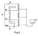
- Figure 2 shows a housing of a switchgear with three inner compartments 30, 31, 32 which are applied with the sensor arrangement, so that in each compartement a disturbance or fault light arc can be detected very fast and generate the ultra fast earthing switch in each case.
- One compartment 30 contains the busbars, one compartment contains the vacuum circuit breakers 31, and one compartment contains the cables 32.
Landscapes
- Gas-Insulated Switchgears (AREA)
- Driving Mechanisms And Operating Circuits Of Arc-Extinguishing High-Tension Switches (AREA)
- Electronic Switches (AREA)
Description
- The invention concerns to a switchgear with switching device, driven by propellant chemical charge or fast acting switch, with means for current or fault current detection and optical sensor means for light arc or fault light arc detection, according to the preamble of
claim 1. - In the state of the art, medium voltage switchgears with propellant chemical charge drives are in use for very fast earthing switches.
- An example for that is disclosed in
EP 09011839.9 - Actuators for fast earthing switches has to be extremely fast, in order to prevent further damage caused by occuring light arc.
- The document "
FR 1 434 214 Aclaim 1. - It is an object of the invention to reduce reaction and ignition time in case of occuring light arc in medium voltage switchgear.
- The invention follows to this object in that the electrical circuit of an inductive current detection means is electrically connected in series with the light sensing switching path, and that this current signal directly ignites the propellant chemical charge.
- By this the disturbing current increase will consequently be folded as technical fact with the light detection of a disturbing light arc in a cumulative way.
- If both technical conditions occur, it gives signal of a disturbant light arc, which has to be eliminated as quick as possible by earthing.
- In the state of the art, both signals will be detected by separate sensors, and both sensor signals will be sampled in an electronic device. This causes in series reaction time slots, which have to be added, so that the final mechanical earthing movement will be delayed.
- With the invention, a limited electronic device for generating a signal to ignite the drive will be used between the current transformer and the light sensor. Instead of that, a sensor with an inductive coupling to the main current path of the power path, generates a current in a circuit, which will be connected in series with the light arc sensor, in that way, that the light arc sensor becomes conductive in the moment of light exposure. So the inductive, by fault current induced current signal will flow over the momentary conductive light arc sensor and ignites directly the propellant charge. This without any additional electronic device with the need of auxiliaty voltage. So the drive will react very fast in case of occurring fault or disturbance current. To provide more power within the limited electronic device all three current transformer can be used to supply the energy inside these device to ignite the micro gas generator at the same time. This will be needed because the reaction time should be not selective for each phase. Only in case of the selective need the device can be driven per each phase.
- So it is an advantageous embodiment, that the switchgear is or contains a ultra fast earthing switch or a fast reacting switch.
- Furthermore easy to realize is, that a current limiting element (limited electronic device) is applied between the coupling inductivity and the light sensing switch.
- A further advantageous embodiment is, that the light sensing element is a photoresistor or a photocell.
- An alternative but also advantageous embodiment is, that the photoresistor or photocell is in functional connection with a microswitch, or a relay (or semiconductor relay with very short switching time in the range of 1ms for a microswitch and below 50µs for the semiconductor relay).
- Furthermore an advantageous embodiment of the invention is, that in case of the use of a switchgear housing with several separated and not separated compartments the arrangement of the electrical circuit of an inductive current detection means and its electrically in series connected light sensing switching path, is arranged in each compartment.
- A furthermore advantageous embodiment is, that the limited electronic device will connected to one current transformer for generating electrical power for igniting one micro gas generators or fast acting switch at the same time getting selectivity for each phase.
- A furthermore advantageous embodiment is, that the limited electronic device will connected to all three current transformer phases for generating electrical power for igniting all the three micro gas generators or fast acting switch at the same time.
-
Figure 1 shows the maincurrent path 10 of the switchgear. So the a.m. sensor arrangement is concluded in the components shown in the above part offigure 1 . Theinductive sensor element 11 detects a disturbing current (threathold value caused by the occurance of an internal arc) and reacts by induction of a current sensor in thesensor arrangement 1. A diode will limit this induced sensor current as logic threshold element. This is electrically in series with alight sensor 13. Also in series is themicro gas generator 14 with the propellant charge or with the fast reaction switch. The propellant charge will move the drive of an ultrafast earthing switch. - The part in the middle of
figure 1 shows the use of arelay 20 which switches a circuit in series with thelight sensor 13. The other components are the same as in the part above. - The last part of
figure 1 shows an embodiment, with a separate DC/AC source. The principle is the same. -
Figure 2 shows a housing of a switchgear with threeinner compartments - In the housing are arranged several compartments. One
compartment 30 contains the busbars, one compartment contains thevacuum circuit breakers 31, and one compartment contains thecables 32. -
- 1
- sensor arrangement with propellant charge
- 10
- main circuit path
- 11
- inductive sensor element
- 12
- limiting diode
- 13
- light sensor
- 14
- micro gas generator
- 20
- relay
- 30
- compartement
- 31
- vacuum circuit breaker
- 32
- cable
- 40
- ultra fast earthing switch
Claims (9)
- Switchgear with switching device, driven by propellant chemical charge (14) or fast acting switch, with means for current or fault current detection and optical sensor means (13) for light arc or fault light arc detection,
characterized in that it comprises an inductive current detector means and in that the electrical circuit of the inductive current detection means (11) is electrically connected in series with the light sensing switching path (13), and that this current signal directly ignites the propellant chemical charge (14). - Switchgear according to claim 1,
characterized in
that the switchgear is or contains a ultra fast earthing switch (40). - Switchgear according to claim 1,
characterized in
that the switchgear is or contains a fast reacting switch (40). - Switchgear according to claim 1 or 2,
characterized in
that a current limiting element (12) is applied between the coupling inductivity (11) and the light sensing switch (13) by applying a limited electronic device (12) without the need of auxiliary voltage. - Switchgear according to claim 1 or 2,
characterized in
that the light sensing element (13) is a photoresistor or a photocell. - Switchgear according to claim 5,
characterized in
that the photoresistor or photocell is in functional connection with a microswitch (20), or a relay (20) or a semiconductor relay (20). - Switchgear according to one of the aforesaid claims,
characterized in
that in case of the use of a switchgear housing with several separated and not separated compartments the arrangement of the electrical circuit of an inductive current detection means (11) and its electrically in series connected light sensing switching path (13) is arranged in each compartment. - Switchgear according to claim 4,
characterized in
that the limited electronic device will connected to one current transformer for generating electrical power for igniting one micro gas generators (14) or fast acting switch at the same time getting selectivity for each phase. - Switchgear according to claim 4,
characterized in
that the limited electronic device will connected to all three current transformer phases for generating electrical power for igniting all the three micro gas generators (14) or fast acting switch at the same time.
Priority Applications (4)
| Application Number | Priority Date | Filing Date | Title |
|---|---|---|---|
| EP12000638.2A EP2624272B1 (en) | 2012-02-01 | 2012-02-01 | Switchgear with switching device driven by propellant charge |
| US13/757,586 US9184004B2 (en) | 2012-02-01 | 2013-02-01 | Switchgear with switching device driven by propellant charge |
| BRBR102013002523-2A BR102013002523A2 (en) | 2012-02-01 | 2013-02-01 | BULK CHARGER SWITCHING CIRCUIT BREAKER |
| CN201310079985.7A CN103247474B (en) | 2012-02-01 | 2013-02-01 | Switching device with the switching device driven by propellant charges |
Applications Claiming Priority (1)
| Application Number | Priority Date | Filing Date | Title |
|---|---|---|---|
| EP12000638.2A EP2624272B1 (en) | 2012-02-01 | 2012-02-01 | Switchgear with switching device driven by propellant charge |
Publications (2)
| Publication Number | Publication Date |
|---|---|
| EP2624272A1 EP2624272A1 (en) | 2013-08-07 |
| EP2624272B1 true EP2624272B1 (en) | 2014-11-26 |
Family
ID=45592172
Family Applications (1)
| Application Number | Title | Priority Date | Filing Date |
|---|---|---|---|
| EP12000638.2A Not-in-force EP2624272B1 (en) | 2012-02-01 | 2012-02-01 | Switchgear with switching device driven by propellant charge |
Country Status (4)
| Country | Link |
|---|---|
| US (1) | US9184004B2 (en) |
| EP (1) | EP2624272B1 (en) |
| CN (1) | CN103247474B (en) |
| BR (1) | BR102013002523A2 (en) |
Cited By (1)
| Publication number | Priority date | Publication date | Assignee | Title |
|---|---|---|---|---|
| EP4089866A1 (en) | 2021-05-14 | 2022-11-16 | ABB Schweiz AG | Arc mitigation self-powered trigger device for low -, medium -, or high- voltage equipment |
Families Citing this family (6)
| Publication number | Priority date | Publication date | Assignee | Title |
|---|---|---|---|---|
| MX2016007622A (en) * | 2014-02-07 | 2017-02-17 | Philips Lighting Holding Bv | Safe operation of an led lamp. |
| WO2016031327A1 (en) * | 2014-08-28 | 2016-03-03 | 三菱電機株式会社 | High-speed contact device and switchgear equipped with same |
| DE102017208851B4 (en) | 2017-05-24 | 2019-03-07 | Siemens Aktiengesellschaft | Störlichtbogenerkennungseinheit |
| DE102018216210A1 (en) | 2018-09-24 | 2020-03-26 | Siemens Aktiengesellschaft | Quick-release latch, release mechanism and quick earth electrode, quick switch or short-circuiter |
| GB202018480D0 (en) | 2020-11-24 | 2021-01-06 | Gridon Ltd | Fault current limiter-divrter (fcld) |
| CN222672904U (en) * | 2024-05-10 | 2025-03-25 | 华为数字能源技术有限公司 | Switchgear and power systems |
Family Cites Families (8)
| Publication number | Priority date | Publication date | Assignee | Title |
|---|---|---|---|---|
| FR1434214A (en) * | 1965-01-16 | 1966-04-08 | Electricite De France | Improvements to synthetic circuit breaker testing stations |
| US4234901A (en) * | 1979-03-08 | 1980-11-18 | Westinghouse Electric Corp. | Protective relay apparatus |
| US4672174A (en) * | 1986-03-25 | 1987-06-09 | Usm Corporation | Monitoring stud-welding-phototransistor responds to arc light |
| US6198611B1 (en) * | 1998-12-15 | 2001-03-06 | Pass & Seymour, Inc. | Arc fault circuit interrupter without DC supply |
| US6657150B1 (en) * | 2002-06-14 | 2003-12-02 | Eaton Corporation | Shorting switch and system to eliminate arcing faults in power distribution equipment |
| GB2395377B (en) * | 2002-11-13 | 2006-02-01 | Frdx Ltd | Fault detection apparatus and method |
| DE102007022401A1 (en) * | 2007-05-10 | 2008-11-13 | Moeller Gmbh | Circuit breaker for arc fault protection |
| EP2299466B1 (en) * | 2009-09-17 | 2017-08-30 | ABB Schweiz AG | Fuze- or ignition cable with chemical charge material for the use in switching devices |
-
2012
- 2012-02-01 EP EP12000638.2A patent/EP2624272B1/en not_active Not-in-force
-
2013
- 2013-02-01 CN CN201310079985.7A patent/CN103247474B/en not_active Expired - Fee Related
- 2013-02-01 US US13/757,586 patent/US9184004B2/en active Active
- 2013-02-01 BR BRBR102013002523-2A patent/BR102013002523A2/en not_active Application Discontinuation
Cited By (2)
| Publication number | Priority date | Publication date | Assignee | Title |
|---|---|---|---|---|
| EP4089866A1 (en) | 2021-05-14 | 2022-11-16 | ABB Schweiz AG | Arc mitigation self-powered trigger device for low -, medium -, or high- voltage equipment |
| WO2022238322A1 (en) | 2021-05-14 | 2022-11-17 | Abb Schweiz Ag | Arc mitigation self-powered trigger device for low -, medium -, or high- voltage equipment |
Also Published As
| Publication number | Publication date |
|---|---|
| BR102013002523A2 (en) | 2014-09-09 |
| US9184004B2 (en) | 2015-11-10 |
| EP2624272A1 (en) | 2013-08-07 |
| US20130194707A1 (en) | 2013-08-01 |
| CN103247474B (en) | 2017-08-15 |
| CN103247474A (en) | 2013-08-14 |
Similar Documents
| Publication | Publication Date | Title |
|---|---|---|
| EP2624272A1 (en) | Switchgear with switching device driven by propellant charge | |
| RU2474906C2 (en) | Medium-voltage switchgear with short-circuit system | |
| AU2011231921B2 (en) | Switchgear assembly for medium voltage having a short-circuit unit | |
| US7619869B2 (en) | Electrical circuit breaker | |
| EP2186107B1 (en) | Circuit breaker with high speed mechanically-interlocked grounding switch | |
| CN101454859A (en) | Method for extinguishing an interference arc in a mid- and high-tension switchgear assembly and short circuit device itself | |
| EP2159813B1 (en) | A low-voltage, medium-voltage or high-voltage assembly | |
| JP5490136B2 (en) | Switching device for medium and high voltage switching elements | |
| EP2347485A1 (en) | Switching installation with arc protection and arc protection method | |
| CN202260228U (en) | Gas-insulated high-voltage switchgear | |
| CN202217960U (en) | High voltage switchgear | |
| US20150214715A1 (en) | Residual current protection device and electrical protection configuration for external actuation of an electromagnetic release | |
| US4032988A (en) | Compressed gas filled circuit breaker | |
| WO2024235787A1 (en) | Circuit breaker system with reduced own time: fault protection | |
| RU77503U1 (en) | THREE PHASE EXPLOSIVE FUSE | |
| EP2299466B1 (en) | Fuze- or ignition cable with chemical charge material for the use in switching devices | |
| EP4462620A1 (en) | Fault arc protection: circuit breaker system to interrupt faulty section | |
| Gentsch et al. | Solar-cell as trigger element for Ultra–Fast–Earthing Switch (UFES) for low–/medium-voltage; Self–powered | |
| KR200465381Y1 (en) | Ring main unit | |
| SU1372459A1 (en) | Arrangement for protecting buses from shorting arc currents | |
| CN118380818A (en) | Connectors, motor control systems, electric drive assemblies and vehicles | |
| SU650143A2 (en) | Unized distributing device cabinet | |
| EP2737584B1 (en) | Switching installation with pressure controlled short-circuit device | |
| RU77504U1 (en) | THREE PHASE EXPLOSIVE SWITCH |
Legal Events
| Date | Code | Title | Description |
|---|---|---|---|
| PUAI | Public reference made under article 153(3) epc to a published international application that has entered the european phase |
Free format text: ORIGINAL CODE: 0009012 |
|
| AK | Designated contracting states |
Kind code of ref document: A1 Designated state(s): AL AT BE BG CH CY CZ DE DK EE ES FI FR GB GR HR HU IE IS IT LI LT LU LV MC MK MT NL NO PL PT RO RS SE SI SK SM TR |
|
| AX | Request for extension of the european patent |
Extension state: BA ME |
|
| 17P | Request for examination filed |
Effective date: 20140207 |
|
| RBV | Designated contracting states (corrected) |
Designated state(s): AL AT BE BG CH CY CZ DE DK EE ES FI FR GB GR HR HU IE IS IT LI LT LU LV MC MK MT NL NO PL PT RO RS SE SI SK SM TR |
|
| GRAP | Despatch of communication of intention to grant a patent |
Free format text: ORIGINAL CODE: EPIDOSNIGR1 |
|
| RIC1 | Information provided on ipc code assigned before grant |
Ipc: H01H 9/54 20060101AFI20140520BHEP Ipc: H01H 39/00 20060101ALI20140520BHEP |
|
| INTG | Intention to grant announced |
Effective date: 20140618 |
|
| GRAS | Grant fee paid |
Free format text: ORIGINAL CODE: EPIDOSNIGR3 |
|
| GRAA | (expected) grant |
Free format text: ORIGINAL CODE: 0009210 |
|
| AK | Designated contracting states |
Kind code of ref document: B1 Designated state(s): AL AT BE BG CH CY CZ DE DK EE ES FI FR GB GR HR HU IE IS IT LI LT LU LV MC MK MT NL NO PL PT RO RS SE SI SK SM TR |
|
| REG | Reference to a national code |
Ref country code: GB Ref legal event code: FG4D |
|
| REG | Reference to a national code |
Ref country code: CH Ref legal event code: EP |
|
| REG | Reference to a national code |
Ref country code: AT Ref legal event code: REF Ref document number: 698605 Country of ref document: AT Kind code of ref document: T Effective date: 20141215 |
|
| REG | Reference to a national code |
Ref country code: IE Ref legal event code: FG4D |
|
| REG | Reference to a national code |
Ref country code: DE Ref legal event code: R096 Ref document number: 602012003915 Country of ref document: DE Effective date: 20150108 |
|
| REG | Reference to a national code |
Ref country code: NL Ref legal event code: VDEP Effective date: 20141126 |
|
| REG | Reference to a national code |
Ref country code: AT Ref legal event code: MK05 Ref document number: 698605 Country of ref document: AT Kind code of ref document: T Effective date: 20141126 |
|
| REG | Reference to a national code |
Ref country code: LT Ref legal event code: MG4D |
|
| PG25 | Lapsed in a contracting state [announced via postgrant information from national office to epo] |
Ref country code: NO Free format text: LAPSE BECAUSE OF FAILURE TO SUBMIT A TRANSLATION OF THE DESCRIPTION OR TO PAY THE FEE WITHIN THE PRESCRIBED TIME-LIMIT Effective date: 20150226 Ref country code: FI Free format text: LAPSE BECAUSE OF FAILURE TO SUBMIT A TRANSLATION OF THE DESCRIPTION OR TO PAY THE FEE WITHIN THE PRESCRIBED TIME-LIMIT Effective date: 20141126 Ref country code: NL Free format text: LAPSE BECAUSE OF FAILURE TO SUBMIT A TRANSLATION OF THE DESCRIPTION OR TO PAY THE FEE WITHIN THE PRESCRIBED TIME-LIMIT Effective date: 20141126 Ref country code: LT Free format text: LAPSE BECAUSE OF FAILURE TO SUBMIT A TRANSLATION OF THE DESCRIPTION OR TO PAY THE FEE WITHIN THE PRESCRIBED TIME-LIMIT Effective date: 20141126 Ref country code: ES Free format text: LAPSE BECAUSE OF FAILURE TO SUBMIT A TRANSLATION OF THE DESCRIPTION OR TO PAY THE FEE WITHIN THE PRESCRIBED TIME-LIMIT Effective date: 20141126 Ref country code: PT Free format text: LAPSE BECAUSE OF FAILURE TO SUBMIT A TRANSLATION OF THE DESCRIPTION OR TO PAY THE FEE WITHIN THE PRESCRIBED TIME-LIMIT Effective date: 20150326 Ref country code: IS Free format text: LAPSE BECAUSE OF FAILURE TO SUBMIT A TRANSLATION OF THE DESCRIPTION OR TO PAY THE FEE WITHIN THE PRESCRIBED TIME-LIMIT Effective date: 20150326 |
|
| PG25 | Lapsed in a contracting state [announced via postgrant information from national office to epo] |
Ref country code: RS Free format text: LAPSE BECAUSE OF FAILURE TO SUBMIT A TRANSLATION OF THE DESCRIPTION OR TO PAY THE FEE WITHIN THE PRESCRIBED TIME-LIMIT Effective date: 20141126 Ref country code: LV Free format text: LAPSE BECAUSE OF FAILURE TO SUBMIT A TRANSLATION OF THE DESCRIPTION OR TO PAY THE FEE WITHIN THE PRESCRIBED TIME-LIMIT Effective date: 20141126 Ref country code: GR Free format text: LAPSE BECAUSE OF FAILURE TO SUBMIT A TRANSLATION OF THE DESCRIPTION OR TO PAY THE FEE WITHIN THE PRESCRIBED TIME-LIMIT Effective date: 20150227 Ref country code: CY Free format text: LAPSE BECAUSE OF FAILURE TO SUBMIT A TRANSLATION OF THE DESCRIPTION OR TO PAY THE FEE WITHIN THE PRESCRIBED TIME-LIMIT Effective date: 20141126 Ref country code: SE Free format text: LAPSE BECAUSE OF FAILURE TO SUBMIT A TRANSLATION OF THE DESCRIPTION OR TO PAY THE FEE WITHIN THE PRESCRIBED TIME-LIMIT Effective date: 20141126 Ref country code: AT Free format text: LAPSE BECAUSE OF FAILURE TO SUBMIT A TRANSLATION OF THE DESCRIPTION OR TO PAY THE FEE WITHIN THE PRESCRIBED TIME-LIMIT Effective date: 20141126 Ref country code: HR Free format text: LAPSE BECAUSE OF FAILURE TO SUBMIT A TRANSLATION OF THE DESCRIPTION OR TO PAY THE FEE WITHIN THE PRESCRIBED TIME-LIMIT Effective date: 20141126 |
|
| PG25 | Lapsed in a contracting state [announced via postgrant information from national office to epo] |
Ref country code: SK Free format text: LAPSE BECAUSE OF FAILURE TO SUBMIT A TRANSLATION OF THE DESCRIPTION OR TO PAY THE FEE WITHIN THE PRESCRIBED TIME-LIMIT Effective date: 20141126 Ref country code: EE Free format text: LAPSE BECAUSE OF FAILURE TO SUBMIT A TRANSLATION OF THE DESCRIPTION OR TO PAY THE FEE WITHIN THE PRESCRIBED TIME-LIMIT Effective date: 20141126 Ref country code: RO Free format text: LAPSE BECAUSE OF FAILURE TO SUBMIT A TRANSLATION OF THE DESCRIPTION OR TO PAY THE FEE WITHIN THE PRESCRIBED TIME-LIMIT Effective date: 20141126 Ref country code: DK Free format text: LAPSE BECAUSE OF FAILURE TO SUBMIT A TRANSLATION OF THE DESCRIPTION OR TO PAY THE FEE WITHIN THE PRESCRIBED TIME-LIMIT Effective date: 20141126 |
|
| REG | Reference to a national code |
Ref country code: DE Ref legal event code: R097 Ref document number: 602012003915 Country of ref document: DE |
|
| PG25 | Lapsed in a contracting state [announced via postgrant information from national office to epo] |
Ref country code: PL Free format text: LAPSE BECAUSE OF FAILURE TO SUBMIT A TRANSLATION OF THE DESCRIPTION OR TO PAY THE FEE WITHIN THE PRESCRIBED TIME-LIMIT Effective date: 20141126 |
|
| PG25 | Lapsed in a contracting state [announced via postgrant information from national office to epo] |
Ref country code: LU Free format text: LAPSE BECAUSE OF FAILURE TO SUBMIT A TRANSLATION OF THE DESCRIPTION OR TO PAY THE FEE WITHIN THE PRESCRIBED TIME-LIMIT Effective date: 20150201 |
|
| REG | Reference to a national code |
Ref country code: CH Ref legal event code: PL |
|
| PLBE | No opposition filed within time limit |
Free format text: ORIGINAL CODE: 0009261 |
|
| STAA | Information on the status of an ep patent application or granted ep patent |
Free format text: STATUS: NO OPPOSITION FILED WITHIN TIME LIMIT |
|
| PG25 | Lapsed in a contracting state [announced via postgrant information from national office to epo] |
Ref country code: MC Free format text: LAPSE BECAUSE OF FAILURE TO SUBMIT A TRANSLATION OF THE DESCRIPTION OR TO PAY THE FEE WITHIN THE PRESCRIBED TIME-LIMIT Effective date: 20141126 Ref country code: LI Free format text: LAPSE BECAUSE OF NON-PAYMENT OF DUE FEES Effective date: 20150228 Ref country code: CH Free format text: LAPSE BECAUSE OF NON-PAYMENT OF DUE FEES Effective date: 20150228 |
|
| 26N | No opposition filed |
Effective date: 20150827 |
|
| REG | Reference to a national code |
Ref country code: IE Ref legal event code: MM4A |
|
| PG25 | Lapsed in a contracting state [announced via postgrant information from national office to epo] |
Ref country code: IE Free format text: LAPSE BECAUSE OF NON-PAYMENT OF DUE FEES Effective date: 20150201 |
|
| REG | Reference to a national code |
Ref country code: FR Ref legal event code: PLFP Year of fee payment: 5 |
|
| PG25 | Lapsed in a contracting state [announced via postgrant information from national office to epo] |
Ref country code: SI Free format text: LAPSE BECAUSE OF FAILURE TO SUBMIT A TRANSLATION OF THE DESCRIPTION OR TO PAY THE FEE WITHIN THE PRESCRIBED TIME-LIMIT Effective date: 20141126 |
|
| PGFP | Annual fee paid to national office [announced via postgrant information from national office to epo] |
Ref country code: GB Payment date: 20160217 Year of fee payment: 5 |
|
| REG | Reference to a national code |
Ref country code: DE Ref legal event code: R082 Ref document number: 602012003915 Country of ref document: DE Representative=s name: ABB PATENT GMBH, DE Ref country code: DE Ref legal event code: R081 Ref document number: 602012003915 Country of ref document: DE Owner name: ABB SCHWEIZ AG, CH Free format text: FORMER OWNER: ABB TECHNOLOGY AG, ZUERICH, CH |
|
| PG25 | Lapsed in a contracting state [announced via postgrant information from national office to epo] |
Ref country code: MT Free format text: LAPSE BECAUSE OF FAILURE TO SUBMIT A TRANSLATION OF THE DESCRIPTION OR TO PAY THE FEE WITHIN THE PRESCRIBED TIME-LIMIT Effective date: 20141126 |
|
| REG | Reference to a national code |
Ref country code: FR Ref legal event code: PLFP Year of fee payment: 6 |
|
| PG25 | Lapsed in a contracting state [announced via postgrant information from national office to epo] |
Ref country code: HU Free format text: LAPSE BECAUSE OF FAILURE TO SUBMIT A TRANSLATION OF THE DESCRIPTION OR TO PAY THE FEE WITHIN THE PRESCRIBED TIME-LIMIT; INVALID AB INITIO Effective date: 20120201 Ref country code: SM Free format text: LAPSE BECAUSE OF FAILURE TO SUBMIT A TRANSLATION OF THE DESCRIPTION OR TO PAY THE FEE WITHIN THE PRESCRIBED TIME-LIMIT Effective date: 20141126 Ref country code: BG Free format text: LAPSE BECAUSE OF FAILURE TO SUBMIT A TRANSLATION OF THE DESCRIPTION OR TO PAY THE FEE WITHIN THE PRESCRIBED TIME-LIMIT Effective date: 20141126 |
|
| PG25 | Lapsed in a contracting state [announced via postgrant information from national office to epo] |
Ref country code: TR Free format text: LAPSE BECAUSE OF FAILURE TO SUBMIT A TRANSLATION OF THE DESCRIPTION OR TO PAY THE FEE WITHIN THE PRESCRIBED TIME-LIMIT Effective date: 20141126 |
|
| PG25 | Lapsed in a contracting state [announced via postgrant information from national office to epo] |
Ref country code: BE Free format text: LAPSE BECAUSE OF FAILURE TO SUBMIT A TRANSLATION OF THE DESCRIPTION OR TO PAY THE FEE WITHIN THE PRESCRIBED TIME-LIMIT Effective date: 20141126 |
|
| GBPC | Gb: european patent ceased through non-payment of renewal fee |
Effective date: 20170201 |
|
| REG | Reference to a national code |
Ref country code: FR Ref legal event code: PLFP Year of fee payment: 7 |
|
| PG25 | Lapsed in a contracting state [announced via postgrant information from national office to epo] |
Ref country code: GB Free format text: LAPSE BECAUSE OF NON-PAYMENT OF DUE FEES Effective date: 20170201 |
|
| PG25 | Lapsed in a contracting state [announced via postgrant information from national office to epo] |
Ref country code: MK Free format text: LAPSE BECAUSE OF FAILURE TO SUBMIT A TRANSLATION OF THE DESCRIPTION OR TO PAY THE FEE WITHIN THE PRESCRIBED TIME-LIMIT Effective date: 20141126 |
|
| REG | Reference to a national code |
Ref country code: FR Ref legal event code: TP Owner name: ABB SCHWEIZ AG, CH Effective date: 20180912 |
|
| PG25 | Lapsed in a contracting state [announced via postgrant information from national office to epo] |
Ref country code: AL Free format text: LAPSE BECAUSE OF FAILURE TO SUBMIT A TRANSLATION OF THE DESCRIPTION OR TO PAY THE FEE WITHIN THE PRESCRIBED TIME-LIMIT Effective date: 20141126 |
|
| PGFP | Annual fee paid to national office [announced via postgrant information from national office to epo] |
Ref country code: IT Payment date: 20190225 Year of fee payment: 8 Ref country code: CZ Payment date: 20190130 Year of fee payment: 8 |
|
| PG25 | Lapsed in a contracting state [announced via postgrant information from national office to epo] |
Ref country code: CZ Free format text: LAPSE BECAUSE OF NON-PAYMENT OF DUE FEES Effective date: 20200201 |
|
| PG25 | Lapsed in a contracting state [announced via postgrant information from national office to epo] |
Ref country code: IT Free format text: LAPSE BECAUSE OF NON-PAYMENT OF DUE FEES Effective date: 20200201 |
|
| PGFP | Annual fee paid to national office [announced via postgrant information from national office to epo] |
Ref country code: DE Payment date: 20240219 Year of fee payment: 13 |
|
| PGFP | Annual fee paid to national office [announced via postgrant information from national office to epo] |
Ref country code: FR Payment date: 20240221 Year of fee payment: 13 |
|
| REG | Reference to a national code |
Ref country code: DE Ref legal event code: R119 Ref document number: 602012003915 Country of ref document: DE |
|
| PG25 | Lapsed in a contracting state [announced via postgrant information from national office to epo] |
Ref country code: DE Free format text: LAPSE BECAUSE OF NON-PAYMENT OF DUE FEES Effective date: 20250902 |
|
| PG25 | Lapsed in a contracting state [announced via postgrant information from national office to epo] |
Ref country code: FR Free format text: LAPSE BECAUSE OF NON-PAYMENT OF DUE FEES Effective date: 20250228 |