EP2624080A2 - System and method to performance tune a system - Google Patents
System and method to performance tune a system Download PDFInfo
- Publication number
- EP2624080A2 EP2624080A2 EP13153382.0A EP13153382A EP2624080A2 EP 2624080 A2 EP2624080 A2 EP 2624080A2 EP 13153382 A EP13153382 A EP 13153382A EP 2624080 A2 EP2624080 A2 EP 2624080A2
- Authority
- EP
- European Patent Office
- Prior art keywords
- performance
- site
- controllers
- subsystems
- parameters
- Prior art date
- Legal status (The legal status is an assumption and is not a legal conclusion. Google has not performed a legal analysis and makes no representation as to the accuracy of the status listed.)
- Granted
Links
Images

Classifications
-
- G—PHYSICS
- G05—CONTROLLING; REGULATING
- G05B—CONTROL OR REGULATING SYSTEMS IN GENERAL; FUNCTIONAL ELEMENTS OF SUCH SYSTEMS; MONITORING OR TESTING ARRANGEMENTS FOR SUCH SYSTEMS OR ELEMENTS
- G05B13/00—Adaptive control systems, i.e. systems automatically adjusting themselves to have a performance which is optimum according to some preassigned criterion
- G05B13/02—Adaptive control systems, i.e. systems automatically adjusting themselves to have a performance which is optimum according to some preassigned criterion electric
- G05B13/04—Adaptive control systems, i.e. systems automatically adjusting themselves to have a performance which is optimum according to some preassigned criterion electric involving the use of models or simulators
-
- Y—GENERAL TAGGING OF NEW TECHNOLOGICAL DEVELOPMENTS; GENERAL TAGGING OF CROSS-SECTIONAL TECHNOLOGIES SPANNING OVER SEVERAL SECTIONS OF THE IPC; TECHNICAL SUBJECTS COVERED BY FORMER USPC CROSS-REFERENCE ART COLLECTIONS [XRACs] AND DIGESTS
- Y02—TECHNOLOGIES OR APPLICATIONS FOR MITIGATION OR ADAPTATION AGAINST CLIMATE CHANGE
- Y02E—REDUCTION OF GREENHOUSE GAS [GHG] EMISSIONS, RELATED TO ENERGY GENERATION, TRANSMISSION OR DISTRIBUTION
- Y02E20/00—Combustion technologies with mitigation potential
- Y02E20/16—Combined cycle power plant [CCPP], or combined cycle gas turbine [CCGT]
Definitions
- the subject matter disclosed herein relates to a command controller in a control system to obtain target performance.
- each subsystem in a combined cycle power plant, which includes a gas turbine and a steam turbine driven by the heat generated by the gas turbine, for example, each subsystem (gas turbine, steam turbine, etc.) includes a controller to adjust parameters to achieve a given target performance for that subsystem.
- the overall system performance is considered, such as to determine if the system is achieving quoted performance levels, for example, human intervention has been necessary to determine which subsystems should be adjusted and what target performance each of those subsystems should achieve.
- a command controller to determine the target for each subsystem in order to achieve an overall system target performance without human intervention would be appreciated in the art.
- a control system includes one or more controllers, each of the one or more controllers being configured to control a respective one of one or more subsystems of a site system by changing values of a respective set of parameters; a site reference model configured to indicate a target performance of the site system; and a processor configured to instruct the one or more controllers based on the target performance for the site system.
- a method of performance tuning a site system includes determining a target performance for the site system; determining a gap between the target performance and a real performance of the site system; and instructing one or more controllers, each of the one or more controllers controlling a respective one of one or more subsystems of the site system, each instruction instructing a controller to obtain a target subsystem performance for a corresponding subsystem by changing one or more parameters of the subsystem.
- a system to performance tune a combined cycle power plant includes one or more controllers, each of the one or more controllers being configured to control a respective one of one or more subsystems of the combined cycle power plant by changing values of a respective set of parameters; a site reference model configured to indicate a target performance of the combined cycle power plant; and a processor configured to determine a performance gap for the combined cycle power plant based on the site reference model, to determine a target subsystem performance for each of the one or more subsystems based on a priority and a tolerance of each parameter in the respective set of parameters of the one or more subsystems, and to instruct the one or more controllers based on the target subsystem performance.
- Embodiments of the present invention are described with specific reference to a combined cycle power plant. However, it should be understood that the various embodiments are not limited to the example system and are applicable to any system with one or more subsystems that can be controlled to attain a target performance.
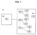
- FIG. 1 is a block diagram of a control system 10 according to an embodiment of the invention.
- the control system 10 includes a command controller 100 to control a combined cycle system 110.
- the command controller 100 may be temporarily or permanently co-located with the combined cycle system 110 or may operate remotely.
- the command controller 100 includes or, in an alternate embodiment, is in communication with a site reference model 105, and the combined cycle system 110 includes a site specific model 115.
- the site reference model 105 approximates the operation of the real combined cycle system 110.
- the site reference model 105 may have been used, for example, to determine the quoted performance values for the combined cycle system 110 prior to its installation on-site.
- the site specific model 115 is maintained to reflect the real operation of the combined cycle system 110.
- the site reference model 105 can be regarded as indicating the ideal performance of the combined cycle system 110 according to its design, while the site specific model 115 can be regarded as indicating the actual performance of the combined cycle system 110.
- the two models 105, 115 would indicate the same performance output for the combined cycle system 110.
- the performance indicated by the site specific model 115 may differ from (be degraded from) the performance indicated by the site reference model 105.
- the combined cycle system 110 includes various parameters 130 controlled by a plurality of controllers 120. Control within the combined cycle system 110 is comprised of a set of controllers 120 each controlling parameters 130 associated with a certain subsystem.
- parameters 130a through 130j controlled by controller 120a may be parameters 130 associated with the steam turbine subsystem of the combined cycle system 110.
- parameters 130m through 130s controlled by controller 120b may be parameters 130 associated with the heat recovery steam generator (HRSG) subsystem.
- HRSG heat recovery steam generator
- Some of the parameters 130 associated with the gas turbine subsystem include firing temperature of the gas turbine combustion system, inlet guide vane angle, variable stator vane angle, inlet bleed heat flow, and compressor extraction flow.
- the site reference model 105 may have been available and may have provided the quoted performance values for the combined cycle system 110.
- human intervention was needed to adequately control the parameters 130 of the combined cycle system 110 to achieve quoted performance values.
- the human intervention may have involved an analysis of the differences between the site reference model 105 and the real combined cycle system 110. A person would set targets for the controllers 120 based on the analysis in order to have the combined cycle system 110 performance approach or equal the quoted performance values (performance of the site reference model 105).
- the combined cycle system 110 is an example system with a plurality of controllers 120 for a plurality of subsystems that benefits from the command controller 100.
- any system for example a turbomachine with a single controller 120, also benefits from a command controller 100 according to an embodiment of the invention.
- the command controller 100 may be executed on the same processor as the controller 120.
- the command controller 100 determines a gap between the performance indicated by the site reference model 105 and the site specific model 115 and sets a target performance for the single controller 120, in the case of the turbomachine or another single-controller 120 system, to close the gap without the need for human intervention.
- the command controller 100 is able to analyze the site reference model 105 and the site specific model 115 to more readily ascertain the differences that lead to the real combined cycle system 110 not achieving the quoted performance values. Once the differences (gap in performance between real and quoted) are analyzed and understood by the command controller 100, the command controller 100 determines the necessary control needed from each of the controllers 120 to close the gap. In one embodiment, the command controller 100 performs a rule-based multi-dimensional optimization routine to determine a target for each controller 120 based on the priority (in what order should a given parameter 130 be changed) and tolerance (how much can a given parameter 130 be changed) associated with each parameter 130. That is, an algorithm solves for the lowest cost path to match site reference model 105 output to site specific model 115 output. Alternately, the command controller 100 could be a neural network that is trained to learn the costs over time.
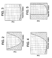
- FIGs. 2-5 illustrate example costs associated with changing parameters 130 according to an embodiment of the invention.
- a range of parameter 130 values is shown on the x (horizontal) axis and the cost associated with a parameter 130 value in the range is shown on the y (vertical) axis.
- the command controller 100 analyzes the costs in conjunction with priorities of the parameters 130 to affect changes in the combined cycle system 110 with little or, ideally, no cost.
- each parameter 130 is represented by a parabola that indicates the cost associated with changing that parameter 130.
- a given parameter 130 may have a high priority because controlling that parameter 130 affects the performance of the combined cycle system 110 substantially, but the tolerance (amount of change) for the parameter 130 may be low before a high cost is incurred.
- a parameter 130 may have a high tolerance such that the parameter 130 can be changed over a wide range without a significant change in cost. If such a parameter 130 also has a high priority (has a significant effect on overall combined cycle system 110 performance), then the parameter 130 is a good candidate for control by the command controller 100.
- FIG. 4 illustrates a situation in which a parameter 130 value may be decreased with little cost but leads to a high cost if its value is increased.
- FIG. 5 illustrates a situation in which a parameter 130 has limits within which it may be changed with low cost.
- the command controller 100 must balance the priority and tolerance of multiple parameters 130.
- the command controller 100 does not operate on any given parameter 130 itself but, instead, sets the targets for the individual controllers 120 based on the analysis of priority and tolerance (cost) of the various parameters 130 controlled by the various controllers 120.
- the command controller 100 and each of the controllers 120 may be comprised of one or more memory devices and one or more processors.
- the site reference model 105 is shown as part of the command controller 100 by FIG. 2 , but, in alternate embodiments, the site reference model 105 may be executed by a separate processor or set of processors along with one or more memory devices.
- the command controller 100 may be brought on-site to the combined cycle system 110 or remotely integrated with the combined cycle system 110 for periodic (e.g., seasonal) adjustments or may be permanently co-located with the combined cycle system 110 to continually adjust performance to compensate for degradation.
- FIG. 6 depicts processes included in the controlling the controllers 120 to performance tune the combined cycle system 110 according to an embodiment of the invention.
- determining target performance for the combined cycle system 110 involves a site reference model 105.
- the target performance may be quoted performance for the combined cycle system 110 that was provided before initiation of operation of the combined cycle system 110.
- determining a gap between the target performance and the real performance of the combined cycle system 110 may include using a site specific model 115 and analyzing differences between the site reference model 105 and the site specific model 115.
- analyzing priority and tolerance of parameters 130 of the subsystems controlled by the controllers 120 includes accessing stored information about each parameter 130. The information may be represented as shown by example FIGs. 2-5 .
- instructing the controllers 120 of the respective subsystems includes the command controller 100 instructing the controllers 120 to change parameter 130 values in accordance with the priority and tolerance analysis to achieve a specified target performance for each subsystem.
Landscapes
- Engineering & Computer Science (AREA)
- Health & Medical Sciences (AREA)
- Artificial Intelligence (AREA)
- Computer Vision & Pattern Recognition (AREA)
- Evolutionary Computation (AREA)
- Medical Informatics (AREA)
- Software Systems (AREA)
- Physics & Mathematics (AREA)
- General Physics & Mathematics (AREA)
- Automation & Control Theory (AREA)
- Feedback Control In General (AREA)
- Engine Equipment That Uses Special Cycles (AREA)
Abstract
Description
- The subject matter disclosed herein relates to a command controller in a control system to obtain target performance.
- In a combined cycle power plant, which includes a gas turbine and a steam turbine driven by the heat generated by the gas turbine, for example, each subsystem (gas turbine, steam turbine, etc.) includes a controller to adjust parameters to achieve a given target performance for that subsystem. When the overall system performance is considered, such as to determine if the system is achieving quoted performance levels, for example, human intervention has been necessary to determine which subsystems should be adjusted and what target performance each of those subsystems should achieve. A command controller to determine the target for each subsystem in order to achieve an overall system target performance without human intervention would be appreciated in the art.
- According to one aspect of the invention, a control system includes one or more controllers, each of the one or more controllers being configured to control a respective one of one or more subsystems of a site system by changing values of a respective set of parameters; a site reference model configured to indicate a target performance of the site system; and a processor configured to instruct the one or more controllers based on the target performance for the site system.
- According to another aspect of the invention, a method of performance tuning a site system includes determining a target performance for the site system; determining a gap between the target performance and a real performance of the site system; and instructing one or more controllers, each of the one or more controllers controlling a respective one of one or more subsystems of the site system, each instruction instructing a controller to obtain a target subsystem performance for a corresponding subsystem by changing one or more parameters of the subsystem.
- According to yet another aspect of the invention, a system to performance tune a combined cycle power plant includes one or more controllers, each of the one or more controllers being configured to control a respective one of one or more subsystems of the combined cycle power plant by changing values of a respective set of parameters; a site reference model configured to indicate a target performance of the combined cycle power plant; and a processor configured to determine a performance gap for the combined cycle power plant based on the site reference model, to determine a target subsystem performance for each of the one or more subsystems based on a priority and a tolerance of each parameter in the respective set of parameters of the one or more subsystems, and to instruct the one or more controllers based on the target subsystem performance.
- These and other advantages and features will become more apparent from the following description taken in conjunction with the drawings.
- The subject matter, which is regarded as the invention, is particularly pointed out and distinctly claimed in the claims at the conclusion of the specification. The foregoing and other features, and advantages of the invention are apparent from the following detailed description taken in conjunction with the accompanying drawings in which:
-
FIG. 1 is a block diagram of a control system according to an embodiment of the invention; -
FIGs. 2-5 illustrate example costs associated with changing parameters according to an embodiment of the invention; and -
FIG. 6 depicts processes included in the controlling the controllers to performance tune the combined cycle system according to an embodiment of the invention. - The detailed description explains embodiments of the invention, together with advantages and features, by way of example with reference to the drawings.
- Embodiments of the present invention are described with specific reference to a combined cycle power plant. However, it should be understood that the various embodiments are not limited to the example system and are applicable to any system with one or more subsystems that can be controlled to attain a target performance.
-
FIG. 1 is a block diagram of acontrol system 10 according to an embodiment of the invention. Thecontrol system 10 includes acommand controller 100 to control a combinedcycle system 110. Thecommand controller 100 may be temporarily or permanently co-located with the combinedcycle system 110 or may operate remotely. Thecommand controller 100 includes or, in an alternate embodiment, is in communication with asite reference model 105, and the combinedcycle system 110 includes a sitespecific model 115. Thesite reference model 105 approximates the operation of the real combinedcycle system 110. Thesite reference model 105 may have been used, for example, to determine the quoted performance values for the combinedcycle system 110 prior to its installation on-site. The sitespecific model 115 is maintained to reflect the real operation of the combinedcycle system 110. Thus, thesite reference model 105 can be regarded as indicating the ideal performance of the combinedcycle system 110 according to its design, while the sitespecific model 115 can be regarded as indicating the actual performance of the combinedcycle system 110. Ideally, the twomodels cycle system 110. However, because of mechanical tolerances in the actual combinedcycle system 110, the performance indicated by the sitespecific model 115 may differ from (be degraded from) the performance indicated by thesite reference model 105. Because some deviations in the real combinedcycle system 110 from the design of thesite reference model 105 cannot be corrected without a substantial effort (e.g., rotor replacement), those types of differences must, instead, be mitigated through the control of various parameters 130 of the combinedcycle system 110 in order to achieve the quoted performance output with the real combinedcycle system 110. - The combined
cycle system 110 includes various parameters 130 controlled by a plurality of controllers 120. Control within the combinedcycle system 110 is comprised of a set of controllers 120 each controlling parameters 130 associated with a certain subsystem. For example,parameters 130a through 130j controlled bycontroller 120a may be parameters 130 associated with the steam turbine subsystem of the combinedcycle system 110. As another example,parameters 130m through 130s controlled bycontroller 120b may be parameters 130 associated with the heat recovery steam generator (HRSG) subsystem. Some of the parameters 130 associated with the gas turbine subsystem, for example, include firing temperature of the gas turbine combustion system, inlet guide vane angle, variable stator vane angle, inlet bleed heat flow, and compressor extraction flow. In prior systems that did not benefit from thecommand controller 100 and sitespecific model 115, thesite reference model 105 may have been available and may have provided the quoted performance values for the combinedcycle system 110. In those prior systems, human intervention was needed to adequately control the parameters 130 of the combinedcycle system 110 to achieve quoted performance values. The human intervention may have involved an analysis of the differences between thesite reference model 105 and the real combinedcycle system 110. A person would set targets for the controllers 120 based on the analysis in order to have the combinedcycle system 110 performance approach or equal the quoted performance values (performance of the site reference model 105). - As noted above, the combined
cycle system 110 is an example system with a plurality of controllers 120 for a plurality of subsystems that benefits from thecommand controller 100. However, any system, for example a turbomachine with a single controller 120, also benefits from acommand controller 100 according to an embodiment of the invention. In the case of a single controller 120 system, thecommand controller 100 may be executed on the same processor as the controller 120. Thecommand controller 100 determines a gap between the performance indicated by thesite reference model 105 and the sitespecific model 115 and sets a target performance for the single controller 120, in the case of the turbomachine or another single-controller 120 system, to close the gap without the need for human intervention. - The
command controller 100 is able to analyze thesite reference model 105 and the sitespecific model 115 to more readily ascertain the differences that lead to the real combinedcycle system 110 not achieving the quoted performance values. Once the differences (gap in performance between real and quoted) are analyzed and understood by thecommand controller 100, thecommand controller 100 determines the necessary control needed from each of the controllers 120 to close the gap. In one embodiment, thecommand controller 100 performs a rule-based multi-dimensional optimization routine to determine a target for each controller 120 based on the priority (in what order should a given parameter 130 be changed) and tolerance (how much can a given parameter 130 be changed) associated with each parameter 130. That is, an algorithm solves for the lowest cost path to matchsite reference model 105 output to sitespecific model 115 output. Alternately, thecommand controller 100 could be a neural network that is trained to learn the costs over time. -
FIGs. 2-5 illustrate example costs associated with changing parameters 130 according to an embodiment of the invention. A range of parameter 130 values is shown on the x (horizontal) axis and the cost associated with a parameter 130 value in the range is shown on the y (vertical) axis. Thecommand controller 100 analyzes the costs in conjunction with priorities of the parameters 130 to affect changes in the combinedcycle system 110 with little or, ideally, no cost. As shown byFIGs. 2-5 , each parameter 130 is represented by a parabola that indicates the cost associated with changing that parameter 130. For example, a given parameter 130 may have a high priority because controlling that parameter 130 affects the performance of the combinedcycle system 110 substantially, but the tolerance (amount of change) for the parameter 130 may be low before a high cost is incurred. This situation is illustrated byFIG. 2 . In another example, illustrated byFIG. 3 , a parameter 130 may have a high tolerance such that the parameter 130 can be changed over a wide range without a significant change in cost. If such a parameter 130 also has a high priority (has a significant effect on overall combinedcycle system 110 performance), then the parameter 130 is a good candidate for control by thecommand controller 100.FIG. 4 illustrates a situation in which a parameter 130 value may be decreased with little cost but leads to a high cost if its value is increased.FIG. 5 illustrates a situation in which a parameter 130 has limits within which it may be changed with low cost. Ultimately, thecommand controller 100 must balance the priority and tolerance of multiple parameters 130. Unlike the controllers 120 that operate on one or more parameters 130 to reach a target performance set for a given subsystem, thecommand controller 100 does not operate on any given parameter 130 itself but, instead, sets the targets for the individual controllers 120 based on the analysis of priority and tolerance (cost) of the various parameters 130 controlled by the various controllers 120. - The
command controller 100 and each of the controllers 120 may be comprised of one or more memory devices and one or more processors. Thesite reference model 105 is shown as part of thecommand controller 100 byFIG. 2 , but, in alternate embodiments, thesite reference model 105 may be executed by a separate processor or set of processors along with one or more memory devices. Thecommand controller 100 may be brought on-site to the combinedcycle system 110 or remotely integrated with the combinedcycle system 110 for periodic (e.g., seasonal) adjustments or may be permanently co-located with the combinedcycle system 110 to continually adjust performance to compensate for degradation. -
FIG. 6 depicts processes included in the controlling the controllers 120 to performance tune the combinedcycle system 110 according to an embodiment of the invention. Atblock 610, determining target performance for the combinedcycle system 110 involves asite reference model 105. The target performance may be quoted performance for the combinedcycle system 110 that was provided before initiation of operation of the combinedcycle system 110. Atblock 620, determining a gap between the target performance and the real performance of the combinedcycle system 110 may include using a sitespecific model 115 and analyzing differences between thesite reference model 105 and the sitespecific model 115. At 630, analyzing priority and tolerance of parameters 130 of the subsystems controlled by the controllers 120 includes accessing stored information about each parameter 130. The information may be represented as shown by exampleFIGs. 2-5 . Once thecommand controller 100 analyzes the parameters 130 to determine the most efficient way to close the gap between real performance and target performance of the combinedcycle system 110, instructing the controllers 120 of the respective subsystems includes thecommand controller 100 instructing the controllers 120 to change parameter 130 values in accordance with the priority and tolerance analysis to achieve a specified target performance for each subsystem. - While the invention has been described in detail in connection with only a limited number of embodiments, it should be readily understood that the invention is not limited to such disclosed embodiments. Rather, the invention can be modified to incorporate any number of variations, alterations, substitutions or equivalent arrangements not heretofore described, but which are commensurate with the scope of the invention is defined in the appended claims. Additionally, while various embodiments of the invention have been described, it is to be understood that aspects of the invention may include only some of the described embodiments. Accordingly, the invention is not to be seen as limited by the foregoing description, but is only limited by the scope of the appended claims.
Claims (16)
- A system (10) to performance tune a site system (110), comprising:one or more controllers (120), each of the one or more controllers being configured to control a respective one of one or more subsystems of the site system by changing values of a respective set of parameters (130);a site reference model (105) configured to indicate a target performance of the site system; anda processor configured to instruct the one or more controllers based on the target performance for the site system.
- The system according to claim 1, further comprising a site specific model (115) configured to indicate an actual output of the site system (110), wherein the processor determines a difference between the site reference model and the site specific model to determine a performance gap of the site system.
- The system according to claim 2, further comprising:a memory device configured to store a priority and a tolerance associated with each parameter of the set of parameters (130) for each of the one or more subsystems of the site system, the priority of a parameter indicating an order in which to change the parameter and the tolerance of the parameter indicating an amount within which to change the parameter, whereinthe processor determines a target subsystem performance for each of the one or more subsystems and instructs the one or more controllers (120) to control the respective one or more subsystems based on the performance gap and the target subsystem performance according to an analysis of the priority and the tolerance of parameters of the one or more subsystems.
- The system according to any preceding claim, wherein the site system (110) is a combined cycle power plant, and the one or more subsystems include one or more of a gas turbine, a heat recovery steam generator (HRSG), and a steam turbine.
- The system according to any preceding claim, wherein the site system is a turbomachine, and preferably the parameters include one or more of a firing temperature of a gas turbine combustion system, an inlet guide vane angle, a variable stator vane angle, an inlet bleed heat flow, and a compressor extraction flow.
- A method of performance tuning a site system, the method comprising:determining (610) a target performance for the site system;determining (620) a gap between the target performance and a real performance of the site system; andinstructing (640) one or more controllers, each of the one or more controllers controlling a respective one of one or more subsystems of the site system, each instruction instructing a controller to obtain a target subsystem performance for a corresponding subsystem by changing one or more parameters of the subsystem.
- The method according to claim 6, wherein the determining (620) the gap includes analyzing a site reference model that provides the target performance of the site system and a site specific model that indicates actual performance of the site system.
- The method according to claim 6 or claim 7, further comprising analyzing (630) a priority and a tolerance of parameters of the one or more subsystems of the site system, wherein the instructing the one or more controllers includes indicating the target subsystem performance for the corresponding subsystem based on the analyzing.
- The method according to claim 6, 7 or 8 wherein the site system is a combined cycle power plant, and preferably the instructing (640) the one or more controllers includes instructing controllers of one or more of a gas turbine, a heat recovery steam generator (HRSG), and a steam turbine.
- The method according to claim 9, wherein the site system is a turbomachine and preferably the analyzing (630) the priority and the tolerance of parameters includes analyzing the priority and the tolerance of one or more of a firing temperature of a gas turbine combustion system, an inlet guide vane angle, a variable stator vane angle, an inlet bleed heat flow, and a compressor extraction flow.
- A system (10) to performance tune a combined cycle power plant (110), the system comprising:one or more controllers (120), each of the one or more controllers being configured to control a respective one of one or more subsystems of the combined cycle power plant by changing values of a respective set of parameters (130);a site reference model (105) configured to indicate a target performance of the combined cycle power plant; anda processor configured to determine a performance gap for the combined cycle power plant based on the site reference model, to determine a target subsystem performance for each of the one or more subsystems based on a priority and a tolerance of each parameter in the respective set of parameters (130) of the one or more subsystems, and to instruct the one or more controllers (120) based on the target subsystem performance.
- The system according to claim 11, further comprising a site specific model (115) configured to indicate actual performance of the combined cycle power plant, and wherein, preferably the processor is configured to determine the performance gap by determining a difference between the site reference model and the site specific model.
- The system according to claim 11 or claim 12, further comprising a memory device configured to store the priority and the tolerance associated with each parameter of the respective set of parameters of each of the one or more subsystems.
- The system according to claim 13, wherein the processor accesses the memory device and determines the target subsystem performance for each of the one or more subsystems and instructs the one or more controllers to minimize a cost of approaching the target performance of the combined cycle power plant.
- The system according to claim 14, wherein the cost is a function of the priority and the tolerance of each of the set of parameters.
- The system according to any one of claims 11 to 15, wherein the one or more subsystems include a gas turbine, a heat recovery steam generator (HRSG), and a steam turbine.
Applications Claiming Priority (1)
| Application Number | Priority Date | Filing Date | Title |
|---|---|---|---|
| US13/364,426 US9298173B2 (en) | 2012-02-02 | 2012-02-02 | System and method to performance tune a system |
Publications (3)
| Publication Number | Publication Date |
|---|---|
| EP2624080A2 true EP2624080A2 (en) | 2013-08-07 |
| EP2624080A3 EP2624080A3 (en) | 2015-03-04 |
| EP2624080B1 EP2624080B1 (en) | 2019-11-06 |
Family
ID=47747364
Family Applications (1)
| Application Number | Title | Priority Date | Filing Date |
|---|---|---|---|
| EP13153382.0A Active EP2624080B1 (en) | 2012-02-02 | 2013-01-31 | System and method to performance tune a system |
Country Status (3)
| Country | Link |
|---|---|
| US (1) | US9298173B2 (en) |
| EP (1) | EP2624080B1 (en) |
| JP (1) | JP6105952B2 (en) |
Family Cites Families (28)
| Publication number | Priority date | Publication date | Assignee | Title |
|---|---|---|---|---|
| US4249238A (en) * | 1978-05-24 | 1981-02-03 | The United States Of America As Represented By The Administrator Of The National Aeronautics And Space Administration | Apparatus for sensor failure detection and correction in a gas turbine engine control system |
| US4534216A (en) * | 1983-05-31 | 1985-08-13 | United Technologies Corporation | Method and apparatus for determining the accuracy of wind tunnel test data |
| US5005351A (en) * | 1990-02-26 | 1991-04-09 | Westinghouse Electric Corp. | Power plant condenser control system |
| US5423272A (en) | 1994-04-11 | 1995-06-13 | Combustion Engineering, Inc. | Method for optimizing the operating efficiency of a fossil fuel-fired power generation system |
| US5914875A (en) * | 1996-01-11 | 1999-06-22 | Kabushiki Kaisha Toshiba | Method and apparatus for diagnosing plant anomaly |
| US6364602B1 (en) * | 2000-01-06 | 2002-04-02 | General Electric Company | Method of air-flow measurement and active operating limit line management for compressor surge avoidance |
| IL134380A (en) * | 2000-02-03 | 2004-06-01 | Pronetix Ltd | Method for finding optimal set-points for machines and processes |
| JP3799217B2 (en) * | 2000-06-22 | 2006-07-19 | 株式会社日立製作所 | Power generation facility operation management system and maintenance management service method |
| US6379108B1 (en) * | 2000-08-08 | 2002-04-30 | General Electric Company | Controlling a rabbet load and air/oil seal temperatures in a turbine |
| US6785633B2 (en) * | 2001-12-28 | 2004-08-31 | General Electric Company | Method and apparatus for assessing performance of combined cycle power-plants |
| GB0301707D0 (en) * | 2003-01-24 | 2003-02-26 | Rolls Royce Plc | Fault diagnosis |
| FR2867232B1 (en) * | 2004-03-05 | 2006-05-05 | Inst Francais Du Petrole | METHOD OF ESTIMATING FUEL WEALTH IN A CYLINDER OF A COMBUSTION ENGINE |
| JP4575176B2 (en) * | 2005-01-17 | 2010-11-04 | 株式会社日立製作所 | Method for estimating generated steam of exhaust heat recovery boiler and maintenance plan support method for power generation equipment |
| US7356383B2 (en) * | 2005-02-10 | 2008-04-08 | General Electric Company | Methods and apparatus for optimizing combined cycle/combined process facilities |
| US8065022B2 (en) * | 2005-09-06 | 2011-11-22 | General Electric Company | Methods and systems for neural network modeling of turbine components |
| US8959006B2 (en) * | 2006-03-10 | 2015-02-17 | Power Analytics Corporation | Systems and methods for automatic real-time capacity assessment for use in real-time power analytics of an electrical power distribution system |
| CN102418608B (en) * | 2007-03-28 | 2015-05-13 | 博格华纳公司 | Controlling exhaust gas recirculation in a turbocharged compression-ignition engine system |
| US9043118B2 (en) * | 2007-04-02 | 2015-05-26 | General Electric Company | Methods and systems for model-based control of gas turbines |
| US7908072B2 (en) * | 2007-06-26 | 2011-03-15 | General Electric Company | Systems and methods for using a combustion dynamics tuning algorithm with a multi-can combustor |
| US7620461B2 (en) * | 2007-06-26 | 2009-11-17 | General Electric Company | Systems and methods for using a combustion dynamics tuning algorithm with a multi-can combustor |
| US9410479B2 (en) * | 2007-12-19 | 2016-08-09 | General Electric Company | Method for adjusting the operation of a turbomachine receiving a recirculated exhaust gas |
| EP2177963A1 (en) * | 2008-10-17 | 2010-04-21 | ALSTOM Technology Ltd | Gas turbine model and method for the modeling of a gas turbine |
| US8733104B2 (en) * | 2009-03-23 | 2014-05-27 | General Electric Company | Single loop attemperation control |
| US8437941B2 (en) | 2009-05-08 | 2013-05-07 | Gas Turbine Efficiency Sweden Ab | Automated tuning of gas turbine combustion systems |
| US8447564B2 (en) * | 2009-06-24 | 2013-05-21 | General Electric Company | Systems and method for power plant performance reconciliation |
| US20120070266A1 (en) * | 2010-09-21 | 2012-03-22 | General Electric Company | Turbo-machine temperature control |
| US8423161B2 (en) * | 2011-08-24 | 2013-04-16 | General Electric Company | Methods and systems for gas turbine modeling using adaptive kalman filter |
| US20130066615A1 (en) * | 2011-09-14 | 2013-03-14 | General Electric Company | System and method for simulating gas turbine operation |
-
2012
- 2012-02-02 US US13/364,426 patent/US9298173B2/en active Active
-
2013
- 2013-01-24 JP JP2013010710A patent/JP6105952B2/en active Active
- 2013-01-31 EP EP13153382.0A patent/EP2624080B1/en active Active
Non-Patent Citations (1)
| Title |
|---|
| None |
Also Published As
| Publication number | Publication date |
|---|---|
| EP2624080A3 (en) | 2015-03-04 |
| EP2624080B1 (en) | 2019-11-06 |
| US20130204446A1 (en) | 2013-08-08 |
| JP2013160225A (en) | 2013-08-19 |
| JP6105952B2 (en) | 2017-03-29 |
| US9298173B2 (en) | 2016-03-29 |
Similar Documents
| Publication | Publication Date | Title |
|---|---|---|
| CA2785748C (en) | Process optimization method and system for a power plant | |
| JP6544735B2 (en) | System and method for improved combined cycle control | |
| US9103279B2 (en) | Model based control tuning process for gas turbines | |
| US9734479B2 (en) | Method and system for optimization of combined cycle power plant | |
| EP2549081B1 (en) | System and method for auto-tuning a combustion system of a gas turbine | |
| EP2881554A1 (en) | Systems and methods for boundary control during steam turbine acceleration | |
| US10126810B2 (en) | Method for controlling power generation unit to desired output as specified by load demand signal by using modified control signal | |
| EP3034841B1 (en) | Gas turbine engine optimization control device | |
| KR20150133843A (en) | Method for the computerized control and/or regulation of a technical system | |
| US9423781B2 (en) | Model based control with engine perturbation feedback | |
| CN104775914B (en) | A kind of gas turbine control method and system for gaseous fuel | |
| JP4810550B2 (en) | Receiving point power operation control apparatus and receiving point power operation control method | |
| US9298173B2 (en) | System and method to performance tune a system | |
| US20190040766A1 (en) | Combined cycle plant, method for reducing minimum output thereof, and control device therefor | |
| EP2827204B1 (en) | Gas turbine engine controller with event trigger | |
| KR101253750B1 (en) | An apparatus controlling extraction steam of a top heater to improve speed regulation rate of power plant | |
| Agüero et al. | Grid frequency control. Secondary frequency control tuning taking into account distributed primary frequency control | |
| US20160313711A1 (en) | Enhancing base load operation of a power system | |
| Wang et al. | An aero-engine full flight envelope robust control system with control law | |
| Mohamed et al. | Comparative Performance Analysis of Metaheuristic-Tuned Fopid Controllers for Load Frequency Control in Multi-Source Power Systems | |
| Wang et al. | Multivariable robust control design of a turbofan engine for full flight envelope operation | |
| Rodriguez-Martinez et al. | 2 DOF fuzzy gain-Scheduling PI for combustion turbogenerator speed control | |
| Agüero et al. | Grid frequency control |
Legal Events
| Date | Code | Title | Description |
|---|---|---|---|
| PUAI | Public reference made under article 153(3) epc to a published international application that has entered the european phase |
Free format text: ORIGINAL CODE: 0009012 |
|
| AK | Designated contracting states |
Kind code of ref document: A2 Designated state(s): AL AT BE BG CH CY CZ DE DK EE ES FI FR GB GR HR HU IE IS IT LI LT LU LV MC MK MT NL NO PL PT RO RS SE SI SK SM TR |
|
| AX | Request for extension of the european patent |
Extension state: BA ME |
|
| PUAL | Search report despatched |
Free format text: ORIGINAL CODE: 0009013 |
|
| AK | Designated contracting states |
Kind code of ref document: A3 Designated state(s): AL AT BE BG CH CY CZ DE DK EE ES FI FR GB GR HR HU IE IS IT LI LT LU LV MC MK MT NL NO PL PT RO RS SE SI SK SM TR |
|
| AX | Request for extension of the european patent |
Extension state: BA ME |
|
| RIC1 | Information provided on ipc code assigned before grant |
Ipc: G05B 13/04 20060101AFI20150127BHEP |
|
| 17P | Request for examination filed |
Effective date: 20150904 |
|
| RBV | Designated contracting states (corrected) |
Designated state(s): AL AT BE BG CH CY CZ DE DK EE ES FI FR GB GR HR HU IE IS IT LI LT LU LV MC MK MT NL NO PL PT RO RS SE SI SK SM TR |
|
| GRAP | Despatch of communication of intention to grant a patent |
Free format text: ORIGINAL CODE: EPIDOSNIGR1 |
|
| STAA | Information on the status of an ep patent application or granted ep patent |
Free format text: STATUS: GRANT OF PATENT IS INTENDED |
|
| INTG | Intention to grant announced |
Effective date: 20190521 |
|
| GRAS | Grant fee paid |
Free format text: ORIGINAL CODE: EPIDOSNIGR3 |
|
| GRAA | (expected) grant |
Free format text: ORIGINAL CODE: 0009210 |
|
| STAA | Information on the status of an ep patent application or granted ep patent |
Free format text: STATUS: THE PATENT HAS BEEN GRANTED |
|
| AK | Designated contracting states |
Kind code of ref document: B1 Designated state(s): AL AT BE BG CH CY CZ DE DK EE ES FI FR GB GR HR HU IE IS IT LI LT LU LV MC MK MT NL NO PL PT RO RS SE SI SK SM TR |
|
| REG | Reference to a national code |
Ref country code: GB Ref legal event code: FG4D |
|
| REG | Reference to a national code |
Ref country code: CH Ref legal event code: EP Ref country code: AT Ref legal event code: REF Ref document number: 1199615 Country of ref document: AT Kind code of ref document: T Effective date: 20191115 |
|
| REG | Reference to a national code |
Ref country code: IE Ref legal event code: FG4D |
|
| REG | Reference to a national code |
Ref country code: DE Ref legal event code: R096 Ref document number: 602013062434 Country of ref document: DE |
|
| REG | Reference to a national code |
Ref country code: NL Ref legal event code: MP Effective date: 20191106 |
|
| REG | Reference to a national code |
Ref country code: LT Ref legal event code: MG4D |
|
| PGFP | Annual fee paid to national office [announced via postgrant information from national office to epo] |
Ref country code: CH Payment date: 20191224 Year of fee payment: 8 |
|
| PG25 | Lapsed in a contracting state [announced via postgrant information from national office to epo] |
Ref country code: NO Free format text: LAPSE BECAUSE OF FAILURE TO SUBMIT A TRANSLATION OF THE DESCRIPTION OR TO PAY THE FEE WITHIN THE PRESCRIBED TIME-LIMIT Effective date: 20200206 Ref country code: GR Free format text: LAPSE BECAUSE OF FAILURE TO SUBMIT A TRANSLATION OF THE DESCRIPTION OR TO PAY THE FEE WITHIN THE PRESCRIBED TIME-LIMIT Effective date: 20200207 Ref country code: PL Free format text: LAPSE BECAUSE OF FAILURE TO SUBMIT A TRANSLATION OF THE DESCRIPTION OR TO PAY THE FEE WITHIN THE PRESCRIBED TIME-LIMIT Effective date: 20191106 Ref country code: NL Free format text: LAPSE BECAUSE OF FAILURE TO SUBMIT A TRANSLATION OF THE DESCRIPTION OR TO PAY THE FEE WITHIN THE PRESCRIBED TIME-LIMIT Effective date: 20191106 Ref country code: ES Free format text: LAPSE BECAUSE OF FAILURE TO SUBMIT A TRANSLATION OF THE DESCRIPTION OR TO PAY THE FEE WITHIN THE PRESCRIBED TIME-LIMIT Effective date: 20191106 Ref country code: LT Free format text: LAPSE BECAUSE OF FAILURE TO SUBMIT A TRANSLATION OF THE DESCRIPTION OR TO PAY THE FEE WITHIN THE PRESCRIBED TIME-LIMIT Effective date: 20191106 Ref country code: PT Free format text: LAPSE BECAUSE OF FAILURE TO SUBMIT A TRANSLATION OF THE DESCRIPTION OR TO PAY THE FEE WITHIN THE PRESCRIBED TIME-LIMIT Effective date: 20200306 Ref country code: LV Free format text: LAPSE BECAUSE OF FAILURE TO SUBMIT A TRANSLATION OF THE DESCRIPTION OR TO PAY THE FEE WITHIN THE PRESCRIBED TIME-LIMIT Effective date: 20191106 Ref country code: SE Free format text: LAPSE BECAUSE OF FAILURE TO SUBMIT A TRANSLATION OF THE DESCRIPTION OR TO PAY THE FEE WITHIN THE PRESCRIBED TIME-LIMIT Effective date: 20191106 Ref country code: BG Free format text: LAPSE BECAUSE OF FAILURE TO SUBMIT A TRANSLATION OF THE DESCRIPTION OR TO PAY THE FEE WITHIN THE PRESCRIBED TIME-LIMIT Effective date: 20200206 Ref country code: FI Free format text: LAPSE BECAUSE OF FAILURE TO SUBMIT A TRANSLATION OF THE DESCRIPTION OR TO PAY THE FEE WITHIN THE PRESCRIBED TIME-LIMIT Effective date: 20191106 |
|
| PG25 | Lapsed in a contracting state [announced via postgrant information from national office to epo] |
Ref country code: RS Free format text: LAPSE BECAUSE OF FAILURE TO SUBMIT A TRANSLATION OF THE DESCRIPTION OR TO PAY THE FEE WITHIN THE PRESCRIBED TIME-LIMIT Effective date: 20191106 Ref country code: HR Free format text: LAPSE BECAUSE OF FAILURE TO SUBMIT A TRANSLATION OF THE DESCRIPTION OR TO PAY THE FEE WITHIN THE PRESCRIBED TIME-LIMIT Effective date: 20191106 Ref country code: IS Free format text: LAPSE BECAUSE OF FAILURE TO SUBMIT A TRANSLATION OF THE DESCRIPTION OR TO PAY THE FEE WITHIN THE PRESCRIBED TIME-LIMIT Effective date: 20200306 |
|
| PG25 | Lapsed in a contracting state [announced via postgrant information from national office to epo] |
Ref country code: AL Free format text: LAPSE BECAUSE OF FAILURE TO SUBMIT A TRANSLATION OF THE DESCRIPTION OR TO PAY THE FEE WITHIN THE PRESCRIBED TIME-LIMIT Effective date: 20191106 |
|
| PG25 | Lapsed in a contracting state [announced via postgrant information from national office to epo] |
Ref country code: DK Free format text: LAPSE BECAUSE OF FAILURE TO SUBMIT A TRANSLATION OF THE DESCRIPTION OR TO PAY THE FEE WITHIN THE PRESCRIBED TIME-LIMIT Effective date: 20191106 Ref country code: EE Free format text: LAPSE BECAUSE OF FAILURE TO SUBMIT A TRANSLATION OF THE DESCRIPTION OR TO PAY THE FEE WITHIN THE PRESCRIBED TIME-LIMIT Effective date: 20191106 Ref country code: CZ Free format text: LAPSE BECAUSE OF FAILURE TO SUBMIT A TRANSLATION OF THE DESCRIPTION OR TO PAY THE FEE WITHIN THE PRESCRIBED TIME-LIMIT Effective date: 20191106 Ref country code: RO Free format text: LAPSE BECAUSE OF FAILURE TO SUBMIT A TRANSLATION OF THE DESCRIPTION OR TO PAY THE FEE WITHIN THE PRESCRIBED TIME-LIMIT Effective date: 20191106 |
|
| REG | Reference to a national code |
Ref country code: DE Ref legal event code: R097 Ref document number: 602013062434 Country of ref document: DE |
|
| REG | Reference to a national code |
Ref country code: AT Ref legal event code: MK05 Ref document number: 1199615 Country of ref document: AT Kind code of ref document: T Effective date: 20191106 |
|
| PG25 | Lapsed in a contracting state [announced via postgrant information from national office to epo] |
Ref country code: SK Free format text: LAPSE BECAUSE OF FAILURE TO SUBMIT A TRANSLATION OF THE DESCRIPTION OR TO PAY THE FEE WITHIN THE PRESCRIBED TIME-LIMIT Effective date: 20191106 Ref country code: MC Free format text: LAPSE BECAUSE OF FAILURE TO SUBMIT A TRANSLATION OF THE DESCRIPTION OR TO PAY THE FEE WITHIN THE PRESCRIBED TIME-LIMIT Effective date: 20191106 Ref country code: SM Free format text: LAPSE BECAUSE OF FAILURE TO SUBMIT A TRANSLATION OF THE DESCRIPTION OR TO PAY THE FEE WITHIN THE PRESCRIBED TIME-LIMIT Effective date: 20191106 |
|
| PLBE | No opposition filed within time limit |
Free format text: ORIGINAL CODE: 0009261 |
|
| STAA | Information on the status of an ep patent application or granted ep patent |
Free format text: STATUS: NO OPPOSITION FILED WITHIN TIME LIMIT |
|
| 26N | No opposition filed |
Effective date: 20200807 |
|
| REG | Reference to a national code |
Ref country code: BE Ref legal event code: MM Effective date: 20200131 |
|
| PG25 | Lapsed in a contracting state [announced via postgrant information from national office to epo] |
Ref country code: LU Free format text: LAPSE BECAUSE OF NON-PAYMENT OF DUE FEES Effective date: 20200131 |
|
| PG25 | Lapsed in a contracting state [announced via postgrant information from national office to epo] |
Ref country code: AT Free format text: LAPSE BECAUSE OF FAILURE TO SUBMIT A TRANSLATION OF THE DESCRIPTION OR TO PAY THE FEE WITHIN THE PRESCRIBED TIME-LIMIT Effective date: 20191106 Ref country code: BE Free format text: LAPSE BECAUSE OF NON-PAYMENT OF DUE FEES Effective date: 20200131 Ref country code: SI Free format text: LAPSE BECAUSE OF FAILURE TO SUBMIT A TRANSLATION OF THE DESCRIPTION OR TO PAY THE FEE WITHIN THE PRESCRIBED TIME-LIMIT Effective date: 20191106 |
|
| PG25 | Lapsed in a contracting state [announced via postgrant information from national office to epo] |
Ref country code: IE Free format text: LAPSE BECAUSE OF NON-PAYMENT OF DUE FEES Effective date: 20200131 Ref country code: IT Free format text: LAPSE BECAUSE OF FAILURE TO SUBMIT A TRANSLATION OF THE DESCRIPTION OR TO PAY THE FEE WITHIN THE PRESCRIBED TIME-LIMIT Effective date: 20191106 |
|
| REG | Reference to a national code |
Ref country code: CH Ref legal event code: PL |
|
| PG25 | Lapsed in a contracting state [announced via postgrant information from national office to epo] |
Ref country code: LI Free format text: LAPSE BECAUSE OF NON-PAYMENT OF DUE FEES Effective date: 20210131 Ref country code: CH Free format text: LAPSE BECAUSE OF NON-PAYMENT OF DUE FEES Effective date: 20210131 |
|
| PG25 | Lapsed in a contracting state [announced via postgrant information from national office to epo] |
Ref country code: TR Free format text: LAPSE BECAUSE OF FAILURE TO SUBMIT A TRANSLATION OF THE DESCRIPTION OR TO PAY THE FEE WITHIN THE PRESCRIBED TIME-LIMIT Effective date: 20191106 Ref country code: MT Free format text: LAPSE BECAUSE OF FAILURE TO SUBMIT A TRANSLATION OF THE DESCRIPTION OR TO PAY THE FEE WITHIN THE PRESCRIBED TIME-LIMIT Effective date: 20191106 Ref country code: CY Free format text: LAPSE BECAUSE OF FAILURE TO SUBMIT A TRANSLATION OF THE DESCRIPTION OR TO PAY THE FEE WITHIN THE PRESCRIBED TIME-LIMIT Effective date: 20191106 |
|
| PG25 | Lapsed in a contracting state [announced via postgrant information from national office to epo] |
Ref country code: MK Free format text: LAPSE BECAUSE OF FAILURE TO SUBMIT A TRANSLATION OF THE DESCRIPTION OR TO PAY THE FEE WITHIN THE PRESCRIBED TIME-LIMIT Effective date: 20191106 |
|
| P01 | Opt-out of the competence of the unified patent court (upc) registered |
Effective date: 20230522 |
|
| REG | Reference to a national code |
Ref country code: DE Ref legal event code: R082 Ref document number: 602013062434 Country of ref document: DE Ref country code: DE Ref legal event code: R081 Ref document number: 602013062434 Country of ref document: DE Owner name: GENERAL ELECTRIC TECHNOLOGY GMBH, CH Free format text: FORMER OWNER: GENERAL ELECTRIC COMPANY, SCHENECTADY, NY, US |
|
| REG | Reference to a national code |
Ref country code: GB Ref legal event code: 732E Free format text: REGISTERED BETWEEN 20240222 AND 20240228 |
|
| PGFP | Annual fee paid to national office [announced via postgrant information from national office to epo] |
Ref country code: GB Payment date: 20251220 Year of fee payment: 14 |
|
| PGFP | Annual fee paid to national office [announced via postgrant information from national office to epo] |
Ref country code: FR Payment date: 20251217 Year of fee payment: 14 |
|
| PGFP | Annual fee paid to national office [announced via postgrant information from national office to epo] |
Ref country code: DE Payment date: 20251217 Year of fee payment: 14 |