EP2624009A1 - Method and apparatus for obtaining symmetry information of objects - Google Patents
Method and apparatus for obtaining symmetry information of objects Download PDFInfo
- Publication number
- EP2624009A1 EP2624009A1 EP13153866.2A EP13153866A EP2624009A1 EP 2624009 A1 EP2624009 A1 EP 2624009A1 EP 13153866 A EP13153866 A EP 13153866A EP 2624009 A1 EP2624009 A1 EP 2624009A1
- Authority
- EP
- European Patent Office
- Prior art keywords
- feature point
- objects
- symmetry
- acquiring
- orientation information
- Prior art date
- Legal status (The legal status is an assumption and is not a legal conclusion. Google has not performed a legal analysis and makes no representation as to the accuracy of the status listed.)
- Granted
Links
Images



Classifications
-
- A—HUMAN NECESSITIES
- A61—MEDICAL OR VETERINARY SCIENCE; HYGIENE
- A61B—DIAGNOSIS; SURGERY; IDENTIFICATION
- A61B8/00—Diagnosis using ultrasonic, sonic or infrasonic waves
- A61B8/52—Devices using data or image processing specially adapted for diagnosis using ultrasonic, sonic or infrasonic waves
- A61B8/5215—Devices using data or image processing specially adapted for diagnosis using ultrasonic, sonic or infrasonic waves involving processing of medical diagnostic data
- A61B8/5223—Devices using data or image processing specially adapted for diagnosis using ultrasonic, sonic or infrasonic waves involving processing of medical diagnostic data for extracting a diagnostic or physiological parameter from medical diagnostic data
-
- A—HUMAN NECESSITIES
- A61—MEDICAL OR VETERINARY SCIENCE; HYGIENE
- A61B—DIAGNOSIS; SURGERY; IDENTIFICATION
- A61B8/00—Diagnosis using ultrasonic, sonic or infrasonic waves
- A61B8/13—Tomography
- A61B8/14—Echo-tomography
-
- G—PHYSICS
- G06—COMPUTING OR CALCULATING; COUNTING
- G06T—IMAGE DATA PROCESSING OR GENERATION, IN GENERAL
- G06T7/00—Image analysis
- G06T7/60—Analysis of geometric attributes
- G06T7/68—Analysis of geometric attributes of symmetry
-
- G—PHYSICS
- G16—INFORMATION AND COMMUNICATION TECHNOLOGY [ICT] SPECIALLY ADAPTED FOR SPECIFIC APPLICATION FIELDS
- G16H—HEALTHCARE INFORMATICS, i.e. INFORMATION AND COMMUNICATION TECHNOLOGY [ICT] SPECIALLY ADAPTED FOR THE HANDLING OR PROCESSING OF MEDICAL OR HEALTHCARE DATA
- G16H50/00—ICT specially adapted for medical diagnosis, medical simulation or medical data mining; ICT specially adapted for detecting, monitoring or modelling epidemics or pandemics
- G16H50/30—ICT specially adapted for medical diagnosis, medical simulation or medical data mining; ICT specially adapted for detecting, monitoring or modelling epidemics or pandemics for calculating health indices; for individual health risk assessment
-
- G—PHYSICS
- G06—COMPUTING OR CALCULATING; COUNTING
- G06T—IMAGE DATA PROCESSING OR GENERATION, IN GENERAL
- G06T2207/00—Indexing scheme for image analysis or image enhancement
- G06T2207/10—Image acquisition modality
- G06T2207/10132—Ultrasound image
-
- G—PHYSICS
- G06—COMPUTING OR CALCULATING; COUNTING
- G06T—IMAGE DATA PROCESSING OR GENERATION, IN GENERAL
- G06T2207/00—Indexing scheme for image analysis or image enhancement
- G06T2207/30—Subject of image; Context of image processing
- G06T2207/30004—Biomedical image processing
-
- G—PHYSICS
- G06—COMPUTING OR CALCULATING; COUNTING
- G06V—IMAGE OR VIDEO RECOGNITION OR UNDERSTANDING
- G06V10/00—Arrangements for image or video recognition or understanding
- G06V10/40—Extraction of image or video features
- G06V10/48—Extraction of image or video features by mapping characteristic values of the pattern into a parameter space, e.g. Hough transformation
Definitions
- the present invention relates to a method and apparatus for obtaining symmetry information of objects, and more particularly, to a method and apparatus for determining a symmetry axis of objects by using an ultrasound image of the objects and obtaining symmetry information of the objects.
- Ultrasound devices are mandatory to observe a structure inside an organism.
- Such an ultrasound device is a noninvasive diagnostic device that displays structural details, internal tissues, and a fluid flow of a human body.
- Such an ultrasound device transmits an ultrasound signal to an object through a human body and receives an echo signal reflected from the object, thereby displaying an image of a structure inside the human body.
- Objects such as the brain, lungs, and kidneys, forming symmetry about a certain symmetry axis exist inside a human body.
- determination on whether areas of objects divided based on a symmetry axis are symmetrical is important.
- an efficient method of determining whether objects are symmetrical is required.
- the present invention provides a method and apparatus for obtaining symmetry information of objects, whereby a symmetry axis of the objects is determined from an ultrasound image of the objects, and symmetry information indicating whether the objects are symmetrical about the determined symmetry axis is obtained.
- a method of obtaining symmetry information of objects including: acquiring at least one second feature point having second orientation information corresponding to orientation information from a ultrasound image of the objects, wherein the orientation information is acquired by reversing first orientation information of at least one first feature point which is extracted from the ultrasound image, based on an arbitrary axis; determining a symmetry axis of the objects by using a center point between the at least one first feature point and the at least one second feature point; and acquiring symmetry information indicating whether the objects are symmetrical about the determined symmetry axis.
- the first orientation information and the second orientation information may include an orientation histogram.
- the acquiring the at least one second feature point may include: acquiring at least one third feature point matched to at least one first feature point of the objects, which are extracted from an ultrasound image of the objects, from a mirror image obtained by reversing the ultrasound image based on the arbitrary axis; and acquiring the at least one second feature point corresponding to a location of the third feature point in the mirror image from the ultrasound image.
- the acquiring the at least one third feature point may include acquiring the at least one third feature point having third orientation information corresponding to first orientation information of the at least one first feature point.
- the acquiring the symmetry information may include acquiring the symmetry information by using at least one of brightness, an edge shape, and a gradient of each first and second area divided based on the symmetry axis of the objects.
- the method may further include displaying an asymmetrical part of the first and second areas based on the acquired symmetry information.
- the method may further include extracting the at least one first feature point from the ultrasound image and the at least one third feature point from the mirror image by using at least one of a block matching algorithm, a Scale Invariant Feature Transform (SIFT), and Speeded-Up Robust Features (SURF).
- SIFT Scale Invariant Feature Transform
- SURF Speeded-Up Robust Features
- the determining the symmetry axis of the objects may include determining the symmetry axis of the objects by using at least one of a Random Sample Consensus (RANSAC), a Hough transform, a BIG-M method, and a least squares method.
- RANSAC Random Sample Consensus
- Hough transform a Hough transform
- BIG-M method a least squares method.
- an apparatus for obtaining symmetry information of objects including: a feature point acquiring unit for acquiring at least one second feature point having second orientation information corresponding to orientation information from a ultrasound image of the objects, wherein the orientation information is acquired by reversing first orientation information of at least one first feature point which is extracted from the ultrasound image, based on an arbitrary axis; a symmetry axis determiner for determining a symmetry axis of the objects by using a center point between the at least one first feature point and the at least one second feature point; and a controller for acquiring symmetry information indicating whether the objects are symmetrical about the determined symmetry axis.
- the first orientation information and the second orientation information may include an orientation histogram.
- the feature point acquiring unit may include: a first feature point acquiring unit for acquiring at least one third feature point matched to at least one first feature point of the objects, from a mirror image obtained by reversing the ultrasound image based on an arbitrary axis; a second feature point acquiring unit for acquiring the at least one second feature point corresponding to a location of the at least one third feature point in the mirror image from the ultrasound image.
- the first feature point acquiring unit may acquire the at least one second third point having third orientation information corresponding to the first orientation information of the at least one first feature point.
- the controller may acquire the symmetry information by using at least one of brightness, an edge shape, and a gradient of each first and second area divided based on the symmetry axis of the objects.
- the apparatus may further include a display unit for displaying an asymmetrical part of the first and second areas based on the acquired symmetry information.
- the apparatus may further include a feature point extractor for extracting the at least one first feature point from the ultrasound image and the at least one third feature point from the mirror image by using at least one of a block matching algorithm, a Scale Invariant Feature Transform (SIFT), and Speeded-Up Robust Features (SURF).
- a feature point extractor for extracting the at least one first feature point from the ultrasound image and the at least one third feature point from the mirror image by using at least one of a block matching algorithm, a Scale Invariant Feature Transform (SIFT), and Speeded-Up Robust Features (SURF).
- SIFT Scale Invariant Feature Transform
- SURF Speeded-Up Robust Features
- the symmetry axis determiner may determine the symmetry axis of the objects by using at least one of a Random Sample Consensus (RANSAC), a Hough transform, a BIG-M method, and a least squares method.
- RANSAC Random Sample Consensus
- Hough transform a Hough transform
- BIG-M method a least squares method.
- a computer-readable program for executing the method of obtaining symmetry information of objects may be recorded in a computer-readable recording medium.
- the apparatus for obtaining symmetry information of objects may be included in an ultrasound apparatus.
- the term 'unit' used in the embodiments indicates a software or hardware component, such as a Field Programmable Gate Array (FPGA) or Application Specific Integrated Circuit (ASIC), and performs a certain role.
- the term 'unit' is not limited to software or hardware.
- the term 'unit' may be configured to be in an addressable storage medium or to reproduce one or more processors.
- the term 'unit' includes components, such as software components, object-oriented software components, class components, and task components, processors, functions, attributes, procedures, sub-routines, program code segments, drivers, firmware, micro-codes, circuits, data, databases, data structures, tables, arrays, and variables.
- a function provided in components and 'units' may be performed by combining a smaller number of components and 'units' or further separating additional components and 'units' therefrom.
- FIG. 1A is a block diagram of an apparatus 100 for obtaining symmetry information of objects, according to an embodiment of the present invention.
- the apparatus 100 may include a feature point acquiring unit 108, a symmetry axis determiner 130, and a controller 140.
- the apparatus 100 may include a feature point extractor 1 05, a first feature point acquiring unit 110, a second feature point acquiring unit 120, the symmetry axis determiner 130, the controller 140, and the display unit 150.
- the apparatus 100 may be included in an ultrasound apparatus, and each of the feature point extractor 105, the feature point acquiring unit 108, the first feature point acquiring unit 110, the second feature point acquiring unit 120, the symmetry axis determiner 130, and the controller 140 may be implemented by a micro chip.
- the first feature point acquiring unit 110 and the second feature point acquiring unit 120 shown in FIG.1B may be included in the feature point acquiring unit 108 shown in FIG. 1A .
- the feature point extractor 105 extracts feature points indicating characteristics of objects from an ultrasound image of the objects.
- the extraction of feature points indicates a process of repeatedly extracting points at the same locations even though various transforms are performed on an image.
- the extraction of feature points from an image is popularly used for techniques, such as object recognition and fingerprint recognition.
- the feature point extractor 105 may extract feature points from a specific image by using any one of a block matching algorithm, a Scale Invariant Feature Transform (SIFT), and Speeded-Up Robust Features (SURF).
- SIFT Scale Invariant Feature Transform
- SURF Speeded-Up Robust Features
- the block matching algorithm is a method of dividing an image into blocks having a predetermined size and representing all pixels in each block as a single motion vector.
- the SIFT is an algorithm of extracting feature points not changed regardless of a size or rotation of an image and matching the extracted feature points with feature points extracted from another image.
- the SURF is also an algorithm of extracting feature points from an image and matching the extracted feature points with feature points extracted from another image, like the SIFT.
- a matching speed of the SURF is faster than that of the SIFT.
- the feature point extractor 105 extracts at least one first feature point of the objects from an ultrasound image of the objects.
- the feature point extractor 105 may extract at least one third feature point from a mirror image obtained by reversing the ultrasound image based on an arbitrary axis.
- Each of the number of extracted first feature points and the number of extracted second feature points may be plural.
- the feature point acquiring unit 108 acquires a second feature point which is symmetric with the first feature point.
- the controller 140 acquires orientation information of the first feature point, and the feature point acquiring unit 108 may acquire the second feature point which is symmetric with the first feature point based on the acquired orientation information.
- the feature point acquiring unit 108 acquires the second feature point having orientation information which is reversed from the orientation information of the first feature point based on an arbitrary axis.
- the orientation information will be described in detail below with reference to FIGS. 2A and 2B .
- the symmetry axis determiner 130 determines a symmetry axis of the objects by using a center point between the first feature point in the ultrasound image and the acquired second feature point. If a plurality of first feature points and a plurality of second feature points are acquired, the number of center points between the first feature points and the second feature points may be plural, and in this case, the symmetry axis of the objects may be determined by connecting the center points.
- the symmetry axis determiner 130 determines the symmetry axis of the objects by using at least one of a Random Sample Consensus (RANSAC), a Hough transform, a BIG-M method, and a least squares method. According to these methods, a constant mathematical model is acquired by removing outlier data from among a plurality of center points.
- RANSAC Random Sample Consensus
- Hough transform a Hough transform
- BIG-M method a least squares method
- the controller 140 acquires symmetry information indicating whether the objects are symmetrical about the determined symmetry axis.
- the symmetry information of the objects is acquired by using at least one of brightness, an edge shape, and a gradient of each first and second area of the objects divided based on the symmetry axis of the objects.
- the display unit 150 displays an asymmetrical part of the first and second areas based on the symmetry information acquired by the controller 140.
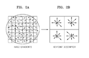
- FIGS. 2A and 2B are diagrams for describing a method of acquiring orientation information of feature points extracted from an ultrasound image based on the SIFT.
- the SIFT extracts feature points from an image and generates a feature descriptor of the extracted feature points, and orientation information may be included in the feature descriptor.
- the feature point extractor 105 extracts a pixel satisfying a predetermined criterion from an image as a feature point.
- the controller 140 generates a feature descriptor of the extracted feature point.
- the controller 140 generates a feature descriptor including location, size, and azimuth information with respect to surrounding pixels based on the extracted feature point.
- the controller 140 generates orientation information including one or more orientation histograms based on image gradients with respect to surrounding pixels about a finally selected feature point.
- a feature descriptor is generated as a 128-dimensional vector by storing parameters, such as image coordinates and a Gaussian scale of the feature point, in the orientation information.
- FIG. 2A shows an example of gradient values of surrounding pixels in an image from which a feature point is extracted
- FIG. 2B shows orientation histograms acquired using the gradient values.
- a direction and length of each of arrows indicate a direction and magnitude of a corresponding gradient, respectively.
- the controller 140 may acquire reversed orientation information by reversing the generated orientation information based on an arbitrary axis.
- FIGS. 3A and 3B are diagrams for describing a method of determining a symmetry axis of objects in the apparatus 100 for obtaining symmetry information of objects, according to an embodiment of the present invention.
- the first feature point acquiring unit 110 shown in FIG 1B , acquires a third feature point matched to the first feature point from a mirror image obtained by reversing the ultrasound image based on an arbitrary axis.
- the second feature point acquiring unit 120 acquires a second feature point corresponding to a location of the third feature point in the mirror image from the ultrasound image.
- first feature point in the ultrasound image and a location of the third feature point in the mirror image do not correspond to each other in the same image.
- second feature point corresponding to the location of the third feature point is acquired from the ultrasound image, the first feature point and the second feature point correspond to feature points symmetrical to each other about a symmetry axis.
- First feature points A, B, and C are extracted from an ultrasound image of objects 10, which is shown in FIG. 3A .
- second feature points A, B, and C are extracted from a mirror image of the ultrasound image, which is shown in FIG. 3B .
- 3B is generated by reversing the ultrasound image shown in FIG. 3A based on an axis connecting the feature points B and C. Arrows shown at the feature points B and C indicate orientation information at the feature points B and C, respectively. Assuming that I denotes a symmetry axis of the objects 10, the feature point C must be acquired as a feature point symmetrical to the feature point B of FIG. 3A .
- the feature point B of FIG. 3A will be matched with the feature point C of FIG. 3B because orientation information of the feature point B of FIG. 3A rotated clockwise by 180° corresponds to orientation information of the feature point C of FIG. 3B .
- a feature point corresponding to the feature point C of FIG. 3B is the feature point C of FIG. 3A
- the symmetry axis I may be determined using a center point between the feature points B and C of FIG. 3A .
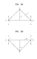
- FIGS. 4A and 4B are diagrams for describing a method of determining a symmetry axis of objects in the apparatus 100 for obtaining symmetry information of objects, according to another embodiment of the present invention.
- Feature points B and C are extracted from an ultrasound image shown in FIG. 4A .
- Arrows shown at the feature points B and C indicate orientation information at the feature points B and C, respectively.
- orientation information shown in FIG. 4B is acquired.
- the feature point C shown in FIG. 4A is extracted.
- a symmetry axis I may be determined using a center point between the feature points B and C.
- FIG. 5 is a flowchart illustrating a method of obtaining symmetry information of objects, according to an embodiment of the present invention.
- the method includes operations sequentially processed in the apparatus 100 shown in FIG. 1A .
- the description of the apparatus 100 shown in FIG. 1A also applies to the method of FIG. 5 .
- the feature point extractor 105 extracts at least one first feature point from an ultrasound image of objects.
- the feature point extractor 105 may extract feature points using at least one of the block matching algorithm, the SIFT, and the SURF.
- the feature point acquiring unit 108 acquires at least one second feature point having second orientation information which is reversed from orientation information of at least one first feature point based on an arbitrary axis.
- the symmetry axis determiner 130 determines a symmetry axis of the objects by using a center point between the first feature point and the second feature point.
- the symmetry axis determiner 130 determines the symmetry axis of the objects by using at least one of the RANSAC, the Hough transform, the BIG-M method, and the least squares method to exclude outlier data that is separate from an acquired center point data distribution from inlier data.
- the controller 140 acquires symmetry information indicating whether the objects are symmetrical about the determined symmetry axis.
- the symmetry information may be acquired by comparing any one of brightness, an edge shape, and a gradient of one of the areas of the objects, which are divided based on the symmetry axis, with a corresponding one of the other area.
- FIG. 6 is a flowchart illustrating a method of obtaining symmetry information of objects, according to another embodiment of the present invention.
- the feature point extractor 105 extracts at least one first feature point from an ultrasound image of objects and extracts at least one third feature point from a mirror image.
- the first feature point acquiring unit 110 acquires a third feature point matched to the first feature point from the mirror image. Whether the third feature point is matched to the first feature point may be determined using orientation information of the first feature point and the third feature point.
- the controller 140 acquires a second feature point corresponding to a location of the third feature point in the mirror image from the ultrasound image.
- the second feature point is symmetrical to the first feature point.
- the symmetry axis determiner 130 determines a symmetry axis of the objects by using a center point between the first feature point and the second feature point.
- the controller 140 acquires symmetry information indicating whether the objects are symmetrical about the determined symmetry axis.
- a symmetry axis of objects may be determined from an ultrasound image of the objects, and symmetry information indicating whether the objects are symmetrical about the determined symmetry axis may be acquired.
- the embodiments of the present invention can be written as computer programs and can be implemented in general-use digital computers that execute the programs using a computer-readable recording medium.
- Examples of the computer-readable recording medium include storage media such as magnetic storage media (e.g., ROM, floppy disks, hard disks, etc.), optical recording media (e.g., CD-ROMs, or DVDs), etc.
Landscapes
- Health & Medical Sciences (AREA)
- Engineering & Computer Science (AREA)
- Life Sciences & Earth Sciences (AREA)
- Physics & Mathematics (AREA)
- Medical Informatics (AREA)
- Public Health (AREA)
- Biomedical Technology (AREA)
- Pathology (AREA)
- Computer Vision & Pattern Recognition (AREA)
- General Health & Medical Sciences (AREA)
- Heart & Thoracic Surgery (AREA)
- Surgery (AREA)
- Veterinary Medicine (AREA)
- Animal Behavior & Ethology (AREA)
- Molecular Biology (AREA)
- Radiology & Medical Imaging (AREA)
- Nuclear Medicine, Radiotherapy & Molecular Imaging (AREA)
- Biophysics (AREA)
- Physiology (AREA)
- Theoretical Computer Science (AREA)
- General Physics & Mathematics (AREA)
- Geometry (AREA)
- Databases & Information Systems (AREA)
- Data Mining & Analysis (AREA)
- Primary Health Care (AREA)
- Epidemiology (AREA)
- Ultra Sonic Daignosis Equipment (AREA)
- Image Analysis (AREA)
- Image Processing (AREA)
Abstract

Description
- This application claims the benefit of Korean Patent Application No.
10-2012-0011795, filed on February 6, 2012 - The present invention relates to a method and apparatus for obtaining symmetry information of objects, and more particularly, to a method and apparatus for determining a symmetry axis of objects by using an ultrasound image of the objects and obtaining symmetry information of the objects.
- Ultrasound devices are mandatory to observe a structure inside an organism. Such an ultrasound device is a noninvasive diagnostic device that displays structural details, internal tissues, and a fluid flow of a human body.
- Such an ultrasound device transmits an ultrasound signal to an object through a human body and receives an echo signal reflected from the object, thereby displaying an image of a structure inside the human body.
- Objects, such as the brain, lungs, and kidneys, forming symmetry about a certain symmetry axis exist inside a human body. In a medical examination, determination on whether areas of objects divided based on a symmetry axis are symmetrical is important. Thus, an efficient method of determining whether objects are symmetrical is required.
- The present invention provides a method and apparatus for obtaining symmetry information of objects, whereby a symmetry axis of the objects is determined from an ultrasound image of the objects, and symmetry information indicating whether the objects are symmetrical about the determined symmetry axis is obtained.
- According to an aspect of the present invention, there is provided a method of obtaining symmetry information of objects, the method including: acquiring at least one second feature point having second orientation information corresponding to orientation information from a ultrasound image of the objects, wherein the orientation information is acquired by reversing first orientation information of at least one first feature point which is extracted from the ultrasound image, based on an arbitrary axis; determining a symmetry axis of the objects by using a center point between the at least one first feature point and the at least one second feature point; and acquiring symmetry information indicating whether the objects are symmetrical about the determined symmetry axis.
- The first orientation information and the second orientation information may include an orientation histogram.
- The acquiring the at least one second feature point may include: acquiring at least one third feature point matched to at least one first feature point of the objects, which are extracted from an ultrasound image of the objects, from a mirror image obtained by reversing the ultrasound image based on the arbitrary axis; and acquiring the at least one second feature point corresponding to a location of the third feature point in the mirror image from the ultrasound image.
- The acquiring the at least one third feature point may include acquiring the at least one third feature point having third orientation information corresponding to first orientation information of the at least one first feature point.
- The acquiring the symmetry information may include acquiring the symmetry information by using at least one of brightness, an edge shape, and a gradient of each first and second area divided based on the symmetry axis of the objects.
- The method may further include displaying an asymmetrical part of the first and second areas based on the acquired symmetry information.
- The method may further include extracting the at least one first feature point from the ultrasound image and the at least one third feature point from the mirror image by using at least one of a block matching algorithm, a Scale Invariant Feature Transform (SIFT), and Speeded-Up Robust Features (SURF).
- The determining the symmetry axis of the objects may include determining the symmetry axis of the objects by using at least one of a Random Sample Consensus (RANSAC), a Hough transform, a BIG-M method, and a least squares method.
- According to another aspect of the present invention, there is provided an apparatus for obtaining symmetry information of objects, the apparatus including: a feature point acquiring unit for acquiring at least one second feature point having second orientation information corresponding to orientation information from a ultrasound image of the objects, wherein the orientation information is acquired by reversing first orientation information of at least one first feature point which is extracted from the ultrasound image, based on an arbitrary axis; a symmetry axis determiner for determining a symmetry axis of the objects by using a center point between the at least one first feature point and the at least one second feature point; and a controller for acquiring symmetry information indicating whether the objects are symmetrical about the determined symmetry axis.
- The first orientation information and the second orientation information may include an orientation histogram.
- The feature point acquiring unit may include: a first feature point acquiring unit for acquiring at least one third feature point matched to at least one first feature point of the objects, from a mirror image obtained by reversing the ultrasound image based on an arbitrary axis; a second feature point acquiring unit for acquiring the at least one second feature point corresponding to a location of the at least one third feature point in the mirror image from the ultrasound image.
- The first feature point acquiring unit may acquire the at least one second third point having third orientation information corresponding to the first orientation information of the at least one first feature point.
- The controller may acquire the symmetry information by using at least one of brightness, an edge shape, and a gradient of each first and second area divided based on the symmetry axis of the objects.
- The apparatus may further include a display unit for displaying an asymmetrical part of the first and second areas based on the acquired symmetry information.
- The apparatus may further include a feature point extractor for extracting the at least one first feature point from the ultrasound image and the at least one third feature point from the mirror image by using at least one of a block matching algorithm, a Scale Invariant Feature Transform (SIFT), and Speeded-Up Robust Features (SURF).
- The symmetry axis determiner may determine the symmetry axis of the objects by using at least one of a Random Sample Consensus (RANSAC), a Hough transform, a BIG-M method, and a least squares method.
- A computer-readable program for executing the method of obtaining symmetry information of objects may be recorded in a computer-readable recording medium.
- The apparatus for obtaining symmetry information of objects may be included in an ultrasound apparatus.
- The above and other feature points and advantages of the present invention will become more apparent by describing in detail exemplary embodiments thereof with reference to the attached drawings in which:
-
FIG. 1A is a block diagram of an apparatus for obtaining symmetry information of objects, according to an embodiment of the present invention; -
FIG. 1B is a block diagram of an apparatus for obtaining symmetry information of objects, according to another embodiment of the present invention; -
FIGS. 2A and 2B are diagrams for describing a method of acquiring orientation information of feature points extracted from an ultrasound image based on a Scale Invariant Feature Transform (SIFT); -
FIGS. 3A and 3B are diagrams for describing a method of determining a symmetry axis of objects in the apparatus for obtaining symmetry information of objects, according to an embodiment of the present invention; -
FIGS. 4A and 4B are diagrams for describing a method of determining a symmetry axis of objects in the apparatus for obtaining symmetry information of objects, according to another embodiment of the present invention; -
FIG. 5 is a flowchart illustrating a method of obtaining symmetry information of objects, according to an embodiment of the present invention; and -
FIG. 6 is a flowchart illustrating a method of obtaining symmetry information of objects, according to another embodiment of the present invention. - The merits and characteristics of the present invention and methods for achieving them will be clear with reference to the embodiments described below in detail with the attached drawings. However, the present invention is not limited to the embodiments disclosed below, and the present invention will be implemented in various forms; rather, these embodiments are provided so that this disclosure will be thorough and complete, and will fully convey the concept of the invention to those of ordinary skill in the art. The present invention is only defined by the following claims. Like reference numbers are used to refer to like elements throughout the specification.
- The term 'unit' used in the embodiments indicates a software or hardware component, such as a Field Programmable Gate Array (FPGA) or Application Specific Integrated Circuit (ASIC), and performs a certain role. However, the term 'unit' is not limited to software or hardware. The term 'unit' may be configured to be in an addressable storage medium or to reproduce one or more processors. Thus, for example, the term 'unit' includes components, such as software components, object-oriented software components, class components, and task components, processors, functions, attributes, procedures, sub-routines, program code segments, drivers, firmware, micro-codes, circuits, data, databases, data structures, tables, arrays, and variables. A function provided in components and 'units' may be performed by combining a smaller number of components and 'units' or further separating additional components and 'units' therefrom.
- Expressions such as "at least one of," when preceding a list of elements, modify the entire list of elements and do not modify the individual elements of the list.
-
FIG. 1A is a block diagram of anapparatus 100 for obtaining symmetry information of objects, according to an embodiment of the present invention. - Referring to
FIG. 1A , theapparatus 100 according to an embodiment of the present invention may include a featurepoint acquiring unit 108, a symmetry axis determiner 130, and acontroller 140. Referring toFIG. 1B , theapparatus 100 according to another embodiment of the present invention may include a feature point extractor 1 05,a first featurepoint acquiring unit 110, a second featurepoint acquiring unit 120, the symmetry axis determiner 130, thecontroller 140, and thedisplay unit 150. - The
apparatus 100 may be included in an ultrasound apparatus, and each of thefeature point extractor 105, the featurepoint acquiring unit 108, the first featurepoint acquiring unit 110, the second featurepoint acquiring unit 120, the symmetry axis determiner 130, and thecontroller 140 may be implemented by a micro chip. The first featurepoint acquiring unit 110 and the second featurepoint acquiring unit 120 shown inFIG.1B may be included in the featurepoint acquiring unit 108 shown inFIG. 1A . - The
feature point extractor 105 extracts feature points indicating characteristics of objects from an ultrasound image of the objects. The extraction of feature points indicates a process of repeatedly extracting points at the same locations even though various transforms are performed on an image. In the image processing field, the extraction of feature points from an image is popularly used for techniques, such as object recognition and fingerprint recognition. - The
feature point extractor 105 may extract feature points from a specific image by using any one of a block matching algorithm, a Scale Invariant Feature Transform (SIFT), and Speeded-Up Robust Features (SURF). - The block matching algorithm is a method of dividing an image into blocks having a predetermined size and representing all pixels in each block as a single motion vector.
- The SIFT is an algorithm of extracting feature points not changed regardless of a size or rotation of an image and matching the extracted feature points with feature points extracted from another image.
- The SURF is also an algorithm of extracting feature points from an image and matching the extracted feature points with feature points extracted from another image, like the SIFT. However, a matching speed of the SURF is faster than that of the SIFT.
- The
feature point extractor 105 extracts at least one first feature point of the objects from an ultrasound image of the objects. In addition, thefeature point extractor 105 may extract at least one third feature point from a mirror image obtained by reversing the ultrasound image based on an arbitrary axis. Each of the number of extracted first feature points and the number of extracted second feature points may be plural. - The feature
point acquiring unit 108 acquires a second feature point which is symmetric with the first feature point. Thecontroller 140 acquires orientation information of the first feature point, and the featurepoint acquiring unit 108 may acquire the second feature point which is symmetric with the first feature point based on the acquired orientation information. Specifically, the featurepoint acquiring unit 108 acquires the second feature point having orientation information which is reversed from the orientation information of the first feature point based on an arbitrary axis. The orientation information will be described in detail below with reference toFIGS. 2A and 2B . - The
symmetry axis determiner 130 determines a symmetry axis of the objects by using a center point between the first feature point in the ultrasound image and the acquired second feature point. If a plurality of first feature points and a plurality of second feature points are acquired, the number of center points between the first feature points and the second feature points may be plural, and in this case, the symmetry axis of the objects may be determined by connecting the center points. - If a second feature point that is not symmetric with the first feature point is acquired, a center point between the first feature point and the acquired second feature point corresponds to data that is separate from the symmetry axis to be actually determined. That is, outlier data that is separate from a data distribution of acquired center points must be excluded from inlier data. To do this, the
symmetry axis determiner 130 determines the symmetry axis of the objects by using at least one of a Random Sample Consensus (RANSAC), a Hough transform, a BIG-M method, and a least squares method. According to these methods, a constant mathematical model is acquired by removing outlier data from among a plurality of center points. - The
controller 140 acquires symmetry information indicating whether the objects are symmetrical about the determined symmetry axis. In detail, the symmetry information of the objects is acquired by using at least one of brightness, an edge shape, and a gradient of each first and second area of the objects divided based on the symmetry axis of the objects. - The
display unit 150 displays an asymmetrical part of the first and second areas based on the symmetry information acquired by thecontroller 140. -
FIGS. 2A and 2B are diagrams for describing a method of acquiring orientation information of feature points extracted from an ultrasound image based on the SIFT. - The SIFT extracts feature points from an image and generates a feature descriptor of the extracted feature points, and orientation information may be included in the feature descriptor.
- First, the
feature point extractor 105 extracts a pixel satisfying a predetermined criterion from an image as a feature point. Thecontroller 140 generates a feature descriptor of the extracted feature point. - The
controller 140 generates a feature descriptor including location, size, and azimuth information with respect to surrounding pixels based on the extracted feature point. In detail, thecontroller 140 generates orientation information including one or more orientation histograms based on image gradients with respect to surrounding pixels about a finally selected feature point. A feature descriptor is generated as a 128-dimensional vector by storing parameters, such as image coordinates and a Gaussian scale of the feature point, in the orientation information. -
FIG. 2A shows an example of gradient values of surrounding pixels in an image from which a feature point is extracted, andFIG. 2B shows orientation histograms acquired using the gradient values. A direction and length of each of arrows indicate a direction and magnitude of a corresponding gradient, respectively. - The
controller 140 may acquire reversed orientation information by reversing the generated orientation information based on an arbitrary axis. -
FIGS. 3A and 3B are diagrams for describing a method of determining a symmetry axis of objects in theapparatus 100 for obtaining symmetry information of objects, according to an embodiment of the present invention. - The first feature
point acquiring unit 110, shown inFIG 1B , acquires a third feature point matched to the first feature point from a mirror image obtained by reversing the ultrasound image based on an arbitrary axis. - The second feature
point acquiring unit 120 acquires a second feature point corresponding to a location of the third feature point in the mirror image from the ultrasound image. - When the ultrasound image is reversed, orientation information of feature points included in the feature points is also reversed. Thus, a location of the first feature point in the ultrasound image and a location of the third feature point in the mirror image do not correspond to each other in the same image. If the second feature point corresponding to the location of the third feature point is acquired from the ultrasound image, the first feature point and the second feature point correspond to feature points symmetrical to each other about a symmetry axis. First feature points A, B, and C are extracted from an ultrasound image of
objects 10, which is shown inFIG. 3A . Then, second feature points A, B, and C are extracted from a mirror image of the ultrasound image, which is shown inFIG. 3B . The mirror image shown inFIG. 3B is generated by reversing the ultrasound image shown inFIG. 3A based on an axis connecting the feature points B and C. Arrows shown at the feature points B and C indicate orientation information at the feature points B and C, respectively. Assuming that I denotes a symmetry axis of theobjects 10, the feature point C must be acquired as a feature point symmetrical to the feature point B ofFIG. 3A . - When the feature points A, B, and C in the ultrasound image shown in
FIG. 3A are matched with the feature points A, B, and C in the mirror image shown inFIG. 3B , the feature point B ofFIG. 3A will be matched with the feature point C ofFIG. 3B because orientation information of the feature point B ofFIG. 3A rotated clockwise by 180° corresponds to orientation information of the feature point C ofFIG. 3B . In the ultrasound image, a feature point corresponding to the feature point C ofFIG. 3B is the feature point C ofFIG. 3A , and the symmetry axis I may be determined using a center point between the feature points B and C ofFIG. 3A . -
FIGS. 4A and 4B are diagrams for describing a method of determining a symmetry axis of objects in theapparatus 100 for obtaining symmetry information of objects, according to another embodiment of the present invention. - Feature points B and C are extracted from an ultrasound image shown in
FIG. 4A . Arrows shown at the feature points B and C indicate orientation information at the feature points B and C, respectively. When orientation information of the feature point B is reversed based on an axis connecting the feature points B and C, orientation information shown inFIG. 4B is acquired. When a feature point having orientation information corresponding to the acquired orientation information is searched for, the feature point C shown inFIG. 4A is extracted. A symmetry axis I may be determined using a center point between the feature points B and C. -
FIG. 5 is a flowchart illustrating a method of obtaining symmetry information of objects, according to an embodiment of the present invention. Referring toFIG. 5 , the method includes operations sequentially processed in theapparatus 100 shown inFIG. 1A . Thus, although omitted hereinafter, the description of theapparatus 100 shown inFIG. 1A also applies to the method ofFIG. 5 . - Referring to
FIG. 5 , in operation S10, thefeature point extractor 105 extracts at least one first feature point from an ultrasound image of objects. Thefeature point extractor 105 may extract feature points using at least one of the block matching algorithm, the SIFT, and the SURF. - In operation S20, the feature
point acquiring unit 108 acquires at least one second feature point having second orientation information which is reversed from orientation information of at least one first feature point based on an arbitrary axis. - In operation S30, the
symmetry axis determiner 130 determines a symmetry axis of the objects by using a center point between the first feature point and the second feature point. Thesymmetry axis determiner 130 determines the symmetry axis of the objects by using at least one of the RANSAC, the Hough transform, the BIG-M method, and the least squares method to exclude outlier data that is separate from an acquired center point data distribution from inlier data. - In operation S40, the
controller 140 acquires symmetry information indicating whether the objects are symmetrical about the determined symmetry axis. The symmetry information may be acquired by comparing any one of brightness, an edge shape, and a gradient of one of the areas of the objects, which are divided based on the symmetry axis, with a corresponding one of the other area. -
FIG. 6 is a flowchart illustrating a method of obtaining symmetry information of objects, according to another embodiment of the present invention. - Referring to
FIG. 6 , in operation S50, thefeature point extractor 105 extracts at least one first feature point from an ultrasound image of objects and extracts at least one third feature point from a mirror image. - In operation S60, the first feature
point acquiring unit 110 acquires a third feature point matched to the first feature point from the mirror image. Whether the third feature point is matched to the first feature point may be determined using orientation information of the first feature point and the third feature point. - In operation S70, the
controller 140 acquires a second feature point corresponding to a location of the third feature point in the mirror image from the ultrasound image. The second feature point is symmetrical to the first feature point. - In operation S80, the
symmetry axis determiner 130 determines a symmetry axis of the objects by using a center point between the first feature point and the second feature point. - In operation S70, the
controller 140 acquires symmetry information indicating whether the objects are symmetrical about the determined symmetry axis. - According to the embodiments of the present invention, a symmetry axis of objects may be determined from an ultrasound image of the objects, and symmetry information indicating whether the objects are symmetrical about the determined symmetry axis may be acquired.
- The embodiments of the present invention can be written as computer programs and can be implemented in general-use digital computers that execute the programs using a computer-readable recording medium. Examples of the computer-readable recording medium include storage media such as magnetic storage media (e.g., ROM, floppy disks, hard disks, etc.), optical recording media (e.g., CD-ROMs, or DVDs), etc.
- While the present invention has been particularly shown and described with reference to exemplary embodiments thereof, it will be understood by those of ordinary skill in the art that various changes in form and details may be made therein without departing from the spirit and scope of the present invention as defined by the following claims.
Claims (15)
- A method of obtaining symmetry information of objects, the method comprising:acquiring at least one second feature point having second orientation information corresponding to orientation information from a ultrasound image of the objects, wherein the orientation information is acquired by reversing first orientation information of at least one first feature point which is extracted from the ultrasound image, based on an arbitrary axis;determining a symmetry axis of the objects by using a center point between the at least one first feature point and the at least one second feature point; andacquiring symmetry information indicating whether the objects are symmetrical about the determined symmetry axis.
- The method of claim 1, wherein the first orientation information and the second orientation information include an orientation histogram.
- The method of claim 1, wherein the acquiring the at least one second feature point comprises:acquiring at least one third feature point matched to at least one first feature point of the objects, which are extracted from an ultrasound image of the objects, from a mirror image obtained by reversing the ultrasound image based on the arbitrary axis; andacquiring the at least one second feature point corresponding to a location of the third feature point in the mirror image from the ultrasound image.
- The method of claim 3, wherein the acquiring the at least one third feature point comprises acquiring the at least one third feature point having third orientation information corresponding to first orientation information of the at least one first feature point.
- The method of claim 1, wherein the acquiring the symmetry information comprises acquiring the symmetry information by using at least one of brightness, an edge shape, and a gradient of each first and second area divided based on the symmetry axis of the objects.
- The method of claim 5, further comprising displaying an asymmetrical part of the first and second areas based on the acquired symmetry information.
- The method of claim 3, further comprising extracting the at least one first feature point from the ultrasound image and the at least one third feature point from the mirror image by using at least one of a block matching algorithm, a Scale Invariant Feature Transform (SIFT), and Speeded-Up Robust Features (SURF).
- The method of claim 1, wherein the determining the symmetry axis of the objects comprises determining the symmetry axis of the objects by using at least one of a Random Sample Consensus (RANSAC), a Hough transform, a BIG-M method, and a least squares method.
- An apparatus for obtaining symmetry information of objects, the apparatus comprising:a feature point acquiring unit for acquiring at least one second feature point having second orientation information corresponding to orientation information from a ultrasound image of the objects, wherein the orientation information is acquired by reversing first orientation information of at least one first feature point which is extracted from the ultrasound image, based on an arbitrary axis;a symmetry axis determiner for determining a symmetry axis of the objects by using a center point between the at least one first feature point and the at least one second feature point; anda controller for acquiring symmetry information indicating whether the objects are symmetrical about the determined symmetry axis.
- The apparatus of claim 9, wherein the first orientation information and the second orientation information include an orientation histogram.
- The apparatus of claim 9, wherein the feature point acquiring unit comprises:a first feature point acquiring unit for acquiring at least one third feature point matched to at least one first feature point of the objects, from a mirror image obtained by reversing the ultrasound image based on an arbitrary axis;a second feature point acquiring unit for acquiring the at least one second feature point corresponding to a location of the at least one third feature point in the mirror image from the ultrasound image.
- The apparatus of claim 11, wherein the first feature point acquiring unit acquires the at least one second third point having third orientation information corresponding to the first orientation information of the at least one first feature point.
- The apparatus of claim 9, wherein the controller acquires the symmetry information by using at least one of brightness, an edge shape, and a gradient of each first and second area divided based on the symmetry axis of the objects.
- The apparatus of claim 13, further comprising a display unit for displaying an asymmetrical part of the first and second areas based on the acquired symmetry information.
- A computer-readable recording medium storing a computer-readable program for executing the method of any one of claims 1 through 8.
Applications Claiming Priority (1)
| Application Number | Priority Date | Filing Date | Title |
|---|---|---|---|
| KR1020120011795A KR101423923B1 (en) | 2012-02-06 | 2012-02-06 | Apparatus and method for obtainning a symmetry information of objects |
Publications (2)
| Publication Number | Publication Date |
|---|---|
| EP2624009A1 true EP2624009A1 (en) | 2013-08-07 |
| EP2624009B1 EP2624009B1 (en) | 2014-09-03 |
Family
ID=47722008
Family Applications (1)
| Application Number | Title | Priority Date | Filing Date |
|---|---|---|---|
| EP13153866.2A Active EP2624009B1 (en) | 2012-02-06 | 2013-02-04 | Method and apparatus for obtaining symmetry information of objects |
Country Status (3)
| Country | Link |
|---|---|
| US (1) | US9076063B2 (en) |
| EP (1) | EP2624009B1 (en) |
| KR (1) | KR101423923B1 (en) |
Cited By (1)
| Publication number | Priority date | Publication date | Assignee | Title |
|---|---|---|---|---|
| CN119745506A (en) * | 2025-03-07 | 2025-04-04 | 骨圣元化机器人(深圳)有限公司 | Spinal surgery nail placement path planning method, equipment and computer program product |
Families Citing this family (10)
| Publication number | Priority date | Publication date | Assignee | Title |
|---|---|---|---|---|
| IT1401952B1 (en) * | 2010-09-22 | 2013-08-28 | Henesis S R L | SYSTEM AND METHOD FOR PANTOGRAPH MONITORING. |
| US9779504B1 (en) | 2011-12-14 | 2017-10-03 | Atti International Services Company, Inc. | Method and system for identifying anomalies in medical images especially those including one of a pair of symmetric body parts |
| US9401021B1 (en) | 2011-12-14 | 2016-07-26 | Atti International Services Company, Inc. | Method and system for identifying anomalies in medical images especially those including body parts having symmetrical properties |
| US10667790B2 (en) | 2012-03-26 | 2020-06-02 | Teratech Corporation | Tablet ultrasound system |
| US9877699B2 (en) | 2012-03-26 | 2018-01-30 | Teratech Corporation | Tablet ultrasound system |
| CN103559494A (en) * | 2013-10-30 | 2014-02-05 | 中国矿业大学(北京) | Method for detecting symmetry axis of plane figure object |
| CN106370100A (en) * | 2016-08-17 | 2017-02-01 | 北京汽车股份有限公司 | Vehicle body symmetry deviation detection method and system |
| CN110167449A (en) | 2016-11-16 | 2019-08-23 | 德拉工业公司 | Portable ultrasound system |
| KR102189952B1 (en) * | 2018-09-21 | 2020-12-11 | 연세대학교 산학협력단 | Patient Specific 3D Surgical Cutting Guide for Bone, Manufacturing Method Thereof, Recording Medium Therefor, Manufacturing Apparatus Therefor |
| WO2022141085A1 (en) * | 2020-12-29 | 2022-07-07 | 深圳迈瑞生物医疗电子股份有限公司 | Ultrasonic detection method and ultrasonic imaging system |
Citations (2)
| Publication number | Priority date | Publication date | Assignee | Title |
|---|---|---|---|---|
| US5889892A (en) | 1996-05-29 | 1999-03-30 | Nec Corporation | Line symmetrical figure shaping apparatus |
| US5966472A (en) * | 1996-08-07 | 1999-10-12 | Komatsu Limited | Method for automatic recognition of a concavity or convexity |
Family Cites Families (9)
| Publication number | Priority date | Publication date | Assignee | Title |
|---|---|---|---|---|
| USRE45759E1 (en) * | 2001-07-31 | 2015-10-20 | Koninklijke Philips N.V. | Transesophageal and transnasal, transesophageal ultrasound imaging systems |
| FR2840710B1 (en) | 2002-06-11 | 2005-01-07 | Ge Med Sys Global Tech Co Llc | DIGITAL IMAGE PROCESSING SYSTEM, IMAGING INSTALLATION INCORPORATING SUCH A SYSTEM, AND CORRESPONDING IMAGE PROCESSING METHOD |
| JP4114682B2 (en) | 2005-07-14 | 2008-07-09 | 日産自動車株式会社 | VEHICLE DRIVE OPERATION ASSISTANCE DEVICE AND VEHICLE WITH VEHICLE DRIVE OPERATION ASSISTANCE DEVICE |
| JP2007104551A (en) | 2005-10-07 | 2007-04-19 | Matsushita Electric Ind Co Ltd | Remote control transmitter |
| DE102005052993B4 (en) | 2005-11-07 | 2014-08-21 | Siemens Aktiengesellschaft | Method for the automated evaluation of a three-dimensional image of a side-symmetrical organ system |
| KR20110057749A (en) | 2009-11-25 | 2011-06-01 | 삼성메디슨 주식회사 | Ultrasound system and method for correcting distortion in ultrasound images |
| US9134420B2 (en) * | 2010-03-10 | 2015-09-15 | Samsung Medison Co., Ltd. | Three-dimensional (3D) ultrasound system for scanning object inside human body and method for operating 3D ultrasound system |
| KR101229490B1 (en) * | 2010-05-31 | 2013-02-04 | 삼성메디슨 주식회사 | 3d ultrasound apparatus and method for operating thereof |
| US8675939B2 (en) * | 2010-07-13 | 2014-03-18 | Stryker Leibinger Gmbh & Co. Kg | Registration of anatomical data sets |
-
2012
- 2012-02-06 KR KR1020120011795A patent/KR101423923B1/en active Active
-
2013
- 2013-02-04 EP EP13153866.2A patent/EP2624009B1/en active Active
- 2013-02-05 US US13/759,936 patent/US9076063B2/en active Active
Patent Citations (2)
| Publication number | Priority date | Publication date | Assignee | Title |
|---|---|---|---|---|
| US5889892A (en) | 1996-05-29 | 1999-03-30 | Nec Corporation | Line symmetrical figure shaping apparatus |
| US5966472A (en) * | 1996-08-07 | 1999-10-12 | Komatsu Limited | Method for automatic recognition of a concavity or convexity |
Non-Patent Citations (2)
| Title |
|---|
| SHIH-KUAN LIAO ET AL: "Segmentation of Natural Image Based on Symmetry Features", INNOVATIVE COMPUTING, INFORMATION AND CONTROL (ICICIC), 2009 FOURTH INTERNATIONAL CONFERENCE ON, IEEE, PISCATAWAY, NJ, USA, 7 December 2009 (2009-12-07), pages 523 - 527, XP031627144, ISBN: 978-1-4244-5543-0 * |
| SHIH-KUAN LIAO: "Segmentation of Natural Image Based on Symmetry Features", INNOVATIVE COMPUTING, INFORMATION AND CONTROL (ICICIC) 2009 FOURTH )NTERNAT)ONAL CONFERECE, 7 December 2009 (2009-12-07), pages 523 - 527, XP031627144 |
Cited By (2)
| Publication number | Priority date | Publication date | Assignee | Title |
|---|---|---|---|---|
| CN119745506A (en) * | 2025-03-07 | 2025-04-04 | 骨圣元化机器人(深圳)有限公司 | Spinal surgery nail placement path planning method, equipment and computer program product |
| CN119745506B (en) * | 2025-03-07 | 2025-06-03 | 骨圣元化机器人(深圳)有限公司 | Spinal surgery nail placement path planning method, equipment and computer program product |
Also Published As
| Publication number | Publication date |
|---|---|
| KR20130090563A (en) | 2013-08-14 |
| EP2624009B1 (en) | 2014-09-03 |
| KR101423923B1 (en) | 2014-08-13 |
| US9076063B2 (en) | 2015-07-07 |
| US20130202174A1 (en) | 2013-08-08 |
Similar Documents
| Publication | Publication Date | Title |
|---|---|---|
| US9076063B2 (en) | Method and apparatus for obtaining symmetry information of objects | |
| US10846853B2 (en) | Medical image processing apparatus, medical image processing method, and medical image processing program | |
| US8761475B2 (en) | System and method for automatic recognition and labeling of anatomical structures and vessels in medical imaging scans | |
| CN109478321B (en) | Automated 3D brain tumor segmentation and classification | |
| US10062161B2 (en) | Endoscopic image diagnosis support system for computing average values of identification probabilities of pathological types | |
| CN108399374B (en) | Method and apparatus for selecting candidate fingerprint images for fingerprint recognition | |
| US11276490B2 (en) | Method and apparatus for classification of lesion based on learning data applying one or more augmentation methods in lesion information augmented patch of medical image | |
| CN108765315B (en) | Image completion method, device, computer equipment and storage medium | |
| TWI684994B (en) | Spline image registration method | |
| JP7104375B2 (en) | Treatment support device, treatment support method, and program | |
| CN105678778B (en) | An image matching method and device | |
| JP6410450B2 (en) | Object identification device, object identification method, and program | |
| JP6041781B2 (en) | MEDICAL IMAGE PROCESSING DEVICE, ITS OPERATION METHOD, AND MEDICAL IMAGE PROCESSING PROGRAM | |
| Gomes et al. | Visual attention guided features selection with foveated images | |
| CN117462164B (en) | Ultrasonic image acquisition method, device, computer equipment and storage medium | |
| JP6702118B2 (en) | Diagnosis support device, image processing method in the diagnosis support device, and program | |
| JP6781417B2 (en) | Diencephalon registration | |
| CN109815791B (en) | Blood vessel-based identification method and device | |
| Zhang et al. | Retinal vessel segmentation using Gabor filter and textons | |
| US10249050B2 (en) | Image processing apparatus and image processing method | |
| JP7807656B2 (en) | IMAGE IDENTIFICATION PROGRAM, IMAGE IDENTIFICATION METHOD, IMAGE IDENTIFICATION DEVICE, AND INFORMATION PROCESSING SYSTEM | |
| CN107358224B (en) | Method for detecting outer iris outline in cataract surgery | |
| CN115409689A (en) | Multi-mode retina fundus image registration method and device | |
| CN113705660A (en) | Target identification method and related equipment | |
| Sheeba et al. | Splitting of overlapping cells in peripheral blood smear images by concavity analysis |
Legal Events
| Date | Code | Title | Description |
|---|---|---|---|
| PUAI | Public reference made under article 153(3) epc to a published international application that has entered the european phase |
Free format text: ORIGINAL CODE: 0009012 |
|
| AK | Designated contracting states |
Kind code of ref document: A1 Designated state(s): AL AT BE BG CH CY CZ DE DK EE ES FI FR GB GR HR HU IE IS IT LI LT LU LV MC MK MT NL NO PL PT RO RS SE SI SK SM TR |
|
| AX | Request for extension of the european patent |
Extension state: BA ME |
|
| 17P | Request for examination filed |
Effective date: 20140207 |
|
| RBV | Designated contracting states (corrected) |
Designated state(s): AL AT BE BG CH CY CZ DE DK EE ES FI FR GB GR HR HU IE IS IT LI LT LU LV MC MK MT NL NO PL PT RO RS SE SI SK SM TR |
|
| GRAJ | Information related to disapproval of communication of intention to grant by the applicant or resumption of examination proceedings by the epo deleted |
Free format text: ORIGINAL CODE: EPIDOSDIGR1 |
|
| GRAP | Despatch of communication of intention to grant a patent |
Free format text: ORIGINAL CODE: EPIDOSNIGR1 |
|
| GRAP | Despatch of communication of intention to grant a patent |
Free format text: ORIGINAL CODE: EPIDOSNIGR1 |
|
| INTG | Intention to grant announced |
Effective date: 20140402 |
|
| INTG | Intention to grant announced |
Effective date: 20140409 |
|
| GRAS | Grant fee paid |
Free format text: ORIGINAL CODE: EPIDOSNIGR3 |
|
| GRAA | (expected) grant |
Free format text: ORIGINAL CODE: 0009210 |
|
| AK | Designated contracting states |
Kind code of ref document: B1 Designated state(s): AL AT BE BG CH CY CZ DE DK EE ES FI FR GB GR HR HU IE IS IT LI LT LU LV MC MK MT NL NO PL PT RO RS SE SI SK SM TR |
|
| REG | Reference to a national code |
Ref country code: GB Ref legal event code: FG4D |
|
| REG | Reference to a national code |
Ref country code: CH Ref legal event code: EP Ref country code: AT Ref legal event code: REF Ref document number: 685879 Country of ref document: AT Kind code of ref document: T Effective date: 20140915 |
|
| REG | Reference to a national code |
Ref country code: IE Ref legal event code: FG4D |
|
| REG | Reference to a national code |
Ref country code: DE Ref legal event code: R096 Ref document number: 602013000214 Country of ref document: DE Effective date: 20141016 |
|
| REG | Reference to a national code |
Ref country code: NL Ref legal event code: T3 |
|
| REG | Reference to a national code |
Ref country code: AT Ref legal event code: MK05 Ref document number: 685879 Country of ref document: AT Kind code of ref document: T Effective date: 20140903 |
|
| PG25 | Lapsed in a contracting state [announced via postgrant information from national office to epo] |
Ref country code: SE Free format text: LAPSE BECAUSE OF FAILURE TO SUBMIT A TRANSLATION OF THE DESCRIPTION OR TO PAY THE FEE WITHIN THE PRESCRIBED TIME-LIMIT Effective date: 20140903 Ref country code: NO Free format text: LAPSE BECAUSE OF FAILURE TO SUBMIT A TRANSLATION OF THE DESCRIPTION OR TO PAY THE FEE WITHIN THE PRESCRIBED TIME-LIMIT Effective date: 20141203 Ref country code: GR Free format text: LAPSE BECAUSE OF FAILURE TO SUBMIT A TRANSLATION OF THE DESCRIPTION OR TO PAY THE FEE WITHIN THE PRESCRIBED TIME-LIMIT Effective date: 20141204 Ref country code: LT Free format text: LAPSE BECAUSE OF FAILURE TO SUBMIT A TRANSLATION OF THE DESCRIPTION OR TO PAY THE FEE WITHIN THE PRESCRIBED TIME-LIMIT Effective date: 20140903 Ref country code: ES Free format text: LAPSE BECAUSE OF FAILURE TO SUBMIT A TRANSLATION OF THE DESCRIPTION OR TO PAY THE FEE WITHIN THE PRESCRIBED TIME-LIMIT Effective date: 20140903 Ref country code: FI Free format text: LAPSE BECAUSE OF FAILURE TO SUBMIT A TRANSLATION OF THE DESCRIPTION OR TO PAY THE FEE WITHIN THE PRESCRIBED TIME-LIMIT Effective date: 20140903 |
|
| REG | Reference to a national code |
Ref country code: LT Ref legal event code: MG4D |
|
| PG25 | Lapsed in a contracting state [announced via postgrant information from national office to epo] |
Ref country code: RS Free format text: LAPSE BECAUSE OF FAILURE TO SUBMIT A TRANSLATION OF THE DESCRIPTION OR TO PAY THE FEE WITHIN THE PRESCRIBED TIME-LIMIT Effective date: 20140903 Ref country code: LV Free format text: LAPSE BECAUSE OF FAILURE TO SUBMIT A TRANSLATION OF THE DESCRIPTION OR TO PAY THE FEE WITHIN THE PRESCRIBED TIME-LIMIT Effective date: 20140903 Ref country code: HR Free format text: LAPSE BECAUSE OF FAILURE TO SUBMIT A TRANSLATION OF THE DESCRIPTION OR TO PAY THE FEE WITHIN THE PRESCRIBED TIME-LIMIT Effective date: 20140903 Ref country code: CY Free format text: LAPSE BECAUSE OF FAILURE TO SUBMIT A TRANSLATION OF THE DESCRIPTION OR TO PAY THE FEE WITHIN THE PRESCRIBED TIME-LIMIT Effective date: 20140903 Ref country code: AT Free format text: LAPSE BECAUSE OF FAILURE TO SUBMIT A TRANSLATION OF THE DESCRIPTION OR TO PAY THE FEE WITHIN THE PRESCRIBED TIME-LIMIT Effective date: 20140903 |
|
| PG25 | Lapsed in a contracting state [announced via postgrant information from national office to epo] |
Ref country code: PT Free format text: LAPSE BECAUSE OF FAILURE TO SUBMIT A TRANSLATION OF THE DESCRIPTION OR TO PAY THE FEE WITHIN THE PRESCRIBED TIME-LIMIT Effective date: 20150105 Ref country code: EE Free format text: LAPSE BECAUSE OF FAILURE TO SUBMIT A TRANSLATION OF THE DESCRIPTION OR TO PAY THE FEE WITHIN THE PRESCRIBED TIME-LIMIT Effective date: 20140903 Ref country code: SK Free format text: LAPSE BECAUSE OF FAILURE TO SUBMIT A TRANSLATION OF THE DESCRIPTION OR TO PAY THE FEE WITHIN THE PRESCRIBED TIME-LIMIT Effective date: 20140903 Ref country code: RO Free format text: LAPSE BECAUSE OF FAILURE TO SUBMIT A TRANSLATION OF THE DESCRIPTION OR TO PAY THE FEE WITHIN THE PRESCRIBED TIME-LIMIT Effective date: 20140903 Ref country code: IS Free format text: LAPSE BECAUSE OF FAILURE TO SUBMIT A TRANSLATION OF THE DESCRIPTION OR TO PAY THE FEE WITHIN THE PRESCRIBED TIME-LIMIT Effective date: 20150103 Ref country code: CZ Free format text: LAPSE BECAUSE OF FAILURE TO SUBMIT A TRANSLATION OF THE DESCRIPTION OR TO PAY THE FEE WITHIN THE PRESCRIBED TIME-LIMIT Effective date: 20140903 |
|
| PG25 | Lapsed in a contracting state [announced via postgrant information from national office to epo] |
Ref country code: PL Free format text: LAPSE BECAUSE OF FAILURE TO SUBMIT A TRANSLATION OF THE DESCRIPTION OR TO PAY THE FEE WITHIN THE PRESCRIBED TIME-LIMIT Effective date: 20140903 |
|
| REG | Reference to a national code |
Ref country code: DE Ref legal event code: R097 Ref document number: 602013000214 Country of ref document: DE |
|
| PLBE | No opposition filed within time limit |
Free format text: ORIGINAL CODE: 0009261 |
|
| STAA | Information on the status of an ep patent application or granted ep patent |
Free format text: STATUS: NO OPPOSITION FILED WITHIN TIME LIMIT |
|
| PG25 | Lapsed in a contracting state [announced via postgrant information from national office to epo] |
Ref country code: DK Free format text: LAPSE BECAUSE OF FAILURE TO SUBMIT A TRANSLATION OF THE DESCRIPTION OR TO PAY THE FEE WITHIN THE PRESCRIBED TIME-LIMIT Effective date: 20140903 |
|
| 26N | No opposition filed |
Effective date: 20150604 |
|
| PG25 | Lapsed in a contracting state [announced via postgrant information from national office to epo] |
Ref country code: LU Free format text: LAPSE BECAUSE OF FAILURE TO SUBMIT A TRANSLATION OF THE DESCRIPTION OR TO PAY THE FEE WITHIN THE PRESCRIBED TIME-LIMIT Effective date: 20150204 |
|
| PG25 | Lapsed in a contracting state [announced via postgrant information from national office to epo] |
Ref country code: MC Free format text: LAPSE BECAUSE OF FAILURE TO SUBMIT A TRANSLATION OF THE DESCRIPTION OR TO PAY THE FEE WITHIN THE PRESCRIBED TIME-LIMIT Effective date: 20140903 |
|
| REG | Reference to a national code |
Ref country code: IE Ref legal event code: MM4A |
|
| PG25 | Lapsed in a contracting state [announced via postgrant information from national office to epo] |
Ref country code: SI Free format text: LAPSE BECAUSE OF FAILURE TO SUBMIT A TRANSLATION OF THE DESCRIPTION OR TO PAY THE FEE WITHIN THE PRESCRIBED TIME-LIMIT Effective date: 20140903 |
|
| REG | Reference to a national code |
Ref country code: FR Ref legal event code: PLFP Year of fee payment: 4 |
|
| PG25 | Lapsed in a contracting state [announced via postgrant information from national office to epo] |
Ref country code: IE Free format text: LAPSE BECAUSE OF NON-PAYMENT OF DUE FEES Effective date: 20150204 |
|
| PG25 | Lapsed in a contracting state [announced via postgrant information from national office to epo] |
Ref country code: BE Free format text: LAPSE BECAUSE OF FAILURE TO SUBMIT A TRANSLATION OF THE DESCRIPTION OR TO PAY THE FEE WITHIN THE PRESCRIBED TIME-LIMIT Effective date: 20140903 |
|
| REG | Reference to a national code |
Ref country code: CH Ref legal event code: PL |
|
| PG25 | Lapsed in a contracting state [announced via postgrant information from national office to epo] |
Ref country code: LI Free format text: LAPSE BECAUSE OF NON-PAYMENT OF DUE FEES Effective date: 20160229 Ref country code: CH Free format text: LAPSE BECAUSE OF NON-PAYMENT OF DUE FEES Effective date: 20160229 |
|
| PG25 | Lapsed in a contracting state [announced via postgrant information from national office to epo] |
Ref country code: MT Free format text: LAPSE BECAUSE OF FAILURE TO SUBMIT A TRANSLATION OF THE DESCRIPTION OR TO PAY THE FEE WITHIN THE PRESCRIBED TIME-LIMIT Effective date: 20140903 |
|
| REG | Reference to a national code |
Ref country code: FR Ref legal event code: PLFP Year of fee payment: 5 |
|
| PG25 | Lapsed in a contracting state [announced via postgrant information from national office to epo] |
Ref country code: HU Free format text: LAPSE BECAUSE OF FAILURE TO SUBMIT A TRANSLATION OF THE DESCRIPTION OR TO PAY THE FEE WITHIN THE PRESCRIBED TIME-LIMIT; INVALID AB INITIO Effective date: 20130204 Ref country code: BG Free format text: LAPSE BECAUSE OF FAILURE TO SUBMIT A TRANSLATION OF THE DESCRIPTION OR TO PAY THE FEE WITHIN THE PRESCRIBED TIME-LIMIT Effective date: 20140903 |
|
| PG25 | Lapsed in a contracting state [announced via postgrant information from national office to epo] |
Ref country code: TR Free format text: LAPSE BECAUSE OF FAILURE TO SUBMIT A TRANSLATION OF THE DESCRIPTION OR TO PAY THE FEE WITHIN THE PRESCRIBED TIME-LIMIT Effective date: 20140903 |
|
| GBPC | Gb: european patent ceased through non-payment of renewal fee |
Effective date: 20170204 |
|
| REG | Reference to a national code |
Ref country code: FR Ref legal event code: PLFP Year of fee payment: 6 |
|
| PG25 | Lapsed in a contracting state [announced via postgrant information from national office to epo] |
Ref country code: GB Free format text: LAPSE BECAUSE OF NON-PAYMENT OF DUE FEES Effective date: 20170204 |
|
| PG25 | Lapsed in a contracting state [announced via postgrant information from national office to epo] |
Ref country code: SM Free format text: LAPSE BECAUSE OF FAILURE TO SUBMIT A TRANSLATION OF THE DESCRIPTION OR TO PAY THE FEE WITHIN THE PRESCRIBED TIME-LIMIT Effective date: 20140903 |
|
| PG25 | Lapsed in a contracting state [announced via postgrant information from national office to epo] |
Ref country code: MK Free format text: LAPSE BECAUSE OF FAILURE TO SUBMIT A TRANSLATION OF THE DESCRIPTION OR TO PAY THE FEE WITHIN THE PRESCRIBED TIME-LIMIT Effective date: 20140903 |
|
| PG25 | Lapsed in a contracting state [announced via postgrant information from national office to epo] |
Ref country code: AL Free format text: LAPSE BECAUSE OF FAILURE TO SUBMIT A TRANSLATION OF THE DESCRIPTION OR TO PAY THE FEE WITHIN THE PRESCRIBED TIME-LIMIT Effective date: 20140903 |
|
| PGFP | Annual fee paid to national office [announced via postgrant information from national office to epo] |
Ref country code: NL Payment date: 20200107 Year of fee payment: 8 |
|
| REG | Reference to a national code |
Ref country code: NL Ref legal event code: MM Effective date: 20210301 |
|
| PG25 | Lapsed in a contracting state [announced via postgrant information from national office to epo] |
Ref country code: NL Free format text: LAPSE BECAUSE OF NON-PAYMENT OF DUE FEES Effective date: 20210301 |
|
| PGFP | Annual fee paid to national office [announced via postgrant information from national office to epo] |
Ref country code: DE Payment date: 20260105 Year of fee payment: 14 |
|
| PGFP | Annual fee paid to national office [announced via postgrant information from national office to epo] |
Ref country code: IT Payment date: 20260108 Year of fee payment: 14 |
|
| PGFP | Annual fee paid to national office [announced via postgrant information from national office to epo] |
Ref country code: FR Payment date: 20260108 Year of fee payment: 14 |