EP2623971A1 - Capacitance-based moisture sensor - Google Patents
Capacitance-based moisture sensor Download PDFInfo
- Publication number
- EP2623971A1 EP2623971A1 EP13153427.3A EP13153427A EP2623971A1 EP 2623971 A1 EP2623971 A1 EP 2623971A1 EP 13153427 A EP13153427 A EP 13153427A EP 2623971 A1 EP2623971 A1 EP 2623971A1
- Authority
- EP
- European Patent Office
- Prior art keywords
- capacitance
- frequency output
- based moisture
- sensor
- soil
- Prior art date
- Legal status (The legal status is an assumption and is not a legal conclusion. Google has not performed a legal analysis and makes no representation as to the accuracy of the status listed.)
- Withdrawn
Links
- 239000002689 soil Substances 0.000 claims abstract description 68
- 239000000463 material Substances 0.000 claims abstract description 36
- 239000003990 capacitor Substances 0.000 claims abstract description 20
- XLYOFNOQVPJJNP-UHFFFAOYSA-N water Substances O XLYOFNOQVPJJNP-UHFFFAOYSA-N 0.000 claims description 40
- 238000000034 method Methods 0.000 claims description 33
- 239000011159 matrix material Substances 0.000 claims description 17
- 229920006395 saturated elastomer Polymers 0.000 claims description 13
- 238000009738 saturating Methods 0.000 claims 1
- 239000000523 sample Substances 0.000 description 18
- 239000000126 substance Substances 0.000 description 5
- RYGMFSIKBFXOCR-UHFFFAOYSA-N Copper Chemical compound [Cu] RYGMFSIKBFXOCR-UHFFFAOYSA-N 0.000 description 3
- 229910052802 copper Inorganic materials 0.000 description 3
- 239000010949 copper Substances 0.000 description 3
- 230000005684 electric field Effects 0.000 description 3
- 238000005259 measurement Methods 0.000 description 3
- 238000013508 migration Methods 0.000 description 3
- 230000005012 migration Effects 0.000 description 3
- HPNSNYBUADCFDR-UHFFFAOYSA-N chromafenozide Chemical compound CC1=CC(C)=CC(C(=O)N(NC(=O)C=2C(=C3CCCOC3=CC=2)C)C(C)(C)C)=C1 HPNSNYBUADCFDR-UHFFFAOYSA-N 0.000 description 2
- 238000004891 communication Methods 0.000 description 2
- 238000003780 insertion Methods 0.000 description 2
- 230000037431 insertion Effects 0.000 description 2
- 239000004576 sand Substances 0.000 description 2
- 238000012360 testing method Methods 0.000 description 2
- 230000000712 assembly Effects 0.000 description 1
- 238000000429 assembly Methods 0.000 description 1
- 239000004927 clay Substances 0.000 description 1
- 238000005056 compaction Methods 0.000 description 1
- 238000013461 design Methods 0.000 description 1
- 230000000694 effects Effects 0.000 description 1
- 239000011521 glass Substances 0.000 description 1
- 230000005484 gravity Effects 0.000 description 1
- 238000009434 installation Methods 0.000 description 1
- 238000012544 monitoring process Methods 0.000 description 1
- 230000010355 oscillation Effects 0.000 description 1
- 238000012545 processing Methods 0.000 description 1
- 230000000087 stabilizing effect Effects 0.000 description 1
- 238000004448 titration Methods 0.000 description 1
Images


Classifications
-
- G—PHYSICS
- G01—MEASURING; TESTING
- G01N—INVESTIGATING OR ANALYSING MATERIALS BY DETERMINING THEIR CHEMICAL OR PHYSICAL PROPERTIES
- G01N27/00—Investigating or analysing materials by the use of electric, electrochemical, or magnetic means
- G01N27/02—Investigating or analysing materials by the use of electric, electrochemical, or magnetic means by investigating impedance
- G01N27/22—Investigating or analysing materials by the use of electric, electrochemical, or magnetic means by investigating impedance by investigating capacitance
- G01N27/223—Investigating or analysing materials by the use of electric, electrochemical, or magnetic means by investigating impedance by investigating capacitance for determining moisture content, e.g. humidity
-
- G—PHYSICS
- G01—MEASURING; TESTING
- G01N—INVESTIGATING OR ANALYSING MATERIALS BY DETERMINING THEIR CHEMICAL OR PHYSICAL PROPERTIES
- G01N33/00—Investigating or analysing materials by specific methods not covered by groups G01N1/00 - G01N31/00
- G01N33/24—Earth materials
- G01N33/246—Earth materials for water content
Definitions
- This invention relates generally to moisture sensing of soil or other materials, and more specifically to capacitance-based moisture sensors.
- volumetric water content of soil or other materials may be measured using a probe having one or more capacitance-based moisture sensors.
- Each capacitance-based moisture sensor may include two conductive rings spaced by a dielectric to form a capacitor.
- the sensors may be arranged and fastened inside a probe which may be a plastic access tube that may be inserted in the soil.
- the electric field of each capacitor extends beyond the access tube and interacts with the soil around the tube to make the value of the capacitor variable.
- US Patent 5418466 entitled “Moisture and Salinity Sensor and Method of Use” relating to moisture and salinity measurement and in particular to a sensor and its method of use which may provide values for the moisture/complex dielectric constant of a variety of mediums.
- a sensor apparatus is arranged for indicating the complex dielectric constant and conductivity of a medium and uses a tuned circuit. The tuned circuit oscillates such that the frequency of oscillation is representative of the complex dielectric constant of the medium.
- Capacitance-based moisture sensors must be calibrated. Calibration needs to be done for each different sensor design and soil type. Calibration may be accomplished by measuring the frequency response of a representative sensor to a specified soil at several different volumetric water contents. The calibration process may involve installing one or more sensor assemblies in an open field of a specified soil type and monitoring the sensor response as water is added to the soil. The process may require stabilizing the soil for several days or weeks before each of the soil samples may be physically removed and analyzed to establish a fitted response curve to the soil readings. At each of the various moisture contents, the soil may be removed and sectioned with earth moving equipment to obtain a physical soil sample for volumetric analysis. This calibration process may be time and labor intensive. A more efficient and cost effective calibration apparatus and method is needed for capacitance-based moisture sensors for soil or other materials.
- US Patent 7042234 entitled “Soil Matric Potential and Salinity Measurement Apparatus and Method of Use” relates to a soil measurement arrangement that includes a capacitive based soil moisture and salinity sensor, a predetermined moisture migration medium located in a volume adjacent said sensor so that the medium substantially occupies the field of influence of said sensor.
- the medium is in moisture communication with the soil to be measured, and said sensor is adapted to measure and produce data representative of the volumetric water content of said medium.
- a sensor data processing means determines both the soil moisture and salinity of said medium.
- the measured volumetric soil moisture content and the moisture release curve of the medium By using the measured volumetric soil moisture content and the moisture release curve of the medium, it is possible to derive the matric potential of the soil.
- the measured salinity of the medium corresponds to the salinity of the soil that is in moisture communication with the medium.
- a migration medium may increases the hole diameter for in-ground installation of the sensor and requires additional time and cost.
- the sensor may include a sleeve having an internal cavity, a container filled with soil or other material inserted into the internal cavity, and a pair of ring-shaped conductive bands around the exterior of the sleeve forming a capacitor and providing a frequency output.
- the rings positioned around a perimeter of the sleeve may be connected to a fixed inductor to form an oscillator with a variable frequency output.
- a calibration method for a capacitance-base moisture sensor may use the sleeve or a calibration fixture.
- the sensor may be calibrated from the frequency output for each of a plurality of substances, measuring the volumetric water content for saturation of the material, and determining at least one fitting constant in an equation wherein volumetric water content is a function of the frequency output and a plurality of fitting constants.
- Fig. 1 shows an embodiment of calibration fixture 100 to calibrate one or more capacitance-based moisture sensors 102 for a soil type.
- Calibration fixture 100 may be a housing having a known volume larger than probe 104.
- calibration fixture 100 may be a PVC pipe having a volume of about 2 liters, and a diameter of about 4 inches to about 8 inches.
- the calibration fixture may be cylindrical or non-cylindrical, and may have a width greater than the sphere of influence of the capacitance-based moisture sensor(s) 102 that are calibrated in the fixture.
- Each capacitance-based moisture sensor 102 may include a pair of conductive rings spaced by a dielectric to form a capacitor, and may be arranged and fastened to a carrier inside probe 104.
- the carrier also may include an oscillator board.
- the probe may be a plastic pipe having an internal diameter of about two inches and a wall thickness of about 3/16 inches.
- Each sensor may be positioned in direct contact with the inside of the probe wall.
- each sensor 102 may include a pair of copper bands 106, each band having a diameter of about 2 inches, and a width of about 1 ⁇ 2 inch.
- the copper bands may be spaced in an axial direction from each other by about 1 ⁇ 2 inch.
- the electric field of the capacitor may extend beyond the probe wall and may interact with the soil or other substance around the probe to make the value of the capacitor variable.
- bottom seal 108 may be provided at the bottom surface of calibration fixture 100.
- a layer of sand also may be provided immediately above the bottom seal.
- drain cock 110 may be located in the wall of the calibration fixture adjacent the bottom seal and may be used to drain or remove water from the calibration fixture.
- calibration of capacitance-based moisture sensor 102 for a particular soil type may include inserting probe 104 with at least one sensor into the calibration fixture.
- Sensor frequency output may be obtained for each of several substances including air, water, dry matrix and saturated soil introduced into the calibration fixture.
- calibration fixture 100 may have a volume of 2 liters.
- Sensor frequency output may be obtained from sensor 102 with only air in the calibration fixture, and with only water in the calibration fixture.
- a known volume of dry matrix of a selected soil type may be introduced into the calibration fixture, and sensor frequency output may be obtained for the dry matrix.
- the soil may be compacted to a known compaction pressure.
- the sensor calibration method may include introducing a known volume of water into the calibration fixture until the soil is completely saturated.
- Sensor frequency output may be obtained for the saturated soil.
- drain cock 110 then may be opened so that water may drain by gravity out of the fixture, and the volume of drained water may be measured.
- the sensor calibration method may include converting each sensor frequency reading, such as frequencies in the range of 100 MHz to 200 MHz, to a scaled frequency value.
- the highest sensor frequency reading is for air (for example, 161 Mhz) and may be converted to a minimum scaled frequency value of 0.000.
- the lowest sensor frequency reading is for water (for example, 115 MHz) and may be converted to a maximum scaled frequency value of 1.000.
- Each of the other sensor frequency readings may be converted to a scaled frequency value between 0.000 and 1.000 by linear interpolation. For example, a sensor frequency reading of 129 MHz for dry matrix may be converted to a scaled frequency value of 0.695, and a sensor frequency reading of 119 MHz for saturated soil may be converted to a scaled frequency value of 0.906.
- Each scaled frequency value also may be referred to as the normalized response (NR).
- the sensor calibration method may include solving an equation wherein volumetric water content is a function of the sensor frequency response or scaled frequency value for saturated soil, along with one or more fitting constants.
- W v is the volumetric fraction of water added to the calibration fixture to saturate the dry matrix
- NR is the normalized response for the saturated soil
- A, B and C are fitting constants.
- fitting constant B may be based on generalized refractive dielectric models for moist soils at frequencies in a desired range of 100 MHz to 200 MHz.
- fitting constant B 0.450 for most soils in a sensor frequency range of 100 MHz to 200 MHz.
- Fig. 1 After the method and apparatus of Fig. 1 is used to determine fitting constants A, B and C for a particular sensor and soil type, the same equation and the same values for fitting constants may be applied to reliably and repeatably determine volumetric water content from the sensor's frequency response for that sensor and soil type.
- Fig. 2 shows a second embodiment of sensor calibration fixture 200 in which probe 202 is in an inverted position.
- Capacitance-based moisture sensor 204 may be mounted to the internal surface of the probe in direct contact with the inside probe wall.
- Bottom seal 206 may be provided at or near the bottom surface of calibration fixture 200, and drain cock 208 may be used to drain or remove water from the calibration fixture.
- the method for the calibration apparatus of Fig. 2 may be substantially the same as for the apparatus of Fig. 1 .
- Fig. 3 shows an embodiment of capacitance-based moisture sensor 300 that may be used for testing of soil or other materials for moisture content, characterizing soil types, and/or calibration of sensors for a selected soil type.
- Sensor 300 may be referred to as an internal sensor because soil or other material may be placed in a container or vessel 310 that is inserted inside a pair of ring-shaped conductive bands 306.
- the pair of ring-shaped conductive bands 306 form a fringing capacitor positioned around the exterior of hollow cylinder or sleeve 304.
- Capacitance-based moisture sensor 300 shown in Fig. 3 may be used to calibrate sensors having the same or substantially the same capacitor dimensions and inductor characteristics. For example, calibration using the apparatus of Fig. 3 may provide the same or substantially the same results as the apparatus of Fig. 1 or Fig. 2 .
- ring-shaped conductive bands 306 may be coupled to the same or similar fixed inductor or oscillator board to form a free running oscillator having the same frequency output and range as those of Figs. 1 and 2 .
- calibration values obtained from sensor 300 are valid and may be used for capacitance-based moisture sensors mounted in a probe for insertion in soil. Sensor 300 may be significantly smaller in size, faster to operate and less labor intensive than other calibration devices and methods.
- conductive bands 306 may form a fringing capacitor with each band having a preferred diameter of about 2 inches, and a preferred width of between about 1 ⁇ 2 inch and about 1 inch.
- the bands may be copper and may be spaced in an axial direction from each other by about 1 ⁇ 2 inch.
- the capacitor dimensions may be the same or substantially similar to capacitors in the capacitance-based moisture sensors shown in the probes of Figs. 1 and 2 .
- the electric field of the capacitor may extend through the wall of cylinder or sleeve 304 and interact with the substance in container 310 to make the value of the capacitor variable.
- the oscillator board may be connected to microprocessor board 314 which may provide a frequency counter.
- cylinder or sleeve 304 may be a one-piece plastic body having an outer diameter of about 2 inches and a length of between about 3 inches and about 6 inches. Cavity or internal passage 308 may extend at least partially or completely through the sleeve and may have an internal diameter of about 1.75 inches.
- Container 310 may be a glass or plastic jar dimensioned for insertion into the cavity or passage through the sleeve. The outer circumference of container 310 may be the same or slightly smaller than the internal circumference of sleeve 304 so that it has a snug but not tight fit. For example, the volume of the container may be about 250 ml.
- calibration using sensor 300 for a particular soil or other material may include inserting container 310 into the cavity or internal passage 308 and obtaining sensor frequency output for each of several substances in the container.
- Sensor frequency output may be obtained with only air in the container, and with only water in the container.
- a known volume of dry matrix of the soil or other material may be introduced into the container, and sensor output may be obtained for the dry matrix.
- water may be added into container 310 until the soil or other material is completely saturated.
- Sensor frequency output may be obtained for the saturated soil or other material.
- the sensor calibration method may include converting each sensor frequency reading to a scaled frequency value, using the same method as describe for the embodiments of Figs. 1 and 2 .
- the sensor calibration method using the apparatus of Fig. 3 also may include solving an equation where volumetric water content is a function of the sensor frequency response or scaled frequency value for the saturated soil or other material, along with one or more fitting constants.
- volumetric water content is a function of the sensor frequency response or scaled frequency value for the saturated soil or other material, along with one or more fitting constants.
- W v ((NR - C)/A) (1/B) may be solved for one or more fitting constants A, B or C.
- W v is the volumetric fraction of water added to the container to saturate the dry matrix
- NR is the normalized response for the saturated soil or other material
- A, B and C are fitting constants.
- One or more other fitting constants may be included to compensate if there is any slight effect of the walls of container 310.
- fitting constant B may be based on generalized refractive dielectric models for moist soils at sensor frequencies in the desired range.
- fitting constant B may be selected as 0.450 for a sensor frequency range of 100 MHz to 200 MHz.
- the apparatus and method of Fig. 3 may be used to determine one or more fitting constants for a particular sensor and soil or other material, and the same fitting constants then may be used to reliably and repeatably determine volumetric water content from the sensor's frequency response for that soil or other material.
- the apparatus and method of Fig. 3 enables calibration of capacitance-based moisture sensors using a small sample in a container, instead of inserting a probe with a sensor in the ground.
- the capacitance-based moisture sensor of Fig. 3 may be used to measure moisture content of materials other than soil, including but not limited to agricultural products.
- Sensor 300 may be calibrated for a selected material using the apparatus and method described above.
- Sensor frequency may be obtained for dry material placed in the container and inserted into sleeve 304, and for the material after saturation with a measured volume of water. Fitting constants may be determined for that material and sensor using the same or similar equation described above. After calibration, the sensor may be used to reliably and repeatably measure moisture content of that material.
- the capacitance-based moisture sensor of Fig. 3 and the corresponding method may be used to characterize soils or other materials.
- frequency output of sensor 300 for a dry matrix and/or saturated sample of an unknown soil, may be compared to the sensor's frequency output for one or more known soil types.
- the frequency output from sensor 300 may be the same or substantially similar as a known soil type such as sand, sandy loam, loam or clay.
Landscapes
- Life Sciences & Earth Sciences (AREA)
- Chemical & Material Sciences (AREA)
- Health & Medical Sciences (AREA)
- Immunology (AREA)
- Pathology (AREA)
- Engineering & Computer Science (AREA)
- General Physics & Mathematics (AREA)
- General Health & Medical Sciences (AREA)
- Biochemistry (AREA)
- Analytical Chemistry (AREA)
- Physics & Mathematics (AREA)
- Medicinal Chemistry (AREA)
- Food Science & Technology (AREA)
- Environmental & Geological Engineering (AREA)
- General Life Sciences & Earth Sciences (AREA)
- Remote Sensing (AREA)
- Geology (AREA)
- Chemical Kinetics & Catalysis (AREA)
- Electrochemistry (AREA)
- Investigating Or Analyzing Materials By The Use Of Electric Means (AREA)
Abstract
Description
- This invention relates generally to moisture sensing of soil or other materials, and more specifically to capacitance-based moisture sensors.
- Volumetric water content of soil or other materials may be measured using a probe having one or more capacitance-based moisture sensors. Each capacitance-based moisture sensor may include two conductive rings spaced by a dielectric to form a capacitor. The sensors may be arranged and fastened inside a probe which may be a plastic access tube that may be inserted in the soil. The electric field of each capacitor extends beyond the access tube and interacts with the soil around the tube to make the value of the capacitor variable. The variable capacitor may be coupled with a fixed inductor to form a free running oscillator with a frequency

US Patent 5418466 entitled "Moisture and Salinity Sensor and Method of Use" relating to moisture and salinity measurement and in particular to a sensor and its method of use which may provide values for the moisture/complex dielectric constant of a variety of mediums. A sensor apparatus is arranged for indicating the complex dielectric constant and conductivity of a medium and uses a tuned circuit. The tuned circuit oscillates such that the frequency of oscillation is representative of the complex dielectric constant of the medium. - Capacitance-based moisture sensors must be calibrated. Calibration needs to be done for each different sensor design and soil type. Calibration may be accomplished by measuring the frequency response of a representative sensor to a specified soil at several different volumetric water contents. The calibration process may involve installing one or more sensor assemblies in an open field of a specified soil type and monitoring the sensor response as water is added to the soil. The process may require stabilizing the soil for several days or weeks before each of the soil samples may be physically removed and analyzed to establish a fitted response curve to the soil readings. At each of the various moisture contents, the soil may be removed and sectioned with earth moving equipment to obtain a physical soil sample for volumetric analysis. This calibration process may be time and labor intensive. A more efficient and cost effective calibration apparatus and method is needed for capacitance-based moisture sensors for soil or other materials.
- Migration mediums have been proposed for use with capacitance-based moisture sensors in an effort to reduce or eliminate calibration requirements. For example,
US Patent 7042234 entitled "Soil Matric Potential and Salinity Measurement Apparatus and Method of Use" relates to a soil measurement arrangement that includes a capacitive based soil moisture and salinity sensor, a predetermined moisture migration medium located in a volume adjacent said sensor so that the medium substantially occupies the field of influence of said sensor. The medium is in moisture communication with the soil to be measured, and said sensor is adapted to measure and produce data representative of the volumetric water content of said medium. A sensor data processing means determines both the soil moisture and salinity of said medium. By using the measured volumetric soil moisture content and the moisture release curve of the medium, it is possible to derive the matric potential of the soil. The measured salinity of the medium corresponds to the salinity of the soil that is in moisture communication with the medium. However, a migration medium may increases the hole diameter for in-ground installation of the sensor and requires additional time and cost. - There is a need for a small capacitance-based moisture sensor and method for testing and characterizing soil types that is cost-efficient. There also is a need for an apparatus and method for calibration of capacitance-based moisture sensors that is small, cost-efficient, fast to operate and less labor intensive.
- A capacitance-based moisture sensor that is smaller, faster and/or less labor intensive. In one embodiment, the sensor may include a sleeve having an internal cavity, a container filled with soil or other material inserted into the internal cavity, and a pair of ring-shaped conductive bands around the exterior of the sleeve forming a capacitor and providing a frequency output. The rings positioned around a perimeter of the sleeve may be connected to a fixed inductor to form an oscillator with a variable frequency output. Additionally, a calibration method for a capacitance-base moisture sensor may use the sleeve or a calibration fixture. The sensor may be calibrated from the frequency output for each of a plurality of substances, measuring the volumetric water content for saturation of the material, and determining at least one fitting constant in an equation wherein volumetric water content is a function of the frequency output and a plurality of fitting constants.
-
Fig. 1 is a side perspective view of a calibration fixture with a capacitance-based moisture sensor according to one embodiment of the invention. -
Fig. 2 is a side perspective view of a calibration fixture with a capacitance-based moisture sensor according to a second embodiment of the invention. -
Fig. 3 is a side perspective view of a capacitance-based moisture sensor according to a third embodiment of the invention. -
Fig. 1 shows an embodiment ofcalibration fixture 100 to calibrate one or more capacitance-basedmoisture sensors 102 for a soil type.Calibration fixture 100 may be a housing having a known volume larger thanprobe 104. For example,calibration fixture 100 may be a PVC pipe having a volume of about 2 liters, and a diameter of about 4 inches to about 8 inches. The calibration fixture may be cylindrical or non-cylindrical, and may have a width greater than the sphere of influence of the capacitance-based moisture sensor(s) 102 that are calibrated in the fixture. - Each capacitance-based
moisture sensor 102 may include a pair of conductive rings spaced by a dielectric to form a capacitor, and may be arranged and fastened to a carrier insideprobe 104. The carrier also may include an oscillator board. The probe may be a plastic pipe having an internal diameter of about two inches and a wall thickness of about 3/16 inches. Each sensor may be positioned in direct contact with the inside of the probe wall. For example, eachsensor 102 may include a pair ofcopper bands 106, each band having a diameter of about 2 inches, and a width of about ½ inch. The copper bands may be spaced in an axial direction from each other by about ½ inch. The electric field of the capacitor may extend beyond the probe wall and may interact with the soil or other substance around the probe to make the value of the capacitor variable. The variable capacitor may be coupled with a fixed inductor (L) to form a free running oscillator with a frequency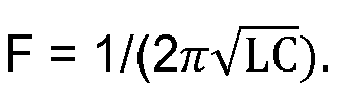
- In
Fig. 1 ,bottom seal 108 may be provided at the bottom surface ofcalibration fixture 100. Optionally, a layer of sand also may be provided immediately above the bottom seal. Additionally,drain cock 110 may be located in the wall of the calibration fixture adjacent the bottom seal and may be used to drain or remove water from the calibration fixture. - In
Fig. 1 , calibration of capacitance-basedmoisture sensor 102 for a particular soil type may include insertingprobe 104 with at least one sensor into the calibration fixture. Sensor frequency output may be obtained for each of several substances including air, water, dry matrix and saturated soil introduced into the calibration fixture. - In
Fig. 1 ,calibration fixture 100 may have a volume of 2 liters. Sensor frequency output may be obtained fromsensor 102 with only air in the calibration fixture, and with only water in the calibration fixture. A known volume of dry matrix of a selected soil type may be introduced into the calibration fixture, and sensor frequency output may be obtained for the dry matrix. The soil may be compacted to a known compaction pressure. - The sensor calibration method may include introducing a known volume of water into the calibration fixture until the soil is completely saturated. The method also may include measuring the volume of water, and determining the volumetric fraction of water, or Wv, added to the calibration fixture to saturate the dry matrix of the selected soil type. For example, if the volume of water added to saturate the dry matrix in the 2 liter calibration fixture was 807 ml, the volumetric water content is .807/2, or Wv = .4035. Sensor frequency output may be obtained for the saturated soil. Optionally,
drain cock 110 then may be opened so that water may drain by gravity out of the fixture, and the volume of drained water may be measured. - The sensor calibration method may include converting each sensor frequency reading, such as frequencies in the range of 100 MHz to 200 MHz, to a scaled frequency value. The highest sensor frequency reading is for air (for example, 161 Mhz) and may be converted to a minimum scaled frequency value of 0.000. The lowest sensor frequency reading is for water (for example, 115 MHz) and may be converted to a maximum scaled frequency value of 1.000. Each of the other sensor frequency readings may be converted to a scaled frequency value between 0.000 and 1.000 by linear interpolation. For example, a sensor frequency reading of 129 MHz for dry matrix may be converted to a scaled frequency value of 0.695, and a sensor frequency reading of 119 MHz for saturated soil may be converted to a scaled frequency value of 0.906. Each scaled frequency value also may be referred to as the normalized response (NR).
- The sensor calibration method may include solving an equation wherein volumetric water content is a function of the sensor frequency response or scaled frequency value for saturated soil, along with one or more fitting constants. For example, one such equation is Wv = ((NR - C)/A)(1/B) and may be solved for one or more fitting constants A, B or C. In this example, Wv is the volumetric fraction of water added to the calibration fixture to saturate the dry matrix, NR is the normalized response for the saturated soil, and A, B and C are fitting constants. In this example, fitting constant B may be based on generalized refractive dielectric models for moist soils at frequencies in a desired range of 100 MHz to 200 MHz. For example, an appropriate value for fitting constant B is 0.450 for most soils in a sensor frequency range of 100 MHz to 200 MHz. Additionally, fitting constant C may be based on the sensor's scaled frequency value for dry matrix of the selected soil type. In this example, C = 0.695. The equation then may be solved for fitting constant A which is the remaining value. In this example, A = 0.040.
- After the method and apparatus of
Fig. 1 is used to determine fitting constants A, B and C for a particular sensor and soil type, the same equation and the same values for fitting constants may be applied to reliably and repeatably determine volumetric water content from the sensor's frequency response for that sensor and soil type. -
Fig. 2 shows a second embodiment ofsensor calibration fixture 200 in which probe 202 is in an inverted position. Capacitance-basedmoisture sensor 204 may be mounted to the internal surface of the probe in direct contact with the inside probe wall.Bottom seal 206 may be provided at or near the bottom surface ofcalibration fixture 200, anddrain cock 208 may be used to drain or remove water from the calibration fixture. The method for the calibration apparatus ofFig. 2 may be substantially the same as for the apparatus ofFig. 1 . -
Fig. 3 shows an embodiment of capacitance-basedmoisture sensor 300 that may be used for testing of soil or other materials for moisture content, characterizing soil types, and/or calibration of sensors for a selected soil type.Sensor 300 may be referred to as an internal sensor because soil or other material may be placed in a container orvessel 310 that is inserted inside a pair of ring-shapedconductive bands 306. The pair of ring-shapedconductive bands 306 form a fringing capacitor positioned around the exterior of hollow cylinder orsleeve 304. - Capacitance-based
moisture sensor 300 shown inFig. 3 may be used to calibrate sensors having the same or substantially the same capacitor dimensions and inductor characteristics. For example, calibration using the apparatus ofFig. 3 may provide the same or substantially the same results as the apparatus ofFig. 1 or Fig. 2 . InFig. 3 , ring-shapedconductive bands 306 may be coupled to the same or similar fixed inductor or oscillator board to form a free running oscillator having the same frequency output and range as those ofFigs. 1 and 2 . As a result, calibration values obtained fromsensor 300 are valid and may be used for capacitance-based moisture sensors mounted in a probe for insertion in soil.Sensor 300 may be significantly smaller in size, faster to operate and less labor intensive than other calibration devices and methods. -
Fig. 3 ,conductive bands 306 may form a fringing capacitor with each band having a preferred diameter of about 2 inches, and a preferred width of between about ½ inch and about 1 inch. The bands may be copper and may be spaced in an axial direction from each other by about ½ inch. The capacitor dimensions may be the same or substantially similar to capacitors in the capacitance-based moisture sensors shown in the probes ofFigs. 1 and 2 . The electric field of the capacitor may extend through the wall of cylinder orsleeve 304 and interact with the substance incontainer 310 to make the value of the capacitor variable. The variable capacitor may be coupled with a fixed inductor (L) onoscillator board 312 to form a free running oscillator with a frequency
microprocessor board 314 which may provide a frequency counter. -
Fig. 3 , cylinder orsleeve 304 may be a one-piece plastic body having an outer diameter of about 2 inches and a length of between about 3 inches and about 6 inches. Cavity orinternal passage 308 may extend at least partially or completely through the sleeve and may have an internal diameter of about 1.75 inches.Container 310 may be a glass or plastic jar dimensioned for insertion into the cavity or passage through the sleeve. The outer circumference ofcontainer 310 may be the same or slightly smaller than the internal circumference ofsleeve 304 so that it has a snug but not tight fit. For example, the volume of the container may be about 250 ml. -
Fig. 3 ,calibration using sensor 300 for a particular soil or other material may include insertingcontainer 310 into the cavity orinternal passage 308 and obtaining sensor frequency output for each of several substances in the container. Sensor frequency output may be obtained with only air in the container, and with only water in the container. A known volume of dry matrix of the soil or other material may be introduced into the container, and sensor output may be obtained for the dry matrix. -
Fig. 3 , water may be added intocontainer 310 until the soil or other material is completely saturated. The volume of water added to the container may be measured, and the volumetric water content Wv may be determined to saturate the dry matrix of the soil or other material. For example, if the volume of water added to saturate the dry matrix in the container was 101 ml, the volumetric water content is 101/250, or Wv = .404. Sensor frequency output may be obtained for the saturated soil or other material. -
Fig. 3 , the sensor calibration method may include converting each sensor frequency reading to a scaled frequency value, using the same method as describe for the embodiments ofFigs. 1 and 2 . - In one embodiment, the sensor calibration method using the apparatus of
Fig. 3 also may include solving an equation where volumetric water content is a function of the sensor frequency response or scaled frequency value for the saturated soil or other material, along with one or more fitting constants. For example, the equation Wv = ((NR - C)/A)(1/B) may be solved for one or more fitting constants A, B or C. In the above equation, Wv is the volumetric fraction of water added to the container to saturate the dry matrix, NR is the normalized response for the saturated soil or other material, and A, B and C are fitting constants. One or more other fitting constants may be included to compensate if there is any slight effect of the walls ofcontainer 310. In the above equation, fitting constant B may be based on generalized refractive dielectric models for moist soils at sensor frequencies in the desired range. For example, fitting constant B may be selected as 0.450 for a sensor frequency range of 100 MHz to 200 MHz. Additionally, fitting constant C may be based on the sensor's scaled frequency reading for the dry matrix for the soil or other material. In this example, C = 0.695. The equation then may be solved for fitting constant A which is the only remaining unknown value. In this example, A = 0.040. Once fitting constants A, B and C are determined for a particular sensor and soil or other material type, the above equation may be used to determine volumetric water content based on the sensor's frequency response for that soil or other material. - The apparatus and method of
Fig. 3 may be used to determine one or more fitting constants for a particular sensor and soil or other material, and the same fitting constants then may be used to reliably and repeatably determine volumetric water content from the sensor's frequency response for that soil or other material. Thus, the apparatus and method ofFig. 3 enables calibration of capacitance-based moisture sensors using a small sample in a container, instead of inserting a probe with a sensor in the ground. - The capacitance-based moisture sensor of
Fig. 3 may be used to measure moisture content of materials other than soil, including but not limited to agricultural products.Sensor 300 may be calibrated for a selected material using the apparatus and method described above. Sensor frequency may be obtained for dry material placed in the container and inserted intosleeve 304, and for the material after saturation with a measured volume of water. Fitting constants may be determined for that material and sensor using the same or similar equation described above. After calibration, the sensor may be used to reliably and repeatably measure moisture content of that material. - The capacitance-based moisture sensor of
Fig. 3 and the corresponding method may be used to characterize soils or other materials. For example, frequency output ofsensor 300, for a dry matrix and/or saturated sample of an unknown soil, may be compared to the sensor's frequency output for one or more known soil types. The frequency output fromsensor 300 may be the same or substantially similar as a known soil type such as sand, sandy loam, loam or clay.
Claims (13)
- A capacitance-based moisture sensor, comprising:a sleeve having an internal cavity;a container inserted into the internal cavity whereas the container is suitable to be filled with soil or other material; anda pair of ring-shaped conductive bands around the exterior of the sleeve forming a capacitor and providing a frequency output.
- The capacitance-based moisture sensor according to claims 1 wherein the frequency output relates to a water content of the soil or the other material.
- The capacitance-based moisture sensor according to one of the claims 1 to 2 wherein the capacitor is coupled to a fixed inductor to form a free-running oscillator.
- The capacitance-based moisture sensor according to one of the claims 1 to 3 wherein the sleeve is a hollow cylindrical plastic body.
- A capacitance-based moisture sensing method, comprising:filling a container having a known volume with a material;inserting the container into a hollow sleeve; andobtaining a frequency output from a pair of ring-shaped conductive rings positioned around a perimeter of the sleeve and connected to a fixed inductor to form an oscillator with a variable frequency output.
- The capacitance-based moisture sensing method of claim 5 further comprising saturating the material with a measured volume of water and obtaining the frequency output for the saturated material.
- The capacitance-based moisture sensing method of claim 5 or 6 further comprising placing water into the container and obtaining the frequency output for water.
- The capacitance-based moisture sensing method according to one of the claims 5 to 7 further comprising placing a dry matrix in the container and obtaining the frequency output for the dry matrix.
- The capacitance-based moisture sensing method according to one of the claims 5 to 8 further comprising characterizing the material by comparing the frequency output from the material to the frequency output of a known material.
- The capacitance-based moisture sensing method according to one of the claims 5 to 9 further comprising calibrating a capacitance-based moisture sensor by obtaining the frequency output for each of a plurality of materials in the container.
- The capacitance-based moisture sensing method according to one of the claims 5 to 10 further comprising determining a volumetric water content as a function of the frequency output.
- The capacitance-based moisture sensing method of claim 11 further comprising calibrating a capacitance-based moisture sensor by using the frequency output to and the volumetric water content to determine at least one fitting constant in an equation where the volumetric water content is a function of the frequency output.
- The capacitance-based moisture sensing method according to one of the claims 5 to 12 further comprising determining a fitting constant A, B or C in an equation Wv = ((NR - C)/A)(1/B) where Wv is a volumetric water content of the saturated soil in the container and NR is a normalized value for the frequency output.
Priority Applications (1)
| Application Number | Priority Date | Filing Date | Title |
|---|---|---|---|
| EP20140168692 EP2784495A1 (en) | 2012-02-03 | 2013-01-31 | Capacitance-based moisture sensor calibration method |
Applications Claiming Priority (1)
| Application Number | Priority Date | Filing Date | Title |
|---|---|---|---|
| US13/365,388 US9146206B2 (en) | 2012-02-03 | 2012-02-03 | Capacitance-based moisture sensor |
Related Child Applications (1)
| Application Number | Title | Priority Date | Filing Date |
|---|---|---|---|
| EP20140168692 Division EP2784495A1 (en) | 2012-02-03 | 2013-01-31 | Capacitance-based moisture sensor calibration method |
Publications (1)
| Publication Number | Publication Date |
|---|---|
| EP2623971A1 true EP2623971A1 (en) | 2013-08-07 |
Family
ID=47665960
Family Applications (2)
| Application Number | Title | Priority Date | Filing Date |
|---|---|---|---|
| EP20140168692 Withdrawn EP2784495A1 (en) | 2012-02-03 | 2013-01-31 | Capacitance-based moisture sensor calibration method |
| EP13153427.3A Withdrawn EP2623971A1 (en) | 2012-02-03 | 2013-01-31 | Capacitance-based moisture sensor |
Family Applications Before (1)
| Application Number | Title | Priority Date | Filing Date |
|---|---|---|---|
| EP20140168692 Withdrawn EP2784495A1 (en) | 2012-02-03 | 2013-01-31 | Capacitance-based moisture sensor calibration method |
Country Status (6)
| Country | Link |
|---|---|
| US (1) | US9146206B2 (en) |
| EP (2) | EP2784495A1 (en) |
| CN (1) | CN103245701A (en) |
| AU (3) | AU2013200510A1 (en) |
| BR (1) | BR102013002485B1 (en) |
| IL (1) | IL224485A (en) |
Families Citing this family (16)
| Publication number | Priority date | Publication date | Assignee | Title |
|---|---|---|---|---|
| GB2531291B (en) * | 2014-10-14 | 2019-12-04 | Aspen Pumps Ltd | Liquid level detector |
| US9949450B2 (en) | 2014-11-03 | 2018-04-24 | MorpH2O Water Management, LLC | Soil moisture probe and system with temperature adjustment |
| CN104950012A (en) * | 2015-07-02 | 2015-09-30 | 水利部南京水利水文自动化研究所 | Integrated adjustable automatic soil longitudinal water recording instrument |
| CN105486729A (en) * | 2016-01-18 | 2016-04-13 | 北京至感传感器技术研究院有限公司 | Humidity sensor |
| CN106248522B (en) * | 2016-07-19 | 2019-06-07 | 西安思坦环境科技有限公司 | A kind of laboratory investment method about soil moisture content sensor |
| CN106970122B (en) * | 2017-05-02 | 2020-07-17 | 中国水利水电科学研究院 | An integrated device for drilling and measuring soil moisture |
| US10597231B2 (en) | 2017-09-14 | 2020-03-24 | Next Tier Agribusiness, Llc | System and method for storing water in an underground reservoir and managing the same |
| US10336544B2 (en) | 2017-09-14 | 2019-07-02 | Next Tier Agribusiness, Llc | System and method for storing water in an underground reservoir and managing the same |
| CN107703193B (en) * | 2017-09-27 | 2020-04-10 | 北京农业智能装备技术研究中心 | Device and method for measuring moisture content in compost |
| IT201800002647A1 (en) * | 2018-02-13 | 2019-08-13 | Univ Degli Studi Di Milano Bicocca | DEVICE AND METHOD FOR SIMULATION OF INJECTIONS OF CEMENTITIOUS AND / OR CHEMICAL MIXTURES IN SOILS |
| CN109596786B (en) * | 2018-12-30 | 2024-07-09 | 武汉景弘生态环境股份有限公司 | Device and method for detecting water content of garbage |
| CN110244024B (en) * | 2019-07-05 | 2022-03-22 | 广州大学 | A sustainable humidity probe |
| US11358796B2 (en) | 2020-02-18 | 2022-06-14 | Next Tier Agribusiness | System and method for storing water in an underground reservoir and managing the same |
| US11434079B2 (en) | 2020-02-18 | 2022-09-06 | Next Tier Agribusiness | System and method for storing water in an underground reservoir and managing the same |
| US12517075B2 (en) * | 2020-08-18 | 2026-01-06 | National University Corporation Kagawa University | Plant water content sensor and plant water content measuring method |
| US12265048B2 (en) * | 2022-11-23 | 2025-04-01 | Globalfoundries U.S. Inc. | Moisture detection along input/output opening in IC structure |
Citations (6)
| Publication number | Priority date | Publication date | Assignee | Title |
|---|---|---|---|---|
| US2373846A (en) * | 1941-08-02 | 1945-04-17 | Olken Hyman | Method and apparatus for moisture measurement of materials |
| US2555977A (en) * | 1950-02-08 | 1951-06-05 | Gen Electric | Moisture content monitor |
| US2724798A (en) * | 1952-01-26 | 1955-11-22 | Beckman Instruments Inc | Apparatus for measuring characteristics of materials |
| US5418466A (en) | 1990-10-12 | 1995-05-23 | Watson; Keith | Moisture and salinity sensor and method of use |
| US20030033862A1 (en) * | 2001-08-20 | 2003-02-20 | Mcelhaney Trent A. | Portable grain moisture meter |
| US7042234B2 (en) | 2002-12-16 | 2006-05-09 | Sentek Pty Ltd | Soil matric potential and salinity measurement apparatus and method of use |
Family Cites Families (8)
| Publication number | Priority date | Publication date | Assignee | Title |
|---|---|---|---|---|
| US3771548A (en) | 1972-11-03 | 1973-11-13 | G Rauchwerger | Capacitive moisture control system having a peak detector |
| US4540936A (en) | 1982-09-07 | 1985-09-10 | Dartmouth College | Soil moisture sensor |
| US5260666A (en) | 1991-09-23 | 1993-11-09 | Troxler Electronic Laboratories, Inc. | Capacitance monitor for soil moisture |
| US5479104A (en) | 1993-09-14 | 1995-12-26 | Vitel, Inc. | Electrical sensor for determining the moisture content of soil |
| AUPR807801A0 (en) | 2001-10-05 | 2001-10-25 | Sentek Pty Ltd | Soil probe insertion arrangement and method of use |
| US7150184B1 (en) * | 2003-08-27 | 2006-12-19 | Phase Dynamics, Inc | Density independent moisture analyzer |
| US20080199359A1 (en) * | 2005-07-04 | 2008-08-21 | Senviro Pty Ltd | Soil Moisture Sensor |
| US7535237B1 (en) | 2008-01-21 | 2009-05-19 | Advanced Sensor Technology, Inc. | Sensor for measuring moisture and salinity |
-
2012
- 2012-02-03 US US13/365,388 patent/US9146206B2/en active Active
-
2013
- 2013-01-30 IL IL224485A patent/IL224485A/en active IP Right Grant
- 2013-01-31 EP EP20140168692 patent/EP2784495A1/en not_active Withdrawn
- 2013-01-31 EP EP13153427.3A patent/EP2623971A1/en not_active Withdrawn
- 2013-01-31 BR BR102013002485-6A patent/BR102013002485B1/en active IP Right Grant
- 2013-01-31 AU AU2013200510A patent/AU2013200510A1/en not_active Abandoned
- 2013-02-04 CN CN2013100442017A patent/CN103245701A/en active Pending
-
2016
- 2016-11-25 AU AU2016262769A patent/AU2016262769A1/en not_active Abandoned
-
2019
- 2019-01-29 AU AU2019200547A patent/AU2019200547A1/en not_active Abandoned
Patent Citations (6)
| Publication number | Priority date | Publication date | Assignee | Title |
|---|---|---|---|---|
| US2373846A (en) * | 1941-08-02 | 1945-04-17 | Olken Hyman | Method and apparatus for moisture measurement of materials |
| US2555977A (en) * | 1950-02-08 | 1951-06-05 | Gen Electric | Moisture content monitor |
| US2724798A (en) * | 1952-01-26 | 1955-11-22 | Beckman Instruments Inc | Apparatus for measuring characteristics of materials |
| US5418466A (en) | 1990-10-12 | 1995-05-23 | Watson; Keith | Moisture and salinity sensor and method of use |
| US20030033862A1 (en) * | 2001-08-20 | 2003-02-20 | Mcelhaney Trent A. | Portable grain moisture meter |
| US7042234B2 (en) | 2002-12-16 | 2006-05-09 | Sentek Pty Ltd | Soil matric potential and salinity measurement apparatus and method of use |
Non-Patent Citations (4)
| Title |
|---|
| "CALIBRATION MANUAL For Sentek Soil Moisture Sensors Version 2.0", 11 October 2011 (2011-10-11), AUSTRALIA, XP055135934, Retrieved from the Internet <URL:www.sentek.com.au> [retrieved on 20140821] * |
| PALTINEANU ANDJ L STARR I C: "Real-time soil water dynamics using multisensor capacitance probes: laboratory calibration", SOIL SCIENCE SOCIETY OF AMERICA. JOURNAL, US, vol. 61, no. 6, 1 January 1997 (1997-01-01), pages 1576 - 1585, XP009179768, ISSN: 0361-5995, DOI: 10.2136/SSSAJ1997.03615995006100060006X * |
| R L BAUMHARDT ET AL: "Soil Material, Temperature, and Salinity Effects on Calibration of Multisensor Capacitance Probes", SOIL SCIENCE SOCIETY OF AMERICA JOURNAL, vol. 64, no. 6, 1 November 2000 (2000-11-01), pages 1940 - 1946, XP055135976, DOI: 10.2136/sssaj2000.6461940x * |
| ROBICHAUD P. R. ET AL: "Measuring duff moisture content in the field using a portable meter sensitive to dielectric permittivity", INTERNATIONAL JOURNAL OFWILDLAND FIRE, vol. 13, no. 3, 16 November 2004 (2004-11-16), pages 543 - 553, XP002695564, DOI: http://dx.doi.org/10.1071/WF03072 * |
Also Published As
| Publication number | Publication date |
|---|---|
| US9146206B2 (en) | 2015-09-29 |
| EP2784495A1 (en) | 2014-10-01 |
| IL224485A (en) | 2017-09-28 |
| CN103245701A (en) | 2013-08-14 |
| AU2013200510A1 (en) | 2013-08-22 |
| AU2016262769A1 (en) | 2016-12-15 |
| BR102013002485B1 (en) | 2020-12-01 |
| AU2019200547A1 (en) | 2019-02-14 |
| BR102013002485A2 (en) | 2013-12-17 |
| US20130200905A1 (en) | 2013-08-08 |
Similar Documents
| Publication | Publication Date | Title |
|---|---|---|
| US9146206B2 (en) | Capacitance-based moisture sensor | |
| Ebrahimi et al. | Microwave microfluidic sensor for determination of glucose concentration in water | |
| Vaz et al. | Evaluation of standard calibration functions for eight electromagnetic soil moisture sensors | |
| Tarantino et al. | Field measurement of suction, water content, and water permeability | |
| Bobrov et al. | Wideband frequency domain method of soil dielectric property measurements | |
| US8947102B1 (en) | Soil water and conductivity sensing system | |
| Yang et al. | Adaptive calibration of a capacitance tomography system for imaging water droplet distribution | |
| US11408835B2 (en) | Microwave soil moisture sensor based on phase shift method and independent of electrical conductivity of the soil | |
| CN109253960B (en) | A Spontaneous Imbibition Measurement Method Based on Capacitive Coupling | |
| Schwank et al. | Laboratory characterization of a commercial capacitance sensor for estimating permittivity and inferring soil water content | |
| WO2012176129A2 (en) | Matrix permittivity determination | |
| Buragohain et al. | Interdigitated capacitor based frequency splitting differential microwave sensor for complete dielectric characterization of organic liquids | |
| CN105675437B (en) | Displacement difference solution density measuring device and its measuring method | |
| US4924173A (en) | Shielded capacitance standard | |
| Vaz et al. | Soil water retention measurements using a combined Tensiometer‐Coiled time domain reflectometry probe | |
| Kammerer et al. | Performance of Hydra Probe and MPS-1 soil water sensors in topsoil tested in lab and field | |
| Chen et al. | Monitoring near-surface soil water content using an innovative perforated cylinder coaxial dielectric sensor | |
| RU2433393C1 (en) | Device for measuring soil moisture | |
| Huang et al. | Microwave sensor for measuring the properties of a liquid drop | |
| Ebrahimi et al. | Highly sensitive microwave-based biosensor for electrolytic level measurement in water | |
| Brahma et al. | Electrical methods of soil moisture measurement: a review | |
| RU159796U1 (en) | DEVICE FOR DETERMINING SOIL HUMIDITY | |
| Bello et al. | Investigation of temperature effects and performance evaluation of a newly developed capacitance probe | |
| Bodasingi et al. | Evaluation of a Low-Cost Soil Moisture and EC Sensor in Different Soil Types | |
| Narayanan et al. | Laboratory calibration of capacitance-based soil moisture sensor to monitor subsurface soil moisture movement in laterite soil |
Legal Events
| Date | Code | Title | Description |
|---|---|---|---|
| PUAI | Public reference made under article 153(3) epc to a published international application that has entered the european phase |
Free format text: ORIGINAL CODE: 0009012 |
|
| AK | Designated contracting states |
Kind code of ref document: A1 Designated state(s): AL AT BE BG CH CY CZ DE DK EE ES FI FR GB GR HR HU IE IS IT LI LT LU LV MC MK MT NL NO PL PT RO RS SE SI SK SM TR |
|
| AX | Request for extension of the european patent |
Extension state: BA ME |
|
| 17P | Request for examination filed |
Effective date: 20140207 |
|
| RBV | Designated contracting states (corrected) |
Designated state(s): AL AT BE BG CH CY CZ DE DK EE ES FI FR GB GR HR HU IE IS IT LI LT LU LV MC MK MT NL NO PL PT RO RS SE SI SK SM TR |
|
| RIN1 | Information on inventor provided before grant (corrected) |
Inventor name: HENDRICKSON, LARRY Inventor name: MORTON, CLAYTON S. Inventor name: RHODES, MICHAEL L. Inventor name: CHAMBERS, JAMES A. Inventor name: JARVIS, GRAEME L. |
|
| 17Q | First examination report despatched |
Effective date: 20140828 |
|
| STAA | Information on the status of an ep patent application or granted ep patent |
Free format text: STATUS: THE APPLICATION HAS BEEN WITHDRAWN |
|
| 18W | Application withdrawn |
Effective date: 20140516 |