EP2623833A1 - Connecting device for the fluid-tight connection between two pipes in an internal combustion engine - Google Patents
Connecting device for the fluid-tight connection between two pipes in an internal combustion engine Download PDFInfo
- Publication number
- EP2623833A1 EP2623833A1 EP20130152943 EP13152943A EP2623833A1 EP 2623833 A1 EP2623833 A1 EP 2623833A1 EP 20130152943 EP20130152943 EP 20130152943 EP 13152943 A EP13152943 A EP 13152943A EP 2623833 A1 EP2623833 A1 EP 2623833A1
- Authority
- EP
- European Patent Office
- Prior art keywords
- connector
- connection terminal
- electrical connection
- electrical connector
- suited
- Prior art date
- Legal status (The legal status is an assumption and is not a legal conclusion. Google has not performed a legal analysis and makes no representation as to the accuracy of the status listed.)
- Withdrawn
Links
- 238000002485 combustion reaction Methods 0.000 title description 12
- 230000008878 coupling Effects 0.000 claims description 23
- 238000010168 coupling process Methods 0.000 claims description 23
- 238000005859 coupling reaction Methods 0.000 claims description 23
- 239000004020 conductor Substances 0.000 claims description 7
- 230000003134 recirculating effect Effects 0.000 description 4
- 230000009471 action Effects 0.000 description 2
- 238000003915 air pollution Methods 0.000 description 2
- 238000004140 cleaning Methods 0.000 description 2
- 230000000694 effects Effects 0.000 description 2
- 230000004075 alteration Effects 0.000 description 1
- 230000008859 change Effects 0.000 description 1
- 239000007789 gas Substances 0.000 description 1
- 238000005461 lubrication Methods 0.000 description 1
- 239000002184 metal Substances 0.000 description 1
- 238000011084 recovery Methods 0.000 description 1
Images

Classifications
-
- H—ELECTRICITY
- H01—ELECTRIC ELEMENTS
- H01R—ELECTRICALLY-CONDUCTIVE CONNECTIONS; STRUCTURAL ASSOCIATIONS OF A PLURALITY OF MUTUALLY-INSULATED ELECTRICAL CONNECTING ELEMENTS; COUPLING DEVICES; CURRENT COLLECTORS
- H01R13/00—Details of coupling devices of the kinds covered by groups H01R12/70 or H01R24/00 - H01R33/00
- H01R13/62—Means for facilitating engagement or disengagement of coupling parts or for holding them in engagement
-
- F—MECHANICAL ENGINEERING; LIGHTING; HEATING; WEAPONS; BLASTING
- F16—ENGINEERING ELEMENTS AND UNITS; GENERAL MEASURES FOR PRODUCING AND MAINTAINING EFFECTIVE FUNCTIONING OF MACHINES OR INSTALLATIONS; THERMAL INSULATION IN GENERAL
- F16L—PIPES; JOINTS OR FITTINGS FOR PIPES; SUPPORTS FOR PIPES, CABLES OR PROTECTIVE TUBING; MEANS FOR THERMAL INSULATION IN GENERAL
- F16L25/00—Construction or details of pipe joints not provided for in, or of interest apart from, groups F16L13/00 - F16L23/00
- F16L25/01—Construction or details of pipe joints not provided for in, or of interest apart from, groups F16L13/00 - F16L23/00 specially adapted for realising electrical conduction between the two pipe ends of the joint or between parts thereof
-
- F—MECHANICAL ENGINEERING; LIGHTING; HEATING; WEAPONS; BLASTING
- F16—ENGINEERING ELEMENTS AND UNITS; GENERAL MEASURES FOR PRODUCING AND MAINTAINING EFFECTIVE FUNCTIONING OF MACHINES OR INSTALLATIONS; THERMAL INSULATION IN GENERAL
- F16L—PIPES; JOINTS OR FITTINGS FOR PIPES; SUPPORTS FOR PIPES, CABLES OR PROTECTIVE TUBING; MEANS FOR THERMAL INSULATION IN GENERAL
- F16L37/00—Couplings of the quick-acting type
- F16L37/08—Couplings of the quick-acting type in which the connection between abutting or axially overlapping ends is maintained by locking members
- F16L37/084—Couplings of the quick-acting type in which the connection between abutting or axially overlapping ends is maintained by locking members combined with automatic locking
- F16L37/098—Couplings of the quick-acting type in which the connection between abutting or axially overlapping ends is maintained by locking members combined with automatic locking by means of flexible hooks
-
- H—ELECTRICITY
- H01—ELECTRIC ELEMENTS
- H01R—ELECTRICALLY-CONDUCTIVE CONNECTIONS; STRUCTURAL ASSOCIATIONS OF A PLURALITY OF MUTUALLY-INSULATED ELECTRICAL CONNECTING ELEMENTS; COUPLING DEVICES; CURRENT COLLECTORS
- H01R13/00—Details of coupling devices of the kinds covered by groups H01R12/70 or H01R24/00 - H01R33/00
- H01R13/005—Electrical coupling combined with fluidic coupling
-
- H—ELECTRICITY
- H01—ELECTRIC ELEMENTS
- H01R—ELECTRICALLY-CONDUCTIVE CONNECTIONS; STRUCTURAL ASSOCIATIONS OF A PLURALITY OF MUTUALLY-INSULATED ELECTRICAL CONNECTING ELEMENTS; COUPLING DEVICES; CURRENT COLLECTORS
- H01R13/00—Details of coupling devices of the kinds covered by groups H01R12/70 or H01R24/00 - H01R33/00
- H01R13/64—Means for preventing incorrect coupling
-
- F—MECHANICAL ENGINEERING; LIGHTING; HEATING; WEAPONS; BLASTING
- F01—MACHINES OR ENGINES IN GENERAL; ENGINE PLANTS IN GENERAL; STEAM ENGINES
- F01M—LUBRICATING OF MACHINES OR ENGINES IN GENERAL; LUBRICATING INTERNAL COMBUSTION ENGINES; CRANKCASE VENTILATING
- F01M13/00—Crankcase ventilating or breathing
-
- F—MECHANICAL ENGINEERING; LIGHTING; HEATING; WEAPONS; BLASTING
- F02—COMBUSTION ENGINES; HOT-GAS OR COMBUSTION-PRODUCT ENGINE PLANTS
- F02M—SUPPLYING COMBUSTION ENGINES IN GENERAL WITH COMBUSTIBLE MIXTURES OR CONSTITUENTS THEREOF
- F02M25/00—Engine-pertinent apparatus for adding non-fuel substances or small quantities of secondary fuel to combustion-air, main fuel or fuel-air mixture
- F02M25/06—Engine-pertinent apparatus for adding non-fuel substances or small quantities of secondary fuel to combustion-air, main fuel or fuel-air mixture adding lubricant vapours
-
- F—MECHANICAL ENGINEERING; LIGHTING; HEATING; WEAPONS; BLASTING
- F16—ENGINEERING ELEMENTS AND UNITS; GENERAL MEASURES FOR PRODUCING AND MAINTAINING EFFECTIVE FUNCTIONING OF MACHINES OR INSTALLATIONS; THERMAL INSULATION IN GENERAL
- F16L—PIPES; JOINTS OR FITTINGS FOR PIPES; SUPPORTS FOR PIPES, CABLES OR PROTECTIVE TUBING; MEANS FOR THERMAL INSULATION IN GENERAL
- F16L2201/00—Special arrangements for pipe couplings
- F16L2201/10—Indicators for correct coupling
-
- F—MECHANICAL ENGINEERING; LIGHTING; HEATING; WEAPONS; BLASTING
- F16—ENGINEERING ELEMENTS AND UNITS; GENERAL MEASURES FOR PRODUCING AND MAINTAINING EFFECTIVE FUNCTIONING OF MACHINES OR INSTALLATIONS; THERMAL INSULATION IN GENERAL
- F16N—LUBRICATING
- F16N21/00—Conduits; Junctions; Fittings for lubrication apertures
Definitions
- the present invention relates to a connecting device for the fluid-tight connection between two pipes of an internal combustion engine.
- Vapors are normally produced in an internal combustion engine, in the heads and/or in the oil tank during the running of the engine itself; air pollution control regulations prohibit exhaust of such vapor into the atmosphere and require that they be fed into the cylinders for controlled combustion thereof.
- an internal combustion engine is provided with a recirculating circuit which is provided with a feed duct originating from the engine head or from the oil tank and connected to an intake duct of the engine.
- the feed duct may be disconnected from the feed duct and/or engine head for cleaning or replacement or simply to permit easy access to other parts of the engine.
- the feed duct Once disconnected from the feed duct and/or engine head, the feed duct may be reconnected poorly due to carelessness on the part of the fitter; such a situation easily goes undetected, by the vapors being released directly into the atmosphere and in no way impairing operation of the engine. For such reason, more recent air pollution regulations require correct connection control of the feed duct and that the driver be alerted of any faulty connection.
- each one of such connecting devices comprises a pneumatic connector for pneumatically connecting the feed duct to the intake duct or engine head, and an electrical connector.
- Each connecting device is designed so that the relative pneumatic connector is only connected to a corresponding pneumatic connector on the intake duct or engine head when the relative electrical connector is connected to a corresponding electrical connector on the intake duct or engine head; controlling the electrical continuity of the circuit formed by the mutual coupling of the electrical connectors it is possible to check whether the pneumatic connectors are correctly coupled to each other and thereby, it is possible to check the correct connection of the feed duct.
- connection system described in US Patent 6,532,931-B1 has some drawbacks in that it employs connecting devices comprising a pneumatic connector and an electrical connector in the same structure, which makes the proper cleaning of the pneumatic connector problematic; moreover, any change in the diameter of the pneumatic connector involves high-cost alteration of the connecting device as a whole.
- patent application WO-A1-2004113711 describes a connecting system for the fluid-tight connection between an intake duct and a feed duct which comprises a connecting device, which is adapted to establish a fluid-tight joint between the two ducts and is provided with a fixed electrical connector, a mobile electrical connector, which is mechanically independent of the connecting device and of the second duct and is adapted to couple to the fixed electrical connector.
- the connecting system also comprises an interlocking device, preferably consisting of elastic spring means, which is adapted to allow the fixed electrical connector and the mobile electrical connector to be coupled to each other, only when there is a fluid-tight joint between the two ducts.
- the object of the present invention is to provide a connecting device for the fluid-tight connection between two ducts which is easy and inexpensive to make and at the same time is free from the above-described drawbacks.
- a connecting device is provided for the fluid-tight connection of two pipes of an internal combustion engine according to what claimed in claim 1 and, preferably, in any one of the subsequent claims either directly or indirectly depending on claim 1.
- reference numeral 1 globally indicates an internal combustion engine provided with a number of intake ducts 2; each of which ends in a corresponding intake manifold 3, which is fixed to the top of a respective cylinder head 4.
- the internal combustion engine 1 has a lubrication oil tank 5.
- Engine 1 further comprises a recirculating circuit 6, which is adapted to capture the vapors formed into heads 4 and into the oil tank 5 for introducing such vapors into the intake manifolds 2 so as to determine the controlled combustion thereof inside the cylinders.
- a recirculating circuit 6 which is adapted to capture the vapors formed into heads 4 and into the oil tank 5 for introducing such vapors into the intake manifolds 2 so as to determine the controlled combustion thereof inside the cylinders.
- the recirculating circuit 6 comprises a pair of recovery ducts 7, which are connected to heads 4 for capturing the vapors formed into heads 4 and are connected by a T-shaped joint for leading together into the oil tank 5; and a feed duct 11 which directly draws into the oil tank 5, splits into two feed ducts 11 by means of a T-shaped joint to lead into the intake ducts 2 in the proximity of the intake manifolds 3 and downstream of the throttle valves (not shown in detail).
- Each feed duct 11 is connected to the respective intake duct 2 by means of a respective connecting device 12.
- the connecting devices 12 are connected to a common control unit 13 which is suited to check the correct connection of each feed duct 11 to the respective intake duct 2 and for alerting the driver of a possible faulty connection of a feed duct 11.
- the internal combustion engine 1 comprises a number of connecting devices 12, equal to each other and independent of each other, only one of which will be described hereinafter.
- the connecting device 12 comprises a connector 14, which is suited for the connection in use to the intake duct 2 by means of fixing means (of the known type and not shown).
- Connector 14 comprises a fixed electrical connection terminal 15 and a seat 16 having a tubular shape and provided with an axis X 1 , which is suited to accommodate, in use, a tubular side end 17* of an intermediate connecting body 17.
- An annular body (not shown) is provided on the feed duct 11, provided with a central through hole, coaxial to axis X 1 and adapted to define a seat for receiving a further tubular side end 17** of the intermediate connecting body 17, also coaxial to axis X 1 .
- the intermediate connecting body 17 is therefore connected, in use, to an end of the feed duct 11 for defining a tubular passage duct coaxial to axis X 1 and for establishing a fluid-tight joint between the intake duct 2 and the feed duct 11.
- the connecting device 12 also comprises a mobile electrical connector 18 which is mechanically independent of both the intake duct 2 and the feed duct 11.
- the mobile electrical connector 18 is electrically connected to the common control unit 13 by means of a bipolar electrical conductor 19.
- the mobile electrical connector 18 is further mechanically independent of and separated from connector 14.
- the mobile electrical connector 18 is suited to couple in use to the intermediate connecting body 17.
- the intermediate connecting body 17 is suited to interpose, in use, between the fixed electrical connection terminal 15 and the mobile electrical connector 18 and is suited to allow the fixed electrical connection terminal 15 and the mobile electrical connector 18 to be coupled to each other only when the feed duct 11 is regularly connected to connector 14.
- the intermediate connecting body 17 comprises a bottom end 20 suited for the fixing to connector 14, a central portion 21 and a top end 22.
- the central portion 21 is defined by the two tubular side ends 17, 17** which in turn define the passage duct having a tubular shape and coaxial to axis X 1 and adapted to establish a hydraulic communication between the intake duct 2 and the feed duct 11.
- the tubular side end 17* is fitted into seat 16 of connector 14 whereas the tubular side end 17** is suited for the coupling to the feed duct 11.
- the top end 22 comprises two projecting appendages indicated with reference numerals 23 and 24, respectively.
- appendage 23 is directly facing the fixed electrical connection terminal 15 whereas appendage 24 is directly fixing the bipolar electrical connector 18.
- the two appendages 23 and 24 define an electrical connection between the fixed electrical connection terminal 15 and the mobile electrical connector 18. Appendage 23 is therefore suited to couple to the fixed electrical connection terminal 15 whereas appendage 24 is suited to couple to the mobile electrical connector 18.
- the fixed electrical connection terminal 15 and the mobile electrical connector 18 are suited to establish an electrical continuity between the respective conductor bodies (not shown in detail), once the mutual coupling has been carried out with the interposition of the conductor bodies (shown in figure 4 ) of the intermediate connecting body 17.
- the control unit 13 determines the existence of an electrical continuity between the two conductors of the bipolar electrical conductor 19, then the mobile electrical connector 18 is coupled to the fixed electrical connection terminal 15, which short-circuits the conductor bodies (not shown in detail) of the same mobile electrical connector 18.
- Device 12 is made so as to mechanically prevent the connection between the fixed electrical connection terminal 15 and the mobile electrical connector 18 when the feed duct 11 is disconnected from connector 14.
- a result is achieved by the particular shape of the grooves and of the coupling elements of the intermediate connecting body 17 with the mobile electrical connector 18 and with the fixed electrical connection terminal 15, respectively.
- the fixed electrical connection terminal 15 has a male connector element 25 which extends from a top wall 26 and is suited to couple to a coupling groove 27 obtained in appendage 23 directly facing the same fixed electrical connection terminal 15.
- appendage 24 directly facing the mobile electrical connector 18 has a male connector element 28 which extends from a top wall 29* and is suited to couple to a coupling groove 29 obtained in the mobile electrical connector 18 itself.
- the two male connector elements indicated with reference numerals 25 and 28, respectively (and accordingly the respective coupling grooves 27, 29) have different dimensions.
- the connector element 25 has a plan width different (in particular, larger) from the plan width of the connector element 28.
- the connector element 25 has a section thickness different from the thickness of the connector element 28.
- the connector element 25 has both a plan width and a thickness different from the thickness of the connector element 28.
- the connector element 25 and the connector element 28 have different shapes.
- the intermediate connecting body 17 allows the connection between the fixed electrical connection terminal 15 and the electrical connector 18 while the same connection is mechanically prevented, in the absence of the intermediate connecting body 17, by the male connector elements 25, 28 and by the respective coupling grooves 27, 29.
- appendage 24 has two wedges 30 (only one of wedges 30 is shown in figures 2 to 4 ), which extend outwards from respective side walls 31 and are adapted to engage in use two respective through holes 32 obtained in the side walls of the mobile electrical connector 18.
- the coupling between wedges 30 and the through holes 32 allows the coupling of the mobile electrical connector 18 to the intermediate connecting body 17 to be made steadier.
- the wedges are arranged on appendage 23 and the through holes are obtained in the side walls of the fixed electrical connection terminal 15 for locking the intermediate connecting body 17 to the same fixed electrical connection terminal 15.
- an elastic fixing means 33 is further provided for locking the mobile electrical connector 18 to the intermediate connecting body 17 defined by a U-shaped metal body.
- connector 14 of the connecting device 12 is integral to the feed duct 11 and in particular, it is co-molded with the feed duct 11 so as to be non-separable from the feed duct 11 itself. Moreover, connector 14 is adapted to couple to the respective intake duct 2 for establishing a fluid-tight joint between the intake duct 2 and the feed duct 11.
- the fluid-tight connecting device 12 between two ducts described thus far has some advantages. Firstly, it is easy and inexpensive to make and secondly, it is not possible to tamper the same connecting device 12 to allow the mobile electrical connector 18 and the fixed electrical connector 15 to be coupled to each other when the feed duct 11 is not correctly inserted into the dedicated seat 16 of connector 14.
Landscapes
- Engineering & Computer Science (AREA)
- General Engineering & Computer Science (AREA)
- Mechanical Engineering (AREA)
- Quick-Acting Or Multi-Walled Pipe Joints (AREA)
- Lubrication Of Internal Combustion Engines (AREA)
- Lubrication Details And Ventilation Of Internal Combustion Engines (AREA)
Abstract
A connecting device (12) for the fluid-tight connection of a first and a second duct (2, 11) provided with a connector (14) having a fixed electrical connection terminal (15); a mobile electrical connector (18) for establishing an electrical connection with the fixed electrical connection terminal (15); a control unit (13) suited to check the presence of a connection between the fixed electrical connection terminal (15) and the mobile electrical connector; and an intermediate connecting body (17) interposed in use between the connector (14) and the mobile electrical connector (18), suited to establish an electrical connection between the fixed electrical connection terminal (15) and the mobile electrical connector (18) and suited to allow the fixed electrical connection terminal (15) and the mobile electrical connector (18) to be coupled to each other, only when there is a fluid-tight joint between the two ducts (2, 11).
Description
- The present invention relates to a connecting device for the fluid-tight connection between two pipes of an internal combustion engine.
- Vapors (normally known by the name "blow-by gases") are normally produced in an internal combustion engine, in the heads and/or in the oil tank during the running of the engine itself; air pollution control regulations prohibit exhaust of such vapor into the atmosphere and require that they be fed into the cylinders for controlled combustion thereof. For such reason, an internal combustion engine is provided with a recirculating circuit which is provided with a feed duct originating from the engine head or from the oil tank and connected to an intake duct of the engine.
- During routine servicing of the engine, the feed duct may be disconnected from the feed duct and/or engine head for cleaning or replacement or simply to permit easy access to other parts of the engine. Once disconnected from the feed duct and/or engine head, the feed duct may be reconnected poorly due to carelessness on the part of the fitter; such a situation easily goes undetected, by the vapors being released directly into the atmosphere and in no way impairing operation of the engine. For such reason, more recent air pollution regulations require correct connection control of the feed duct and that the driver be alerted of any faulty connection.
- One solution to determine the correct connection of the feed duct is described in
US-6,532,931-B1 , in which the feed duct is provided on the ends with connecting devices; each one of such connecting devices comprises a pneumatic connector for pneumatically connecting the feed duct to the intake duct or engine head, and an electrical connector. Each connecting device is designed so that the relative pneumatic connector is only connected to a corresponding pneumatic connector on the intake duct or engine head when the relative electrical connector is connected to a corresponding electrical connector on the intake duct or engine head; controlling the electrical continuity of the circuit formed by the mutual coupling of the electrical connectors it is possible to check whether the pneumatic connectors are correctly coupled to each other and thereby, it is possible to check the correct connection of the feed duct. - The connection system described in
US Patent 6,532,931-B1 , however, has some drawbacks in that it employs connecting devices comprising a pneumatic connector and an electrical connector in the same structure, which makes the proper cleaning of the pneumatic connector problematic; moreover, any change in the diameter of the pneumatic connector involves high-cost alteration of the connecting device as a whole. - On the other hand, patent application
WO-A1-2004113711 describes a connecting system for the fluid-tight connection between an intake duct and a feed duct which comprises a connecting device, which is adapted to establish a fluid-tight joint between the two ducts and is provided with a fixed electrical connector, a mobile electrical connector, which is mechanically independent of the connecting device and of the second duct and is adapted to couple to the fixed electrical connector. The connecting system also comprises an interlocking device, preferably consisting of elastic spring means, which is adapted to allow the fixed electrical connector and the mobile electrical connector to be coupled to each other, only when there is a fluid-tight joint between the two ducts. - In other words, if the feed duct is not correctly inserted into the dedicated seat of the connecting device, i.e. if there is no fluid-tight joint between the intake duct and the feed duct, the mobile electrical connector cannot be coupled to the fixed electrical connector by the effect of the action of the interlocking device.
- However, also the fluid-tight connecting system described in
WO-A1-2004113711 has some drawbacks. In fact, it has been determined that the interlocking device may be tampered to allow the mobile electrical connector and the fixed electrical connector to be coupled to each other also when the feed duct is not correctly inserted into the dedicated seat of the connecting device. - The object of the present invention is to provide a connecting device for the fluid-tight connection between two ducts which is easy and inexpensive to make and at the same time is free from the above-described drawbacks.
- According to the present invention, a connecting device is provided for the fluid-tight connection of two pipes of an internal combustion engine according to what claimed in claim 1 and, preferably, in any one of the subsequent claims either directly or indirectly depending on claim 1.
- The present invention will now be described with reference to the accompanying drawings, which illustrate a non-limiting example thereof, in which:
-
figure 1 shows a schematic view of an internal combustion engine with a recirculating circuit provided with a device for the fluid-tight connection between two pipes made according to the present invention; -
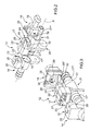
figure 2 shows a perspective, partially exploded view of a connecting device offigure 1 ; -
figure 3 shows a perspective, enlarged scale view of a portion of the connecting device offigure 2 ; and -
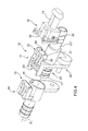
figure 4 shows a perspective, partially exploded view with removed parts for clarity purpose, of the connecting device offigure 2 . - In
figure 1 , reference numeral 1 globally indicates an internal combustion engine provided with a number ofintake ducts 2; each of which ends in acorresponding intake manifold 3, which is fixed to the top of arespective cylinder head 4. The internal combustion engine 1 has alubrication oil tank 5. - Engine 1 further comprises a
recirculating circuit 6, which is adapted to capture the vapors formed intoheads 4 and into theoil tank 5 for introducing such vapors into theintake manifolds 2 so as to determine the controlled combustion thereof inside the cylinders. - The
recirculating circuit 6 comprises a pair of recovery ducts 7, which are connected toheads 4 for capturing the vapors formed intoheads 4 and are connected by a T-shaped joint for leading together into theoil tank 5; and afeed duct 11 which directly draws into theoil tank 5, splits into twofeed ducts 11 by means of a T-shaped joint to lead into theintake ducts 2 in the proximity of theintake manifolds 3 and downstream of the throttle valves (not shown in detail). Eachfeed duct 11 is connected to therespective intake duct 2 by means of a respective connectingdevice 12. The connectingdevices 12 are connected to acommon control unit 13 which is suited to check the correct connection of eachfeed duct 11 to therespective intake duct 2 and for alerting the driver of a possible faulty connection of afeed duct 11. - The internal combustion engine 1 comprises a number of connecting
devices 12, equal to each other and independent of each other, only one of which will be described hereinafter. - According to what shown in
figures 2 and 3 , the connectingdevice 12 comprises aconnector 14, which is suited for the connection in use to theintake duct 2 by means of fixing means (of the known type and not shown). -
Connector 14 comprises a fixedelectrical connection terminal 15 and aseat 16 having a tubular shape and provided with an axis X1, which is suited to accommodate, in use, atubular side end 17* of an intermediate connectingbody 17. An annular body (not shown) is provided on thefeed duct 11, provided with a central through hole, coaxial to axis X1 and adapted to define a seat for receiving a furthertubular side end 17** of the intermediate connectingbody 17, also coaxial to axis X1. - The intermediate connecting
body 17 is therefore connected, in use, to an end of thefeed duct 11 for defining a tubular passage duct coaxial to axis X1 and for establishing a fluid-tight joint between theintake duct 2 and thefeed duct 11. - The connecting
device 12 also comprises a mobileelectrical connector 18 which is mechanically independent of both theintake duct 2 and thefeed duct 11. The mobileelectrical connector 18 is electrically connected to thecommon control unit 13 by means of a bipolarelectrical conductor 19. The mobileelectrical connector 18 is further mechanically independent of and separated fromconnector 14. - The mobile
electrical connector 18 is suited to couple in use to the intermediate connectingbody 17. - In particular, the intermediate connecting
body 17 is suited to interpose, in use, between the fixedelectrical connection terminal 15 and the mobileelectrical connector 18 and is suited to allow the fixedelectrical connection terminal 15 and the mobileelectrical connector 18 to be coupled to each other only when thefeed duct 11 is regularly connected toconnector 14. - In other words, if the intermediate connecting
body 17 is not correctly inserted intoseat 16 ofconnector 14, i.e. if there is not a perfect fluid-tight joint between theintake duct 2 and thefeed duct 11, the mobileelectrical connector 18 cannot be coupled to the fixedelectrical connection terminal 15. This is made possible by the action of the intermediate connectingbody 17. - The intermediate connecting
body 17 comprises abottom end 20 suited for the fixing toconnector 14, acentral portion 21 and atop end 22. Thecentral portion 21 is defined by the twotubular side ends intake duct 2 and thefeed duct 11. In fact, thetubular side end 17* is fitted intoseat 16 ofconnector 14 whereas thetubular side end 17** is suited for the coupling to thefeed duct 11. - The
top end 22 comprises two projecting appendages indicated withreference numerals figure 2 , in a step before assembly,appendage 23 is directly facing the fixedelectrical connection terminal 15 whereasappendage 24 is directly fixing the bipolarelectrical connector 18. The twoappendages electrical connection terminal 15 and the mobileelectrical connector 18.Appendage 23 is therefore suited to couple to the fixedelectrical connection terminal 15 whereasappendage 24 is suited to couple to the mobileelectrical connector 18. - The fixed
electrical connection terminal 15 and the mobileelectrical connector 18 are suited to establish an electrical continuity between the respective conductor bodies (not shown in detail), once the mutual coupling has been carried out with the interposition of the conductor bodies (shown infigure 4 ) of the intermediate connectingbody 17. - When the
control unit 13 determines the existence of an electrical continuity between the two conductors of the bipolarelectrical conductor 19, then the mobileelectrical connector 18 is coupled to the fixedelectrical connection terminal 15, which short-circuits the conductor bodies (not shown in detail) of the same mobileelectrical connector 18. - For the mobile
electrical connector 18 to be coupled to the fixedelectrical connection terminal 15 it is necessary that the intermediate connectingbody 17 be correctly inserted intoseat 16 ofconnector 14; i.e. there must be a fluid-tight joint between theintake duct 2 and thefeed duct 11. From what described above it is clear that thecontrol unit 13 can determine the correct connection of thefeed duct 11 to therespective intake duct 2. -
Device 12 is made so as to mechanically prevent the connection between the fixedelectrical connection terminal 15 and the mobileelectrical connector 18 when thefeed duct 11 is disconnected fromconnector 14. In particular, such a result is achieved by the particular shape of the grooves and of the coupling elements of the intermediate connectingbody 17 with the mobileelectrical connector 18 and with the fixedelectrical connection terminal 15, respectively. - In fact, the fixed
electrical connection terminal 15 has amale connector element 25 which extends from atop wall 26 and is suited to couple to acoupling groove 27 obtained inappendage 23 directly facing the same fixedelectrical connection terminal 15. - Likewise,
appendage 24 directly facing the mobileelectrical connector 18 has amale connector element 28 which extends from atop wall 29* and is suited to couple to acoupling groove 29 obtained in the mobileelectrical connector 18 itself. - It should be noted that the two male connector elements, indicated with
reference numerals respective coupling grooves 27, 29) have different dimensions. In particular, according to the variant shown infigures 2 to 4 , theconnector element 25 has a plan width different (in particular, larger) from the plan width of theconnector element 28. According to a variant not shown, theconnector element 25 has a section thickness different from the thickness of theconnector element 28. - According to a further variant not shown, the
connector element 25 has both a plan width and a thickness different from the thickness of theconnector element 28. - According to a further variant not shown, the
connector element 25 and theconnector element 28 have different shapes. - In this way it is clear that, by the effect of the different dimensions of the
male connector elements respective coupling grooves electrical connector 18 cannot be directly coupled toconnector 14. That is to say, the shape of themale connector elements respective coupling grooves electrical connector 18 from directly coupling to the fixedelectrical connection terminal 15. - The intermediate connecting
body 17 allows the connection between the fixedelectrical connection terminal 15 and theelectrical connector 18 while the same connection is mechanically prevented, in the absence of the intermediate connectingbody 17, by themale connector elements respective coupling grooves - Moreover,
appendage 24 has two wedges 30 (only one ofwedges 30 is shown infigures 2 to 4 ), which extend outwards fromrespective side walls 31 and are adapted to engage in use two respective throughholes 32 obtained in the side walls of the mobileelectrical connector 18. The coupling betweenwedges 30 and the throughholes 32 allows the coupling of the mobileelectrical connector 18 to the intermediate connectingbody 17 to be made steadier. - According to a further variant, the wedges are arranged on
appendage 23 and the through holes are obtained in the side walls of the fixedelectrical connection terminal 15 for locking the intermediate connectingbody 17 to the same fixedelectrical connection terminal 15. - According to a preferred embodiment, an elastic fixing means 33 is further provided for locking the mobile
electrical connector 18 to the intermediate connectingbody 17 defined by a U-shaped metal body. - According to an alternative embodiment,
connector 14 of the connectingdevice 12 is integral to thefeed duct 11 and in particular, it is co-molded with thefeed duct 11 so as to be non-separable from thefeed duct 11 itself. Moreover,connector 14 is adapted to couple to therespective intake duct 2 for establishing a fluid-tight joint between theintake duct 2 and thefeed duct 11. - The above description explicitly refers to the connection between the
intake duct 2 and thefeed duct 11 but it may find advantageous application in the fluid-tight connection of any duct in an internal combustion engine without loss of generality. - The fluid-tight connecting
device 12 between two ducts described thus far has some advantages. Firstly, it is easy and inexpensive to make and secondly, it is not possible to tamper the same connectingdevice 12 to allow the mobileelectrical connector 18 and the fixedelectrical connector 15 to be coupled to each other when thefeed duct 11 is not correctly inserted into thededicated seat 16 ofconnector 14.
Claims (8)
- A connecting device (12) for the fluid-tight connection of a first and a second duct (2, 11); the connecting device (12) comprises:a connector (14), which is suited to establish a fluid-tight joint between said two ducts (2, 11) and is provided with a fixed electrical connection terminal (15);a mobile electrical connector (18), which is mechanically independent of the first and the second duct (2, 11) and, furthermore, is mechanically separated from and independent of the connector (14) and is suited to establish an electrical connection with the fixed electrical connection terminal (15);a control unit (13), which is suited to check the presence of a connection between the fixed electrical connection terminal (15) and the mobile electrical connector (18); andan intermediate connecting body (17), which is interposed between the connector (14) and the mobile electrical connector (18), is suited to establish an electrical connection with both the fixed electrical connection terminal (15) and the mobile electrical connector (18), and is adapted to allow the fixed electrical connection terminal (15) and the mobile electrical connector (18) to be coupled to each other, only when there is a fluid-tight joint between the two ducts (2, 11);the connecting device (12) is characterized in that it comprises coupling means (25, 27; 28, 29) for coupling the intermediate connecting body (17) to the fixed electrical connection terminal (15) and to the mobile electrical connector (18) respectively; the coupling means (25, 27; 28, 29) being manufactured so as to mechanically prevent the fixed electrical connection terminal (15) and the mobile electrical connector (18) from being connected, when there is no fluid-tight joint between the two ducts (2, 11).
- A connecting device according to claim 1, wherein the fixed electrical connection terminal (15), the mobile electrical connector (18), and the intermediate connecting body (17) all comprise bipolar electrical connectors, which are suited to establish an electrical continuity between the respective conductor bodies, once the mutual coupling has been carried out.
- A connecting device according to claim 1 or 2, wherein the coupling means (25, 27) for coupling the intermediate connecting body (17) to the fixed electrical connection terminal (15) present shapes and/or sizes that are different from those of the coupling means (28, 29) for coupling the intermediate connecting body (17) to the mobile electrical connector (18).
- A device according to one of the preceding claims, wherein the coupling means (25, 27; 28, 29) comprise a male connector element (25; 28), which is suited to engage, in use, a respective coupling groove (27; 29).
- A connecting device according to one of the preceding claims, wherein the connector (14) is integral to a first duct (2) and is suited to receive a second duct (11), so as to establish a fluid-tight joint between the two ducts (2, 11); the intermediate connecting body (17) being suited to allow the fixed electrical connection terminal (15) and the mobile electrical connector (18) to be coupled to each other, only when the second duct (11) is regularly connected to the connector (14).
- A device according to one of the preceding claims and comprising an elastic fixing means (33) for locking the mobile electrical connector (18) to the intermediate connecting body (17).
- A device according to one of the preceding claims, wherein the intermediate connecting body (17) comprises a number of appendages (30), which protrude outwards; each appendage (30) is suited to engage, in use, a respective seat (32) obtained in the mobile electrical connector (18) and/or in the fixed electrical connection terminal (15), so as to lock the intermediate connecting body (17) to the mobile electrical connector (18) and/or to the fixed electrical connection terminal (15).
- A connecting device according to one of the preceding claims, wherein a central portion (20) of the intermediate connecting body (17) is fitted into a respective seat (16) obtained in the connector (14).
Applications Claiming Priority (1)
| Application Number | Priority Date | Filing Date | Title |
|---|---|---|---|
| IT000037A ITBO20120037A1 (en) | 2012-01-27 | 2012-01-27 | DEVICE FOR CONNECTING TO FLUID SEALING BETWEEN TWO PIPES IN AN INTERNAL COMBUSTION ENGINE |
Publications (1)
| Publication Number | Publication Date |
|---|---|
| EP2623833A1 true EP2623833A1 (en) | 2013-08-07 |
Family
ID=45992630
Family Applications (1)
| Application Number | Title | Priority Date | Filing Date |
|---|---|---|---|
| EP20130152943 Withdrawn EP2623833A1 (en) | 2012-01-27 | 2013-01-28 | Connecting device for the fluid-tight connection between two pipes in an internal combustion engine |
Country Status (3)
| Country | Link |
|---|---|
| US (1) | US8894428B2 (en) |
| EP (1) | EP2623833A1 (en) |
| IT (1) | ITBO20120037A1 (en) |
Cited By (3)
| Publication number | Priority date | Publication date | Assignee | Title |
|---|---|---|---|---|
| WO2015097049A1 (en) * | 2013-12-24 | 2015-07-02 | Dbk David + Baader Gmbh | Blow-by device |
| GB2527982A (en) * | 2010-06-30 | 2016-01-06 | Henry James Stokes | Artifical snow machines |
| DE102016211380A1 (en) * | 2016-06-24 | 2017-12-28 | Mahle International Gmbh | coupling device |
Families Citing this family (10)
| Publication number | Priority date | Publication date | Assignee | Title |
|---|---|---|---|---|
| DE102013105131A1 (en) * | 2013-05-17 | 2014-11-20 | Dbk David + Baader Gmbh | Blow-by facility |
| US9618194B2 (en) * | 2014-08-20 | 2017-04-11 | Rev-A-Shelf Company, Llc | LED lighting system |
| DE102016212118A1 (en) * | 2016-07-04 | 2018-01-04 | Mahle International Gmbh | Fluid coupling device, in particular for a crankcase ventilation device |
| DE102016011204A1 (en) * | 2016-09-12 | 2018-03-15 | Motan Holding Gmbh | Coupling for connecting two lines of a suction conveyor together with suction conveyor |
| US11048994B2 (en) | 2017-08-11 | 2021-06-29 | Norma U.S. Holding Llc | Fluid line connector and assembly with securement detection |
| KR102382556B1 (en) | 2017-08-11 | 2022-04-04 | 노마 유.에스. 홀딩 엘엘씨 | Fluid Line Connectors and Assemblies with Fixed Sensing |
| US11306857B2 (en) | 2017-08-11 | 2022-04-19 | Norma U.S. Holding Llc | Fluid line connector and assembly with securement detection |
| US11199282B2 (en) | 2017-08-11 | 2021-12-14 | Norma U.S. Holding Llc | Fluid line connector and assembly with securement detection |
| JP7200033B2 (en) * | 2019-04-10 | 2023-01-06 | Kyb株式会社 | Connectors and feeders |
| IT202200021090A1 (en) * | 2022-10-13 | 2024-04-13 | Faster Srl | DEVICE FOR CHECKING THE CORRECT COUPLING OF HYDRAULIC LINES |
Citations (4)
| Publication number | Priority date | Publication date | Assignee | Title |
|---|---|---|---|---|
| GB2056611A (en) * | 1979-08-16 | 1981-03-18 | Dayco Corp | Vacuum cleaner hose assembly and method of making same |
| US20020058436A1 (en) * | 2000-11-16 | 2002-05-16 | Toshikazu Saba | Connector |
| US6532931B1 (en) | 1999-11-09 | 2003-03-18 | Sumitomo Wiring Systems, Ltd. | Disengagement detecting system for joint portion |
| WO2004113711A1 (en) | 2003-06-23 | 2004-12-29 | Ferrari S.P.A. | Connection-continuity-controlled system for fluidtight connection of two pipes |
Family Cites Families (3)
| Publication number | Priority date | Publication date | Assignee | Title |
|---|---|---|---|---|
| US3082394A (en) * | 1959-11-12 | 1963-03-19 | Airborne Res & Dev Corp | Coupling |
| US4188081A (en) * | 1978-06-05 | 1980-02-12 | Dayco Corporation | Vacuum cleaner hose assembly and method of making same |
| JP2002042969A (en) * | 2000-07-26 | 2002-02-08 | Sumitomo Wiring Syst Ltd | Connector |
-
2012
- 2012-01-27 IT IT000037A patent/ITBO20120037A1/en unknown
-
2013
- 2013-01-25 US US13/750,605 patent/US8894428B2/en active Active
- 2013-01-28 EP EP20130152943 patent/EP2623833A1/en not_active Withdrawn
Patent Citations (4)
| Publication number | Priority date | Publication date | Assignee | Title |
|---|---|---|---|---|
| GB2056611A (en) * | 1979-08-16 | 1981-03-18 | Dayco Corp | Vacuum cleaner hose assembly and method of making same |
| US6532931B1 (en) | 1999-11-09 | 2003-03-18 | Sumitomo Wiring Systems, Ltd. | Disengagement detecting system for joint portion |
| US20020058436A1 (en) * | 2000-11-16 | 2002-05-16 | Toshikazu Saba | Connector |
| WO2004113711A1 (en) | 2003-06-23 | 2004-12-29 | Ferrari S.P.A. | Connection-continuity-controlled system for fluidtight connection of two pipes |
Cited By (4)
| Publication number | Priority date | Publication date | Assignee | Title |
|---|---|---|---|---|
| GB2527982A (en) * | 2010-06-30 | 2016-01-06 | Henry James Stokes | Artifical snow machines |
| GB2527982B (en) * | 2010-06-30 | 2016-02-24 | Henry James Stokes | Artifical snow machines |
| WO2015097049A1 (en) * | 2013-12-24 | 2015-07-02 | Dbk David + Baader Gmbh | Blow-by device |
| DE102016211380A1 (en) * | 2016-06-24 | 2017-12-28 | Mahle International Gmbh | coupling device |
Also Published As
| Publication number | Publication date |
|---|---|
| ITBO20120037A1 (en) | 2013-07-28 |
| US8894428B2 (en) | 2014-11-25 |
| US20130196524A1 (en) | 2013-08-01 |
Similar Documents
| Publication | Publication Date | Title |
|---|---|---|
| US8894428B2 (en) | Connecting device for the fluid-tight connection between two pipes in an internal combustion engine | |
| EP1774621B1 (en) | Connecting arrangement and contact pin | |
| US9121533B2 (en) | Crankcase ventilation for an internal combustion engine, tank ventilation conduit and connection system therefor | |
| US9825445B2 (en) | Strain/vibration relieving cable housing device | |
| US9923302B2 (en) | Plug connector having a plugging positioning means | |
| KR20120093370A (en) | Electric contact for plug connections | |
| US10415441B2 (en) | Grounding structure for internal combustion engine | |
| US6672272B2 (en) | Cylinder head cover assembly having electrical connection | |
| US20120202376A1 (en) | Mating Support Member For Electrical Connectors and Method of Mating Electrical Connectors | |
| US10473543B2 (en) | System for supporting the confirmation of a fluid connection | |
| EP1636477B1 (en) | Connection-continuity-controlled system for fluidtight connection of two pipes | |
| US7118403B1 (en) | Connector clip and method | |
| US20210408730A1 (en) | Electrical Plug Connector and Method for Assembling an Electrical Plug Connector | |
| CN205089420U (en) | Internal combustion engine | |
| DE102012012181A1 (en) | Ventilation device for internal combustion engine of motor vehicle, has oil separator which is connected to motor housing, through internal combustion engine portions of plug connection structures formed in fluid connection structures | |
| US20120052740A1 (en) | Method and system for a connector alignment insert | |
| CN204333467U (en) | An anti-misplug connector | |
| JP2010223160A (en) | Manifold mounting structure | |
| JP2015034466A (en) | Fuel injection device of internal combustion engine | |
| CN221137989U (en) | Combined pipe clamp and vehicle | |
| CN202749612U (en) | Self-locking terminal of performance instrument circuit board | |
| CN105246742A (en) | Connector for connecting motor vehicle wiring harnesses to terminals through flange | |
| CN108374737B (en) | Mounting structure of air intake device, mounting method of air intake device, and fastening structure of resin member | |
| JP5312321B2 (en) | Idle air control valve wire stress relief means and auxiliary assembly | |
| CN212080404U (en) | Non-detachable connects fast and inserts subassembly |
Legal Events
| Date | Code | Title | Description |
|---|---|---|---|
| PUAI | Public reference made under article 153(3) epc to a published international application that has entered the european phase |
Free format text: ORIGINAL CODE: 0009012 |
|
| AK | Designated contracting states |
Kind code of ref document: A1 Designated state(s): AL AT BE BG CH CY CZ DE DK EE ES FI FR GB GR HR HU IE IS IT LI LT LU LV MC MK MT NL NO PL PT RO RS SE SI SK SM TR |
|
| AX | Request for extension of the european patent |
Extension state: BA ME |
|
| 17P | Request for examination filed |
Effective date: 20140207 |
|
| 17Q | First examination report despatched |
Effective date: 20170215 |
|
| STAA | Information on the status of an ep patent application or granted ep patent |
Free format text: STATUS: THE APPLICATION IS DEEMED TO BE WITHDRAWN |
|
| 18D | Application deemed to be withdrawn |
Effective date: 20170826 |