EP2623779A2 - Piston controller, wind turbine generator, and piston control method - Google Patents
Piston controller, wind turbine generator, and piston control method Download PDFInfo
- Publication number
- EP2623779A2 EP2623779A2 EP13152893.7A EP13152893A EP2623779A2 EP 2623779 A2 EP2623779 A2 EP 2623779A2 EP 13152893 A EP13152893 A EP 13152893A EP 2623779 A2 EP2623779 A2 EP 2623779A2
- Authority
- EP
- European Patent Office
- Prior art keywords
- pistons
- driven
- positions
- hydraulic pump
- piston
- Prior art date
- Legal status (The legal status is an assumption and is not a legal conclusion. Google has not performed a legal analysis and makes no representation as to the accuracy of the status listed.)
- Withdrawn
Links
- 238000000034 method Methods 0.000 title claims description 18
- 239000012530 fluid Substances 0.000 claims abstract description 32
- 230000007480 spreading Effects 0.000 claims description 12
- PCHJSUWPFVWCPO-UHFFFAOYSA-N gold Chemical compound [Au] PCHJSUWPFVWCPO-UHFFFAOYSA-N 0.000 description 5
- 239000010931 gold Substances 0.000 description 5
- 229910052737 gold Inorganic materials 0.000 description 5
- 230000008569 process Effects 0.000 description 5
- 230000001360 synchronised effect Effects 0.000 description 5
- 238000012986 modification Methods 0.000 description 2
- 230000004048 modification Effects 0.000 description 2
- 230000008901 benefit Effects 0.000 description 1
- 238000010586 diagram Methods 0.000 description 1
- 230000000694 effects Effects 0.000 description 1
- 230000010365 information processing Effects 0.000 description 1
- 239000000843 powder Substances 0.000 description 1
- 238000010248 power generation Methods 0.000 description 1
Images


Classifications
-
- F—MECHANICAL ENGINEERING; LIGHTING; HEATING; WEAPONS; BLASTING
- F04—POSITIVE - DISPLACEMENT MACHINES FOR LIQUIDS; PUMPS FOR LIQUIDS OR ELASTIC FLUIDS
- F04B—POSITIVE-DISPLACEMENT MACHINES FOR LIQUIDS; PUMPS
- F04B1/00—Multi-cylinder machines or pumps characterised by number or arrangement of cylinders
- F04B1/04—Multi-cylinder machines or pumps characterised by number or arrangement of cylinders having cylinders in star- or fan-arrangement
- F04B1/053—Multi-cylinder machines or pumps characterised by number or arrangement of cylinders having cylinders in star- or fan-arrangement with actuating or actuated elements at the inner ends of the cylinders
-
- F—MECHANICAL ENGINEERING; LIGHTING; HEATING; WEAPONS; BLASTING
- F03—MACHINES OR ENGINES FOR LIQUIDS; WIND, SPRING, OR WEIGHT MOTORS; PRODUCING MECHANICAL POWER OR A REACTIVE PROPULSIVE THRUST, NOT OTHERWISE PROVIDED FOR
- F03D—WIND MOTORS
- F03D15/00—Transmission of mechanical power
-
- F—MECHANICAL ENGINEERING; LIGHTING; HEATING; WEAPONS; BLASTING
- F03—MACHINES OR ENGINES FOR LIQUIDS; WIND, SPRING, OR WEIGHT MOTORS; PRODUCING MECHANICAL POWER OR A REACTIVE PROPULSIVE THRUST, NOT OTHERWISE PROVIDED FOR
- F03D—WIND MOTORS
- F03D15/00—Transmission of mechanical power
- F03D15/10—Transmission of mechanical power using gearing not limited to rotary motion, e.g. with oscillating or reciprocating members
-
- F—MECHANICAL ENGINEERING; LIGHTING; HEATING; WEAPONS; BLASTING
- F03—MACHINES OR ENGINES FOR LIQUIDS; WIND, SPRING, OR WEIGHT MOTORS; PRODUCING MECHANICAL POWER OR A REACTIVE PROPULSIVE THRUST, NOT OTHERWISE PROVIDED FOR
- F03D—WIND MOTORS
- F03D9/00—Adaptations of wind motors for special use; Combinations of wind motors with apparatus driven thereby; Wind motors specially adapted for installation in particular locations
- F03D9/20—Wind motors characterised by the driven apparatus
- F03D9/28—Wind motors characterised by the driven apparatus the apparatus being a pump or a compressor
-
- F—MECHANICAL ENGINEERING; LIGHTING; HEATING; WEAPONS; BLASTING
- F04—POSITIVE - DISPLACEMENT MACHINES FOR LIQUIDS; PUMPS FOR LIQUIDS OR ELASTIC FLUIDS
- F04B—POSITIVE-DISPLACEMENT MACHINES FOR LIQUIDS; PUMPS
- F04B1/00—Multi-cylinder machines or pumps characterised by number or arrangement of cylinders
- F04B1/04—Multi-cylinder machines or pumps characterised by number or arrangement of cylinders having cylinders in star- or fan-arrangement
- F04B1/0404—Details or component parts
- F04B1/0413—Cams
-
- F—MECHANICAL ENGINEERING; LIGHTING; HEATING; WEAPONS; BLASTING
- F04—POSITIVE - DISPLACEMENT MACHINES FOR LIQUIDS; PUMPS FOR LIQUIDS OR ELASTIC FLUIDS
- F04B—POSITIVE-DISPLACEMENT MACHINES FOR LIQUIDS; PUMPS
- F04B1/00—Multi-cylinder machines or pumps characterised by number or arrangement of cylinders
- F04B1/04—Multi-cylinder machines or pumps characterised by number or arrangement of cylinders having cylinders in star- or fan-arrangement
- F04B1/0404—Details or component parts
- F04B1/0452—Distribution members, e.g. valves
-
- F—MECHANICAL ENGINEERING; LIGHTING; HEATING; WEAPONS; BLASTING
- F04—POSITIVE - DISPLACEMENT MACHINES FOR LIQUIDS; PUMPS FOR LIQUIDS OR ELASTIC FLUIDS
- F04B—POSITIVE-DISPLACEMENT MACHINES FOR LIQUIDS; PUMPS
- F04B1/00—Multi-cylinder machines or pumps characterised by number or arrangement of cylinders
- F04B1/04—Multi-cylinder machines or pumps characterised by number or arrangement of cylinders having cylinders in star- or fan-arrangement
- F04B1/06—Control
-
- F—MECHANICAL ENGINEERING; LIGHTING; HEATING; WEAPONS; BLASTING
- F04—POSITIVE - DISPLACEMENT MACHINES FOR LIQUIDS; PUMPS FOR LIQUIDS OR ELASTIC FLUIDS
- F04B—POSITIVE-DISPLACEMENT MACHINES FOR LIQUIDS; PUMPS
- F04B49/00—Control, e.g. of pump delivery, or pump pressure of, or safety measures for, machines, pumps, or pumping installations, not otherwise provided for, or of interest apart from, groups F04B1/00 - F04B47/00
- F04B49/06—Control using electricity
- F04B49/065—Control using electricity and making use of computers
-
- F—MECHANICAL ENGINEERING; LIGHTING; HEATING; WEAPONS; BLASTING
- F04—POSITIVE - DISPLACEMENT MACHINES FOR LIQUIDS; PUMPS FOR LIQUIDS OR ELASTIC FLUIDS
- F04B—POSITIVE-DISPLACEMENT MACHINES FOR LIQUIDS; PUMPS
- F04B49/00—Control, e.g. of pump delivery, or pump pressure of, or safety measures for, machines, pumps, or pumping installations, not otherwise provided for, or of interest apart from, groups F04B1/00 - F04B47/00
- F04B49/22—Control, e.g. of pump delivery, or pump pressure of, or safety measures for, machines, pumps, or pumping installations, not otherwise provided for, or of interest apart from, groups F04B1/00 - F04B47/00 by means of valves
-
- F—MECHANICAL ENGINEERING; LIGHTING; HEATING; WEAPONS; BLASTING
- F04—POSITIVE - DISPLACEMENT MACHINES FOR LIQUIDS; PUMPS FOR LIQUIDS OR ELASTIC FLUIDS
- F04B—POSITIVE-DISPLACEMENT MACHINES FOR LIQUIDS; PUMPS
- F04B7/00—Piston machines or pumps characterised by having positively-driven valving
- F04B7/0076—Piston machines or pumps characterised by having positively-driven valving the members being actuated by electro-magnetic means
-
- F—MECHANICAL ENGINEERING; LIGHTING; HEATING; WEAPONS; BLASTING
- F05—INDEXING SCHEMES RELATING TO ENGINES OR PUMPS IN VARIOUS SUBCLASSES OF CLASSES F01-F04
- F05B—INDEXING SCHEME RELATING TO WIND, SPRING, WEIGHT, INERTIA OR LIKE MOTORS, TO MACHINES OR ENGINES FOR LIQUIDS COVERED BY SUBCLASSES F03B, F03D AND F03G
- F05B2260/00—Function
- F05B2260/40—Transmission of power
- F05B2260/406—Transmission of power through hydraulic systems
-
- Y—GENERAL TAGGING OF NEW TECHNOLOGICAL DEVELOPMENTS; GENERAL TAGGING OF CROSS-SECTIONAL TECHNOLOGIES SPANNING OVER SEVERAL SECTIONS OF THE IPC; TECHNICAL SUBJECTS COVERED BY FORMER USPC CROSS-REFERENCE ART COLLECTIONS [XRACs] AND DIGESTS
- Y02—TECHNOLOGIES OR APPLICATIONS FOR MITIGATION OR ADAPTATION AGAINST CLIMATE CHANGE
- Y02E—REDUCTION OF GREENHOUSE GAS [GHG] EMISSIONS, RELATED TO ENERGY GENERATION, TRANSMISSION OR DISTRIBUTION
- Y02E10/00—Energy generation through renewable energy sources
- Y02E10/70—Wind energy
- Y02E10/72—Wind turbines with rotation axis in wind direction
-
- Y—GENERAL TAGGING OF NEW TECHNOLOGICAL DEVELOPMENTS; GENERAL TAGGING OF CROSS-SECTIONAL TECHNOLOGIES SPANNING OVER SEVERAL SECTIONS OF THE IPC; TECHNICAL SUBJECTS COVERED BY FORMER USPC CROSS-REFERENCE ART COLLECTIONS [XRACs] AND DIGESTS
- Y02—TECHNOLOGIES OR APPLICATIONS FOR MITIGATION OR ADAPTATION AGAINST CLIMATE CHANGE
- Y02P—CLIMATE CHANGE MITIGATION TECHNOLOGIES IN THE PRODUCTION OR PROCESSING OF GOODS
- Y02P80/00—Climate change mitigation technologies for sector-wide applications
- Y02P80/10—Efficient use of energy, e.g. using compressed air or pressurized fluid as energy carrier
Definitions
- the present invention relates to a piston controller, a wind turbine generator, and a piston control method.
- a wind turbine generator that speeds up the rotation of a rotor provided with blades by means of a hydraulic pump and a hydraulic motor and transmits the rotation to a generator.
- a rotor shaft going towards the interior of a nacelle, is provided on a rotor, and a circular cam in which a plurality of peaks and valleys are alternately provided in the circumferential direction is connected to the end of the rotor shaft.
- the hydraulic pump is provided with a plurality of pistons disposed in a radiating pattern so as to contact the circumferential surface of the cam and pumps working fluid by reciprocating motion of the pistons caused by the rotation of the rotor shaft.
- the respective pistons provided in hydraulic pump can be selectively driven or stopped. In the case of full load, all of the pistons are driven. On the other hand, in the case of partial load where the rotational force of the rotor is small, the number of pistons to be driven is reduced.
- a resonance vibration having a period equal to the product of the number of pistons being driven and the rotational speed of the rotor is caused.
- the resonance vibration has a period of four times the rotational speed.
- PTL 1 describes a technique for preventing whirling of a cylinder block for a piston pump/motor, which has a plurality of cylinder bores, within which respective pistons are allowed to slidably move, and which is capable of rotating integrally with a rotating shaft, by providing a weight for rotation balancing of the cylinder block.
- the vibration eigenvalue of the cylinder block is changed with the weight, thereby preventing resonance vibration with the natural frequency during whirling of the cylinder block.
- the present invention has been conceived in light of the above-described circumstances, and an object thereof is to provide a piston controller, a wind turbine generator, and a piston control method that are capable of preventing the occurrence of a resonance vibration even when a hydraulic motor is driven by making working fluid flow in and out by means of some of the pistons.
- a piston controller, wind turbine generator, and piston control method of the present invention employ the following solutions.
- a piston controller is a piston controller of a hydraulic driving device including a circular cam, in which a plurality of peaks and valleys are alternately provided in a circumferential direction and which is connected to a shaft and a hydraulic pump that pumps working fluid by a reciprocating motion of a plurality of pistons, which are disposed in a radiating pattern so as to contact the circumferential surface of the cam, caused by rotation of the shaft, wherein when the hydraulic pump is driven by means of some of the pistons, the piston controller virtually divides positions at which the pistons are disposed into a plurality of regions and determines positions of the pistons to be driven for each of the regions such that the pistons to be driven do not have fixed intervals.
- the rotational force of the shaft is transmitted as a pressure of the working fluid by the circular cam, in which a plurality of peaks and valleys are alternately provided in the circumferential direction and which is connected to the shaft and a hydraulic pump that pumps the working fluid by the reciprocating motion of a plurality of pistons, which are disposed in a radiating pattern so as to contact the circumferential surface of cam, caused by the rotation of the shaft.
- the positions at which the pistons are disposed are virtually divided into a plurality of regions, and the pistons to be driven are determined for each of the regions such that the pistons to be driven do not have fixed intervals.
- the number of pistons to be driven and the number of regions may be the same.
- the positions of the pistons to be driven be determined respectively for preset rotational speeds of the shaft.
- the pistons to be driven are redetermined respectively for the preset rotational speeds of the shaft, whereby it is possible to eliminate the bias in the positions of the pistons to be driven.
- the lifetimes of the pistons are also equalized. Note that the positions of the pistons to be driven are preferably determined every revolution of the shaft.
- the positions of the pistons to be driven may be determined for each of the regions using a random number.
- the positions of the pistons to be driven can easily be determined for each of the regions.
- the positions of the pistons to be driven may be determined for each of the regions using a spreading code.
- the spreading code includes, for example, a Gold code and an M-sequence code (also referred to as an M-sequence signal). Therefore, according to this configuration, the positions of the pistons to be driven are determined using the spreading codes having low mutual correlation, whereby it is possible to more reliably prevent the pistons to be driven from having fixed intervals.
- a wind turbine generator is a wind turbine generator comprising a circular cam, in which a plurality of peaks and valleys are alternately provided in a circumferential direction and which is connected to a shaft of a rotor provided with blades; a hydraulic pump that pumps working fluid by a reciprocating motion of a plurality of pistons, which are disposed in a radiating pattern so as to contact the circumferential surface of the cam, caused by rotation of the shaft of the rotor; a hydraulic motor that rotates a shaft of a generator by a reciprocating motion of a plurality of pistons caused by the working fluid that has been from the hydraulic pump; and the piston controller mentioned above.
- the hydraulic pump and the hydraulic motor speed up the rotation of the rotor and transmit the rotation to the generator.
- the wind turbine generator is operated under partial load
- the hydraulic pump is driven by means of some of the pistons.
- the positions at which the pistons are disposed are virtually divided into a plurality of regions and the pistons to be driven are determined for each of the regions such that the pistons to be driven do not have fixed intervals, whereby this configuration can prevent the occurrence of a resonance vibration even when the hydraulic pump is driven under partial load.
- the piston controller may virtually divide positions at which the piston provided in at least one of the hydraulic pump and the hydraulic motor are disposed into a plurality of regions and may determine positions of the pistons to be driven for each of the regions such that the pistons to be driven do not have fixed intervals.
- a piston control method is a piston control method of a hydraulic driving device including: a circular cam, in which a plurality of peaks and valleys are alternately provided in a circumferential direction and which is connected to a shaft and a hydraulic pump that pumps working fluid by a reciprocating motion of a plurality of pistons, which are disposed in a radiating pattern so as to contact the circumferential surface of the cam, caused by rotation of the shaft, wherein when the hydraulic pump is driven by means of some of the pistons, the piston control method virtually divides positions at which the piston are disposed into a plurality of regions and determines positions of the pistons to be driven for each of the regions such that the pistons to be driven do not have fixed intervals.
- an excellent advantage is afforded in that, even when a hydraulic motor is driven by making working fluid flow in and out by means of some of the pistons, the occurrence of a resonance vibration is prevented.
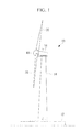
- FIG. 1 is an external view of a wind turbine generator 10 according to this first embodiment.
- the wind turbine generator 10 according to this first embodiment is interconnected with a utility grid for supplying generated power thereto and is installed at sea, for an example.
- the wind turbine generator 10 has a tower (support column) 14 erected upright on a foundation 12, a nacelle 16 installed at the top of the tower 14, and a rotor 18 provided on the nacelle 16 in a manner enabling rotation about a substantially horizontal axis.
- a plurality of (for example, three in this embodiment) blades 20 are attached on the rotor 18 in a radiating pattern about the rotational axis thereof.
- the force of wind striking the blades 20 from direction of the rotational axis of the rotor 18 is converted to a motive force that rotates the rotor 18 about the rotational axis, and this motive force is converted to electrical power by a generator.
- the blades 20 are coupled to the rotor 18 so as to be capable of rotating relative to the wind direction, so that the pitch angle of the blades 20 can be changed.
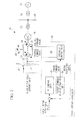
- FIG. 2 is a schematic view showing the electrical configuration in the wind turbine generator 10 according to this first embodiment and the configuration for speeding up the rotation of the rotor 18 using hydraulic pressure and transmitting the rotation to a generator 29 (for example, a synchronous generator).
- the wind turbine generator 10 according to this first embodiment speeds up the rotation of the rotor 18 by means of a hydraulic driving device, which is configured with a cam 30 and a hydraulic pump 32, which are shown in FIG. 3 , and a hydraulic motor 34, and transmits the rotation to the generator 29.
- a rotor shaft 36 is provided on the rotor 18 towards the interior of the nacelle 16, and the circular cam 30, in which a plurality of peaks and valleys are alternately provided in the circumferential direction, is connected to the end of the rotor shaft 36.
- the hydraulic pump 32 which pumps working fluid inside cylinders 40 by means of a plurality of corresponding pistons 38, is provided in the periphery of the cam 30.
- the pistons 38 provided in the hydraulic pump 32 are disposed in a radiating pattern so as to contact the circumferential surface of the cam 30.
- the cam 30 rotates together with the rotation of the rotor 18, whereby the pistons 38 alternately contact the peaks and valleys of the cam 30.
- the pistons 38 expel the working fluid out of the cylinders 40, and when the pistons 38 contact the valleys, the pistons 38 suck the working fluid into the cylinders 40.
- FIG. 3 cross-sections of some of the cylinders 40 and contact states between the pistons 38 and the cam 30 therein are illustrated, and illustrations of the contact states between the pistons 38 and the cam 30 for other cylinders 40 are omitted.
- the hydraulic motor 34 which speeds up the rotation of the rotor 18 and transmits the rotation to the synchronous generator 29, is provided at the end of a shaft 42 of the synchronous generator 29.
- the hydraulic motor 34 is rotated by the working fluid pumped from the hydraulic pump 32 and rotationally drives the synchronous generator 29.
- a plurality of cylinders is disposed in a radiating pattern centered on the shaft 42, and the pistons provided in the cylinders are connected to the shaft 42 via rods.
- the working fluid is pumped into the individual cylinders from the hydraulic pump 32 via a high-pressure manifold 44, whereby the pistons provided in the cylinders undergo reciprocating motion, causing the shaft 42 of the synchronous generator 29 to rotate. Also, the working fluid pushed out from the cylinders of the hydraulic motor 34 is returned to the hydraulic pump 32 via a low-pressure manifold 46.
- the high-pressure manifold 44 is provided with an accumulator 48 that stores the working fluid that flows into and out of the hydraulic pump 32 and the hydraulic motor 34.
- the generator 29 is rotationally driven to generate electric power, is connected to a busbar 50, to which other wind turbine generators 10 etc. are connected, via a boosting transformer 52, and is further connected to a utility grid 58 via an interconnection transformer 56.
- the wind turbine generator 10 is capable of supplying the generated powder output to the utility grid 58.
- the wind turbine generator 10 is provided with a wind turbine controller 60 that controls the wind turbine generator 10.
- the wind turbine controller 60 consists of, for example, a CPU (Central Processing Unit), a RAM (Random Access Memory), a computer readable recording medium, and so forth.
- a processing sequence for implementing individual functions of a PI control unit 62, a torque command value creating unit 64, and a hydraulic control unit 66, described later, is, for example, stored in the recording medium etc. in the form of a program, and by loading this program into the RAM etc. and executing information processing and computation on the CPU, the individual functions are implemented.
- a difference between a target rotor rotational speed indicating a target value for the rotational speed of the rotor 18 and the rotor rotational speed, which is the measured rotational speed of the rotor 18, is input to the PI control unit 62, and a blade-pitch-angle command value is created such that the rotational speed of the rotor 18 is equal to the target rotor rotational speed, and the blade-pitch-angle command value is output to a pitch actuator (not shown) that changes the pitch angles.
- the torque command value creating unit 64 creates a torque command value in accordance with the rotor rotational speed, and outputs it to the hydraulic control unit 66 that controls the hydraulic pump 32 and the hydraulic motor 34.
- table information including the optimal torque command values for the rotor rotational speeds is stored in the torque command value creating unit 64, and the torque command value creating unit 64 creates the torque command value according to the table information.
- the hydraulic control unit 66 outputs the control command value for driving the hydraulic pump 32 and the hydraulic motor 34 to the hydraulic pump 32 and the hydraulic motor 34.
- the hydraulic control unit 66 After receiving the torque command value, the hydraulic control unit 66 according to this first embodiment calculates a driving command value for the pistons configuring the hydraulic pump 32 (hereinafter referred to as "piston-driving command value") on the basis of the result obtained by dividing the allowable maximum torque output of the hydraulic pump 32 by the torque command value.
- the control command value including the piston-driving command value is input to the hydraulic pump 32.
- the hydraulic pump 32 drives the pistons 38 at the positions corresponding to the piston-driving command values, whereby the torque corresponding to the torque command value is output.
- the generator 29 by transmitting this torque to the generator 29 via the hydraulic motor 34 and the shaft 42, the generator 29 generates electric power. Note that the generated power output from the generator 29 is equal to the product of the torque and the rotational speed of the generator 29.
- driving the pistons 38 herein means a state in which all valves (not shown) that control the flow of the working fluid into and out of the cylinders 40 are opened. These valves are provided on the pistons 38(the cylinders 40), respectively, and opening and closing of the individual valves is controlled by the hydraulic control unit 66.
- the valves corresponding to the pistons 38 that are not driven are closed, and the working fluid is not allowed to flow into or out of the cylinders 40.
- the hydraulic control unit 66 when the hydraulic pump 32 is driven with some of the pistons 38 because the wind turbine generator 10 is operated under partial load, the hydraulic control unit 66 according to this first embodiment performs processing that virtually divides the positions at which the pistons 38 are disposed into a plurality of regions (hereinafter referred to as “divided regions") and determines the positions of the pistons 38 to be driven in every divided region such that the pistons 38 to be driven are not disposed at fixed intervals (hereinafter referred to as "driven-piston determining processing").
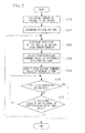
- FIG. 5 is a flow chart showing a flow of processing of a program that is executed by the hydraulic control unit 66 when driven-piston determining processing according to the first embodiment is performed, and the processing is stored in the wind turbine controller 60 in advance.
- the driven-piston determining processing is executed when the wind turbine generator 10 is operated under partial load. In other words, the driven-piston determining processing is not executed when the hydraulic pump 32 is operated under full load of the wind turbine generator 10.
- whether the wind turbine generator 10 is operated under partial load is determined on the basis of, for example, the rotational speed of the rotor 18, the wind speed, and so forth.
- Step 100 the number of pistons 38 to be driven is determined on the basis of the result obtained by dividing the allowable maximum torque output of the hydraulic motor 34 by the torque command value.
- the number of pistons 38 to be driven is calculated by multiplying the result obtained by dividing the maximum torque by the torque command value, by the total number of pistons 38.
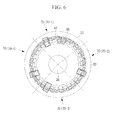
- Step 102 as shown in the example in FIG. 6 , divided regions 70 are determined.
- the numbers of pistons 38 included in respective divided regions 70 are made substantially the same. Therefore, boundaries between the respective divided regions 70 have substantially equal intervals.
- the number of divided regions 70 is made the same as the number of pistons 38 to be driven. As shown in FIG. 6 , for example, if the total number of pistons 38 is thirty four, and if the number of pistons 38 to be driven is four, four divided regions 70 are set (divided regions 70-1 to 70-4). Then, a single piston 38 is driven for each divided region 70. Note that, as shown in an example in FIG. 6 , if the total number of pistons 38 cannot be divided by the number of pistons 38 to be driven without remainder, the remainder is added to a predetermined divided region 70. In other words, in the example shown in FIG.
- the pistons 38 are divided into two divided regions 70 (the divided regions 70-2 and 70-3) including eight pistons 38 and two divided regions 70(the divided regions 70-1 and 70-4) including nine pistons 38.
- the number of pistons 38 to be driven shown in FIG. 6 is merely an example, and the number is not limited to an even number; it may also be an odd number.
- the number of pistons 38 to be driven and the number of divided regions 70 are same, the number of types of variable used for determining the positions of the pistons 38 to be driven is reduced, whereby it is possible to determine the positions of the pistons 38 to be driven more easily.
- the number of divided regions 70 may be different from the number of pistons 38 to be driven, and the number of divided regions 70 may be determined in advance.
- the positions of the pistons 38 to be driven are respectively determined for the divided regions 70 using random numbers.
- random numbers from 1 to 8 or from 1 to 9 are created for the divided regions 70, respectively, and the positions of the pistons 38 to be driven are determined in accordance with the created random numbers.
- the positions of the pistons 38 are preset for the divided regions 70, respectively, in according with the values of the random numbers.
- the positions of the pistons 38 to be driven may be redetermined.
- a piston-driving command value corresponding to partial load is created.
- the piston-driving command value includes the positions of the pistons 38 to be driven.
- Step 108 the piston-driving command value is sent to the hydraulic pump 32.
- Step 110 it is determined whether or not the wind turbine generator 10 is operated under full load or stopped, and in the case of a negative judgment, the process advances to Step 112. On the other hand, in the case of an affirmative judgment, the wind turbine generator 10 is no longer in a state to be operated under partial load, and the process is terminated.
- Step 112 it is determined whether or not the rotational speed of the rotor 18 (the rotor shaft 36) is equal to a redetermining rotational speed at which the positions of the pistons 38 to be driven are predetermined, and in the case of an affirmative judgment, the process returns to Step 104 to redetermine the positions of the pistons 38, and in the case of a negative judgment, the process returns to Step 110.
- the positions of the pistons 38 to be driven are respectively determined for each of the preset rotational speeds of the rotor 18. This processing is done because the determined positions of the pistons 38 to be driven may be biased within the area divided by the divided regions 70.
- the pistons 38 to be driven remain the same pistons 38 over a long period of time, their lifetime is reduced relative to the non-driven pistons 38, and as a result, the maintainability of the wind turbine generator 10 is deteriorated.
- the driven-piston determining processing of this first embodiment even if a bias is caused, because the pistons 38 to be driven are redetermined for every preset rotational speed of the rotor 18, it is possible to eliminate the bias in the positions of the pistons 38 to be driven and to equalize the lifetimes of the pistons 38.
- the positions of the pistons 38 to be driven are preferably determined every revolution of the rotor 18.
- the wind turbine generator 10 is provided with the circular cam 30, in which a plurality of peaks and valleys are alternately provided in the circumferential direction and which is connected to the rotor shaft 36 of the rotor 18 provided with the blades 20, the hydraulic pump 32 that pumps the working fluid by the reciprocating motion of a plurality of the pistons 38, which are disposed in a radiating pattern so as to contact the circumferential surface of the cam 30, caused by the rotation of the rotor shaft 36, and the hydraulic motor 34 that rotates the shaft 42 of the generator 29 by the reciprocating motion of the plurality of pistons caused by the working fluid that has been pumped from the hydraulic pump 32.
- the hydraulic control unit 66 virtually divides the positions at which the pistons 38 are disposed into the plurality of divided regions 70 and determines the positions of the pistons 38 to be driven for the divided regions 70, respectively, such that the pistons 38 to be driven do not have fixed intervals.
- the wind turbine generator 10 can prevent the resonance vibration from being produced even when the hydraulic pump 32 is driven under partial load.
- the configuration of the wind turbine generator 10 according to this second embodiment is similar to that of the wind turbine generator 10 according to the first embodiment shown in FIGs. 1 to 3 , and a description thereof will be omitted.
- FIG. 7 is a flow chart showing a flow of driven-piston determining processing according to this second embodiment. Note that steps in FIG. 7 that are same as the steps in FIG. 5 will be assigned the same reference numerals as those in FIG. 5 , and a description thereof will be omitted partially or completely.
- Step 104' the positions of the pistons 38 to be driven are determined for the divided regions 70, respectively, using mutually orthogonal spreading codes.
- the spreading codes have orthogonality and have low mutual correlation. Therefore, the driven-piston determining processing according to this second embodiment determines the positions of the pistons 38 to be driven using the spreading codes having low mutual correlation, whereby it is possible to prevent the pistons 38 to be driven from having fixed intervals with higher reliability.
- a Gold code is used as the spreading code.
- the positions of the pistons 38 to be driven are determined using the same number of Gold codes as the number of pistons 38 to be driven in the divided regions 70.
- the number of divided regions 70 may be equal to the number of pistons 38 to be driven, which has been determined in Step 100, or may be set as a number of divided regions 70 that is set in advance. If the number of divided regions 70 set in advance is smaller than the number of pistons 38 to be driven, a plurality of pistons 38 to be driven will be positioned in a divided region 70.
- the configuration of the wind turbine generator 10 according to this third embodiment is similar to that of the wind turbine generator 10 according to the first embodiment shown in FIGs. 1 to 3 , and a description thereof will be omitted.
- a flow of the driven-piston determining professing according to this third embodiment is similar to that of the driven-piston determining processing according to the second embodiment.
- an M-sequence code (also referred to as M-sequence signal) expressed by equation (1) is used as the spreading code.
- the number of divided regions 70 may be equal to the number of pistons 38 to be driven, which has been determined in Step 100, or may be set as a number of divided regions 70 that is set in advance. If the number of divided regions 70 set in advance is smaller than the number of pistons 38 to be driven, a plurality of pistons 38 to be driven will be positioned in a divided region 70.
- the driven-piston determining processing is performed on the hydraulic pump 32 when the wind turbine generator 10 is operated under partial load; however, the present invention is not limited thereto, and a form in which the driven-piston determining processing may be performed on the hydraulic motor 34 is also permitted. Alternatively, a form in which the driven-piston determining processing may be performed on both the hydraulic pump 32 and the hydraulic motor 34 is also permitted.
Landscapes
- Engineering & Computer Science (AREA)
- Mechanical Engineering (AREA)
- General Engineering & Computer Science (AREA)
- Life Sciences & Earth Sciences (AREA)
- Sustainable Development (AREA)
- Sustainable Energy (AREA)
- Chemical & Material Sciences (AREA)
- Combustion & Propulsion (AREA)
- Power Engineering (AREA)
- Computer Hardware Design (AREA)
- Wind Motors (AREA)
- Reciprocating Pumps (AREA)
Abstract
A wind turbine generator (10) is provided with a cam, in which a plurality of peaks and valleys are alternately provided in the circumferential direction and which is connected to a rotor shaft (36), a hydraulic pump (32) that pumps working fluid by reciprocating motion of a plurality of pistons, which are disposed in a radiating pattern so as to contact the circumferential surface of cam, caused by rotation of the shaft (36), and a hydraulic motor (34) that rotates a shaft (42) of a generator (29) by reciprocating motion of a plurality of pistons caused by the working fluid. When the hydraulic pump (32) is driven by some of the pistons, a hydraulic control unit (66) virtually divides positions at which the pistons are disposed into a plurality of divided regions and determines positions of the pistons to be driven for each of the divided regions such that the pistons to be driven do not have fixed intervals.
Description
- The present invention relates to a piston controller, a wind turbine generator, and a piston control method.
- In recent years, a wind turbine generator that speeds up the rotation of a rotor provided with blades by means of a hydraulic pump and a hydraulic motor and transmits the rotation to a generator has been developed.
A rotor shaft, going towards the interior of a nacelle, is provided on a rotor, and a circular cam in which a plurality of peaks and valleys are alternately provided in the circumferential direction is connected to the end of the rotor shaft. The hydraulic pump is provided with a plurality of pistons disposed in a radiating pattern so as to contact the circumferential surface of the cam and pumps working fluid by reciprocating motion of the pistons caused by the rotation of the rotor shaft. In other words, when the pistons of the hydraulic pump contact the peaks of the cam, the pistons expel the working fluid out of cylinders, and when the pistons contact the valleys, the pistons suck the working fluid into the cylinders.
Thus, the working fluid is pumped into the individual cylinders configuring the hydraulic motor from the hydraulic pump via a manifold, whereby the pistons provided in the cylinders undergo reciprocating motion. Therefore, a shaft of a generator, which is connected to the pistons, is rotated to perform electric power generation in the generator. - By opening/closing valves that control flow of working fluid flowing into and out of the cylinders, the respective pistons provided in hydraulic pump can be selectively driven or stopped. In the case of full load, all of the pistons are driven. On the other hand, in the case of partial load where the rotational force of the rotor is small, the number of pistons to be driven is reduced.
- In this case, if some of the pistons to be driven are disposed evenly (at fixed intervals), by driving mutually opposing pistons, for example, a resonance vibration having a period equal to the product of the number of pistons being driven and the rotational speed of the rotor is caused. For example, when four pistons are driven, the resonance vibration has a period of four times the rotational speed.
- PTL 1 describes a technique for preventing whirling of a cylinder block for a piston pump/motor, which has a plurality of cylinder bores, within which respective pistons are allowed to slidably move, and which is capable of rotating integrally with a rotating shaft, by providing a weight for rotation balancing of the cylinder block. In other words, with the technique disclosed in PTL 1, the vibration eigenvalue of the cylinder block is changed with the weight, thereby preventing resonance vibration with the natural frequency during whirling of the cylinder block.
- [PTL 1] Japanese Unexamined Patent Application, Publication No.
2006-299822 - However, the technique described in PTL 1, which prevents resonance vibration with the natural frequency by means of the weight, cannot prevent a resonance vibration that is caused by driving pistons disposed at fixed intervals when a hydraulic motor is driven at partial load.
- The present invention has been conceived in light of the above-described circumstances, and an object thereof is to provide a piston controller, a wind turbine generator, and a piston control method that are capable of preventing the occurrence of a resonance vibration even when a hydraulic motor is driven by making working fluid flow in and out by means of some of the pistons.
- In order to solve the problems described above, a piston controller, wind turbine generator, and piston control method of the present invention employ the following solutions.
- A piston controller according to a first aspect of the present invention is a piston controller of a hydraulic driving device including a circular cam, in which a plurality of peaks and valleys are alternately provided in a circumferential direction and which is connected to a shaft and a hydraulic pump that pumps working fluid by a reciprocating motion of a plurality of pistons, which are disposed in a radiating pattern so as to contact the circumferential surface of the cam, caused by rotation of the shaft, wherein when the hydraulic pump is driven by means of some of the pistons, the piston controller virtually divides positions at which the pistons are disposed into a plurality of regions and determines positions of the pistons to be driven for each of the regions such that the pistons to be driven do not have fixed intervals.
- According to this configuration, the rotational force of the shaft is transmitted as a pressure of the working fluid by the circular cam, in which a plurality of peaks and valleys are alternately provided in the circumferential direction and which is connected to the shaft and a hydraulic pump that pumps the working fluid by the reciprocating motion of a plurality of pistons, which are disposed in a radiating pattern so as to contact the circumferential surface of cam, caused by the rotation of the shaft.
- When the hydraulic pump is driven under partial load, the working fluid is made flow in and out by some of the pistons. However, if some of the pistons to be driven are disposed evenly (at fixed intervals), a resonance vibration is produced, for example, by driving mutually opposing pistons.
- Thus, when the hydraulic pump is driven by means of some of the pistons, the positions at which the pistons are disposed are virtually divided into a plurality of regions, and the pistons to be driven are determined for each of the regions such that the pistons to be driven do not have fixed intervals.
By doing so, because no pistons disposed with fixed intervals are driven in this configuration, it is possible to prevent the occurrence of a resonance vibration even when the hydraulic motor is driven by making the working fluid flow in and out by means of some of the pistons. - In the first aspect described above, the number of pistons to be driven and the number of regions may be the same.
- According to this configuration, the number of types of variables used for determining the positions of the pistons to be driven is reduced, whereby it is possible to determine the positions of the pistons to be driven more easily.
- In the first aspect described above, the positions of the pistons to be driven be determined respectively for preset rotational speeds of the shaft.
- According to this configuration, even if the positions of the pistons to be driven are biased, the pistons to be driven are redetermined respectively for the preset rotational speeds of the shaft, whereby it is possible to eliminate the bias in the positions of the pistons to be driven. In addition, the lifetimes of the pistons are also equalized. Note that the positions of the pistons to be driven are preferably determined every revolution of the shaft.
- In the first aspect described above, the positions of the pistons to be driven may be determined for each of the regions using a random number.
- According to this configuration, the positions of the pistons to be driven can easily be determined for each of the regions.
- In the first aspect described above, the positions of the pistons to be driven may be determined for each of the regions using a spreading code.
- Two different spreading codes have orthogonality and have low mutual correlation. The spreading code includes, for example, a Gold code and an M-sequence code (also referred to as an M-sequence signal). Therefore, according to this configuration, the positions of the pistons to be driven are determined using the spreading codes having low mutual correlation, whereby it is possible to more reliably prevent the pistons to be driven from having fixed intervals.
- A wind turbine generator according to a second aspect of the present invention is a wind turbine generator comprising a circular cam, in which a plurality of peaks and valleys are alternately provided in a circumferential direction and which is connected to a shaft of a rotor provided with blades; a hydraulic pump that pumps working fluid by a reciprocating motion of a plurality of pistons, which are disposed in a radiating pattern so as to contact the circumferential surface of the cam, caused by rotation of the shaft of the rotor; a hydraulic motor that rotates a shaft of a generator by a reciprocating motion of a plurality of pistons caused by the working fluid that has been from the hydraulic pump; and the piston controller mentioned above.
- In this configuration, the hydraulic pump and the hydraulic motor speed up the rotation of the rotor and transmit the rotation to the generator. Thus, the wind turbine generator is operated under partial load, the hydraulic pump is driven by means of some of the pistons. In this case, the positions at which the pistons are disposed are virtually divided into a plurality of regions and the pistons to be driven are determined for each of the regions such that the pistons to be driven do not have fixed intervals, whereby this configuration can prevent the occurrence of a resonance vibration even when the hydraulic pump is driven under partial load.
- In the second aspect, when the wind turbine generator is operated under partial load, the piston controller may virtually divide positions at which the piston provided in at least one of the hydraulic pump and the hydraulic motor are disposed into a plurality of regions and may determine positions of the pistons to be driven for each of the regions such that the pistons to be driven do not have fixed intervals.
- In this configuration, even when at least one of the hydraulic pump and the hydraulic motor is driven under partial load, the occurrence of a resonance vibration can be prevented.
- A piston control method according to a third aspect of the present invention is a piston control method of a hydraulic driving device including: a circular cam, in which a plurality of peaks and valleys are alternately provided in a circumferential direction and which is connected to a shaft and a hydraulic pump that pumps working fluid by a reciprocating motion of a plurality of pistons, which are disposed in a radiating pattern so as to contact the circumferential surface of the cam, caused by rotation of the shaft, wherein when the hydraulic pump is driven by means of some of the pistons, the piston control method virtually divides positions at which the piston are disposed into a plurality of regions and determines positions of the pistons to be driven for each of the regions such that the pistons to be driven do not have fixed intervals.
- According to the present invention, an excellent advantage is afforded in that, even when a hydraulic motor is driven by making working fluid flow in and out by means of some of the pistons, the occurrence of a resonance vibration is prevented.
-
- {
Fig. 1} FIG. 1 is an external view of a wind turbine generator according to a first embodiment of the present invention. - {
Fig. 2} FIG. 2 is a schematic view showing an electrical configuration of the wind turbine generator according to the first embodiment of the present invention and a configuration which speeds up the rotation of a rotor using hydraulic pressure and transmits the rotation to a asynchronous generator. - {
Fig. 3} FIG. 3 is a configuration diagram of a hydraulic pump according to the first embodiment of the present invention. - {
Fig. 4} FIG. 4 is a schematic view required for explaining the occurrence of a resonance vibration when a hydraulic pump is driven under partial load in a conventional manner. "Fig. 5} FIG. 5 is a flow chart showing a flow of driven-piston determining processing according to the first embodiment of the present invention. - {
Fig. 6} FIG. 6 is a schematic view showing divided regions in the cylinder according to the first embodiment of the present invention. - {
Fig. 7} FIG. 7 is a flow chart showing a flow of driven-piston determining processing according to the second embodiment of the present invention. - One embodiment of a piston controller, a wind turbine generator, and a piston control method according to the present invention will be described below with reference to the drawings.
- A first embodiment of the present invention will be described below.
-
FIG. 1 is an external view of awind turbine generator 10 according to this first embodiment.
Thewind turbine generator 10 according to this first embodiment is interconnected with a utility grid for supplying generated power thereto and is installed at sea, for an example. Thewind turbine generator 10 has a tower (support column) 14 erected upright on afoundation 12, anacelle 16 installed at the top of thetower 14, and arotor 18 provided on thenacelle 16 in a manner enabling rotation about a substantially horizontal axis. - A plurality of (for example, three in this embodiment)
blades 20 are attached on therotor 18 in a radiating pattern about the rotational axis thereof. Thus, the force of wind striking theblades 20 from direction of the rotational axis of therotor 18 is converted to a motive force that rotates therotor 18 about the rotational axis, and this motive force is converted to electrical power by a generator. Note that theblades 20 are coupled to therotor 18 so as to be capable of rotating relative to the wind direction, so that the pitch angle of theblades 20 can be changed. -
FIG. 2 is a schematic view showing the electrical configuration in thewind turbine generator 10 according to this first embodiment and the configuration for speeding up the rotation of therotor 18 using hydraulic pressure and transmitting the rotation to a generator 29 (for example, a synchronous generator). Thewind turbine generator 10 according to this first embodiment speeds up the rotation of therotor 18 by means of a hydraulic driving device, which is configured with acam 30 and ahydraulic pump 32, which are shown inFIG. 3 , and ahydraulic motor 34, and transmits the rotation to thegenerator 29. - A
rotor shaft 36 is provided on therotor 18 towards the interior of thenacelle 16, and thecircular cam 30, in which a plurality of peaks and valleys are alternately provided in the circumferential direction, is connected to the end of therotor shaft 36.
Thehydraulic pump 32, which pumps working fluid insidecylinders 40 by means of a plurality of correspondingpistons 38, is provided in the periphery of thecam 30.
Thepistons 38 provided in thehydraulic pump 32 are disposed in a radiating pattern so as to contact the circumferential surface of thecam 30. Thus, thecam 30 rotates together with the rotation of therotor 18, whereby thepistons 38 alternately contact the peaks and valleys of thecam 30. When thepistons 38 contact the peaks of thecam 30, thepistons 38 expel the working fluid out of thecylinders 40, and when thepistons 38 contact the valleys, thepistons 38 suck the working fluid into thecylinders 40. - Note that, in
FIG. 3 , cross-sections of some of thecylinders 40 and contact states between thepistons 38 and thecam 30 therein are illustrated, and illustrations of the contact states between thepistons 38 and thecam 30 forother cylinders 40 are omitted. - On the other hand, the
hydraulic motor 34, which speeds up the rotation of therotor 18 and transmits the rotation to thesynchronous generator 29, is provided at the end of ashaft 42 of thesynchronous generator 29. In other words, thehydraulic motor 34 is rotated by the working fluid pumped from thehydraulic pump 32 and rotationally drives thesynchronous generator 29.
In thehydraulic motor 34, a plurality of cylinders is disposed in a radiating pattern centered on theshaft 42, and the pistons provided in the cylinders are connected to theshaft 42 via rods. Thus, in thehydraulic motor 34, the working fluid is pumped into the individual cylinders from thehydraulic pump 32 via a high-pressure manifold 44, whereby the pistons provided in the cylinders undergo reciprocating motion, causing theshaft 42 of thesynchronous generator 29 to rotate. Also, the working fluid pushed out from the cylinders of thehydraulic motor 34 is returned to thehydraulic pump 32 via a low-pressure manifold 46. - The high-
pressure manifold 44 is provided with anaccumulator 48 that stores the working fluid that flows into and out of thehydraulic pump 32 and thehydraulic motor 34. - The
generator 29 is rotationally driven to generate electric power, is connected to abusbar 50, to which otherwind turbine generators 10 etc. are connected, via a boostingtransformer 52, and is further connected to a utility grid 58 via aninterconnection transformer 56. Thus, thewind turbine generator 10 is capable of supplying the generated powder output to the utility grid 58. - In addition, the
wind turbine generator 10 is provided with awind turbine controller 60 that controls thewind turbine generator 10. Thewind turbine controller 60 consists of, for example, a CPU (Central Processing Unit), a RAM (Random Access Memory), a computer readable recording medium, and so forth. A processing sequence for implementing individual functions of aPI control unit 62, a torque commandvalue creating unit 64, and ahydraulic control unit 66, described later, is, for example, stored in the recording medium etc. in the form of a program, and by loading this program into the RAM etc. and executing information processing and computation on the CPU, the individual functions are implemented. - In the
wind turbine controller 60, a difference between a target rotor rotational speed indicating a target value for the rotational speed of therotor 18 and the rotor rotational speed, which is the measured rotational speed of therotor 18, is input to thePI control unit 62, and a blade-pitch-angle command value is created such that the rotational speed of therotor 18 is equal to the target rotor rotational speed, and the blade-pitch-angle command value is output to a pitch actuator (not shown) that changes the pitch angles.
In addition, in thewind turbine controller 60, the torque commandvalue creating unit 64 creates a torque command value in accordance with the rotor rotational speed, and outputs it to thehydraulic control unit 66 that controls thehydraulic pump 32 and thehydraulic motor 34. Note that table information including the optimal torque command values for the rotor rotational speeds is stored in the torque commandvalue creating unit 64, and the torque commandvalue creating unit 64 creates the torque command value according to the table information. - The
hydraulic control unit 66 outputs the control command value for driving thehydraulic pump 32 and thehydraulic motor 34 to thehydraulic pump 32 and thehydraulic motor 34. - After receiving the torque command value, the
hydraulic control unit 66 according to this first embodiment calculates a driving command value for the pistons configuring the hydraulic pump 32 (hereinafter referred to as "piston-driving command value") on the basis of the result obtained by dividing the allowable maximum torque output of thehydraulic pump 32 by the torque command value. The control command value including the piston-driving command value is input to thehydraulic pump 32. Thehydraulic pump 32 drives thepistons 38 at the positions corresponding to the piston-driving command values, whereby the torque corresponding to the torque command value is output. Thus, by transmitting this torque to thegenerator 29 via thehydraulic motor 34 and theshaft 42, thegenerator 29 generates electric power. Note that the generated power output from thegenerator 29 is equal to the product of the torque and the rotational speed of thegenerator 29. - When the
wind turbine generator 10 is operated under full load, all thepistons 38 provided in thehydraulic pump 32 are driven. Note that driving thepistons 38 herein means a state in which all valves (not shown) that control the flow of the working fluid into and out of thecylinders 40 are opened. These valves are provided on the pistons 38(the cylinders 40), respectively, and opening and closing of the individual valves is controlled by thehydraulic control unit 66. On the other hand, in the case in which the rotational force of therotor 18 is low and thewind turbine generator 10 is operated under partial load, only some of thepistons 38 that correspond to partial load are driven. In other words, the valves corresponding to thepistons 38 that are not driven are closed, and the working fluid is not allowed to flow into or out of thecylinders 40. - When the
hydraulic pump 32 is driven under partial load, for example, if, as shown inFIG. 4 , some of thepistons 38 to be driven are disposed evenly (at fixed intervals), by driving the mutually opposingpistons 38, a resonance vibration having a period equal to the product of the number ofpistons 38 being driven and the rotational speed of therotor 18 is caused. In the example shown inFIG. 4 , the number ofpistons 38 being driven (thepistons 38 surrounded by broken lines) is four, and in this case, the period of the resonance vibration becomes four times the rotational speed of therotor 18. - Thus, when the
hydraulic pump 32 is driven with some of thepistons 38 because thewind turbine generator 10 is operated under partial load, thehydraulic control unit 66 according to this first embodiment performs processing that virtually divides the positions at which thepistons 38 are disposed into a plurality of regions (hereinafter referred to as "divided regions") and determines the positions of thepistons 38 to be driven in every divided region such that thepistons 38 to be driven are not disposed at fixed intervals (hereinafter referred to as "driven-piston determining processing"). -
FIG. 5 is a flow chart showing a flow of processing of a program that is executed by thehydraulic control unit 66 when driven-piston determining processing according to the first embodiment is performed, and the processing is stored in thewind turbine controller 60 in advance. Note that the driven-piston determining processing is executed when thewind turbine generator 10 is operated under partial load. In other words, the driven-piston determining processing is not executed when thehydraulic pump 32 is operated under full load of thewind turbine generator 10. Note that whether thewind turbine generator 10 is operated under partial load is determined on the basis of, for example, the rotational speed of therotor 18, the wind speed, and so forth. - First, in
Step 100, the number ofpistons 38 to be driven is determined on the basis of the result obtained by dividing the allowable maximum torque output of thehydraulic motor 34 by the torque command value. The number ofpistons 38 to be driven is calculated by multiplying the result obtained by dividing the maximum torque by the torque command value, by the total number ofpistons 38. - In the
next Step 102, as shown in the example inFIG. 6 , dividedregions 70 are determined.
The numbers ofpistons 38 included in respective dividedregions 70 are made substantially the same. Therefore, boundaries between the respective dividedregions 70 have substantially equal intervals. - In addition, in this first embodiment, the number of divided
regions 70 is made the same as the number ofpistons 38 to be driven. As shown inFIG. 6 , for example, if the total number ofpistons 38 is thirty four, and if the number ofpistons 38 to be driven is four, four dividedregions 70 are set (divided regions 70-1 to 70-4). Then, asingle piston 38 is driven for each dividedregion 70.
Note that, as shown in an example inFIG. 6 , if the total number ofpistons 38 cannot be divided by the number ofpistons 38 to be driven without remainder, the remainder is added to a predetermined dividedregion 70. In other words, in the example shown inFIG. 6 , thepistons 38 are divided into two divided regions 70 (the divided regions 70-2 and 70-3) including eightpistons 38 and two divided regions 70(the divided regions 70-1 and 70-4) including ninepistons 38.
Note that, the number ofpistons 38 to be driven shown inFIG. 6 is merely an example, and the number is not limited to an even number; it may also be an odd number. - As described above, by virtually dividing the positions at which the
pistons 38 are disposed into the plurality of dividedregions 70 and respectively setting the positions of thepistons 38 to be driven for each of the dividedregions 70, it is possible to prevent the positions of thepistons 38 to be driven from being biased in one direction. - By making the number of
pistons 38 to be driven and the number of dividedregions 70 the same, the number of types of variable used for determining the positions of thepistons 38 to be driven is reduced, whereby it is possible to determine the positions of thepistons 38 to be driven more easily. Note that the number of dividedregions 70 may be different from the number ofpistons 38 to be driven, and the number of dividedregions 70 may be determined in advance. - In the
next Step 104, the positions of thepistons 38 to be driven are respectively determined for the dividedregions 70 using random numbers. In the example shown inFIG. 6 , random numbers from 1 to 8 or from 1 to 9 are created for the dividedregions 70, respectively, and the positions of thepistons 38 to be driven are determined in accordance with the created random numbers. Note that the positions of thepistons 38 are preset for the dividedregions 70, respectively, in according with the values of the random numbers.
In addition, if the determined positions of thepistons 38 have fixed intervals, the positions of thepistons 38 to be driven may be redetermined. - In the
next Step 106, a piston-driving command value corresponding to partial load is created. The piston-driving command value includes the positions of thepistons 38 to be driven. - In the
next Step 108, the piston-driving command value is sent to thehydraulic pump 32. - In the
next Step 110, it is determined whether or not thewind turbine generator 10 is operated under full load or stopped, and in the case of a negative judgment, the process advances to Step 112. On the other hand, in the case of an affirmative judgment, thewind turbine generator 10 is no longer in a state to be operated under partial load, and the process is terminated. - In
Step 112, it is determined whether or not the rotational speed of the rotor 18 (the rotor shaft 36) is equal to a redetermining rotational speed at which the positions of thepistons 38 to be driven are predetermined, and in the case of an affirmative judgment, the process returns to Step 104 to redetermine the positions of thepistons 38, and in the case of a negative judgment, the process returns to Step 110. - As described above, in the driven-piston determining processing, the positions of the
pistons 38 to be driven are respectively determined for each of the preset rotational speeds of therotor 18. This processing is done because the determined positions of thepistons 38 to be driven may be biased within the area divided by the dividedregions 70. In addition, if thepistons 38 to be driven remain thesame pistons 38 over a long period of time, their lifetime is reduced relative to thenon-driven pistons 38, and as a result, the maintainability of thewind turbine generator 10 is deteriorated. According to the driven-piston determining processing of this first embodiment, even if a bias is caused, because thepistons 38 to be driven are redetermined for every preset rotational speed of therotor 18, it is possible to eliminate the bias in the positions of thepistons 38 to be driven and to equalize the lifetimes of thepistons 38. Note that the positions of thepistons 38 to be driven are preferably determined every revolution of therotor 18. - As explained above, the
wind turbine generator 10 according to this first embodiment is provided with thecircular cam 30, in which a plurality of peaks and valleys are alternately provided in the circumferential direction and which is connected to therotor shaft 36 of therotor 18 provided with theblades 20, thehydraulic pump 32 that pumps the working fluid by the reciprocating motion of a plurality of thepistons 38, which are disposed in a radiating pattern so as to contact the circumferential surface of thecam 30, caused by the rotation of therotor shaft 36, and thehydraulic motor 34 that rotates theshaft 42 of thegenerator 29 by the reciprocating motion of the plurality of pistons caused by the working fluid that has been pumped from thehydraulic pump 32. Whenhydraulic pump 32 is driven by some of thepistons 38 because thewind turbine generator 10 is operated under partial load, thehydraulic control unit 66 virtually divides the positions at which thepistons 38 are disposed into the plurality of dividedregions 70 and determines the positions of thepistons 38 to be driven for the dividedregions 70, respectively, such that thepistons 38 to be driven do not have fixed intervals. - Therefore, the
wind turbine generator 10 according to this first embodiment can prevent the resonance vibration from being produced even when thehydraulic pump 32 is driven under partial load. - A second embodiment of the present invention will be described below.
- Note that the configuration of the
wind turbine generator 10 according to this second embodiment is similar to that of thewind turbine generator 10 according to the first embodiment shown inFIGs. 1 to 3 , and a description thereof will be omitted. -
FIG. 7 is a flow chart showing a flow of driven-piston determining processing according to this second embodiment. Note that steps inFIG. 7 that are same as the steps inFIG. 5 will be assigned the same reference numerals as those inFIG. 5 , and a description thereof will be omitted partially or completely. - In Step 104' according to this second embodiment, the positions of the
pistons 38 to be driven are determined for the dividedregions 70, respectively, using mutually orthogonal spreading codes. The spreading codes have orthogonality and have low mutual correlation. Therefore, the driven-piston determining processing according to this second embodiment determines the positions of thepistons 38 to be driven using the spreading codes having low mutual correlation, whereby it is possible to prevent thepistons 38 to be driven from having fixed intervals with higher reliability. - Note that, in this second embodiment, a Gold code is used as the spreading code.
In Step 104', for example, the positions of thepistons 38 to be driven are determined using the same number of Gold codes as the number ofpistons 38 to be driven in the dividedregions 70.
Note that the number of dividedregions 70 may be equal to the number ofpistons 38 to be driven, which has been determined inStep 100, or may be set as a number of dividedregions 70 that is set in advance. If the number of dividedregions 70 set in advance is smaller than the number ofpistons 38 to be driven, a plurality ofpistons 38 to be driven will be positioned in a dividedregion 70. - A third embodiment of the present invention will be described below.
- Note that the configuration of the
wind turbine generator 10 according to this third embodiment is similar to that of thewind turbine generator 10 according to the first embodiment shown inFIGs. 1 to 3 , and a description thereof will be omitted. - A flow of the driven-piston determining professing according to this third embodiment is similar to that of the driven-piston determining processing according to the second embodiment. However, in Step 104' according to this third embodiment, an M-sequence code (also referred to as M-sequence signal) expressed by equation (1) is used as the spreading code.

- In Step 104', for example, an M-sequence code in which n = 1 is used in a first divided
region 70, an M-sequence code in which n = 2 is used in a second dividedregion 70, and an M-sequence code in which n = N is used in an Nth dividedregion 70, thereby determining the positions of thepistons 38 to be driven.
Note that the number of dividedregions 70 may be equal to the number ofpistons 38 to be driven, which has been determined inStep 100, or may be set as a number of dividedregions 70 that is set in advance. If the number of dividedregions 70 set in advance is smaller than the number ofpistons 38 to be driven, a plurality ofpistons 38 to be driven will be positioned in a dividedregion 70. - Although the present invention has been described above using the individual embodiments described above, the technical scope of the present invention is not limited to the scope stated in the embodiments described above. carious modifications and improvements can be made to the individual embodiments described above, so long as they do not depart from the spirit of the invention, and other forms in which such modifications or improvements are made are also encompassed by the technical scope of the present invention.
- For example, in the individual embodiments described above, a description has been given of a form in which the driven-piston determining processing is performed on the
hydraulic pump 32 when thewind turbine generator 10 is operated under partial load; however, the present invention is not limited thereto, and a form in which the driven-piston determining processing may be performed on thehydraulic motor 34 is also permitted. Alternatively, a form in which the driven-piston determining processing may be performed on both thehydraulic pump 32 and thehydraulic motor 34 is also permitted. - In addition, in the second and third embodiments described above, a description has been given of a form in which a Gold code and an M-sequence code are used as the spreading code; however, the present invention is not limited thereto, and a code other than a Gold code and an M-sequence code may be used as the spreading code.
- In addition, the flow of the driven-piston determining processing described in the above-mentioned individual embodiments is also merely an example; unnecessary steps may be removed, new steps may be added, and the order of the processes may be changed, so long as they do not depart from the spirit of the present invention.
-
- 10
- wind turbine generator
- 18
- rotor
- 20
- blade
- 29
- generator
- 30
- cam
- 32
- hydraulic pump
- 34
- hydraulic motor
- 36
- rotor shaft
- 38
- piston
- 66
- hydraulic control unit
- 70
- divided regions
Claims (8)
- A piston controller of a hydraulic driving device including a circular cam (30), in which a plurality of peaks and valleys are alternately provided in a circumferential direction and which is connected to a shaft (36) and a hydraulic pump (32) that pumps working fluid by a reciprocating motion of a plurality of pistons (38), which are disposed in a radiating pattern so as to contact the circumferential surface of the cam (30), caused by rotation of the shaft (36),
wherein, when the hydraulic pump (32) is driven by means of some of the pistons (38), the piston controller virtually divides positions at which the pistons (38) are disposed into a plurality of regions (70) and determines positions of the pistons (38) to be driven for each of the regions (70) such that the pistons (38) to be driven do not have fixed intervals. - The piston controller according to Claim 1, wherein the number of pistons (38) to be driven and the number of regions (70) are the same.
- The piston controller according to Claim 1 or 2, wherein positions of the pistons (38) to be driven are determined for every preset rotational speed of the shaft (36).
- The piston controller according to any one of Claims 1 to 3, wherein positions of the pistons (38) to be driven are determined for each of the regions using a random number.
- The piston controller according to any one of Claims 1 to 3, wherein positions of the pistons (38) to be driven are determined for each of the regions using a spreading code.
- A wind turbine generator comprising:a circular cam (30), in which a plurality of peaks and valleys are alternately provided in a circumferential direction and which is connected to a shaft (36) of a motor provided with blades (20);a hydraulic pump (32) that pumps working fluid by a reciprocating motion of a plurality of pistons (38), which are disposed in a radiating pattern so as to contact the circumferential surface of the cam (30), caused by rotation of the shaft (36) of the rotor;a hydraulic motor (34) that rotates a shaft (42) of a generator (29) by a reciprocating motion of a plurality of pistons caused by the working fluid that has been pumped from the hydraulic pump (32); andthe piston controller according to any one of Claims 1 to 5.
- The wind turbine generator according to Claim 6, wherein when the wind turbine generator is operated under partial load, the piston controller virtually divides positions at which the pistons provided in at least one of the hydraulic pump (32) and the hydraulic motor (34) are disposed into a plurality of regions and determines positions of the pistons to be driven for each of the regions such that the pistons to be driven do not have fixed intervals.
- A piston control method of a hydraulic driving device including: a circular cam (30), in which a plurality of peaks and valleys are alternately provided in a circumferential direction and which is connected to a shaft (36) and a hydraulic pump (32) that pumps working fluid by a reciprocating motion of a plurality of pistons (38), which are disposed in a radiating pattern so as to contact the circumferential surface of the cam (30), caused by rotation of the shaft (36),
wherein when the hydraulic pump (32) is driven by means of some of the pistons (38), the piston control method virtually divides positions at which the pistons (38) are disposed into a plurality of regions (70) and determines positions of the pistons (38) to be driven for each of the regions (70) such that the pitons (38) to be driven do not have fixed intervals.
Applications Claiming Priority (1)
| Application Number | Priority Date | Filing Date | Title |
|---|---|---|---|
| JP2012018007A JP5693480B2 (en) | 2012-01-31 | 2012-01-31 | Piston control device, wind power generator, and piston control method |
Publications (1)
| Publication Number | Publication Date |
|---|---|
| EP2623779A2 true EP2623779A2 (en) | 2013-08-07 |
Family
ID=47739028
Family Applications (1)
| Application Number | Title | Priority Date | Filing Date |
|---|---|---|---|
| EP13152893.7A Withdrawn EP2623779A2 (en) | 2012-01-31 | 2013-01-28 | Piston controller, wind turbine generator, and piston control method |
Country Status (2)
| Country | Link |
|---|---|
| EP (1) | EP2623779A2 (en) |
| JP (1) | JP5693480B2 (en) |
Cited By (3)
| Publication number | Priority date | Publication date | Assignee | Title |
|---|---|---|---|---|
| EP2851562A1 (en) * | 2013-09-18 | 2015-03-25 | Mitsubishi Heavy Industries, Ltd. | Hydraulic transmission |
| US9976641B2 (en) | 2013-09-18 | 2018-05-22 | Artemis Intelligent Power Limited | Hydraulic transmission |
| CN111512043A (en) * | 2017-11-06 | 2020-08-07 | 维斯塔斯风力系统集团公司 | Method and system for controlling wind turbines to manage edge blade vibration |
Families Citing this family (1)
| Publication number | Priority date | Publication date | Assignee | Title |
|---|---|---|---|---|
| JP5936585B2 (en) * | 2013-09-02 | 2016-06-22 | 三菱重工業株式会社 | DRIVE DEVICE CONTROL DEVICE, WIND POWER GENERATOR, AND DRIVE DEVICE CONTROL METHOD |
Family Cites Families (2)
| Publication number | Priority date | Publication date | Assignee | Title |
|---|---|---|---|---|
| DE4127751C1 (en) * | 1991-08-22 | 1992-11-12 | Mercedes-Benz Aktiengesellschaft, 7000 Stuttgart, De | |
| GB2477997B (en) * | 2010-02-23 | 2015-01-14 | Artemis Intelligent Power Ltd | Fluid working machine and method for operating fluid working machine |
-
2012
- 2012-01-31 JP JP2012018007A patent/JP5693480B2/en not_active Expired - Fee Related
-
2013
- 2013-01-28 EP EP13152893.7A patent/EP2623779A2/en not_active Withdrawn
Cited By (5)
| Publication number | Priority date | Publication date | Assignee | Title |
|---|---|---|---|---|
| EP2851562A1 (en) * | 2013-09-18 | 2015-03-25 | Mitsubishi Heavy Industries, Ltd. | Hydraulic transmission |
| US9976641B2 (en) | 2013-09-18 | 2018-05-22 | Artemis Intelligent Power Limited | Hydraulic transmission |
| CN111512043A (en) * | 2017-11-06 | 2020-08-07 | 维斯塔斯风力系统集团公司 | Method and system for controlling wind turbines to manage edge blade vibration |
| CN111512043B (en) * | 2017-11-06 | 2022-04-29 | 维斯塔斯风力系统集团公司 | Method and system for controlling wind turbines to manage edge blade vibration |
| US11384731B2 (en) | 2017-11-06 | 2022-07-12 | Vestas Wind Systems A/S | Method and system for controlling a wind turbine to manage edgewise blade vibrations |
Also Published As
| Publication number | Publication date |
|---|---|
| JP5693480B2 (en) | 2015-04-01 |
| JP2013155694A (en) | 2013-08-15 |
Similar Documents
| Publication | Publication Date | Title |
|---|---|---|
| EP2963283B1 (en) | Methods and systems to operate a wind turbine system | |
| Penalba et al. | A review of wave-to-wire models for wave energy converters | |
| US10100812B2 (en) | Methods and systems to operate a wind turbine system | |
| WO2011011682A2 (en) | Wind turbine drive system | |
| EP2851562B1 (en) | Hydraulic transmission | |
| JP5788079B2 (en) | Method for synchronizing generator drive with AC power network | |
| JP5693480B2 (en) | Piston control device, wind power generator, and piston control method | |
| Gonzalez-Delgado et al. | Design and optimization of multi-MW offshore direct-drive wind turbine electrical generator structures using generative design techniques | |
| Joshi et al. | Selecting a high specific speed pump for low head hydro-electric power generation | |
| EP2615277A2 (en) | Turbomachine drive arrangement | |
| Schulte | Control-oriented description of large scale wind turbines with hydrostatic transmission using Takagi-Sugeno models | |
| Pedersen et al. | Lqr feedback control development for wind turbines featuring a digital fluid power transmission system | |
| EP2889710B1 (en) | Diagnostic method and diagnostic device for hydraulic machine | |
| Schulte et al. | Nonlinear control of wind turbines with hydrostatic transmission based on takagi-sugeno model | |
| EP2889514A1 (en) | Hydraulic transmission, power generating apparatus of renewable energy type and operation method thereof | |
| Laguna | Steady-state performance of the delft offshore turbine | |
| Katgeri et al. | A review & progress on digital hydraulic pumps and valves | |
| EP3098450A1 (en) | Method and apparatus for diagnosing a hydraulic machine, power generating apparatus of renewable-energy type, and method of diagnosing the same | |
| Plagge et al. | Next-generation hydrokinetic power take-off via a novel variable-stroke hydraulic system | |
| KR101656674B1 (en) | Power generating apparatus having hydraulic machineries | |
| EP2889516B1 (en) | A hydraulic transmission and a power generating apparatus of a renewable energy type | |
| Mostafa | Direct drive wind turbines: the effect of unbalanced magnetic pull on permanent magnet generators and bearing arrangements | |
| Pimenta et al. | Calibration of onshore wind turbine numerical model using experimental data | |
| He¹ et al. | Performance study of energy | |
| EP2899432B1 (en) | Hydraulic transmission, power generating apparatus of renewable energy type, and operation method thereof |
Legal Events
| Date | Code | Title | Description |
|---|---|---|---|
| PUAI | Public reference made under article 153(3) epc to a published international application that has entered the european phase |
Free format text: ORIGINAL CODE: 0009012 |
|
| AK | Designated contracting states |
Kind code of ref document: A2 Designated state(s): AL AT BE BG CH CY CZ DE DK EE ES FI FR GB GR HR HU IE IS IT LI LT LU LV MC MK MT NL NO PL PT RO RS SE SI SK SM TR |
|
| AX | Request for extension of the european patent |
Extension state: BA ME |
|
| STAA | Information on the status of an ep patent application or granted ep patent |
Free format text: STATUS: THE APPLICATION HAS BEEN WITHDRAWN |
|
| 18W | Application withdrawn |
Effective date: 20141001 |