EP2623725A2 - Fan case assembly - Google Patents
Fan case assembly Download PDFInfo
- Publication number
- EP2623725A2 EP2623725A2 EP13152540.4A EP13152540A EP2623725A2 EP 2623725 A2 EP2623725 A2 EP 2623725A2 EP 13152540 A EP13152540 A EP 13152540A EP 2623725 A2 EP2623725 A2 EP 2623725A2
- Authority
- EP
- European Patent Office
- Prior art keywords
- fan
- assembly
- fan case
- case
- liner
- Prior art date
- Legal status (The legal status is an assumption and is not a legal conclusion. Google has not performed a legal analysis and makes no representation as to the accuracy of the status listed.)
- Granted
Links
Images


Classifications
-
- F—MECHANICAL ENGINEERING; LIGHTING; HEATING; WEAPONS; BLASTING
- F01—MACHINES OR ENGINES IN GENERAL; ENGINE PLANTS IN GENERAL; STEAM ENGINES
- F01D—NON-POSITIVE DISPLACEMENT MACHINES OR ENGINES, e.g. STEAM TURBINES
- F01D11/00—Preventing or minimising internal leakage of working-fluid, e.g. between stages
- F01D11/08—Preventing or minimising internal leakage of working-fluid, e.g. between stages for sealing space between rotor blade tips and stator
- F01D11/14—Adjusting or regulating tip-clearance, i.e. distance between rotor-blade tips and stator casing
- F01D11/16—Adjusting or regulating tip-clearance, i.e. distance between rotor-blade tips and stator casing by self-adjusting means
-
- F—MECHANICAL ENGINEERING; LIGHTING; HEATING; WEAPONS; BLASTING
- F01—MACHINES OR ENGINES IN GENERAL; ENGINE PLANTS IN GENERAL; STEAM ENGINES
- F01D—NON-POSITIVE DISPLACEMENT MACHINES OR ENGINES, e.g. STEAM TURBINES
- F01D11/00—Preventing or minimising internal leakage of working-fluid, e.g. between stages
- F01D11/08—Preventing or minimising internal leakage of working-fluid, e.g. between stages for sealing space between rotor blade tips and stator
- F01D11/12—Preventing or minimising internal leakage of working-fluid, e.g. between stages for sealing space between rotor blade tips and stator using a rubstrip, e.g. erodible. deformable or resiliently-biased part
- F01D11/122—Preventing or minimising internal leakage of working-fluid, e.g. between stages for sealing space between rotor blade tips and stator using a rubstrip, e.g. erodible. deformable or resiliently-biased part with erodable or abradable material
-
- F—MECHANICAL ENGINEERING; LIGHTING; HEATING; WEAPONS; BLASTING
- F01—MACHINES OR ENGINES IN GENERAL; ENGINE PLANTS IN GENERAL; STEAM ENGINES
- F01D—NON-POSITIVE DISPLACEMENT MACHINES OR ENGINES, e.g. STEAM TURBINES
- F01D11/00—Preventing or minimising internal leakage of working-fluid, e.g. between stages
- F01D11/08—Preventing or minimising internal leakage of working-fluid, e.g. between stages for sealing space between rotor blade tips and stator
- F01D11/12—Preventing or minimising internal leakage of working-fluid, e.g. between stages for sealing space between rotor blade tips and stator using a rubstrip, e.g. erodible. deformable or resiliently-biased part
- F01D11/127—Preventing or minimising internal leakage of working-fluid, e.g. between stages for sealing space between rotor blade tips and stator using a rubstrip, e.g. erodible. deformable or resiliently-biased part with a deformable or crushable structure, e.g. honeycomb
-
- F—MECHANICAL ENGINEERING; LIGHTING; HEATING; WEAPONS; BLASTING
- F01—MACHINES OR ENGINES IN GENERAL; ENGINE PLANTS IN GENERAL; STEAM ENGINES
- F01D—NON-POSITIVE DISPLACEMENT MACHINES OR ENGINES, e.g. STEAM TURBINES
- F01D21/00—Shutting-down of machines or engines, e.g. in emergency; Regulating, controlling, or safety means not otherwise provided for
- F01D21/04—Shutting-down of machines or engines, e.g. in emergency; Regulating, controlling, or safety means not otherwise provided for responsive to undesired position of rotor relative to stator or to breaking-off of a part of the rotor, e.g. indicating such position
- F01D21/045—Shutting-down of machines or engines, e.g. in emergency; Regulating, controlling, or safety means not otherwise provided for responsive to undesired position of rotor relative to stator or to breaking-off of a part of the rotor, e.g. indicating such position special arrangements in stators or in rotors dealing with breaking-off of part of rotor
-
- F—MECHANICAL ENGINEERING; LIGHTING; HEATING; WEAPONS; BLASTING
- F02—COMBUSTION ENGINES; HOT-GAS OR COMBUSTION-PRODUCT ENGINE PLANTS
- F02K—JET-PROPULSION PLANTS
- F02K3/00—Plants including a gas turbine driving a compressor or a ducted fan
- F02K3/02—Plants including a gas turbine driving a compressor or a ducted fan in which part of the working fluid by-passes the turbine and combustion chamber
- F02K3/04—Plants including a gas turbine driving a compressor or a ducted fan in which part of the working fluid by-passes the turbine and combustion chamber the plant including ducted fans, i.e. fans with high volume, low pressure outputs, for augmenting the jet thrust, e.g. of double-flow type
- F02K3/06—Plants including a gas turbine driving a compressor or a ducted fan in which part of the working fluid by-passes the turbine and combustion chamber the plant including ducted fans, i.e. fans with high volume, low pressure outputs, for augmenting the jet thrust, e.g. of double-flow type with front fan
-
- F—MECHANICAL ENGINEERING; LIGHTING; HEATING; WEAPONS; BLASTING
- F05—INDEXING SCHEMES RELATING TO ENGINES OR PUMPS IN VARIOUS SUBCLASSES OF CLASSES F01-F04
- F05D—INDEXING SCHEME FOR ASPECTS RELATING TO NON-POSITIVE-DISPLACEMENT MACHINES OR ENGINES, GAS-TURBINES OR JET-PROPULSION PLANTS
- F05D2250/00—Geometry
- F05D2250/70—Shape
- F05D2250/75—Shape given by its similarity to a letter, e.g. T-shaped
-
- Y—GENERAL TAGGING OF NEW TECHNOLOGICAL DEVELOPMENTS; GENERAL TAGGING OF CROSS-SECTIONAL TECHNOLOGIES SPANNING OVER SEVERAL SECTIONS OF THE IPC; TECHNICAL SUBJECTS COVERED BY FORMER USPC CROSS-REFERENCE ART COLLECTIONS [XRACs] AND DIGESTS
- Y02—TECHNOLOGIES OR APPLICATIONS FOR MITIGATION OR ADAPTATION AGAINST CLIMATE CHANGE
- Y02T—CLIMATE CHANGE MITIGATION TECHNOLOGIES RELATED TO TRANSPORTATION
- Y02T50/00—Aeronautics or air transport
- Y02T50/60—Efficient propulsion technologies, e.g. for aircraft
Definitions
- the disclosure relates to gas turbine engines. More particularly, the disclosure relates to fan tip clearance accommodation.
- turbofan engines differences in the fan material versus fan case material may contribute to thermally-induced rub.
- Turbine engine fans and their cases experience differential thermal expansion across an operational range. For example, on the ground they are subject to a normal range in atmospheric temperatures (e.g., from 20C to 40C with an exemplary ambient temperature being 21C). In flight, however, temperatures will typically decrease. Whereas other portions of the engine are subject to heating, the fan, and moreso, fan case temperatures may decrease at altitude (e.g., to an exemplary -60C to -45C). An exemplary temperature decrease from ground to altitude may be in excess of 50C, more narrowly, 60-80C or an exemplary 70C.
- the decrease in temperature will cause the fan to decrease in diameter more than the fan case (due to the fan having a higher coefficient of thermal expansion (CTE) than a structural portion of the fan case).
- CTE coefficient of thermal expansion
- a turbine engine fan case assembly This includes a structural case and a liner assembly.
- a radially accommodating attachment system connects the liner assembly to the structural case.
- the attachment system comprises a circumferentially-distributed plurality of longitudinally elongate radially outwardly open channels mounted to the liner assembly.
- the attachment system further comprises an associated plurality of inwardly-projecting tongues mounted to the structural case. Each tongue is accommodated in an associated said channel.
- the tongues are of tongue members each comprising a T sectioned rail, the arms of the T forming a flange mounted to the structural case, and the leg of the T forming the tongue, and the channels are formed by a member having, in cross section, a channel base, a pair of sidewalls extending radially outward from opposite sides of the base and a pair of mounting flanges extending circumferentially outward from radially outboard edges of the sidewalls.
- each T-sectioned rail is a non metallic rail and the member is a non metallic member.
- the non-metallic rail comprises injection molded thermoplastic and the non-metallic member comprises injection molded thermoplastic.
- the channels extend within a honeycomb material. In additional or alternative embodiments of any of the foregoing embodiments, there are 4-10 of said channels and tongues. In additional or alternative embodiments of any of the foregoing embodiments, the channels have a fore to aft depth increase. In additional or alternative embodiments of any of the foregoing embodiments, the tongues are a molded or extruded plastic and the channels are a molded or extruded plastic.
- the structural case comprises a non-metallic member principally dictating thermal expansion of the structural case and the liner assembly comprises a metallic member principally dictating thermal expansion of the liner assembly.
- the non-metallic member may comprise a carbon fiber member.
- a turbine engine may comprise a fan case assembly of any of the foregoing embodiments and a fan encircled by the fan case.
- the structural case comprises a non metallic member principally dictating thermal expansion of the structural case
- the liner assembly comprises a metallic member principally dictating thermal expansion of the liner assembly and the liner assembly metallic member has a coefficient of thermal expansion within 5% of a coefficient of thermal expansion of blades of the fan.
- a longitudinally elongate radially outwardly open channel for mounting to a liner assembly and an associated inwardly projecting tongue for mounting to the structural case, and dimensioned to be accommodated in said channel.
- a longitudinally elongate radially outwardly open channel is provided for mounting to a liner assembly.
- An associated inwardly projecting tongue is provided for mounting a structural case and is dimensioned to be accommodated in said channel.
- the inwardly projecting tongue is formed by the leg of a T-sectioned member.
- the outwardly open channel is formed having a U-shaped cross-section further comprising a pair of circumferentially outwardly extending segments.
- FIG. 1 shows a turbofan engine 20 having a centerline or central longitudinal axis 500.
- the engine includes a fan 22 at a forward/upstream end of the engine.
- the fan 22 has a circumferential array of fan blades 24.
- the exemplary blades 24 each have an airfoil 26 extending from a proximal end 28 to a distal end or tip 30.
- Each blade airfoil extends from a leading edge 32 to a trailing edge 34 and has pressure side 36 and a suction side 38.
- each blade may include an attachment root 40 mounted in a complementary feature (e.g., a slot) 42 of a fan hub 44.
- the blade tips 30 are in close facing proximity to the inner/inboard surface 46 of a fan case 48.
- the exemplary fan case 48 is within an aerodynamic fan nacelle 50.
- the nacelle 50 extends from an upstream end/rim 52 to a downstream end/rim 54.
- Downstream of the fan along a core flowpath 60 are, sequentially, one or more compressor sections 62, 64, a combustor section 66, and one or more turbine sections 68, 70.
- the low pressure compressor section 62 is coupled to the low pressure turbine section 70 via a shaft 72.
- the high pressure compressor section 64 is coupled to the high pressure turbine section 68 via a shaft 74.
- the compressor sections sequentially compress a core flow of air received from the fan and deliver the compressed air to the combustor where the compressed air is mixed with fuel and combusted to generate high pressure combustion gases. These gases are sequentially expanded in the turbine sections to, in turn, drive the compressor sections.
- Each of the compressor sections and turbine sections may include one or more stages of blades interspersed with stages of vanes.
- the fan may be driven directly or indirectly by one of the turbine sections.
- the fan may be coupled to the shaft 72 by a transmission so that the fan rotates about the centerline at a slower speed than does the shaft 72.
- the core flowpath passes through an engine case 80.
- the engine case may be within an aerodynamic nacelle 82.
- Bearing systems may support the shafts and fan relative to the engine case for rotation about the centerline 500.
- a circumferential array of struts 84 may position the fan case relative to the engine case.
- the exemplary struts 84 are aft/downstream of the fan and extend across a bypass flowpath 86 outboard of the core flowpath.
- a pylon 90 may have a proximal end (not shown) mounted to the aircraft fuselage or wing. A distal end of the pylon may mount to the engine.
- the exemplary mounting involves connection to both the fan case and the engine case.
- the fan blades are subject to radial expansion due to inertial forces associated with fan rotation (centrifugal loading).
- the fan blades are also subject to thermal expansion which is influenced by the material properties of the fan blades (e.g., the coefficient of thermal expansion (CTE)).
- CTE coefficient of thermal expansion
- the fan case is also subject to thermal expansion. In operation, there typically is a gap or clearance between the fan blade tips and the adjacent inboard surface portion of the fan case. On the one hand, it is desirable to keep this gap small to maintain engine efficiency. On the other hand, it is generally desirable to avoid having this gap fully close which produces rub.
- a radial accomodation of the liner may minimize variation of the fan blade tip clearance during engine operation.
- the accomodation matches the thermal expansion of the liner to the blade material, independent of the thermal expansion of the containment case, thereby allowing an optimal selection of material properties of both the fan and case to minimize weight and maximize performance.
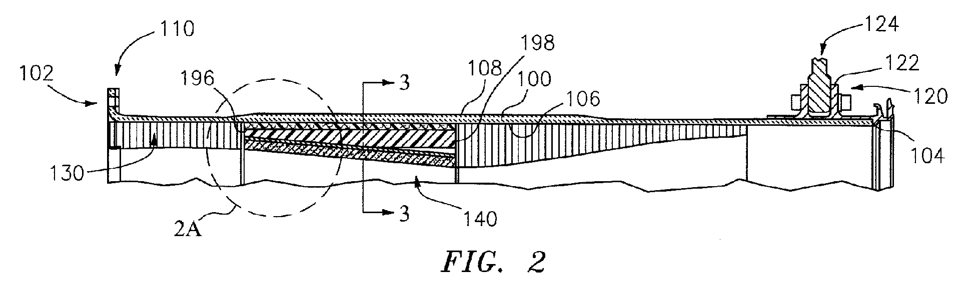
- FIG. 2 shows further details of the fan case.
- the fan case includes a structural member/case comprising a containment case 100.
- the exemplary containment case is formed as a composite (e.g., carbon fiber and epoxy resin).
- the exemplary containment case is a full circumference/hoop structure.
- the exemplary containment case extends from an upstream rim/end 102 to a downstream rim/end 104.
- the containment case 100 has an inner/inboard surface 106 and an outer/outboard surface 108. Proximate the upstream end 102, the containment case has a radially outwardly projecting flange 110.
- the fan case further includes a mounting ring structure 120 mounted to and encircling a downstream end portion of the containment case.
- the mounting ring structure may be formed of metal (e.g., titanium or aluminum) and may have a clevis or other mounting structure 122 for mounting to a forward engine amount of the pylon (e.g. via a mounting lug 124).
- structures are mounted to the inboard surface 106 to define locally the outboard boundary of the core flowpath.
- a forward acoustic liner 130 Proximate the upstream end 102, is a forward acoustic liner 130.
- This may be formed of a honeycomb (e.g., a potted honeycomb 132 (e.g., aluminum alloy) having a liner 134 (e.g., fiberglass) ( FIG. 2A ).
- the liner and honeycomb may be bonded via adhesive (e.g., an epoxy also bonding the honeycomb to the surface 106).
- the liner assembly 140 Downstream/aft of the forward acoustic liner 130 is an abradable liner assembly 140.
- the liner assembly 140 includes an abradable rub material 150 (e.g., filled epoxy with aramid honeycomb) having an inboard surface 152 in close facing proximity to the fan blade tips.
- the outboard surface of the abradable rub material is mounted to the inboard surface of an aluminum septum 156.
- the exemplary aluminum alloy septum 156 is essentially full annulus (either continuous as a single piece or as attached segments, optionally with limited holes, so as to thus be the primary driver of thermal contraction of the liner).
- the aluminum septum 156 forms an inboard liner of a circumferentially segmented wedge honeycomb sandwich structure 160. Along an outboard boundary of the honeycomb 160, it may bear a similarly segmented aluminum alloy liner/layer 170.
- the honeycomb 160 is a wedge in that its radial span or thickness increases from upstream to downstream to provide local convergence of the surface 152
- a ballistic liner 180 may also be provided and secured with its outboard surface along the inboard surface 106 of the containment case.
- the exemplary ballistic liner comprises a plurality of aramid plies and epoxy resin. It may be pre-cured and secondarily bonded or co-cured with the composite containment case.
- Anti-rotation features may be bonded to the inner surface of this liner or forward or aft directly to the fan case.
- the exemplary anti-rotation features are formed by a radially compliant/accommodating attachment system comprises a circumferential array of pairs 190 of channel members 192 and tongue members 194. Each tongue is accommodated in an associated said channel.
- the exemplary tongue members 194 are T-sectioned, extending from an upstream/forward end 196 to a downstream/aft end 198, with a leg 200 of the T forming the tongue and the arms or head of the T forming a flange.
- the exemplary flange is mounted to the structural case (e.g., indirectly via having its outboard face bonded to the inboard surface of the ballistic liner).
- the exemplary flange is metallic (e.g. an aluminum alloy).
- the exemplary channel member 192 is nonmetallic (e.g. an injection or compression molded plastic such as compression molded plastic such as a glass filled polyether imide).
- the exemplary channel member extends from an upstream/forward end 206 ( FIG.
- the exemplary channel member 192 has a channel portion comprising a pair of sidewalls 210, 212 extending radially outwards from opposite sides of a channel base 214.
- the channel member further includes a pair of mounting flanges or rails 216, 218 extending circumferentially outward from radially outboard edges of the respective sidewalls 210 and 212.
- the exemplary channels extend longitudinally between adjacent circumferential segments of the wedge honeycomb 160.
- the exemplary channels extend from an upstream end to a downstream end and are essentially longitudinally coextensive with the abradable rub material 150.
- the exemplary channels deepen from the upstream end to the downstream end to correspond to the thickness increase of the wedge honeycomb.
- the exemplary tongue members are also essentially longitudinally coextensive with the abradable rub material and channel members. Alternative implementations may longitudinally segment these fully or partially.
- the exemplary tongues 200 also deepen or increase in radial span from upstream to downstream. This exemplary increase extends along only a forward/upstream portion of the tongue eventually reaching a constant radial span along a downstream portion. This may help save weight.
- Each tongue 200 has an inboard rim/edge 230 which, in a neutral condition, may be radially spaced apart from the adjacent outboard face 232 of the channel base 214.
- the exemplary tongue has a pair of generally flat and parallel lateral/circumferential faces closely facing or in sliding engagement with adjacent inboard faces of the respective sidewalls 210 and 212. This close accommodation maintains concentricity of the liner and containment case while allowing for differential thermal expansion.
- thermal expansion properties of the containment case are dictated by the coefficient of thermal expansion of its non-metallic material (e.g., fiber composite); whereas thermal expansion properties of the liner assembly are dictated by the coefficient of thermal expansion (CTE) of its metallic material (i.e. the CTE of the septum 156).
- CTE coefficient of thermal expansion
- Different combinations of fan materials, fan structural case materials, and liner materials may influence the relative directions of thermal expansion difference to be accommodated.
- Exemplary tongue depth (radial height of the leg of the T) is 20-50mm (more narrowly 30-45mm) at exemplary local locations and average over the axial length of the tongue.
- Exemplary axial length of the tongue is 150-300mm, more narrowly 200-250mm or, more broadly, 100-400mm.
- Exemplary tongue thickness is 2-10mm, more narrowly 3-5mm.
- Exemplary channel axial length and thickness (interior width) are similar to tongue length and thickness.
- Exemplary tongue depth (radial height of the leg of the T) is 25-75mm (more narrowly 50-60mm) at exemplary local locations and average over the axial length of the tongue.
- the fan blades and its hub are made of metal (e.g., an aluminum alloy or a titanium alloy).
- the fan containment case is formed of a much lower CTE material.
- the liner structural material (forming the driver of its thermal expansion/contraction) may have a CTE closer to that of the fan blades (e.g., within 5% of the CTE of the fan blades, more broadly, within 7%).
- the fan blades are made from aluminum and the structural components of the liner are made from aluminum. Take-off conditions may result in hot temperatures (e.g., ⁇ 120F ( ⁇ 50C)). The liner will expand circumferentially.
- the liner is forced to expand radially outward.
- the fan blades will also grow radially by a similar amount because of the similar materials.
- fan temperatures are very low (e.g., -65F ( ⁇ -50C) or so).
- the liner will tend to shrink because of the cold temperatures.
- the anti-rotation features force the liner to move inward radially as the hoop contracts.
- the fan blades will also shrink because of the cold temperatures by a similar amount. In this way, a passive clearance system can be created which essentially eliminates any negative thermal effects on clearance.
- FIG. 2A further shows a sealing system 280 at the upstream end of the abradable rub material.
- This includes a flash breaker tape 290 or the like having a downstream portion secured along an upstream end portion of the inboard face of the septum 156.
- a filler 292 e.g., a polysulfide paste
- the taper allows for drainage of any accumulated water.
- the various liner components may be assembled with wet epoxy and vacuum bag autoclaved as a unit to cure.
- T-sectioned tongues with L-sectioned tongues.
- tongue and channel materials are other thermoplastics, thermosets, or lightweight metallic materials with particular embodiments involving a metallic material interacting with a non-metallic material and others involving two non-metallic materials. Coated metals may also be used.
Landscapes
- Engineering & Computer Science (AREA)
- Mechanical Engineering (AREA)
- General Engineering & Computer Science (AREA)
- Chemical & Material Sciences (AREA)
- Combustion & Propulsion (AREA)
- Structures Of Non-Positive Displacement Pumps (AREA)
Abstract
Description
- The disclosure relates to gas turbine engines. More particularly, the disclosure relates to fan tip clearance accommodation.
- In turbofan engines, differences in the fan material versus fan case material may contribute to thermally-induced rub. Turbine engine fans and their cases experience differential thermal expansion across an operational range. For example, on the ground they are subject to a normal range in atmospheric temperatures (e.g., from 20C to 40C with an exemplary ambient temperature being 21C). In flight, however, temperatures will typically decrease. Whereas other portions of the engine are subject to heating, the fan, and moreso, fan case temperatures may decrease at altitude (e.g., to an exemplary -60C to -45C). An exemplary temperature decrease from ground to altitude may be in excess of 50C, more narrowly, 60-80C or an exemplary 70C.
- With an exemplary metallic fan and non-metallic fan case (or structural portion thereof) the decrease in temperature will cause the fan to decrease in diameter more than the fan case (due to the fan having a higher coefficient of thermal expansion (CTE) than a structural portion of the fan case). When the inboard surface of the fan case moves radially with the structural case, a gap between fan blade tips and the fan case will increase, thereby potentially compromising performance.
- One aspect of the disclosure involves a turbine engine fan case assembly. This includes a structural case and a liner assembly. A radially accommodating attachment system connects the liner assembly to the structural case. The attachment system comprises a circumferentially-distributed plurality of longitudinally elongate radially outwardly open channels mounted to the liner assembly. The attachment system further comprises an associated plurality of inwardly-projecting tongues mounted to the structural case. Each tongue is accommodated in an associated said channel.
- Other aspects involve such a system alone and its components including the channels and tongues and their pairings. Thus, in additional or alternative embodiments of any of the foregoing embodiments, the tongues are of tongue members each comprising a T sectioned rail, the arms of the T forming a flange mounted to the structural case, and the leg of the T forming the tongue, and the channels are formed by a member having, in cross section, a channel base, a pair of sidewalls extending radially outward from opposite sides of the base and a pair of mounting flanges extending circumferentially outward from radially outboard edges of the sidewalls. In additional or alternative embodiments of any of the foregoing embodiments: each T-sectioned rail is a non metallic rail and the member is a non metallic member.
- In additional or alternative embodiments of any of the foregoing embodiments, the non-metallic rail comprises injection molded thermoplastic and the non-metallic member comprises injection molded thermoplastic.
- In additional or alternative embodiments of any of the foregoing embodiments, the channels extend within a honeycomb material. In additional or alternative embodiments of any of the foregoing embodiments, there are 4-10 of said channels and tongues. In additional or alternative embodiments of any of the foregoing embodiments, the channels have a fore to aft depth increase. In additional or alternative embodiments of any of the foregoing embodiments, the tongues are a molded or extruded plastic and the channels are a molded or extruded plastic.
- In additional or alternative embodiments of any of the foregoing embodiments, the structural case comprises a non-metallic member principally dictating thermal expansion of the structural case and the liner assembly comprises a metallic member principally dictating thermal expansion of the liner assembly. In additional or alternative embodiments of any of the foregoing embodiments, the non-metallic member may comprise a carbon fiber member.
- In a further aspect, a turbine engine may comprise a fan case assembly of any of the foregoing embodiments and a fan encircled by the fan case. In additional or alternative embodiments of any of the foregoing embodiments, the structural case comprises a non metallic member principally dictating thermal expansion of the structural case the liner assembly comprises a metallic member principally dictating thermal expansion of the liner assembly and the liner assembly metallic member has a coefficient of thermal expansion within 5% of a coefficient of thermal expansion of blades of the fan.
- In additional or alternative embodiments of any of the foregoing embodiments, a longitudinally elongate radially outwardly open channel for mounting to a liner assembly and an associated inwardly projecting tongue for mounting to the structural case, and dimensioned to be accommodated in said channel.
- Another aspect of the disclosure involves a fan case liner attachment system. A longitudinally elongate radially outwardly open channel is provided for mounting to a liner assembly. An associated inwardly projecting tongue is provided for mounting a structural case and is dimensioned to be accommodated in said channel.
- In additional or alternative embodiments of any of the foregoing embodiments, the inwardly projecting tongue is formed by the leg of a T-sectioned member. In additional or alternative embodiments of any of the foregoing embodiments, the outwardly open channel is formed having a U-shaped cross-section further comprising a pair of circumferentially outwardly extending segments.
- The details of one or more embodiments are set forth in the accompanying drawings and the description below. Other features, objects, and advantages will be apparent from the description and drawings, and from the claims.
-
-
FIG. 1 is an axial sectional view of a turbofan engine. -
FIG. 2 is an axial sectional view of a fan case of the engine ofFIG. 1 . -
FIG. 2A is an enlarged view of a portion of the fan case ofFIG. 2 . -
FIG. 3 is a transverse sectional view of the fan case, taken along line 3-3. -
FIG. 3A is an enlarged view of an upper portion of the fan case ofFIG. 3 . -
FIG. 4 is a view of a channel of a mounting system in the fan case. - Like reference numbers and designations in the various drawings indicate like elements.
-
FIG. 1 shows aturbofan engine 20 having a centerline or centrallongitudinal axis 500. The engine includes afan 22 at a forward/upstream end of the engine. Thefan 22 has a circumferential array offan blades 24. Theexemplary blades 24 each have anairfoil 26 extending from aproximal end 28 to a distal end ortip 30. Each blade airfoil extends from a leadingedge 32 to atrailing edge 34 and has pressure side 36 and asuction side 38. Inboard of the airfoil, each blade may include anattachment root 40 mounted in a complementary feature (e.g., a slot) 42 of afan hub 44. Theblade tips 30 are in close facing proximity to the inner/inboard surface 46 of afan case 48. Theexemplary fan case 48 is within anaerodynamic fan nacelle 50. Thenacelle 50 extends from an upstream end/rim 52 to a downstream end/rim 54. - Downstream of the fan along a
core flowpath 60 are, sequentially, one ormore compressor sections combustor section 66, and one ormore turbine sections pressure compressor section 62 is coupled to the lowpressure turbine section 70 via ashaft 72. Similarly, the highpressure compressor section 64 is coupled to the highpressure turbine section 68 via ashaft 74. Driven by the respective turbine sections, the compressor sections sequentially compress a core flow of air received from the fan and deliver the compressed air to the combustor where the compressed air is mixed with fuel and combusted to generate high pressure combustion gases. These gases are sequentially expanded in the turbine sections to, in turn, drive the compressor sections. Each of the compressor sections and turbine sections may include one or more stages of blades interspersed with stages of vanes. The fan may be driven directly or indirectly by one of the turbine sections. For example, the fan may be coupled to theshaft 72 by a transmission so that the fan rotates about the centerline at a slower speed than does theshaft 72. - The core flowpath passes through an
engine case 80. The engine case may be within anaerodynamic nacelle 82. Bearing systems may support the shafts and fan relative to the engine case for rotation about thecenterline 500. A circumferential array ofstruts 84 may position the fan case relative to the engine case. The exemplary struts 84 are aft/downstream of the fan and extend across abypass flowpath 86 outboard of the core flowpath. - To mount the engine to an aircraft, a
pylon 90 may have a proximal end (not shown) mounted to the aircraft fuselage or wing. A distal end of the pylon may mount to the engine. The exemplary mounting involves connection to both the fan case and the engine case. - The fan blades are subject to radial expansion due to inertial forces associated with fan rotation (centrifugal loading). The fan blades are also subject to thermal expansion which is influenced by the material properties of the fan blades (e.g., the coefficient of thermal expansion (CTE)). The fan case is also subject to thermal expansion. In operation, there typically is a gap or clearance between the fan blade tips and the adjacent inboard surface portion of the fan case. On the one hand, it is desirable to keep this gap small to maintain engine efficiency. On the other hand, it is generally desirable to avoid having this gap fully close which produces rub.
- A radial accomodation of the liner may minimize variation of the fan blade tip clearance during engine operation. The accomodation matches the thermal expansion of the liner to the blade material, independent of the thermal expansion of the containment case, thereby allowing an optimal selection of material properties of both the fan and case to minimize weight and maximize performance.
-
FIG. 2 shows further details of the fan case. In the fan case includes a structural member/case comprising acontainment case 100. The exemplary containment case is formed as a composite (e.g., carbon fiber and epoxy resin). The exemplary containment case is a full circumference/hoop structure. The exemplary containment case extends from an upstream rim/end 102 to a downstream rim/end 104. Thecontainment case 100 has an inner/inboard surface 106 and an outer/outboard surface 108. Proximate theupstream end 102, the containment case has a radially outwardly projectingflange 110. The fan case further includes a mountingring structure 120 mounted to and encircling a downstream end portion of the containment case. The mounting ring structure may be formed of metal (e.g., titanium or aluminum) and may have a clevis or other mountingstructure 122 for mounting to a forward engine amount of the pylon (e.g. via a mounting lug 124). From upstream-to-downstream, structures are mounted to theinboard surface 106 to define locally the outboard boundary of the core flowpath. Proximate theupstream end 102, is a forwardacoustic liner 130. This may be formed of a honeycomb (e.g., a potted honeycomb 132 (e.g., aluminum alloy) having a liner 134 (e.g., fiberglass) (FIG. 2A ). The liner and honeycomb may be bonded via adhesive (e.g., an epoxy also bonding the honeycomb to the surface 106). - Downstream/aft of the forward
acoustic liner 130 is anabradable liner assembly 140. Theliner assembly 140 includes an abradable rub material 150 (e.g., filled epoxy with aramid honeycomb) having aninboard surface 152 in close facing proximity to the fan blade tips. The outboard surface of the abradable rub material is mounted to the inboard surface of analuminum septum 156. The exemplaryaluminum alloy septum 156 is essentially full annulus (either continuous as a single piece or as attached segments, optionally with limited holes, so as to thus be the primary driver of thermal contraction of the liner). Thealuminum septum 156 forms an inboard liner of a circumferentially segmented wedgehoneycomb sandwich structure 160. Along an outboard boundary of thehoneycomb 160, it may bear a similarly segmented aluminum alloy liner/layer 170. Thehoneycomb 160 is a wedge in that its radial span or thickness increases from upstream to downstream to provide local convergence of thesurface 152. - Essentially longitudinally coextensive with the wedge honeycomb and abradable rub material, a
ballistic liner 180 may also be provided and secured with its outboard surface along theinboard surface 106 of the containment case. The exemplary ballistic liner comprises a plurality of aramid plies and epoxy resin. It may be pre-cured and secondarily bonded or co-cured with the composite containment case. Anti-rotation features (discussed below) may be bonded to the inner surface of this liner or forward or aft directly to the fan case. The exemplary anti-rotation features are formed by a radially compliant/accommodating attachment system comprises a circumferential array ofpairs 190 ofchannel members 192 andtongue members 194. Each tongue is accommodated in an associated said channel. Theexemplary tongue members 194 are T-sectioned, extending from an upstream/forward end 196 to a downstream/aft end 198, with aleg 200 of the T forming the tongue and the arms or head of the T forming a flange. The exemplary flange is mounted to the structural case (e.g., indirectly via having its outboard face bonded to the inboard surface of the ballistic liner). The exemplary flange is metallic (e.g. an aluminum alloy). Theexemplary channel member 192 is nonmetallic (e.g. an injection or compression molded plastic such as compression molded plastic such as a glass filled polyether imide). The exemplary channel member extends from an upstream/forward end 206 (FIG. 4 ) to a downstream/aft end 208. Theexemplary channel member 192 has a channel portion comprising a pair ofsidewalls channel base 214. The channel member further includes a pair of mounting flanges or rails 216, 218 extending circumferentially outward from radially outboard edges of therespective sidewalls wedge honeycomb 160. The exemplary channels extend from an upstream end to a downstream end and are essentially longitudinally coextensive with theabradable rub material 150. The exemplary channels deepen from the upstream end to the downstream end to correspond to the thickness increase of the wedge honeycomb. The exemplary tongue members are also essentially longitudinally coextensive with the abradable rub material and channel members. Alternative implementations may longitudinally segment these fully or partially. Theexemplary tongues 200 also deepen or increase in radial span from upstream to downstream. This exemplary increase extends along only a forward/upstream portion of the tongue eventually reaching a constant radial span along a downstream portion. This may help save weight. - An exemplary number of tongue/channel pairs is 4-10, more narrowly, 5-8, with an exemplary seven shown. Each
tongue 200 has an inboard rim/edge 230 which, in a neutral condition, may be radially spaced apart from the adjacentoutboard face 232 of thechannel base 214. The exemplary tongue has a pair of generally flat and parallel lateral/circumferential faces closely facing or in sliding engagement with adjacent inboard faces of therespective sidewalls - Exemplary tongue depth (radial height of the leg of the T) is 20-50mm (more narrowly 30-45mm) at exemplary local locations and average over the axial length of the tongue. Exemplary axial length of the tongue is 150-300mm, more narrowly 200-250mm or, more broadly, 100-400mm. Exemplary tongue thickness is 2-10mm, more narrowly 3-5mm. Exemplary channel axial length and thickness (interior width) are similar to tongue length and thickness. Exemplary tongue depth (radial height of the leg of the T) is 25-75mm (more narrowly 50-60mm) at exemplary local locations and average over the axial length of the tongue.
- In an exemplary implementation, the fan blades and its hub (collectively fan) are made of metal (e.g., an aluminum alloy or a titanium alloy). The fan containment case is formed of a much lower CTE material. The liner structural material (forming the driver of its thermal expansion/contraction) may have a CTE closer to that of the fan blades (e.g., within 5% of the CTE of the fan blades, more broadly, within 7%). In the exemplary embodiment, the fan blades are made from aluminum and the structural components of the liner are made from aluminum. Take-off conditions may result in hot temperatures (e.g., ∼120F (∼50C)). The liner will expand circumferentially. Because of the anti-rotation features, the liner is forced to expand radially outward. The fan blades will also grow radially by a similar amount because of the similar materials. At cruise conditions, fan temperatures are very low (e.g., -65F (∼-50C) or so). The liner will tend to shrink because of the cold temperatures. The anti-rotation features force the liner to move inward radially as the hoop contracts. The fan blades will also shrink because of the cold temperatures by a similar amount. In this way, a passive clearance system can be created which essentially eliminates any negative thermal effects on clearance.
-
FIG. 2A further shows asealing system 280 at the upstream end of the abradable rub material. This includes aflash breaker tape 290 or the like having a downstream portion secured along an upstream end portion of the inboard face of theseptum 156. A filler 292 (e.g., a polysulfide paste) may be formed alone the inboard base of the tape to 90 to fill the gap between the abradable rub material and the forwardacoustic liner 130. - For any upward-facing channel, the taper allows for drainage of any accumulated water.
- In manufacture, the various liner components may be assembled with wet epoxy and vacuum bag autoclaved as a unit to cure.
- Among further variations would be to replace the T-sectioned tongues with L-sectioned tongues. Among the possible variations in tongue and channel materials are other thermoplastics, thermosets, or lightweight metallic materials with particular embodiments involving a metallic material interacting with a non-metallic material and others involving two non-metallic materials. Coated metals may also be used.
- One or more embodiments have been described. Nevertheless, it will be understood that various modifications may be made. For example, when implemented in the redesign/reengineering of a baseline engine configuration or remanufacturing of such an engine, details of the baseline will influence details of any particular implementation. Accordingly, other embodiments are within the scope of the following claims.
Claims (15)
- A turbine engine fan case assembly comprising:a structural case (100);a liner assembly (140); anda radially accommodating attachment system connecting the liner assembly (140) to the structural case (100) and comprising:a circumferentially-distributed plurality of longitudinally elongate radially outwardly open channels (192) mounted to the liner assembly (140); andan associated plurality of inwardly-projecting tongues (194) mounted to the structural case (100), each tongue (194) accommodated in an associated said channel (192).
- The fan case assembly of claim 1 wherein:the tongues (194) are of tongue members (194) each comprising a T-sectioned rail, the arms of the T forming a flange mounted to the structural case (100), and the leg (200) of the T forming the tongue (194); andthe channels (192) are formed by a member having, in cross-section, a channel base (214), a pair of sidewalls (210, 212) extending radially outward from opposite sides of the base (214) and a pair of mounting flanges (216, 218) extending circumferentially outward from radially outboard edges of the sidewalls (210, 212).
- The fan case assembly of claim 2 wherein:each T-sectioned rail is a non-metallic rail; andthe member (194) is a non-metallic member.
- The fan case assembly of claim 3 wherein:the non-metallic rail comprises injection molded thermoplastic; andthe non-metallic member (194) comprises injection molded thermoplastic.
- The fan case assembly of any preceding claim wherein:the channels (192) extend within a honeycomb material (160).
- The fan case assembly of any preceding claim wherein:there are 4-10 of said channels (192) and tongues (194).
- The fan case assembly of any preceding claim wherein:the channels (192) have a fore-to-aft depth increase.
- The fan case assembly of any preceding claim wherein:the tongues (194) are a molded or extruded plastic; andthe channels (192) are a molded or extruded plastic.
- The fan case assembly of any preceding claim wherein:the structural case (100) comprises a non-metallic member principally dictating thermal expansion of the structural case; andthe liner assembly comprises a metallic member (156) principally dictating thermal expansion of the liner assembly (140).
- The fan case assembly of claim 9 wherein:the non-metallic member comprises a carbon fiber member.
- A turbine engine comprising:the fan case assembly of any preceding claim; anda fan (22), encircled by the fan case.
- The engine of claim 11 as dependent upon claim 9 or 10 wherein:the liner assembly metallic member (156) has a coefficient of thermal expansion within 5% of a coefficient of thermal expansion of blades (24) of the fan (22).
- The engine of claim 11 or 12 wherein:the fan (22) has metallic blades (24).
- A turbine engine fan case liner attachment system comprising:a longitudinally elongate radially outwardly open channel (192) for mounting to a liner assembly (140); andan associated inwardly-projecting tongue (194) for mounting to a structural case (100), and dimensioned to be accommodated in said channel (192).
- The turbine engine fan case liner attachment system of claim 14 wherein:the inwardly-projecting tongue (194) is formed by the leg (200) of a T-sectioned member, and/orthe outwardly open channel (192) is formed having a U-shaped cross-section further comprising a pair of circumferentially outwardly extending segments (216, 218).
Applications Claiming Priority (1)
| Application Number | Priority Date | Filing Date | Title |
|---|---|---|---|
| US13/361,990 US9249681B2 (en) | 2012-01-31 | 2012-01-31 | Fan case rub system |
Publications (3)
| Publication Number | Publication Date |
|---|---|
| EP2623725A2 true EP2623725A2 (en) | 2013-08-07 |
| EP2623725A3 EP2623725A3 (en) | 2017-04-26 |
| EP2623725B1 EP2623725B1 (en) | 2019-12-11 |
Family
ID=47631308
Family Applications (1)
| Application Number | Title | Priority Date | Filing Date |
|---|---|---|---|
| EP13152540.4A Active EP2623725B1 (en) | 2012-01-31 | 2013-01-24 | Fan case assembly |
Country Status (3)
| Country | Link |
|---|---|
| US (1) | US9249681B2 (en) |
| EP (1) | EP2623725B1 (en) |
| JP (1) | JP5480985B2 (en) |
Cited By (3)
| Publication number | Priority date | Publication date | Assignee | Title |
|---|---|---|---|---|
| WO2015065526A1 (en) | 2013-10-28 | 2015-05-07 | United Technologies Corporation | Fan case ice liner for turbofan engine |
| WO2015094764A1 (en) * | 2013-12-20 | 2015-06-25 | United Technologies Corporation | Layered ice liner |
| FR3111941A1 (en) * | 2020-06-29 | 2021-12-31 | Safran Aircraft Engines | CRANKCASE FOR AN AIRCRAFT TURBOMACHINE |
Families Citing this family (23)
| Publication number | Priority date | Publication date | Assignee | Title |
|---|---|---|---|---|
| FR3002288B1 (en) * | 2013-02-20 | 2022-11-25 | Snecma | SUSPENSION OF A TURBOJET BY DOUBLE REAR SUPPORT |
| EP3049643A4 (en) * | 2013-09-25 | 2016-10-12 | United Technologies Corp | Combined fan case ice liner and rear liner |
| EP2940251B1 (en) | 2014-04-28 | 2019-06-12 | Rolls-Royce Corporation | Fan containment case |
| US10731507B2 (en) | 2014-09-09 | 2020-08-04 | Rolls-Royce Corporation | Fan case assemblies |
| PL3023511T3 (en) * | 2014-11-24 | 2021-12-20 | Safran Aero Boosters Sa | Composition and abradable seal of an axial turbomachine compressor housing |
| US9845769B2 (en) * | 2015-05-05 | 2017-12-19 | Rohr, Inc. | Plastic core blocker door |
| US20170234160A1 (en) * | 2016-02-11 | 2017-08-17 | General Electric Company | Aircraft engine with an impact panel |
| US10451082B2 (en) * | 2016-08-16 | 2019-10-22 | United Technologies Corporation | Anti-rotation feature for wear liners |
| US10927703B2 (en) | 2016-09-16 | 2021-02-23 | General Electric Company | Circumferentially varying thickness composite fan casing |
| US10677260B2 (en) | 2017-02-21 | 2020-06-09 | General Electric Company | Turbine engine and method of manufacturing |
| US10704414B2 (en) | 2017-03-10 | 2020-07-07 | General Electric Company | Airfoil containment structure including a notched and tapered inner shell |
| US10919106B2 (en) * | 2017-06-09 | 2021-02-16 | General Electric Company | Ultrasonic welding of annular components |
| US11401862B2 (en) | 2018-07-23 | 2022-08-02 | Raytheon Technologies Corporation | Stator configuration for gas turbine engine |
| US12044167B2 (en) * | 2018-07-23 | 2024-07-23 | Rtx Corporation | Stator configuration for gas turbine engine |
| US11242866B2 (en) | 2018-08-01 | 2022-02-08 | General Electric Company | Casing having a non-axisymmetric composite wall |
| GB201816990D0 (en) * | 2018-10-18 | 2018-12-05 | Rolls Royce Plc | Debris retention |
| GB201816989D0 (en) * | 2018-10-18 | 2018-12-05 | Rolls Royce Plc | Debris retention |
| US11319833B2 (en) * | 2020-04-24 | 2022-05-03 | General Electric Company | Fan case with crack-arresting backsheet structure and removable containment cartridge |
| EP3967846B1 (en) * | 2020-09-10 | 2024-04-03 | General Electric Technology GmbH | Nozzle segment, steam turbine with diaphragm of multiple nozzle segments and method for assembly thereof |
| US12209506B2 (en) * | 2022-02-02 | 2025-01-28 | Rolls-Royce North American Technologies Inc. | Composite fan case containment hook and improved forward debris capture |
| US12384139B2 (en) | 2022-10-28 | 2025-08-12 | Rtx Corporation | Abradable material and design for jet engine applications |
| FR3149041B1 (en) * | 2023-05-26 | 2025-09-05 | Safran | INTERMEDIATE CASING FOR AN AIRCRAFT TURBOMACHINE AND ASSOCIATED MANUFACTURING METHOD |
| US12480426B2 (en) | 2024-05-01 | 2025-11-25 | Pratt & Whitney Canada Corp. | Containment ring for gas turbine engine |
Family Cites Families (42)
| Publication number | Priority date | Publication date | Assignee | Title |
|---|---|---|---|---|
| US2994472A (en) | 1958-12-29 | 1961-08-01 | Gen Electric | Tip clearance control system for turbomachines |
| GB904138A (en) * | 1959-01-23 | 1962-08-22 | Bristol Siddeley Engines Ltd | Improvements in or relating to stator structures, for example for axial flow gas turbine engines |
| US4251185A (en) | 1978-05-01 | 1981-02-17 | Caterpillar Tractor Co. | Expansion control ring for a turbine shroud assembly |
| US4307993A (en) * | 1980-02-25 | 1981-12-29 | Avco Corporation | Air-cooled cylinder with piston ring labyrinth |
| US4786232A (en) | 1981-04-10 | 1988-11-22 | Caterpillar Inc. | Floating expansion control ring |
| US4662658A (en) * | 1984-06-04 | 1987-05-05 | General Electric Company | Seal |
| US4785623A (en) * | 1987-12-09 | 1988-11-22 | United Technologies Corporation | Combustor seal and support |
| US5080557A (en) * | 1991-01-14 | 1992-01-14 | General Motors Corporation | Turbine blade shroud assembly |
| US5233822A (en) * | 1991-01-31 | 1993-08-10 | General Electric Company | Method and system for the disassembly of an annular combustor |
| US5160248A (en) | 1991-02-25 | 1992-11-03 | General Electric Company | Fan case liner for a gas turbine engine with improved foreign body impact resistance |
| US5201887A (en) | 1991-11-26 | 1993-04-13 | United Technologies Corporation | Damper for augmentor liners |
| US5318402A (en) | 1992-09-21 | 1994-06-07 | General Electric Company | Compressor liner spacing device |
| US5320486A (en) | 1993-01-21 | 1994-06-14 | General Electric Company | Apparatus for positioning compressor liner segments |
| US5291732A (en) * | 1993-02-08 | 1994-03-08 | General Electric Company | Combustor liner support assembly |
| JPH09264104A (en) * | 1996-03-27 | 1997-10-07 | Ishikawajima Harima Heavy Ind Co Ltd | Ceramic shroud ring |
| US6637186B1 (en) | 1997-11-11 | 2003-10-28 | United Technologies Corporation | Fan case liner |
| US6364603B1 (en) | 1999-11-01 | 2002-04-02 | Robert P. Czachor | Fan case for turbofan engine having a fan decoupler |
| US6227794B1 (en) | 1999-12-16 | 2001-05-08 | Pratt & Whitney Canada Corp. | Fan case with flexible conical ring |
| US6382905B1 (en) * | 2000-04-28 | 2002-05-07 | General Electric Company | Fan casing liner support |
| US6935836B2 (en) | 2002-06-05 | 2005-08-30 | Allison Advanced Development Company | Compressor casing with passive tip clearance control and endwall ovalization control |
| FR2844303B1 (en) * | 2002-09-10 | 2006-05-05 | Airbus France | TUBULAR ACOUSTICAL ATTENUATION PIECE FOR AIRCRAFT REACTOR AIR INTAKE |
| US6910853B2 (en) * | 2002-11-27 | 2005-06-28 | General Electric Company | Structures for attaching or sealing a space between components having different coefficients or rates of thermal expansion |
| GB2418957B (en) | 2003-10-22 | 2006-07-05 | Rolls Royce Plc | A liner for a gas turbine engine casing |
| GB0400752D0 (en) | 2004-01-13 | 2004-02-18 | Rolls Royce Plc | Cantilevered stator stage |
| GB0408825D0 (en) | 2004-04-20 | 2004-05-26 | Rolls Royce Plc | A rotor blade containment assembly for a gas turbine engine |
| US7328771B2 (en) | 2004-07-27 | 2008-02-12 | United Technologies Corporation | Zero acoustic splice fan case liner |
| US7246990B2 (en) * | 2004-12-23 | 2007-07-24 | General Electric Company | Composite fan containment case for turbine engines |
| US7296655B2 (en) * | 2005-04-22 | 2007-11-20 | United Technologies Corporation | Duct liner acoustic splice |
| JP2009515075A (en) | 2005-09-20 | 2009-04-09 | カルダレア、エル、ジェームス、ジュニア | Method for strengthening fan case in gas turbine jet engine |
| GB0609632D0 (en) | 2006-05-16 | 2006-06-28 | Rolls Royce Plc | An ice impact panel |
| US7694505B2 (en) | 2006-07-31 | 2010-04-13 | General Electric Company | Gas turbine engine assembly and method of assembling same |
| US20080115339A1 (en) * | 2006-11-21 | 2008-05-22 | Lee Alan Blanton | Apparatus for use with structures having mounting flanges |
| US8016543B2 (en) * | 2007-04-02 | 2011-09-13 | Michael Scott Braley | Composite case armor for jet engine fan case containment |
| US8256707B2 (en) | 2007-08-01 | 2012-09-04 | United Technologies Corporation | Engine mounting configuration for a turbofan gas turbine engine |
| US8061966B2 (en) * | 2007-12-12 | 2011-11-22 | General Electric Company | Composite containment casings |
| GB0813820D0 (en) | 2008-07-29 | 2008-09-03 | Rolls Royce Plc | A fan casing for a gas turbine engine |
| US8202041B2 (en) | 2008-10-31 | 2012-06-19 | Pratt & Whitney Canada Corp | Fan case for turbofan engine |
| GB0914187D0 (en) * | 2009-08-14 | 2009-09-16 | Rolls Royce Plc | A sealing assembly |
| GB0914523D0 (en) * | 2009-08-20 | 2009-09-30 | Rolls Royce Plc | A turbomachine casing assembly |
| GB0914679D0 (en) | 2009-08-24 | 2009-09-30 | Rolls Royce Plc | Adjustable fan case liner and mounting method |
| US8757958B2 (en) * | 2009-08-31 | 2014-06-24 | United Technologies Corporation | Composite fan containment case |
| US8439637B2 (en) | 2009-11-20 | 2013-05-14 | United Technologies Corporation | Bellows preload and centering spring for a fan drive gear system |
-
2012
- 2012-01-31 US US13/361,990 patent/US9249681B2/en not_active Expired - Fee Related
-
2013
- 2013-01-24 EP EP13152540.4A patent/EP2623725B1/en active Active
- 2013-01-28 JP JP2013012763A patent/JP5480985B2/en active Active
Non-Patent Citations (1)
| Title |
|---|
| None |
Cited By (6)
| Publication number | Priority date | Publication date | Assignee | Title |
|---|---|---|---|---|
| WO2015065526A1 (en) | 2013-10-28 | 2015-05-07 | United Technologies Corporation | Fan case ice liner for turbofan engine |
| EP3063386A4 (en) * | 2013-10-28 | 2017-06-21 | United Technologies Corporation | Fan case ice liner for turbofan engine |
| US10294960B2 (en) | 2013-10-28 | 2019-05-21 | United Technologies Corporation | Fan case ice liner for turbofan engine |
| WO2015094764A1 (en) * | 2013-12-20 | 2015-06-25 | United Technologies Corporation | Layered ice liner |
| FR3111941A1 (en) * | 2020-06-29 | 2021-12-31 | Safran Aircraft Engines | CRANKCASE FOR AN AIRCRAFT TURBOMACHINE |
| WO2022003291A1 (en) * | 2020-06-29 | 2022-01-06 | Safran Aircraft Engines | Housing for an aircraft turbomachine and method for housing manufacture |
Also Published As
| Publication number | Publication date |
|---|---|
| JP5480985B2 (en) | 2014-04-23 |
| US9249681B2 (en) | 2016-02-02 |
| EP2623725A3 (en) | 2017-04-26 |
| US20130195635A1 (en) | 2013-08-01 |
| EP2623725B1 (en) | 2019-12-11 |
| JP2013155736A (en) | 2013-08-15 |
Similar Documents
| Publication | Publication Date | Title |
|---|---|---|
| EP2623725B1 (en) | Fan case assembly | |
| US10221718B2 (en) | Fan cases and manufacture methods | |
| EP2623726B1 (en) | Turbofan engine fan case and corresponding turbofan engine | |
| EP3447306B1 (en) | Fan containment case for gas turbine engine | |
| US9239062B2 (en) | Low radius ratio fan for a gas turbine engine | |
| US20140086751A1 (en) | Annulus filler for axial flow machine | |
| US11306601B2 (en) | Pinned airfoil for gas turbine engines | |
| US10677090B2 (en) | Component having co-bonded composite and metal rings and method of assembling same | |
| US12286905B2 (en) | Rotor assembly for gas turbine engines | |
| US20170101878A1 (en) | Low modulus insert for a component of a gas turbine engine | |
| WO2015142395A2 (en) | Compressed chopped fiber composite fan blade platform | |
| EP3719264A1 (en) | Cmc boas with transverse hook arrangement | |
| EP4257482A1 (en) | Airfoil assembly with a structurally reinforced foam core | |
| EP3913190B1 (en) | Airfoil attachment for gas turbine engines | |
| US11391167B2 (en) | Hybrid airfoil for gas turbine engines | |
| EP3101236B1 (en) | Trailing edge platform seals | |
| US20200063590A1 (en) | Sealing member for gas turbine engine |
Legal Events
| Date | Code | Title | Description |
|---|---|---|---|
| PUAI | Public reference made under article 153(3) epc to a published international application that has entered the european phase |
Free format text: ORIGINAL CODE: 0009012 |
|
| AK | Designated contracting states |
Kind code of ref document: A2 Designated state(s): AL AT BE BG CH CY CZ DE DK EE ES FI FR GB GR HR HU IE IS IT LI LT LU LV MC MK MT NL NO PL PT RO RS SE SI SK SM TR |
|
| AX | Request for extension of the european patent |
Extension state: BA ME |
|
| RAP1 | Party data changed (applicant data changed or rights of an application transferred) |
Owner name: UNITED TECHNOLOGIES CORPORATION |
|
| PUAL | Search report despatched |
Free format text: ORIGINAL CODE: 0009013 |
|
| AK | Designated contracting states |
Kind code of ref document: A3 Designated state(s): AL AT BE BG CH CY CZ DE DK EE ES FI FR GB GR HR HU IE IS IT LI LT LU LV MC MK MT NL NO PL PT RO RS SE SI SK SM TR |
|
| AX | Request for extension of the european patent |
Extension state: BA ME |
|
| RIC1 | Information provided on ipc code assigned before grant |
Ipc: F01D 21/04 20060101ALI20170320BHEP Ipc: F01D 11/16 20060101ALI20170320BHEP Ipc: F02K 3/06 20060101ALI20170320BHEP Ipc: F01D 11/12 20060101AFI20170320BHEP |
|
| STAA | Information on the status of an ep patent application or granted ep patent |
Free format text: STATUS: REQUEST FOR EXAMINATION WAS MADE |
|
| 17P | Request for examination filed |
Effective date: 20171026 |
|
| RBV | Designated contracting states (corrected) |
Designated state(s): AL AT BE BG CH CY CZ DE DK EE ES FI FR GB GR HR HU IE IS IT LI LT LU LV MC MK MT NL NO PL PT RO RS SE SI SK SM TR |
|
| GRAP | Despatch of communication of intention to grant a patent |
Free format text: ORIGINAL CODE: EPIDOSNIGR1 |
|
| STAA | Information on the status of an ep patent application or granted ep patent |
Free format text: STATUS: GRANT OF PATENT IS INTENDED |
|
| RIC1 | Information provided on ipc code assigned before grant |
Ipc: F01D 11/12 20060101AFI20190522BHEP Ipc: F02K 3/06 20060101ALI20190522BHEP Ipc: F01D 21/04 20060101ALI20190522BHEP Ipc: F01D 11/16 20060101ALI20190522BHEP |
|
| INTG | Intention to grant announced |
Effective date: 20190626 |
|
| GRAS | Grant fee paid |
Free format text: ORIGINAL CODE: EPIDOSNIGR3 |
|
| GRAA | (expected) grant |
Free format text: ORIGINAL CODE: 0009210 |
|
| STAA | Information on the status of an ep patent application or granted ep patent |
Free format text: STATUS: THE PATENT HAS BEEN GRANTED |
|
| AK | Designated contracting states |
Kind code of ref document: B1 Designated state(s): AL AT BE BG CH CY CZ DE DK EE ES FI FR GB GR HR HU IE IS IT LI LT LU LV MC MK MT NL NO PL PT RO RS SE SI SK SM TR |
|
| REG | Reference to a national code |
Ref country code: GB Ref legal event code: FG4D |
|
| REG | Reference to a national code |
Ref country code: CH Ref legal event code: EP |
|
| REG | Reference to a national code |
Ref country code: AT Ref legal event code: REF Ref document number: 1212392 Country of ref document: AT Kind code of ref document: T Effective date: 20191215 |
|
| REG | Reference to a national code |
Ref country code: DE Ref legal event code: R096 Ref document number: 602013063803 Country of ref document: DE |
|
| REG | Reference to a national code |
Ref country code: IE Ref legal event code: FG4D |
|
| REG | Reference to a national code |
Ref country code: NL Ref legal event code: MP Effective date: 20191211 |
|
| REG | Reference to a national code |
Ref country code: LT Ref legal event code: MG4D |
|
| PG25 | Lapsed in a contracting state [announced via postgrant information from national office to epo] |
Ref country code: GR Free format text: LAPSE BECAUSE OF FAILURE TO SUBMIT A TRANSLATION OF THE DESCRIPTION OR TO PAY THE FEE WITHIN THE PRESCRIBED TIME-LIMIT Effective date: 20200312 Ref country code: NO Free format text: LAPSE BECAUSE OF FAILURE TO SUBMIT A TRANSLATION OF THE DESCRIPTION OR TO PAY THE FEE WITHIN THE PRESCRIBED TIME-LIMIT Effective date: 20200311 Ref country code: ES Free format text: LAPSE BECAUSE OF FAILURE TO SUBMIT A TRANSLATION OF THE DESCRIPTION OR TO PAY THE FEE WITHIN THE PRESCRIBED TIME-LIMIT Effective date: 20191211 Ref country code: LT Free format text: LAPSE BECAUSE OF FAILURE TO SUBMIT A TRANSLATION OF THE DESCRIPTION OR TO PAY THE FEE WITHIN THE PRESCRIBED TIME-LIMIT Effective date: 20191211 Ref country code: LV Free format text: LAPSE BECAUSE OF FAILURE TO SUBMIT A TRANSLATION OF THE DESCRIPTION OR TO PAY THE FEE WITHIN THE PRESCRIBED TIME-LIMIT Effective date: 20191211 Ref country code: SE Free format text: LAPSE BECAUSE OF FAILURE TO SUBMIT A TRANSLATION OF THE DESCRIPTION OR TO PAY THE FEE WITHIN THE PRESCRIBED TIME-LIMIT Effective date: 20191211 Ref country code: FI Free format text: LAPSE BECAUSE OF FAILURE TO SUBMIT A TRANSLATION OF THE DESCRIPTION OR TO PAY THE FEE WITHIN THE PRESCRIBED TIME-LIMIT Effective date: 20191211 Ref country code: BG Free format text: LAPSE BECAUSE OF FAILURE TO SUBMIT A TRANSLATION OF THE DESCRIPTION OR TO PAY THE FEE WITHIN THE PRESCRIBED TIME-LIMIT Effective date: 20200311 |
|
| PG25 | Lapsed in a contracting state [announced via postgrant information from national office to epo] |
Ref country code: RS Free format text: LAPSE BECAUSE OF FAILURE TO SUBMIT A TRANSLATION OF THE DESCRIPTION OR TO PAY THE FEE WITHIN THE PRESCRIBED TIME-LIMIT Effective date: 20191211 Ref country code: HR Free format text: LAPSE BECAUSE OF FAILURE TO SUBMIT A TRANSLATION OF THE DESCRIPTION OR TO PAY THE FEE WITHIN THE PRESCRIBED TIME-LIMIT Effective date: 20191211 |
|
| PG25 | Lapsed in a contracting state [announced via postgrant information from national office to epo] |
Ref country code: AL Free format text: LAPSE BECAUSE OF FAILURE TO SUBMIT A TRANSLATION OF THE DESCRIPTION OR TO PAY THE FEE WITHIN THE PRESCRIBED TIME-LIMIT Effective date: 20191211 |
|
| PG25 | Lapsed in a contracting state [announced via postgrant information from national office to epo] |
Ref country code: PT Free format text: LAPSE BECAUSE OF FAILURE TO SUBMIT A TRANSLATION OF THE DESCRIPTION OR TO PAY THE FEE WITHIN THE PRESCRIBED TIME-LIMIT Effective date: 20200506 Ref country code: EE Free format text: LAPSE BECAUSE OF FAILURE TO SUBMIT A TRANSLATION OF THE DESCRIPTION OR TO PAY THE FEE WITHIN THE PRESCRIBED TIME-LIMIT Effective date: 20191211 Ref country code: CZ Free format text: LAPSE BECAUSE OF FAILURE TO SUBMIT A TRANSLATION OF THE DESCRIPTION OR TO PAY THE FEE WITHIN THE PRESCRIBED TIME-LIMIT Effective date: 20191211 Ref country code: RO Free format text: LAPSE BECAUSE OF FAILURE TO SUBMIT A TRANSLATION OF THE DESCRIPTION OR TO PAY THE FEE WITHIN THE PRESCRIBED TIME-LIMIT Effective date: 20191211 Ref country code: NL Free format text: LAPSE BECAUSE OF FAILURE TO SUBMIT A TRANSLATION OF THE DESCRIPTION OR TO PAY THE FEE WITHIN THE PRESCRIBED TIME-LIMIT Effective date: 20191211 |
|
| PG25 | Lapsed in a contracting state [announced via postgrant information from national office to epo] |
Ref country code: IS Free format text: LAPSE BECAUSE OF FAILURE TO SUBMIT A TRANSLATION OF THE DESCRIPTION OR TO PAY THE FEE WITHIN THE PRESCRIBED TIME-LIMIT Effective date: 20200411 Ref country code: SK Free format text: LAPSE BECAUSE OF FAILURE TO SUBMIT A TRANSLATION OF THE DESCRIPTION OR TO PAY THE FEE WITHIN THE PRESCRIBED TIME-LIMIT Effective date: 20191211 Ref country code: SM Free format text: LAPSE BECAUSE OF FAILURE TO SUBMIT A TRANSLATION OF THE DESCRIPTION OR TO PAY THE FEE WITHIN THE PRESCRIBED TIME-LIMIT Effective date: 20191211 |
|
| REG | Reference to a national code |
Ref country code: CH Ref legal event code: PL |
|
| REG | Reference to a national code |
Ref country code: DE Ref legal event code: R097 Ref document number: 602013063803 Country of ref document: DE |
|
| PG25 | Lapsed in a contracting state [announced via postgrant information from national office to epo] |
Ref country code: MC Free format text: LAPSE BECAUSE OF FAILURE TO SUBMIT A TRANSLATION OF THE DESCRIPTION OR TO PAY THE FEE WITHIN THE PRESCRIBED TIME-LIMIT Effective date: 20191211 |
|
| REG | Reference to a national code |
Ref country code: AT Ref legal event code: MK05 Ref document number: 1212392 Country of ref document: AT Kind code of ref document: T Effective date: 20191211 Ref country code: BE Ref legal event code: MM Effective date: 20200131 |
|
| PLBE | No opposition filed within time limit |
Free format text: ORIGINAL CODE: 0009261 |
|
| STAA | Information on the status of an ep patent application or granted ep patent |
Free format text: STATUS: NO OPPOSITION FILED WITHIN TIME LIMIT |
|
| PG25 | Lapsed in a contracting state [announced via postgrant information from national office to epo] |
Ref country code: DK Free format text: LAPSE BECAUSE OF FAILURE TO SUBMIT A TRANSLATION OF THE DESCRIPTION OR TO PAY THE FEE WITHIN THE PRESCRIBED TIME-LIMIT Effective date: 20191211 Ref country code: LU Free format text: LAPSE BECAUSE OF NON-PAYMENT OF DUE FEES Effective date: 20200124 |
|
| 26N | No opposition filed |
Effective date: 20200914 |
|
| PG25 | Lapsed in a contracting state [announced via postgrant information from national office to epo] |
Ref country code: BE Free format text: LAPSE BECAUSE OF NON-PAYMENT OF DUE FEES Effective date: 20200131 Ref country code: PL Free format text: LAPSE BECAUSE OF FAILURE TO SUBMIT A TRANSLATION OF THE DESCRIPTION OR TO PAY THE FEE WITHIN THE PRESCRIBED TIME-LIMIT Effective date: 20191211 Ref country code: CH Free format text: LAPSE BECAUSE OF NON-PAYMENT OF DUE FEES Effective date: 20200131 Ref country code: LI Free format text: LAPSE BECAUSE OF NON-PAYMENT OF DUE FEES Effective date: 20200131 Ref country code: SI Free format text: LAPSE BECAUSE OF FAILURE TO SUBMIT A TRANSLATION OF THE DESCRIPTION OR TO PAY THE FEE WITHIN THE PRESCRIBED TIME-LIMIT Effective date: 20191211 Ref country code: AT Free format text: LAPSE BECAUSE OF FAILURE TO SUBMIT A TRANSLATION OF THE DESCRIPTION OR TO PAY THE FEE WITHIN THE PRESCRIBED TIME-LIMIT Effective date: 20191211 |
|
| PG25 | Lapsed in a contracting state [announced via postgrant information from national office to epo] |
Ref country code: IE Free format text: LAPSE BECAUSE OF NON-PAYMENT OF DUE FEES Effective date: 20200124 Ref country code: IT Free format text: LAPSE BECAUSE OF FAILURE TO SUBMIT A TRANSLATION OF THE DESCRIPTION OR TO PAY THE FEE WITHIN THE PRESCRIBED TIME-LIMIT Effective date: 20191211 |
|
| PG25 | Lapsed in a contracting state [announced via postgrant information from national office to epo] |
Ref country code: TR Free format text: LAPSE BECAUSE OF FAILURE TO SUBMIT A TRANSLATION OF THE DESCRIPTION OR TO PAY THE FEE WITHIN THE PRESCRIBED TIME-LIMIT Effective date: 20191211 Ref country code: MT Free format text: LAPSE BECAUSE OF FAILURE TO SUBMIT A TRANSLATION OF THE DESCRIPTION OR TO PAY THE FEE WITHIN THE PRESCRIBED TIME-LIMIT Effective date: 20191211 Ref country code: CY Free format text: LAPSE BECAUSE OF FAILURE TO SUBMIT A TRANSLATION OF THE DESCRIPTION OR TO PAY THE FEE WITHIN THE PRESCRIBED TIME-LIMIT Effective date: 20191211 |
|
| PG25 | Lapsed in a contracting state [announced via postgrant information from national office to epo] |
Ref country code: MK Free format text: LAPSE BECAUSE OF FAILURE TO SUBMIT A TRANSLATION OF THE DESCRIPTION OR TO PAY THE FEE WITHIN THE PRESCRIBED TIME-LIMIT Effective date: 20191211 |
|
| REG | Reference to a national code |
Ref country code: DE Ref legal event code: R081 Ref document number: 602013063803 Country of ref document: DE Owner name: RAYTHEON TECHNOLOGIES CORPORATION (N.D.GES.D.S, US Free format text: FORMER OWNER: UNITED TECHNOLOGIES CORPORATION, FARMINGTON, CONN., US Ref country code: DE Ref legal event code: R081 Ref document number: 602013063803 Country of ref document: DE Owner name: RTX CORPORATION (N.D.GES.D. STAATES DELAWARE),, US Free format text: FORMER OWNER: UNITED TECHNOLOGIES CORPORATION, FARMINGTON, CONN., US |
|
| P01 | Opt-out of the competence of the unified patent court (upc) registered |
Effective date: 20230520 |
|
| REG | Reference to a national code |
Ref country code: DE Ref legal event code: R081 Ref document number: 602013063803 Country of ref document: DE Owner name: RTX CORPORATION (N.D.GES.D. STAATES DELAWARE),, US Free format text: FORMER OWNER: RAYTHEON TECHNOLOGIES CORPORATION (N.D.GES.D.STAATES DELAWARE), ARLINGTON, VA, US |
|
| PGFP | Annual fee paid to national office [announced via postgrant information from national office to epo] |
Ref country code: GB Payment date: 20251220 Year of fee payment: 14 |
|
| PGFP | Annual fee paid to national office [announced via postgrant information from national office to epo] |
Ref country code: FR Payment date: 20251217 Year of fee payment: 14 |
|
| PGFP | Annual fee paid to national office [announced via postgrant information from national office to epo] |
Ref country code: DE Payment date: 20251217 Year of fee payment: 14 |