EP2623723A2 - Clearance control system for a gas turbine engine section - Google Patents
Clearance control system for a gas turbine engine section Download PDFInfo
- Publication number
- EP2623723A2 EP2623723A2 EP13151323.6A EP13151323A EP2623723A2 EP 2623723 A2 EP2623723 A2 EP 2623723A2 EP 13151323 A EP13151323 A EP 13151323A EP 2623723 A2 EP2623723 A2 EP 2623723A2
- Authority
- EP
- European Patent Office
- Prior art keywords
- section
- liner
- leaf member
- blade
- thermal expansion
- Prior art date
- Legal status (The legal status is an assumption and is not a legal conclusion. Google has not performed a legal analysis and makes no representation as to the accuracy of the status listed.)
- Granted
Links
Images


Classifications
-
- F—MECHANICAL ENGINEERING; LIGHTING; HEATING; WEAPONS; BLASTING
- F01—MACHINES OR ENGINES IN GENERAL; ENGINE PLANTS IN GENERAL; STEAM ENGINES
- F01D—NON-POSITIVE DISPLACEMENT MACHINES OR ENGINES, e.g. STEAM TURBINES
- F01D11/00—Preventing or minimising internal leakage of working-fluid, e.g. between stages
- F01D11/08—Preventing or minimising internal leakage of working-fluid, e.g. between stages for sealing space between rotor blade tips and stator
- F01D11/14—Adjusting or regulating tip-clearance, i.e. distance between rotor-blade tips and stator casing
- F01D11/16—Adjusting or regulating tip-clearance, i.e. distance between rotor-blade tips and stator casing by self-adjusting means
- F01D11/18—Adjusting or regulating tip-clearance, i.e. distance between rotor-blade tips and stator casing by self-adjusting means using stator or rotor components with predetermined thermal response, e.g. selective insulation, thermal inertia, differential expansion
-
- F—MECHANICAL ENGINEERING; LIGHTING; HEATING; WEAPONS; BLASTING
- F01—MACHINES OR ENGINES IN GENERAL; ENGINE PLANTS IN GENERAL; STEAM ENGINES
- F01D—NON-POSITIVE DISPLACEMENT MACHINES OR ENGINES, e.g. STEAM TURBINES
- F01D11/00—Preventing or minimising internal leakage of working-fluid, e.g. between stages
- F01D11/08—Preventing or minimising internal leakage of working-fluid, e.g. between stages for sealing space between rotor blade tips and stator
- F01D11/12—Preventing or minimising internal leakage of working-fluid, e.g. between stages for sealing space between rotor blade tips and stator using a rubstrip, e.g. erodible. deformable or resiliently-biased part
- F01D11/122—Preventing or minimising internal leakage of working-fluid, e.g. between stages for sealing space between rotor blade tips and stator using a rubstrip, e.g. erodible. deformable or resiliently-biased part with erodable or abradable material
-
- F—MECHANICAL ENGINEERING; LIGHTING; HEATING; WEAPONS; BLASTING
- F01—MACHINES OR ENGINES IN GENERAL; ENGINE PLANTS IN GENERAL; STEAM ENGINES
- F01D—NON-POSITIVE DISPLACEMENT MACHINES OR ENGINES, e.g. STEAM TURBINES
- F01D11/00—Preventing or minimising internal leakage of working-fluid, e.g. between stages
- F01D11/08—Preventing or minimising internal leakage of working-fluid, e.g. between stages for sealing space between rotor blade tips and stator
- F01D11/14—Adjusting or regulating tip-clearance, i.e. distance between rotor-blade tips and stator casing
- F01D11/16—Adjusting or regulating tip-clearance, i.e. distance between rotor-blade tips and stator casing by self-adjusting means
-
- F—MECHANICAL ENGINEERING; LIGHTING; HEATING; WEAPONS; BLASTING
- F05—INDEXING SCHEMES RELATING TO ENGINES OR PUMPS IN VARIOUS SUBCLASSES OF CLASSES F01-F04
- F05D—INDEXING SCHEME FOR ASPECTS RELATING TO NON-POSITIVE-DISPLACEMENT MACHINES OR ENGINES, GAS-TURBINES OR JET-PROPULSION PLANTS
- F05D2220/00—Application
- F05D2220/30—Application in turbines
- F05D2220/36—Application in turbines specially adapted for the fan of turbofan engines
-
- F—MECHANICAL ENGINEERING; LIGHTING; HEATING; WEAPONS; BLASTING
- F05—INDEXING SCHEMES RELATING TO ENGINES OR PUMPS IN VARIOUS SUBCLASSES OF CLASSES F01-F04
- F05D—INDEXING SCHEME FOR ASPECTS RELATING TO NON-POSITIVE-DISPLACEMENT MACHINES OR ENGINES, GAS-TURBINES OR JET-PROPULSION PLANTS
- F05D2250/00—Geometry
- F05D2250/10—Two-dimensional
- F05D2250/18—Two-dimensional patterned
- F05D2250/184—Two-dimensional patterned sinusoidal
-
- F—MECHANICAL ENGINEERING; LIGHTING; HEATING; WEAPONS; BLASTING
- F05—INDEXING SCHEMES RELATING TO ENGINES OR PUMPS IN VARIOUS SUBCLASSES OF CLASSES F01-F04
- F05D—INDEXING SCHEME FOR ASPECTS RELATING TO NON-POSITIVE-DISPLACEMENT MACHINES OR ENGINES, GAS-TURBINES OR JET-PROPULSION PLANTS
- F05D2250/00—Geometry
- F05D2250/20—Three-dimensional
- F05D2250/28—Three-dimensional patterned
- F05D2250/283—Three-dimensional patterned honeycomb
-
- F—MECHANICAL ENGINEERING; LIGHTING; HEATING; WEAPONS; BLASTING
- F05—INDEXING SCHEMES RELATING TO ENGINES OR PUMPS IN VARIOUS SUBCLASSES OF CLASSES F01-F04
- F05D—INDEXING SCHEME FOR ASPECTS RELATING TO NON-POSITIVE-DISPLACEMENT MACHINES OR ENGINES, GAS-TURBINES OR JET-PROPULSION PLANTS
- F05D2260/00—Function
- F05D2260/30—Retaining components in desired mutual position
-
- F—MECHANICAL ENGINEERING; LIGHTING; HEATING; WEAPONS; BLASTING
- F05—INDEXING SCHEMES RELATING TO ENGINES OR PUMPS IN VARIOUS SUBCLASSES OF CLASSES F01-F04
- F05D—INDEXING SCHEME FOR ASPECTS RELATING TO NON-POSITIVE-DISPLACEMENT MACHINES OR ENGINES, GAS-TURBINES OR JET-PROPULSION PLANTS
- F05D2260/00—Function
- F05D2260/30—Retaining components in desired mutual position
- F05D2260/38—Retaining components in desired mutual position by a spring, i.e. spring loaded or biased towards a certain position
-
- F—MECHANICAL ENGINEERING; LIGHTING; HEATING; WEAPONS; BLASTING
- F05—INDEXING SCHEMES RELATING TO ENGINES OR PUMPS IN VARIOUS SUBCLASSES OF CLASSES F01-F04
- F05D—INDEXING SCHEME FOR ASPECTS RELATING TO NON-POSITIVE-DISPLACEMENT MACHINES OR ENGINES, GAS-TURBINES OR JET-PROPULSION PLANTS
- F05D2300/00—Materials; Properties thereof
- F05D2300/10—Metals, alloys or intermetallic compounds
- F05D2300/17—Alloys
- F05D2300/173—Aluminium alloys, e.g. AlCuMgPb
-
- F—MECHANICAL ENGINEERING; LIGHTING; HEATING; WEAPONS; BLASTING
- F05—INDEXING SCHEMES RELATING TO ENGINES OR PUMPS IN VARIOUS SUBCLASSES OF CLASSES F01-F04
- F05D—INDEXING SCHEME FOR ASPECTS RELATING TO NON-POSITIVE-DISPLACEMENT MACHINES OR ENGINES, GAS-TURBINES OR JET-PROPULSION PLANTS
- F05D2300/00—Materials; Properties thereof
- F05D2300/50—Intrinsic material properties or characteristics
- F05D2300/501—Elasticity
-
- F—MECHANICAL ENGINEERING; LIGHTING; HEATING; WEAPONS; BLASTING
- F05—INDEXING SCHEMES RELATING TO ENGINES OR PUMPS IN VARIOUS SUBCLASSES OF CLASSES F01-F04
- F05D—INDEXING SCHEME FOR ASPECTS RELATING TO NON-POSITIVE-DISPLACEMENT MACHINES OR ENGINES, GAS-TURBINES OR JET-PROPULSION PLANTS
- F05D2300/00—Materials; Properties thereof
- F05D2300/50—Intrinsic material properties or characteristics
- F05D2300/502—Thermal properties
- F05D2300/5021—Expansivity
- F05D2300/50212—Expansivity dissimilar
-
- F—MECHANICAL ENGINEERING; LIGHTING; HEATING; WEAPONS; BLASTING
- F05—INDEXING SCHEMES RELATING TO ENGINES OR PUMPS IN VARIOUS SUBCLASSES OF CLASSES F01-F04
- F05D—INDEXING SCHEME FOR ASPECTS RELATING TO NON-POSITIVE-DISPLACEMENT MACHINES OR ENGINES, GAS-TURBINES OR JET-PROPULSION PLANTS
- F05D2300/00—Materials; Properties thereof
- F05D2300/60—Properties or characteristics given to material by treatment or manufacturing
- F05D2300/603—Composites; e.g. fibre-reinforced
Definitions
- This disclosure relates to a section of a gas turbine engine, for example, a fan section, and, in particular, to a conformal liner for the fan section.
- One type of gas turbine engine includes a core engine having compressor and turbine sections that drive a fan section.
- the fan section includes circumferentially arranged fan blades disposed within a fan case.
- the fan section is subject to large temperature fluctuations throughout engine operation. A minimized clearance tight seal is desired between the tips of the fan blades and the fan case throughout engine operation at the various operating temperatures.
- One system has been proposed to accommodate thermal expansion and contraction in a fan section having composite fan blades.
- the composite fan blades are arranged within a composite liner of generally the same material.
- Several pins at discrete circumferential locations along the liner are used to support the liner relative to a metallic fan case and permit the fan case to expand and contract relative to the composite liner.
- a section of a gas turbine engine includes a case structure having a first coefficient of thermal expansion.
- a continuous, ring-shaped liner has a second coefficient of thermal expansion that is substantially different than the first coefficient of thermal expansion.
- a flexible leaf member operatively connects the liner to the case structure. The leaf member is configured to accommodate diametrical change in the liner throughout various fan section operating temperatures.
- a blade is arranged within the case structure and includes a third coefficient of thermal expansion that is substantially similar to the second coefficient of thermal expansion.
- the continuous, ring-shaped liner surrounds the blade.
- a desired radial tip clearance is provided between the liner and the blade.
- the flexible leaf member maintains the desired radial tip clearance throughout various section operating temperatures.
- the case structure includes a composite case, and the blade is a metallic fan blade.
- the case structure includes a honeycomb structure operatively connected radially inward of and to the composite case.
- the case structure includes a composite septum interconnecting the adhesive and the honeycomb.
- a rub strip is supported on and radially inward of the liner between the liner and the blade.
- the blade and the liner are constructed from the same series of aluminum alloy.
- the leaf member includes first and second portions respectively affixed to the liner and the case.
- first and second portions are provided on opposing ends of the leaf member.
- the first portion is provided on an end of the leaf member.
- the second portion is provided on a central part of the leaf member.
- the first portion includes a leg and a foot. The end is provided by the foot.
- the leg is angled in a circumferential direction corresponding to a blade rub direction.
- the leaf member includes overlapping straps arranged generally in an X-shaped pattern.
- the straps provide the first and second portions.
- the leaf member provides an annular structure with undulations about its circumference.
- the undulations provide peaks and valleys corresponding to the first and second portions.
- the leaf member includes discrete leafs separated from one another and oriented in a circumferential direction corresponding to a blade rub direction.
- FIG. 1 An example gas turbine engine 10 is schematically illustrated in Figure 1 .
- the gas turbine engine 10 includes a compressor section 12, a combustor section 14 and a turbine section 16, which are arranged within a core housing 24.
- high pressure stages of the compressor section 12 and the turbine section 16 are mounted on a first shaft 20, which is rotatable about an axis A.
- Low pressure stages of the compressor section 12 and turbine section 16 are mounted on a second shaft 22 which is coaxial with the first shaft 20 and rotatable about the axis A.
- the first and second shafts 20, 22 are supported for rotation within the core housing 24.
- a fan section 18 is arranged within a fan case structure 30, which provides a bypass flow path 28 between the fan case structure 30 and the core housing 24.
- the first shaft 20 rotationally drives circumferentially arranged fan blades 26 that provide flow through the bypass flow path 28.
- the fan blades 26 are constructed from an aluminum alloy. It should be understood that the configuration illustrated in Figure 1 is exemplary only, and the disclosure may be used in other configurations. Although a high bypass engine is illustrated, it should be understood that the disclosure also relates to other types of gas turbine engines, such as turbo jets.
- the fan section 18 includes a fan case structure 30 comprising multiple components in one example.
- a honeycomb structure 40 which may be constructed from aluminum, is supported radially inward from and on the fan case 32.
- a septum 42 is arranged radially inward from and supported by the honeycomb structure 40.
- the fan case structure 30 includes a composite fan case 32, which is constructed from carbon fiber and resin in one example.
- the septum 42 is a composite structure constructed from fiberglass and resin.
- composite structures have relatively low coefficients of thermal expansion and are dimensionally stable throughout the various operating temperatures.
- a continuous, ring-shaped liner 44 which is an aluminum alloy, for example, is supported by the fan case structure 30, and in the example shown, by the septum 42, using a flexible leaf member 46.
- the septum 42 may be constructed as part of the containment case body (fan case 32) and can be the same material.
- the leaf member 46 is contained within a space 48 provided between first and second surfaces 52, 54 of the septum 42 and liner 44.
- the liner 44 has a coefficient of thermal expansion that is substantially the same as the coefficient of thermal expansion of the fan blades 26 and substantially different than the fan case structure 30.
- the fan blades 26 and liner 44 have coefficients of thermal expansion that are within 1 x 10 -6 /°F (1.8 x 10 -6 /°C) of one another and are constructed from the same series aluminum alloy, which may be AM54027 in one example.
- the liner/fan blade coefficient of thermal expansion is greater than the fan case structure thermal expansion by at least 10 x 10 6 /°F (18 x 10 -6 /°C)
- the liner 44 includes a rub strip 36 that provides an abradable material immediately adjacent to tips 34 of the fan blades 26, providing a blade tip clearance 38. It is desirable to maintain a desired radial blade tip clearance throughout various fan section operating temperatures. In one example, a desired radial tip clearance is about 0.030 in. at -65°F (0.76 mm at -54°C) ambient, which is typically encountered during cruise altitude.
- the leaf member 46 accommodates changes in a diameter 50 (only radial lead line is shown in Figure 2 ) of the liner 44 as the liner 44 expands and contracts during operation.
- the leaf member 46 is an annular sheet of material, such as metal, for example, aluminum or steel.
- the leaf member 46 has undulations providing peaks 56 and valleys 58 respectively secured to the septum 42 and liner 44 by fastening elements 62.
- the fastening elements 62 may be strips of adhesive that secure and affix first and second portions 66, 68, which correspond to the peaks 56 and valleys 58, to the first and second surfaces 52, 54.
- lightened leaf members 146, 246 may include perforations 62, 162 that also increase the flexibility of the leaf member.
- the dashed lines in the Figures indicate attachment areas at which the leaf member is secured to the septum 42 and liner 44.
- the leaf member 346 includes first portions 166 arranged at opposing axial ends and a second portion 168 centrally located on the leaf member 346.
- the first and second portions 166, 168 are secured to the septum 42 and the liner 44, for example.
- the first portions include thin legs 70 spaced circumferentially about the perimeter of the leaf member 346. Each leg 70 terminates in a widened foot 72 that is secured to the liner 42.
- the legs 70 may extend axially ( Figure 6A ) or may be angled in a circumferential direction that corresponds to a blade rub direction, as shown in Figure 6B . In this manner, the legs 170, having feet 172, may absorb the circumferential load in a blade rub event.
- the leaf member 546 includes discrete, axially extending bands that provide the opposing first portions 366 and central second portion 368.
- the bands are circumferentially spaced about the septum 42 and liner 44 to provide a geometry similar to that illustrated in Figure 5 .
- the leaf member 646 includes straps 82, 84 overlapping one another at an intersection 76 to provide an X-shaped pattern.
- the straps 82, 84 cooperate to provide a discrete assembly, with multiple assemblies arranged circumferentially.
- Each strap provides both a first and second portion 466, 468 at opposing ends from one another and respectively secured to the septum 42 and liner 44 in the example shown.
- Another example leaf member 746 is shown in Figure 8C .
- the leaf member 746 is formed from an annular member that includes notches 78 and apertures 80 that provide the X-shaped pattern having first and second portions 566, 568 similar to those described above with respect to Figures 7-8B .
- each leaf member 846 is oriented in a circumferential direction, as shown in Figure 9 , with the first and second portions 666, 668 secured to the septum 42 and liner 44.
- the circumferential direction corresponds to a blade rub direction.
- Figure 10B depicts a leaf member 846 with first and second portions 766, 768 configured in an X-shape.
Landscapes
- Engineering & Computer Science (AREA)
- Mechanical Engineering (AREA)
- General Engineering & Computer Science (AREA)
- Structures Of Non-Positive Displacement Pumps (AREA)
- Turbine Rotor Nozzle Sealing (AREA)
Abstract
Description
- This disclosure relates to a section of a gas turbine engine, for example, a fan section, and, in particular, to a conformal liner for the fan section.
- One type of gas turbine engine includes a core engine having compressor and turbine sections that drive a fan section. The fan section includes circumferentially arranged fan blades disposed within a fan case. The fan section is subject to large temperature fluctuations throughout engine operation. A minimized clearance tight seal is desired between the tips of the fan blades and the fan case throughout engine operation at the various operating temperatures.
- One system has been proposed to accommodate thermal expansion and contraction in a fan section having composite fan blades. The composite fan blades are arranged within a composite liner of generally the same material. Several pins at discrete circumferential locations along the liner are used to support the liner relative to a metallic fan case and permit the fan case to expand and contract relative to the composite liner.
- A section of a gas turbine engine includes a case structure having a first coefficient of thermal expansion. A continuous, ring-shaped liner has a second coefficient of thermal expansion that is substantially different than the first coefficient of thermal expansion. A flexible leaf member operatively connects the liner to the case structure. The leaf member is configured to accommodate diametrical change in the liner throughout various fan section operating temperatures.
- In a further embodiment of the above, a blade is arranged within the case structure and includes a third coefficient of thermal expansion that is substantially similar to the second coefficient of thermal expansion. The continuous, ring-shaped liner surrounds the blade. A desired radial tip clearance is provided between the liner and the blade. The flexible leaf member maintains the desired radial tip clearance throughout various section operating temperatures.
- In a further embodiment of any of the above, the case structure includes a composite case, and the blade is a metallic fan blade.
- In a further embodiment of any of the above, the case structure includes a honeycomb structure operatively connected radially inward of and to the composite case.
- In a further embodiment of any of the above, the case structure includes a composite septum interconnecting the adhesive and the honeycomb.
- In a further embodiment of any of the above, a rub strip is supported on and radially inward of the liner between the liner and the blade.
- In a further embodiment of any of the above, the blade and the liner are constructed from the same series of aluminum alloy.
- In a further embodiment of any of the above, the leaf member includes first and second portions respectively affixed to the liner and the case.
- In a further embodiment of any of the above, the first and second portions are provided on opposing ends of the leaf member.
- In a further embodiment of any of the above, the first portion is provided on an end of the leaf member. The second portion is provided on a central part of the leaf member.
- In a further embodiment of any of the above, the first portion includes a leg and a foot. The end is provided by the foot.
- In a further embodiment of any of the above, the leg is angled in a circumferential direction corresponding to a blade rub direction.
- In a further embodiment of any of the above, the leaf member includes overlapping straps arranged generally in an X-shaped pattern. The straps provide the first and second portions.
- In a further embodiment of any of the above, the leaf member provides an annular structure with undulations about its circumference. The undulations provide peaks and valleys corresponding to the first and second portions.
- In a further embodiment of any of the above, the leaf member includes discrete leafs separated from one another and oriented in a circumferential direction corresponding to a blade rub direction.
- The disclosure can be further understood by reference to the following detailed description when considered in connection with the accompanying drawings wherein:
-
Figure 1 is a schematic, cross-sectional side view of an example gas turbine engine. -
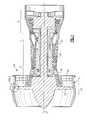
Figure 2 is an enlarged, cross-sectional side view of a fan case structure in a fan section of the gas turbine engine shown inFigure 1 . -
Figure 3 is a schematic, cross-sectional end view of an example fan section depicting an example flexible leaf member. -
Figures 4A-4B respectively illustrate first and second example top views of the flexible leaf member shown inFigure 3 . -
Figure 5 is a schematic, circumferential cross-sectional view of another example fan section depicting an example flexible leaf member. -
Figures 6A-6C respectively illustrate first, second and third example top views of the flexible leaf member shown inFigure 5 . -
Figure 7 is a schematic, circumferential cross-sectional view of yet another example fan section depicting an example flexible leaf member. -
Figures 8A-8C illustrate first and second examples of the flexible leaf member shown inFigure 7 . -
Figure 9 is a schematic, circumferential cross-sectional view of still another example fan section depicting an example flexible leaf member. -
Figures 10A-10B respectively illustrate first and second example top views of the flexible leaf member shown inFigure 9 . - An example
gas turbine engine 10 is schematically illustrated inFigure 1 . Thegas turbine engine 10 includes acompressor section 12, acombustor section 14 and aturbine section 16, which are arranged within acore housing 24. In the example illustrated, high pressure stages of thecompressor section 12 and theturbine section 16 are mounted on afirst shaft 20, which is rotatable about an axis A. Low pressure stages of thecompressor section 12 andturbine section 16 are mounted on asecond shaft 22 which is coaxial with thefirst shaft 20 and rotatable about the axis A. The first andsecond shafts core housing 24. - A
fan section 18 is arranged within afan case structure 30, which provides abypass flow path 28 between thefan case structure 30 and thecore housing 24. In the example illustrated, thefirst shaft 20 rotationally drives circumferentially arrangedfan blades 26 that provide flow through thebypass flow path 28. In one example, thefan blades 26 are constructed from an aluminum alloy. It should be understood that the configuration illustrated inFigure 1 is exemplary only, and the disclosure may be used in other configurations. Although a high bypass engine is illustrated, it should be understood that the disclosure also relates to other types of gas turbine engines, such as turbo jets. - Referring to
Figure 2 , thefan section 18 includes afan case structure 30 comprising multiple components in one example. Ahoneycomb structure 40, which may be constructed from aluminum, is supported radially inward from and on thefan case 32. Aseptum 42 is arranged radially inward from and supported by thehoneycomb structure 40. In one example, thefan case structure 30 includes acomposite fan case 32, which is constructed from carbon fiber and resin in one example. In one example, theseptum 42 is a composite structure constructed from fiberglass and resin. As can be appreciated, composite structures have relatively low coefficients of thermal expansion and are dimensionally stable throughout the various operating temperatures. - A continuous, ring-
shaped liner 44, which is an aluminum alloy, for example, is supported by thefan case structure 30, and in the example shown, by theseptum 42, using aflexible leaf member 46. Theseptum 42 may be constructed as part of the containment case body (fan case 32) and can be the same material. Theleaf member 46 is contained within aspace 48 provided between first andsecond surfaces septum 42 andliner 44. - The
liner 44 has a coefficient of thermal expansion that is substantially the same as the coefficient of thermal expansion of thefan blades 26 and substantially different than thefan case structure 30. In one example, thefan blades 26 andliner 44 have coefficients of thermal expansion that are within 1 x 10⁻⁶/°F (1.8 x 10⁻⁶/°C) of one another and are constructed from the same series aluminum alloy, which may be AM54027 in one example. In one example, the liner/fan blade coefficient of thermal expansion is greater than the fan case structure thermal expansion by at least 10 x 106/°F (18 x 10-6/°C) - The
liner 44 includes arub strip 36 that provides an abradable material immediately adjacent totips 34 of thefan blades 26, providing ablade tip clearance 38. It is desirable to maintain a desired radial blade tip clearance throughout various fan section operating temperatures. In one example, a desired radial tip clearance is about 0.030 in. at -65°F (0.76 mm at -54°C) ambient, which is typically encountered during cruise altitude. Thus, theleaf member 46 accommodates changes in a diameter 50 (only radial lead line is shown inFigure 2 ) of theliner 44 as theliner 44 expands and contracts during operation. - In the examples shown in
Figure 3 , theleaf member 46 is an annular sheet of material, such as metal, for example, aluminum or steel. Theleaf member 46 hasundulations providing peaks 56 andvalleys 58 respectively secured to theseptum 42 andliner 44 byfastening elements 62. In one example, thefastening elements 62 may be strips of adhesive that secure and affix first andsecond portions peaks 56 andvalleys 58, to the first andsecond surfaces - Referring to
Figures 4A-4B , lightened leaf members 146, 246 may includeperforations septum 42 andliner 44. - Another
example leaf member 346 is shown inFigures 5 and 6A . Theleaf member 346 includesfirst portions 166 arranged at opposing axial ends and asecond portion 168 centrally located on theleaf member 346. The first andsecond portions septum 42 and theliner 44, for example. To provide increased flexibility, the first portions includethin legs 70 spaced circumferentially about the perimeter of theleaf member 346. Eachleg 70 terminates in awidened foot 72 that is secured to theliner 42. Thelegs 70 may extend axially (Figure 6A ) or may be angled in a circumferential direction that corresponds to a blade rub direction, as shown inFigure 6B . In this manner, thelegs 170, havingfeet 172, may absorb the circumferential load in a blade rub event. - In the example shown in
Figure 6C , theleaf member 546 includes discrete, axially extending bands that provide the opposingfirst portions 366 and centralsecond portion 368. The bands are circumferentially spaced about theseptum 42 andliner 44 to provide a geometry similar to that illustrated inFigure 5 . - Referring to
Figures 7-8B , theleaf member 646 includesstraps intersection 76 to provide an X-shaped pattern. Thestraps second portion septum 42 andliner 44 in the example shown. Anotherexample leaf member 746 is shown inFigure 8C . Theleaf member 746 is formed from an annular member that includesnotches 78 andapertures 80 that provide the X-shaped pattern having first andsecond portions Figures 7-8B . - Referring to
Figures 9-10A , an arrangement of discrete circumferentially arrangedleaf members 846 is illustrated. Eachleaf members 846 is oriented in a circumferential direction, as shown inFigure 9 , with the first andsecond portions septum 42 andliner 44. The circumferential direction corresponds to a blade rub direction.Figure 10B depicts aleaf member 846 with first andsecond portions - Although an example embodiment has been disclosed, a worker of ordinary skill in this art would recognize that certain modifications would come within the scope of the claims. For that reason, the following claims should be studied to determine their true scope and content. For example, it should be understood that the leaf member may be used in other gas turbine sections, in addition to the fan section examples disclosed.
Claims (15)
- A section (18) of a gas turbine (10) engine comprising:a case structure (30) having a first coefficient of thermal expansion;a continuous ring-shaped liner (44) having a second coefficient of thermal expansion that is substantially different than the first coefficient of thermal expansion; anda flexible leaf member (46; 146; 246; 346; 446; 546; 646; 746; 846; 946) having first and second portions mechanically affixed respectively to the liner (44) to the case structure (30), the leaf member (46; 146; 246; 346; 446; 546; 646; 746; 846; 946) configured to accommodate diametrical change in the liner (44) throughout various section-operating temperatures.
- The section (18) according to claim 1, further comprising a blade (26) arranged within the case structure (30) and having a third coefficient of thermal expansion that is substantially similar to the second coefficient of thermal expansion, the continuous ring-shaped liner (44) surrounding the blade (26) and a desired radial tip clearance (38) between the liner (44) and the blade (26), and the flexible leaf member (46; 146; 246; 346; 446; 546; 646; 746; 846; 946) maintaining the desired radial tip clearance (38) throughout various section-operating temperatures.
- The section (180 according to claim 2, wherein the case structure (30) includes a composite case (32), and the blade (26) is a metallic fan blade.
- The section (18) according to claim 3, wherein the case structure (30) includes a honeycomb structure (40) operatively connected radially inward of and to the composite case (32).
- The section (18) according to claim 4, wherein the case structure (30) includes a composite septum (42) interconnecting the leaf member (46; 146; 246; 346; 446; 546; 646; 746; 846; 946) and the honeycomb structure (40).
- The section (18) according to any of claims 2 to 5, comprising a rub strip (36) supported on and radially inward of the liner (44) between the liner (44) and the blade (26).
- The section (18) according to any of claims 2 to 6, wherein the blade (26) and the liner (44) are constructed from the same series aluminum alloy.
- The section (18) according to any preceding claim, wherein the leaf member (46; 146; 246; 346; 446; 546; 646; 746; 846; 946) includes first (66; 166; 266; 366; 466; 566; 666; 766) and second portions (68; 168; 268; 368; 468; 568; 668; 768) respectively affixed to the liner (44) and the case structure (30).
- The section (18) according to claim 8, wherein the first and second portions (666; 668; 766; 768) are provided on opposing ends of the leaf member (846; 946).
- The section (18) according to claim 8, wherein the first portion (166; 266; 366) is provided on an end of the leaf member (346; 446; 546), and the second portion (168; 268; 368) is provided on a central part of the leaf member (346; 446; 546).
- The section (18) according to claim 10, wherein the first portion (166; 266) includes a leg (70; 170) and a foot (72; 172), the end provided by the foot (72; 172).
- The section (18) according to claim 11, wherein the leg (170) is angled in a circumferential direction corresponding to a blade rub direction.
- The section (18) according to claim 8, wherein the leaf member (646) includes overlapping straps (82; 84) arranged generally in an X-shaped pattern, the straps (82; 84) providing the first and second portions (466; 468).
- The section (18) according to claim 8, wherein the leaf member (46; 146; 246) is provided with an annular structure with undulations about its circumference, the undulations providing peaks (56) and valleys (58) corresponding to the first and second portions (66, 68).
- The section (18) according to claim 8 or 9, wherein the leaf member (846) includes discrete leafs separated from one another and oriented in a circumferential direction corresponding to a blade rub direction.
Applications Claiming Priority (1)
| Application Number | Priority Date | Filing Date | Title |
|---|---|---|---|
| US13/366,424 US9255489B2 (en) | 2012-02-06 | 2012-02-06 | Clearance control for gas turbine engine section |
Publications (3)
| Publication Number | Publication Date |
|---|---|
| EP2623723A2 true EP2623723A2 (en) | 2013-08-07 |
| EP2623723A3 EP2623723A3 (en) | 2017-05-03 |
| EP2623723B1 EP2623723B1 (en) | 2019-09-11 |
Family
ID=47561403
Family Applications (1)
| Application Number | Title | Priority Date | Filing Date |
|---|---|---|---|
| EP13151323.6A Active EP2623723B1 (en) | 2012-02-06 | 2013-01-15 | Clearance control system for a gas turbine engine section |
Country Status (2)
| Country | Link |
|---|---|
| US (1) | US9255489B2 (en) |
| EP (1) | EP2623723B1 (en) |
Cited By (4)
| Publication number | Priority date | Publication date | Assignee | Title |
|---|---|---|---|---|
| WO2017158295A1 (en) * | 2016-03-15 | 2017-09-21 | Safran Aircraft Engines | Turbofan |
| EP3090128A4 (en) * | 2013-12-06 | 2017-10-18 | United Technologies Corporation | Aluminum alloy airfoil with designed crystallographic texture |
| EP3597872A1 (en) * | 2018-07-16 | 2020-01-22 | United Technologies Corporation | Fan case assembly for a gas turbine engine |
| FR3085179A1 (en) * | 2018-08-21 | 2020-02-28 | Safran Aircraft Engines | FLEXIBLE HOUSING |
Families Citing this family (21)
| Publication number | Priority date | Publication date | Assignee | Title |
|---|---|---|---|---|
| US9651059B2 (en) * | 2012-12-27 | 2017-05-16 | United Technologies Corporation | Adhesive pattern for fan case conformable liner |
| DE102015217078A1 (en) * | 2015-09-07 | 2017-03-09 | MTU Aero Engines AG | Device for limiting a flow channel of a turbomachine |
| US10677260B2 (en) * | 2017-02-21 | 2020-06-09 | General Electric Company | Turbine engine and method of manufacturing |
| US10815816B2 (en) | 2018-09-24 | 2020-10-27 | General Electric Company | Containment case active clearance control structure |
| US11236631B2 (en) * | 2018-11-19 | 2022-02-01 | Rolls-Royce North American Technologies Inc. | Mechanical iris tip clearance control |
| WO2022208801A1 (en) * | 2021-03-31 | 2022-10-06 | 川崎重工業株式会社 | Fan case assembly for turbofan engine |
| US12338738B2 (en) | 2022-07-05 | 2025-06-24 | General Electric Company | Variable flowpath casings for blade tip clearance control |
| US12012859B2 (en) | 2022-07-11 | 2024-06-18 | General Electric Company | Variable flowpath casings for blade tip clearance control |
| US11808157B1 (en) | 2022-07-13 | 2023-11-07 | General Electric Company | Variable flowpath casings for blade tip clearance control |
| US12006829B1 (en) | 2023-02-16 | 2024-06-11 | General Electric Company | Seal member support system for a gas turbine engine |
| US12486779B2 (en) | 2023-03-08 | 2025-12-02 | General Electric Company | Seal support assembly for a turbine engine |
| US12116896B1 (en) | 2023-03-24 | 2024-10-15 | General Electric Company | Seal support assembly for a turbine engine |
| US12595745B2 (en) | 2023-03-24 | 2026-04-07 | General Electric Company | Seal support assembly for a turbine engine |
| US12372002B2 (en) | 2023-03-24 | 2025-07-29 | General Electric Company | Seal support assembly for a turbine engine |
| US12416243B2 (en) | 2023-03-24 | 2025-09-16 | General Electric Company | Seal support assembly for a turbine engine |
| US12241375B2 (en) | 2023-03-24 | 2025-03-04 | General Electric Company | Seal support assembly for a turbine engine |
| US12421861B2 (en) | 2023-03-24 | 2025-09-23 | General Electric Company | Seal support assembly for a turbine engine |
| US12215587B2 (en) | 2023-03-24 | 2025-02-04 | General Electric Company | Seal support assembly for a turbine engine |
| US12215588B2 (en) | 2023-03-27 | 2025-02-04 | General Electric Company | Seal assembly for a gas turbine engine |
| US12326089B2 (en) | 2023-04-24 | 2025-06-10 | General Electric Company | Seal assembly for a gas turbine engine |
| US12297741B2 (en) | 2023-06-19 | 2025-05-13 | General Electric Company | Rapid active clearance control system of inter stage and mid-seals |
Family Cites Families (21)
| Publication number | Priority date | Publication date | Assignee | Title |
|---|---|---|---|---|
| FR2576637B1 (en) * | 1985-01-30 | 1988-11-18 | Snecma | GAS TURBINE RING. |
| GB2249356B (en) | 1990-11-01 | 1995-01-18 | Rolls Royce Plc | Shroud liners |
| US5456576A (en) * | 1994-08-31 | 1995-10-10 | United Technologies Corporation | Dynamic control of tip clearance |
| US5545007A (en) * | 1994-11-25 | 1996-08-13 | United Technologies Corp. | Engine blade clearance control system with piezoelectric actuator |
| US6382905B1 (en) | 2000-04-28 | 2002-05-07 | General Electric Company | Fan casing liner support |
| US6547522B2 (en) | 2001-06-18 | 2003-04-15 | General Electric Company | Spring-backed abradable seal for turbomachinery |
| US6732502B2 (en) * | 2002-03-01 | 2004-05-11 | General Electric Company | Counter rotating aircraft gas turbine engine with high overall pressure ratio compressor |
| US6733233B2 (en) * | 2002-04-26 | 2004-05-11 | Pratt & Whitney Canada Corp. | Attachment of a ceramic shroud in a metal housing |
| US6935836B2 (en) | 2002-06-05 | 2005-08-30 | Allison Advanced Development Company | Compressor casing with passive tip clearance control and endwall ovalization control |
| US6877952B2 (en) | 2002-09-09 | 2005-04-12 | Florida Turbine Technologies, Inc | Passive clearance control |
| GB0308147D0 (en) | 2003-04-09 | 2003-05-14 | Rolls Royce Plc | A seal |
| US7229246B2 (en) | 2004-09-30 | 2007-06-12 | General Electric Company | Compliant seal and system and method thereof |
| US7771160B2 (en) | 2006-08-10 | 2010-08-10 | United Technologies Corporation | Ceramic shroud assembly |
| US9127565B2 (en) | 2008-04-16 | 2015-09-08 | Siemens Energy, Inc. | Apparatus comprising a CMC-comprising body and compliant porous element preloaded within an outer metal shell |
| GB2462581B (en) * | 2008-06-25 | 2010-11-24 | Rolls Royce Plc | Rotor path arrangements |
| GB0914679D0 (en) * | 2009-08-24 | 2009-09-30 | Rolls Royce Plc | Adjustable fan case liner and mounting method |
| US8079807B2 (en) * | 2010-01-29 | 2011-12-20 | General Electric Company | Mounting apparatus for low-ductility turbine shroud |
| US8784052B2 (en) * | 2010-05-10 | 2014-07-22 | Hamilton Sundstrand Corporation | Ceramic gas turbine shroud |
| US8500390B2 (en) * | 2010-05-20 | 2013-08-06 | Pratt & Whitney Canada Corp. | Fan case with rub elements |
| US8834106B2 (en) * | 2011-06-01 | 2014-09-16 | United Technologies Corporation | Seal assembly for gas turbine engine |
| US8985938B2 (en) * | 2011-12-13 | 2015-03-24 | United Technologies Corporation | Fan blade tip clearance control via Z-bands |
-
2012
- 2012-02-06 US US13/366,424 patent/US9255489B2/en active Active
-
2013
- 2013-01-15 EP EP13151323.6A patent/EP2623723B1/en active Active
Cited By (10)
| Publication number | Priority date | Publication date | Assignee | Title |
|---|---|---|---|---|
| EP3090128A4 (en) * | 2013-12-06 | 2017-10-18 | United Technologies Corporation | Aluminum alloy airfoil with designed crystallographic texture |
| US10370984B2 (en) | 2013-12-06 | 2019-08-06 | United Technologies Corporation | Aluminum alloy airfoil with designed crystallographic texture |
| WO2017158295A1 (en) * | 2016-03-15 | 2017-09-21 | Safran Aircraft Engines | Turbofan |
| FR3048999A1 (en) * | 2016-03-15 | 2017-09-22 | Snecma | TURBOREACTOR LOW GAME BETWEEN BLOWER AND BLOWER HOUSING |
| CN108779683A (en) * | 2016-03-15 | 2018-11-09 | 赛峰飞机发动机公司 | turbofan engine |
| CN108779683B (en) * | 2016-03-15 | 2022-02-11 | 赛峰飞机发动机公司 | Gas turbine engine with minimal tolerance between fan and fan casing |
| US11313325B2 (en) | 2016-03-15 | 2022-04-26 | Safran Aircraft Engines | Gas turbine engine with minimal tolerance between the fan and the fan casing |
| EP3597872A1 (en) * | 2018-07-16 | 2020-01-22 | United Technologies Corporation | Fan case assembly for a gas turbine engine |
| US10724403B2 (en) | 2018-07-16 | 2020-07-28 | Raytheon Technologies Corporation | Fan case assembly for gas turbine engine |
| FR3085179A1 (en) * | 2018-08-21 | 2020-02-28 | Safran Aircraft Engines | FLEXIBLE HOUSING |
Also Published As
| Publication number | Publication date |
|---|---|
| US9255489B2 (en) | 2016-02-09 |
| EP2623723A3 (en) | 2017-05-03 |
| EP2623723B1 (en) | 2019-09-11 |
| US20130202418A1 (en) | 2013-08-08 |
Similar Documents
| Publication | Publication Date | Title |
|---|---|---|
| EP2623723B1 (en) | Clearance control system for a gas turbine engine section | |
| EP2775104B1 (en) | Conformal liner for gas turbine engine fan section | |
| US10138734B2 (en) | Turbine ring for a turbomachine | |
| US9708922B1 (en) | Seal ring for gas turbine engines | |
| US8794908B2 (en) | Stator stage for turbomachine compressor | |
| EP3502497B1 (en) | Flexible preloaded ball bearing assembly | |
| EP2615256B1 (en) | Spring "t" seal of a gas turbine | |
| EP3090140B1 (en) | Blade outer air seal with secondary air sealing | |
| US20150030443A1 (en) | Split damped outer shroud for gas turbine engine stator arrays | |
| US9670791B2 (en) | Flexible finger seal for sealing a gap between turbine engine components | |
| US9644640B2 (en) | Compressor nozzle stage for a turbine engine | |
| EP3012494B1 (en) | Sliding seal | |
| EP3290647B1 (en) | A gas turbine seal sub-assembly | |
| WO2017007529A1 (en) | Compliant flexural inner shroud for joint assemblies | |
| EP3409885B1 (en) | Deflection spring seal | |
| US20150369409A1 (en) | Low leakage duct segment using expansion joint assembly | |
| EP3628823B1 (en) | Seal arrangement | |
| US20180156369A1 (en) | Compliant flexural inner shroud for bellowed spherical flex-joint assemblies for reduced dynamic rotational stiffness | |
| US10677260B2 (en) | Turbine engine and method of manufacturing | |
| US10472987B2 (en) | Heat shield for a casing | |
| US9651059B2 (en) | Adhesive pattern for fan case conformable liner | |
| EP3064710B1 (en) | Airfoil assembly with floating wall sectors |
Legal Events
| Date | Code | Title | Description |
|---|---|---|---|
| PUAI | Public reference made under article 153(3) epc to a published international application that has entered the european phase |
Free format text: ORIGINAL CODE: 0009012 |
|
| AK | Designated contracting states |
Kind code of ref document: A2 Designated state(s): AL AT BE BG CH CY CZ DE DK EE ES FI FR GB GR HR HU IE IS IT LI LT LU LV MC MK MT NL NO PL PT RO RS SE SI SK SM TR |
|
| AX | Request for extension of the european patent |
Extension state: BA ME |
|
| RAP1 | Party data changed (applicant data changed or rights of an application transferred) |
Owner name: UNITED TECHNOLOGIES CORPORATION |
|
| PUAL | Search report despatched |
Free format text: ORIGINAL CODE: 0009013 |
|
| AK | Designated contracting states |
Kind code of ref document: A3 Designated state(s): AL AT BE BG CH CY CZ DE DK EE ES FI FR GB GR HR HU IE IS IT LI LT LU LV MC MK MT NL NO PL PT RO RS SE SI SK SM TR |
|
| AX | Request for extension of the european patent |
Extension state: BA ME |
|
| RIC1 | Information provided on ipc code assigned before grant |
Ipc: F01D 11/12 20060101AFI20170327BHEP Ipc: F01D 11/16 20060101ALI20170327BHEP Ipc: F02K 3/06 20060101ALN20170327BHEP |
|
| STAA | Information on the status of an ep patent application or granted ep patent |
Free format text: STATUS: REQUEST FOR EXAMINATION WAS MADE |
|
| 17P | Request for examination filed |
Effective date: 20171103 |
|
| RBV | Designated contracting states (corrected) |
Designated state(s): AL AT BE BG CH CY CZ DE DK EE ES FI FR GB GR HR HU IE IS IT LI LT LU LV MC MK MT NL NO PL PT RO RS SE SI SK SM TR |
|
| GRAP | Despatch of communication of intention to grant a patent |
Free format text: ORIGINAL CODE: EPIDOSNIGR1 |
|
| STAA | Information on the status of an ep patent application or granted ep patent |
Free format text: STATUS: GRANT OF PATENT IS INTENDED |
|
| RIC1 | Information provided on ipc code assigned before grant |
Ipc: F02K 3/06 20060101ALN20190219BHEP Ipc: F01D 11/12 20060101AFI20190219BHEP Ipc: F01D 11/16 20060101ALI20190219BHEP |
|
| INTG | Intention to grant announced |
Effective date: 20190319 |
|
| GRAS | Grant fee paid |
Free format text: ORIGINAL CODE: EPIDOSNIGR3 |
|
| GRAA | (expected) grant |
Free format text: ORIGINAL CODE: 0009210 |
|
| STAA | Information on the status of an ep patent application or granted ep patent |
Free format text: STATUS: THE PATENT HAS BEEN GRANTED |
|
| AK | Designated contracting states |
Kind code of ref document: B1 Designated state(s): AL AT BE BG CH CY CZ DE DK EE ES FI FR GB GR HR HU IE IS IT LI LT LU LV MC MK MT NL NO PL PT RO RS SE SI SK SM TR |
|
| REG | Reference to a national code |
Ref country code: GB Ref legal event code: FG4D |
|
| REG | Reference to a national code |
Ref country code: CH Ref legal event code: EP |
|
| REG | Reference to a national code |
Ref country code: AT Ref legal event code: REF Ref document number: 1178716 Country of ref document: AT Kind code of ref document: T Effective date: 20190915 |
|
| REG | Reference to a national code |
Ref country code: DE Ref legal event code: R096 Ref document number: 602013060253 Country of ref document: DE |
|
| REG | Reference to a national code |
Ref country code: IE Ref legal event code: FG4D |
|
| REG | Reference to a national code |
Ref country code: NL Ref legal event code: MP Effective date: 20190911 |
|
| REG | Reference to a national code |
Ref country code: LT Ref legal event code: MG4D |
|
| PG25 | Lapsed in a contracting state [announced via postgrant information from national office to epo] |
Ref country code: SE Free format text: LAPSE BECAUSE OF FAILURE TO SUBMIT A TRANSLATION OF THE DESCRIPTION OR TO PAY THE FEE WITHIN THE PRESCRIBED TIME-LIMIT Effective date: 20190911 Ref country code: NO Free format text: LAPSE BECAUSE OF FAILURE TO SUBMIT A TRANSLATION OF THE DESCRIPTION OR TO PAY THE FEE WITHIN THE PRESCRIBED TIME-LIMIT Effective date: 20191211 Ref country code: FI Free format text: LAPSE BECAUSE OF FAILURE TO SUBMIT A TRANSLATION OF THE DESCRIPTION OR TO PAY THE FEE WITHIN THE PRESCRIBED TIME-LIMIT Effective date: 20190911 Ref country code: HR Free format text: LAPSE BECAUSE OF FAILURE TO SUBMIT A TRANSLATION OF THE DESCRIPTION OR TO PAY THE FEE WITHIN THE PRESCRIBED TIME-LIMIT Effective date: 20190911 Ref country code: BG Free format text: LAPSE BECAUSE OF FAILURE TO SUBMIT A TRANSLATION OF THE DESCRIPTION OR TO PAY THE FEE WITHIN THE PRESCRIBED TIME-LIMIT Effective date: 20191211 Ref country code: LT Free format text: LAPSE BECAUSE OF FAILURE TO SUBMIT A TRANSLATION OF THE DESCRIPTION OR TO PAY THE FEE WITHIN THE PRESCRIBED TIME-LIMIT Effective date: 20190911 |
|
| PG25 | Lapsed in a contracting state [announced via postgrant information from national office to epo] |
Ref country code: ES Free format text: LAPSE BECAUSE OF FAILURE TO SUBMIT A TRANSLATION OF THE DESCRIPTION OR TO PAY THE FEE WITHIN THE PRESCRIBED TIME-LIMIT Effective date: 20190911 Ref country code: GR Free format text: LAPSE BECAUSE OF FAILURE TO SUBMIT A TRANSLATION OF THE DESCRIPTION OR TO PAY THE FEE WITHIN THE PRESCRIBED TIME-LIMIT Effective date: 20191212 Ref country code: AL Free format text: LAPSE BECAUSE OF FAILURE TO SUBMIT A TRANSLATION OF THE DESCRIPTION OR TO PAY THE FEE WITHIN THE PRESCRIBED TIME-LIMIT Effective date: 20190911 Ref country code: LV Free format text: LAPSE BECAUSE OF FAILURE TO SUBMIT A TRANSLATION OF THE DESCRIPTION OR TO PAY THE FEE WITHIN THE PRESCRIBED TIME-LIMIT Effective date: 20190911 Ref country code: RS Free format text: LAPSE BECAUSE OF FAILURE TO SUBMIT A TRANSLATION OF THE DESCRIPTION OR TO PAY THE FEE WITHIN THE PRESCRIBED TIME-LIMIT Effective date: 20190911 |
|
| REG | Reference to a national code |
Ref country code: AT Ref legal event code: MK05 Ref document number: 1178716 Country of ref document: AT Kind code of ref document: T Effective date: 20190911 |
|
| PG25 | Lapsed in a contracting state [announced via postgrant information from national office to epo] |
Ref country code: PT Free format text: LAPSE BECAUSE OF FAILURE TO SUBMIT A TRANSLATION OF THE DESCRIPTION OR TO PAY THE FEE WITHIN THE PRESCRIBED TIME-LIMIT Effective date: 20200113 Ref country code: RO Free format text: LAPSE BECAUSE OF FAILURE TO SUBMIT A TRANSLATION OF THE DESCRIPTION OR TO PAY THE FEE WITHIN THE PRESCRIBED TIME-LIMIT Effective date: 20190911 Ref country code: PL Free format text: LAPSE BECAUSE OF FAILURE TO SUBMIT A TRANSLATION OF THE DESCRIPTION OR TO PAY THE FEE WITHIN THE PRESCRIBED TIME-LIMIT Effective date: 20190911 Ref country code: NL Free format text: LAPSE BECAUSE OF FAILURE TO SUBMIT A TRANSLATION OF THE DESCRIPTION OR TO PAY THE FEE WITHIN THE PRESCRIBED TIME-LIMIT Effective date: 20190911 Ref country code: IT Free format text: LAPSE BECAUSE OF FAILURE TO SUBMIT A TRANSLATION OF THE DESCRIPTION OR TO PAY THE FEE WITHIN THE PRESCRIBED TIME-LIMIT Effective date: 20190911 Ref country code: AT Free format text: LAPSE BECAUSE OF FAILURE TO SUBMIT A TRANSLATION OF THE DESCRIPTION OR TO PAY THE FEE WITHIN THE PRESCRIBED TIME-LIMIT Effective date: 20190911 Ref country code: EE Free format text: LAPSE BECAUSE OF FAILURE TO SUBMIT A TRANSLATION OF THE DESCRIPTION OR TO PAY THE FEE WITHIN THE PRESCRIBED TIME-LIMIT Effective date: 20190911 |
|
| PG25 | Lapsed in a contracting state [announced via postgrant information from national office to epo] |
Ref country code: CZ Free format text: LAPSE BECAUSE OF FAILURE TO SUBMIT A TRANSLATION OF THE DESCRIPTION OR TO PAY THE FEE WITHIN THE PRESCRIBED TIME-LIMIT Effective date: 20190911 Ref country code: SM Free format text: LAPSE BECAUSE OF FAILURE TO SUBMIT A TRANSLATION OF THE DESCRIPTION OR TO PAY THE FEE WITHIN THE PRESCRIBED TIME-LIMIT Effective date: 20190911 Ref country code: SK Free format text: LAPSE BECAUSE OF FAILURE TO SUBMIT A TRANSLATION OF THE DESCRIPTION OR TO PAY THE FEE WITHIN THE PRESCRIBED TIME-LIMIT Effective date: 20190911 Ref country code: IS Free format text: LAPSE BECAUSE OF FAILURE TO SUBMIT A TRANSLATION OF THE DESCRIPTION OR TO PAY THE FEE WITHIN THE PRESCRIBED TIME-LIMIT Effective date: 20200224 |
|
| REG | Reference to a national code |
Ref country code: DE Ref legal event code: R097 Ref document number: 602013060253 Country of ref document: DE |
|
| PLBE | No opposition filed within time limit |
Free format text: ORIGINAL CODE: 0009261 |
|
| STAA | Information on the status of an ep patent application or granted ep patent |
Free format text: STATUS: NO OPPOSITION FILED WITHIN TIME LIMIT |
|
| PG2D | Information on lapse in contracting state deleted |
Ref country code: IS |
|
| PG25 | Lapsed in a contracting state [announced via postgrant information from national office to epo] |
Ref country code: DK Free format text: LAPSE BECAUSE OF FAILURE TO SUBMIT A TRANSLATION OF THE DESCRIPTION OR TO PAY THE FEE WITHIN THE PRESCRIBED TIME-LIMIT Effective date: 20190911 Ref country code: IS Free format text: LAPSE BECAUSE OF FAILURE TO SUBMIT A TRANSLATION OF THE DESCRIPTION OR TO PAY THE FEE WITHIN THE PRESCRIBED TIME-LIMIT Effective date: 20200112 |
|
| 26N | No opposition filed |
Effective date: 20200615 |
|
| PG25 | Lapsed in a contracting state [announced via postgrant information from national office to epo] |
Ref country code: MC Free format text: LAPSE BECAUSE OF FAILURE TO SUBMIT A TRANSLATION OF THE DESCRIPTION OR TO PAY THE FEE WITHIN THE PRESCRIBED TIME-LIMIT Effective date: 20190911 Ref country code: SI Free format text: LAPSE BECAUSE OF FAILURE TO SUBMIT A TRANSLATION OF THE DESCRIPTION OR TO PAY THE FEE WITHIN THE PRESCRIBED TIME-LIMIT Effective date: 20190911 |
|
| REG | Reference to a national code |
Ref country code: CH Ref legal event code: PL |
|
| REG | Reference to a national code |
Ref country code: BE Ref legal event code: MM Effective date: 20200131 |
|
| PG25 | Lapsed in a contracting state [announced via postgrant information from national office to epo] |
Ref country code: LU Free format text: LAPSE BECAUSE OF NON-PAYMENT OF DUE FEES Effective date: 20200115 |
|
| PG25 | Lapsed in a contracting state [announced via postgrant information from national office to epo] |
Ref country code: BE Free format text: LAPSE BECAUSE OF NON-PAYMENT OF DUE FEES Effective date: 20200131 Ref country code: CH Free format text: LAPSE BECAUSE OF NON-PAYMENT OF DUE FEES Effective date: 20200131 Ref country code: LI Free format text: LAPSE BECAUSE OF NON-PAYMENT OF DUE FEES Effective date: 20200131 |
|
| PG25 | Lapsed in a contracting state [announced via postgrant information from national office to epo] |
Ref country code: IE Free format text: LAPSE BECAUSE OF NON-PAYMENT OF DUE FEES Effective date: 20200115 |
|
| PG25 | Lapsed in a contracting state [announced via postgrant information from national office to epo] |
Ref country code: TR Free format text: LAPSE BECAUSE OF FAILURE TO SUBMIT A TRANSLATION OF THE DESCRIPTION OR TO PAY THE FEE WITHIN THE PRESCRIBED TIME-LIMIT Effective date: 20190911 Ref country code: MT Free format text: LAPSE BECAUSE OF FAILURE TO SUBMIT A TRANSLATION OF THE DESCRIPTION OR TO PAY THE FEE WITHIN THE PRESCRIBED TIME-LIMIT Effective date: 20190911 Ref country code: CY Free format text: LAPSE BECAUSE OF FAILURE TO SUBMIT A TRANSLATION OF THE DESCRIPTION OR TO PAY THE FEE WITHIN THE PRESCRIBED TIME-LIMIT Effective date: 20190911 |
|
| PG25 | Lapsed in a contracting state [announced via postgrant information from national office to epo] |
Ref country code: MK Free format text: LAPSE BECAUSE OF FAILURE TO SUBMIT A TRANSLATION OF THE DESCRIPTION OR TO PAY THE FEE WITHIN THE PRESCRIBED TIME-LIMIT Effective date: 20190911 |
|
| REG | Reference to a national code |
Ref country code: DE Ref legal event code: R081 Ref document number: 602013060253 Country of ref document: DE Owner name: RAYTHEON TECHNOLOGIES CORPORATION (N.D.GES.D.S, US Free format text: FORMER OWNER: UNITED TECHNOLOGIES CORP., FARMINGTON, CONN., US Ref country code: DE Ref legal event code: R081 Ref document number: 602013060253 Country of ref document: DE Owner name: RTX CORPORATION (N.D.GES.D. STAATES DELAWARE),, US Free format text: FORMER OWNER: UNITED TECHNOLOGIES CORP., FARMINGTON, CONN., US |
|
| P01 | Opt-out of the competence of the unified patent court (upc) registered |
Effective date: 20230520 |
|
| REG | Reference to a national code |
Ref country code: DE Ref legal event code: R081 Ref document number: 602013060253 Country of ref document: DE Owner name: RTX CORPORATION (N.D.GES.D. STAATES DELAWARE),, US Free format text: FORMER OWNER: RAYTHEON TECHNOLOGIES CORPORATION (N.D.GES.D.STAATES DELAWARE), ARLINGTON, VA, US |
|
| PGFP | Annual fee paid to national office [announced via postgrant information from national office to epo] |
Ref country code: GB Payment date: 20251220 Year of fee payment: 14 |
|
| PGFP | Annual fee paid to national office [announced via postgrant information from national office to epo] |
Ref country code: FR Payment date: 20251217 Year of fee payment: 14 |
|
| PGFP | Annual fee paid to national office [announced via postgrant information from national office to epo] |
Ref country code: DE Payment date: 20251217 Year of fee payment: 14 |