EP2623721A2 - Steam turbine with single shell casing, drum rotor, and individual nozzle rings - Google Patents
Steam turbine with single shell casing, drum rotor, and individual nozzle rings Download PDFInfo
- Publication number
- EP2623721A2 EP2623721A2 EP13152583.4A EP13152583A EP2623721A2 EP 2623721 A2 EP2623721 A2 EP 2623721A2 EP 13152583 A EP13152583 A EP 13152583A EP 2623721 A2 EP2623721 A2 EP 2623721A2
- Authority
- EP
- European Patent Office
- Prior art keywords
- section
- steam turbine
- condenser
- nozzle ring
- shell casing
- Prior art date
- Legal status (The legal status is an assumption and is not a legal conclusion. Google has not performed a legal analysis and makes no representation as to the accuracy of the status listed.)
- Granted
Links
Images




Classifications
-
- F—MECHANICAL ENGINEERING; LIGHTING; HEATING; WEAPONS; BLASTING
- F01—MACHINES OR ENGINES IN GENERAL; ENGINE PLANTS IN GENERAL; STEAM ENGINES
- F01D—NON-POSITIVE DISPLACEMENT MACHINES OR ENGINES, e.g. STEAM TURBINES
- F01D25/00—Component parts, details, or accessories, not provided for in, or of interest apart from, other groups
- F01D25/24—Casings; Casing parts, e.g. diaphragms, casing fastenings
- F01D25/246—Fastening of diaphragms or stator-rings
-
- F—MECHANICAL ENGINEERING; LIGHTING; HEATING; WEAPONS; BLASTING
- F01—MACHINES OR ENGINES IN GENERAL; ENGINE PLANTS IN GENERAL; STEAM ENGINES
- F01D—NON-POSITIVE DISPLACEMENT MACHINES OR ENGINES, e.g. STEAM TURBINES
- F01D25/00—Component parts, details, or accessories, not provided for in, or of interest apart from, other groups
- F01D25/24—Casings; Casing parts, e.g. diaphragms, casing fastenings
- F01D25/26—Double casings; Measures against temperature strain in casings
-
- F—MECHANICAL ENGINEERING; LIGHTING; HEATING; WEAPONS; BLASTING
- F01—MACHINES OR ENGINES IN GENERAL; ENGINE PLANTS IN GENERAL; STEAM ENGINES
- F01D—NON-POSITIVE DISPLACEMENT MACHINES OR ENGINES, e.g. STEAM TURBINES
- F01D9/00—Stators
- F01D9/02—Nozzles; Nozzle boxes; Stator blades; Guide conduits, e.g. individual nozzles
- F01D9/04—Nozzles; Nozzle boxes; Stator blades; Guide conduits, e.g. individual nozzles forming ring or sector
- F01D9/042—Nozzles; Nozzle boxes; Stator blades; Guide conduits, e.g. individual nozzles forming ring or sector fixing blades to stators
-
- F—MECHANICAL ENGINEERING; LIGHTING; HEATING; WEAPONS; BLASTING
- F01—MACHINES OR ENGINES IN GENERAL; ENGINE PLANTS IN GENERAL; STEAM ENGINES
- F01K—STEAM ENGINE PLANTS; STEAM ACCUMULATORS; ENGINE PLANTS NOT OTHERWISE PROVIDED FOR; ENGINES USING SPECIAL WORKING FLUIDS OR CYCLES
- F01K9/00—Plants characterised by condensers arranged or modified to co-operate with the engines
-
- F—MECHANICAL ENGINEERING; LIGHTING; HEATING; WEAPONS; BLASTING
- F05—INDEXING SCHEMES RELATING TO ENGINES OR PUMPS IN VARIOUS SUBCLASSES OF CLASSES F01-F04
- F05D—INDEXING SCHEME FOR ASPECTS RELATING TO NON-POSITIVE-DISPLACEMENT MACHINES OR ENGINES, GAS-TURBINES OR JET-PROPULSION PLANTS
- F05D2220/00—Application
- F05D2220/30—Application in turbines
- F05D2220/31—Application in turbines in steam turbines
Definitions
- Embodiments of the invention relate generally to steam turbines and, more particularly, to a steam turbine having an Intermediate Pressure (IP) section with a single shell casing.
- IP Intermediate Pressure
- a steam turbine with a drum rotor utilizing individual nozzle ring assemblies in the IP section incased by a single shell is disclosed herein.
- a steam turbine has a high pressure (HP) section with a double shell drum and an intermediate pressure (IP) section with a single shell drum, with the IP section including a plurality of individual nozzle ring assemblies axially spaced along the single shell casing, such that each nozzle ring assembly surrounds the drum rotor.
- a low pressure section (LP) of the steam turbine can have a single-flow or dual-flow connection to a condenser, and the condenser can be positioned to the side, vertically below, or axially aligned with the LP section.
- a first aspect of the invention provides a steam turbine including an intermediate pressure (IP) section having a single shell casing, wherein the IP section includes: a drum rotor; and a plurality of nozzle ring assemblies axially spaced along the single shell casing, such that each nozzle ring assembly surrounds the drum rotor, and wherein each nozzle ring assembly includes: a supporting ring; and at least one set of individual nozzles coupled to the supporting ring.
- IP intermediate pressure
- a second aspect of the invention provides a steam turbine comprising: a high pressure (HP) section having a double shell casing; an intermediate pressure (IP) section fluidly connected to the HP section, wherein the IP section has a single shell casing, and wherein the IP section includes: a drum rotor; and a plurality of nozzle ring assemblies axially spaced along the single shell casing, such that each nozzle ring assembly surrounds the drum rotor, and wherein each nozzle ring assembly includes: a supporting ring; and at least one set of individual nozzles coupled to the supporting ring; and a low pressure (LP) section fluidly connected to the IP section, wherein the LP section is also connected to a condenser.
- HP high pressure
- IP intermediate pressure
- a steam turbine having a drum rotor utilizing individual nozzle ring assemblies in the IP section incased by a single shell is disclosed herein.
- a steam turbine having a high pressure (HP) section with a double shell drum and an intermediate pressure (IP) section with a single shell drum is disclosed, with the IP section including a plurality of individual nozzle ring assemblies surrounding the drum rotor.
- a low pressure section (LP) of the steam turbine can have a single-flow or dual-flow connection to a condenser, and the connection can comprise a side connection, a downward flow connection or an axial connection to the condenser.
- FIG. 1 shows a cut-away side perspective view of a conventional double flow steam turbine 100.
- steam turbine 100 includes a high-pressure (HP) section 110, an intermediate-pressure (IP) section 120, and a low-pressure (LP) section 140.
- HP high-pressure
- IP intermediate-pressure
- LP low-pressure
- the steam turbine 100 shown in FIG. 1 has a dual-flow LP section 140, therefore LP section 140 includes a first LP section 142 and a second LP section 144.
- Steam turbine 100 further includes a crossover pipe 130 between IP section 120 and LP sections 142, 144, and a feed 132 from crossover pipe 130 to LP sections 142, 144.
- a generator (not shown) can be connected to a drive train 145 extending through HP section 110, IP section 120, and LP section 140.
- Steam turbine 100 is referred to as a drum rotor turbine because it includes a drum rotor 150, rotating within each section. Also, steam turbine 100, as shown in FIG. 1 , is configured to connect to a condenser (not shown in FIG. 1 ) through a side exhaust, as will be discussed in more detail herein.
- HP section 110 and IP section 120 have conventional double shell casings, specifically, as shown in FIG. 1 , HP section 110 has a double casing 112, and IP section 120 has a double casing 122.
- casings 112, 122 each comprise a shell within a shell, with two walls between drum rotor 150 and the exterior of the turbine.
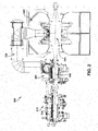
- Turbine 200 can include an HP section 210, an IP section 220, an LP section 240, and a crossover pipe 230.
- Turbine 200 also includes a drum rotor 250 that rotates within sections 210, 220, and 240.
- turbine 200 includes an HP section 210 having a double shell casing, and an IP section 220 having a single shell casing.
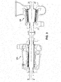
- a close up view showing HP section 210 and IP section 220 is provided in FIG. 3 in order to better illustrate the different casings in the two sections.
- a close up cross-sectional view of HP section 210 is shown in FIG. 4
- a close up cross-sectional view of IP section 220 is shown in FIG. 5 .
- HP section 210 includes a conventional double shell casing, specifically an outer shell 212 and an inner shell 214. As such, there are two walls 212, 214 between drum rotor 250 and the exterior of the turbine. As shown in FIG. 5 , in contrast, IP section 220 has a single shell casing 222. In other words, there is only one wall 222 between drum rotor 250 and the exterior of the turbine.
- HP section 210 and IP section 220 also include a plurality of sets of individual nozzles formed in the shape of a ring, e.g., nozzle ring assemblies 224, positioned such that each nozzle ring assembly 224 surrounds drum rotor 250.
- nozzle ring assemblies 224 can be axially spaced along single shell casing 222, for example, by being positioned in grooves in casings 214, 222, and can comprise similar type material as drum rotor 250.
- Nozzle ring assemblies 224 can be fitted to drum rotor 250 thereby minimizing clearances to improve steam path performance.
- each individual nozzle ring assembly 224 includes a supporting ring 226 for supporting at least one set of corresponding nozzles 228.
- Each set of nozzles 228 can be coupled to supporting ring 226 by a variety of means, for example, nozzles 228 can be slid into grooves in ring 226, or other mechanical means for coupling can be used. While a cross-sectional view is shown in FIG. 6 , it will be understood by one having skill in the art that each set of nozzles 228 comprises individual nozzles circumferentially positioned around drum rotor 250. In FIG.
- nozzle ring assemblies 224 there are four nozzle ring assemblies 224 shown, each including one supporting ring 226, and with each supporting ring 226 supporting two sets of nozzles 228.
- any desired number of supporting rings 226 and nozzles 228 can be used.
- three sets of nozzles 228 can be included in each supporting ring 226.
- connection to condenser 260 can be based on the flow thru the steam turbine and the condenser pressure.
- the connection can comprise a side exhaust connection via a transition duct to the condenser, as shown in FIG. 7 .
- condenser 260 is positioned to the side of LP section 240, rather than above or below LP section 240.
- the connection can comprise a downward connection, as shown in FIG. 8 .
- condenser 260 is positioned vertically below LP section 240 such that the exhaust is expelled downward from LP section 240 to condenser 260.
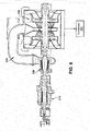
- the connection comprises an axial connection, as shown in FIG. 9 .
- LP section 240 comprises a single-flow LP section and condenser 260 is axially aligned with LP section 240.
- a turbine could be positioned such that LP section 240 could be ducted outside a building into a condenser outside.
- Embodiments of this invention include a steam turbine with an HP section that uses the conventional double shell drum design, and an IP section that uses a single casing drum design.
- the relatively low pressure typical of an IP turbine section allows the use of a single shell configuration.
- the single shell drum construction in the IP section enables high performance while reducing aspects of IP product cost (e.g., material, construction, installation, etc.).
- the additional of the nozzle ring assemblies, with individual alignment of the nozzles to the drum rotor further reduces the radial clearance and improves performance of the turbine.
- the conventional configuration with a two shell casing in both the HP and IP sections, only permits an average alignment of all stages to the rotor, and thereby provides sub-optimal radial clearance.
- the torque generated by the steam turbine can be transmitted to the rest of the power train via a clutch 262 located at the HP end of the turbine, or for multi-shaft applications (i.e., a steam turbine as the only prime mover on the shaft), a solid coupling can be used between the steam turbine and the generator.
Landscapes
- Engineering & Computer Science (AREA)
- Mechanical Engineering (AREA)
- General Engineering & Computer Science (AREA)
- Chemical & Material Sciences (AREA)
- Combustion & Propulsion (AREA)
- Turbine Rotor Nozzle Sealing (AREA)
Abstract
Description
- Embodiments of the invention relate generally to steam turbines and, more particularly, to a steam turbine having an Intermediate Pressure (IP) section with a single shell casing.
- Conventional steam turbines use a wheel and diaphragm or drum rotor construction with a traditional double shell casing. While single shell casings have also been used, such applications have been limited to wheel and diaphragm configurations, not drum rotor configurations. In addition, while individual nozzle ring assemblies have been used with IP sections of steam turbines, those IP sections typically have a traditional double shell casing to support the individual nozzle stages. Conventional steam turbines utilizing wheel and diaphragm construction are limited by the pressure limit of the single casing and the manufacture of the diaphragm being limited to a single stage.
- A steam turbine with a drum rotor utilizing individual nozzle ring assemblies in the IP section incased by a single shell is disclosed herein. In one embodiment, a steam turbine has a high pressure (HP) section with a double shell drum and an intermediate pressure (IP) section with a single shell drum, with the IP section including a plurality of individual nozzle ring assemblies axially spaced along the single shell casing, such that each nozzle ring assembly surrounds the drum rotor. In other embodiments, a low pressure section (LP) of the steam turbine can have a single-flow or dual-flow connection to a condenser, and the condenser can be positioned to the side, vertically below, or axially aligned with the LP section.
- A first aspect of the invention provides a steam turbine including an intermediate pressure (IP) section having a single shell casing, wherein the IP section includes: a drum rotor; and a plurality of nozzle ring assemblies axially spaced along the single shell casing, such that each nozzle ring assembly surrounds the drum rotor, and wherein each nozzle ring assembly includes: a supporting ring; and at least one set of individual nozzles coupled to the supporting ring.
- A second aspect of the invention provides a steam turbine comprising: a high pressure (HP) section having a double shell casing; an intermediate pressure (IP) section fluidly connected to the HP section, wherein the IP section has a single shell casing, and wherein the IP section includes: a drum rotor; and a plurality of nozzle ring assemblies axially spaced along the single shell casing, such that each nozzle ring assembly surrounds the drum rotor, and wherein each nozzle ring assembly includes: a supporting ring; and at least one set of individual nozzles coupled to the supporting ring; and a low pressure (LP) section fluidly connected to the IP section, wherein the LP section is also connected to a condenser.
- Embodiments of the present invention will now be described, by way of example only, with reference to the accompanying drawings in which:
-
FIG. 1 shows a cut-away side perspective view of a conventional steam turbine; -
FIG. 2 shows a cross-sectional schematic of a steam turbine according to an embodiment of this invention; -
FIG. 3 shows a cross-sectional schematic of a high pressure (HP) section and an intermediate pressure (IP) section of a steam turbine according to an embodiment of this invention; -
FIG. 4 shows a cross-sectional schematic of a HP section of a steam turbine according to an embodiment of this invention; -
FIG. 5 shows a cross-sectional schematic of an IP section of a steam turbine according to an embodiment of this invention; -
FIG. 6 shows a cross-sectional schematic of an IP section of a steam turbine showing a plurality of nozzle ring assemblies according to an embodiment of this invention; -
FIG. 7 shows an isometric view of a portion of steam turbine according to an embodiment of this invention including a side exhaust connection to a condenser; -
FIG. 8 shows a cross-sectional view of a steam turbine including a downward exhaust connection to a condenser according to an embodiment of this invention; and -
FIG. 9 shows an isometric view of a steam turbine including an axial exhaust connection to a condenser according to an embodiment of this invention. - It is noted that the drawings are not necessarily to scale. The drawings are intended to depict only typical aspects of the invention, and therefore should not be considered as limiting the scope of the invention. In the drawings, like numbering represents like elements between the drawings.
- A steam turbine having a drum rotor utilizing individual nozzle ring assemblies in the IP section incased by a single shell is disclosed herein. In one embodiment, a steam turbine having a high pressure (HP) section with a double shell drum and an intermediate pressure (IP) section with a single shell drum is disclosed, with the IP section including a plurality of individual nozzle ring assemblies surrounding the drum rotor. In other embodiments, a low pressure section (LP) of the steam turbine can have a single-flow or dual-flow connection to a condenser, and the connection can comprise a side connection, a downward flow connection or an axial connection to the condenser.
- Turning now to the drawings,
FIG. 1 shows a cut-away side perspective view of a conventional doubleflow steam turbine 100. As shown inFIG. 1 ,steam turbine 100 includes a high-pressure (HP)section 110, an intermediate-pressure (IP)section 120, and a low-pressure (LP)section 140. Thesteam turbine 100 shown inFIG. 1 has a dual-flow LP section 140, thereforeLP section 140 includes afirst LP section 142 and asecond LP section 144.Steam turbine 100 further includes acrossover pipe 130 betweenIP section 120 andLP sections feed 132 fromcrossover pipe 130 toLP sections drive train 145 extending through HPsection 110,IP section 120, andLP section 140. -
Steam turbine 100 is referred to as a drum rotor turbine because it includes adrum rotor 150, rotating within each section. Also,steam turbine 100, as shown inFIG. 1 , is configured to connect to a condenser (not shown inFIG. 1 ) through a side exhaust, as will be discussed in more detail herein. As shown inFIG. 1 , HPsection 110 andIP section 120 have conventional double shell casings, specifically, as shown inFIG. 1 , HPsection 110 has adouble casing 112, andIP section 120 has adouble casing 122. In other words,casings drum rotor 150 and the exterior of the turbine. - Turning to
FIG. 2 , a cross-sectional view of asteam turbine 200 according to an embodiment of this invention is shown.Turbine 200 can include an HPsection 210, anIP section 220, anLP section 240, and acrossover pipe 230. Turbine 200 also includes adrum rotor 250 that rotates withinsections conventional steam turbine 100 shown inFIG. 1 ,turbine 200 includes an HPsection 210 having a double shell casing, and anIP section 220 having a single shell casing. A close up view showing HPsection 210 andIP section 220 is provided inFIG. 3 in order to better illustrate the different casings in the two sections. In addition, a close up cross-sectional view of HPsection 210 is shown inFIG. 4 , and a close up cross-sectional view ofIP section 220 is shown inFIG. 5 . - As
FIG. 4 shows, HPsection 210 includes a conventional double shell casing, specifically anouter shell 212 and aninner shell 214. As such, there are twowalls drum rotor 250 and the exterior of the turbine. As shown inFIG. 5 , in contrast,IP section 220 has asingle shell casing 222. In other words, there is only onewall 222 betweendrum rotor 250 and the exterior of the turbine. - As shown most clearly in
FIGS. 4 and5 , HPsection 210 andIP section 220 also include a plurality of sets of individual nozzles formed in the shape of a ring, e.g.,nozzle ring assemblies 224, positioned such that eachnozzle ring assembly 224 surroundsdrum rotor 250. Thesenozzle ring assemblies 224 can be axially spaced alongsingle shell casing 222, for example, by being positioned in grooves incasings drum rotor 250.Nozzle ring assemblies 224 can be fitted todrum rotor 250 thereby minimizing clearances to improve steam path performance. - A close up cross-sectional view of a plurality of
nozzle ring assemblies 224 positioned inIP section 220 is shown inFIG. 6 . As shown inFIG. 6 , each individualnozzle ring assembly 224 includes a supportingring 226 for supporting at least one set ofcorresponding nozzles 228. Each set ofnozzles 228 can be coupled to supportingring 226 by a variety of means, for example,nozzles 228 can be slid into grooves inring 226, or other mechanical means for coupling can be used. While a cross-sectional view is shown inFIG. 6 , it will be understood by one having skill in the art that each set ofnozzles 228 comprises individual nozzles circumferentially positioned arounddrum rotor 250. InFIG. 6 , there are fournozzle ring assemblies 224 shown, each including one supportingring 226, and with each supportingring 226 supporting two sets ofnozzles 228. However, it is understood that any desired number of supportingrings 226 andnozzles 228 can be used. For example, as can be seen inFIG. 4 , three sets ofnozzles 228 can be included in each supportingring 226. - Turning to
FIGS. 7-9 , as will be understood by one having skill in the art, it is desired to connectLP section 240 to acondenser 260. The type of connection tocondenser 260 can be based on the flow thru the steam turbine and the condenser pressure. In one embodiment, the connection can comprise a side exhaust connection via a transition duct to the condenser, as shown inFIG. 7 . In this embodiment,condenser 260 is positioned to the side ofLP section 240, rather than above or belowLP section 240. In another embodiment, the connection can comprise a downward connection, as shown inFIG. 8 . In this embodiment,condenser 260 is positioned vertically belowLP section 240 such that the exhaust is expelled downward fromLP section 240 tocondenser 260. In another embodiment, the connection comprises an axial connection, as shown inFIG. 9 . In the example shown inFIG. 9 ,LP section 240 comprises a single-flow LP section andcondenser 260 is axially aligned withLP section 240. In this example, a turbine could be positioned such thatLP section 240 could be ducted outside a building into a condenser outside. - Embodiments of this invention include a steam turbine with an HP section that uses the conventional double shell drum design, and an IP section that uses a single casing drum design. The relatively low pressure typical of an IP turbine section (relative to the HP section) allows the use of a single shell configuration. The single shell drum construction in the IP section enables high performance while reducing aspects of IP product cost (e.g., material, construction, installation, etc.). The additional of the nozzle ring assemblies, with individual alignment of the nozzles to the drum rotor further reduces the radial clearance and improves performance of the turbine. In contrast, the conventional configuration, with a two shell casing in both the HP and IP sections, only permits an average alignment of all stages to the rotor, and thereby provides sub-optimal radial clearance. As also shown in
FIG. 9 , for single-shaft plants (i.e., a steam turbine on the same shaft with other prime movers), the torque generated by the steam turbine can be transmitted to the rest of the power train via a clutch 262 located at the HP end of the turbine, or for multi-shaft applications (i.e., a steam turbine as the only prime mover on the shaft), a solid coupling can be used between the steam turbine and the generator. - The terminology used herein is for the purpose of describing particular embodiments only and is not intended to be limiting of the disclosure. As used herein, the singular forms "a", "an" and "the" are intended to include the plural forms as well, unless the context clearly indicates otherwise. It will be further understood that the terms "comprises" and/or "comprising," when used in this specification, specify the presence of stated features, integers, steps, operations, elements, and/or components, but do not preclude the presence or addition of one or more other features, integers, steps, operations, elements, components, and/or groups thereof.
- This written description uses examples to disclose the invention, including the best mode, and also to enable any person skilled in the art to practice the invention, including making and using any devices or systems and performing any related or incorporated methods. The patentable scope of the invention is defined by the claims, and may include other examples that occur to those skilled in the art. Such other examples are intended to be within the scope of the claims if they have structural elements that do not differ from the literal language of the claims, or if they include equivalent structural elements with insubstantial differences from the literal language of the claims.
Claims (8)
- A steam turbine (200) comprising:an intermediate pressure (IP) section (220) having a single shell casing (222), wherein the IP section (220) includes:a drum rotor (250); anda plurality of nozzle ring assemblies (224) axially spaced along the single shell casing (222), such that each nozzle ring assembly (224) surrounds the drum rotor (250), and wherein each nozzle ring assembly (224) includes:a supporting ring (226); andat least one set of individual nozzles (228) coupled to the supporting ring (226).
- The steam turbine of claim 1, further comprising a low pressure (LP) section (240) fluidly connected to the IP section (220), wherein the LP section (240) is also connected to a condenser (260).
- The steam turbine of claim 2, wherein the condenser (260) is positioned to the side of the LP section (240), and the condenser (260) is connected to the LP section (240) via a transition duct.
- The steam turbine of claim 2, wherein the condenser (260) is positioned vertically below the LP section (240).
- The steam turbine of claim 2, wherein the condenser (260) is axially aligned with the LP section (240).
- The steam turbine of any preceding claim, further comprising a high pressure (HP) section (210) fluidly connected to the IP section (220), wherein the HP section (210) has a double shell casing (112,122).
- The steam turbine of any preceding claim, wherein each nozzle ring assembly(224) includes two sets of individual nozzles (228).
- The steam turbine of any preceding claim, wherein each nozzle ring assembly (224) is fitted into a groove in the single shell casing (228).
Applications Claiming Priority (1)
| Application Number | Priority Date | Filing Date | Title |
|---|---|---|---|
| US13/362,329 US8926273B2 (en) | 2012-01-31 | 2012-01-31 | Steam turbine with single shell casing, drum rotor, and individual nozzle rings |
Publications (3)
| Publication Number | Publication Date |
|---|---|
| EP2623721A2 true EP2623721A2 (en) | 2013-08-07 |
| EP2623721A3 EP2623721A3 (en) | 2017-07-26 |
| EP2623721B1 EP2623721B1 (en) | 2022-10-19 |
Family
ID=47631311
Family Applications (1)
| Application Number | Title | Priority Date | Filing Date |
|---|---|---|---|
| EP13152583.4A Active EP2623721B1 (en) | 2012-01-31 | 2013-01-24 | Steam turbine with single shell casing, drum rotor, and individual nozzle rings |
Country Status (5)
| Country | Link |
|---|---|
| US (1) | US8926273B2 (en) |
| EP (1) | EP2623721B1 (en) |
| JP (1) | JP6183947B2 (en) |
| CN (1) | CN103225515B (en) |
| RU (1) | RU2013103750A (en) |
Cited By (1)
| Publication number | Priority date | Publication date | Assignee | Title |
|---|---|---|---|---|
| WO2016184678A1 (en) * | 2015-05-15 | 2016-11-24 | General Electric Technology Gmbh | Steam turbine foundation |
Families Citing this family (1)
| Publication number | Priority date | Publication date | Assignee | Title |
|---|---|---|---|---|
| JP6087803B2 (en) * | 2013-12-25 | 2017-03-01 | 三菱重工業株式会社 | Steam turbine |
Family Cites Families (34)
| Publication number | Priority date | Publication date | Assignee | Title |
|---|---|---|---|---|
| US3498062A (en) * | 1966-08-24 | 1970-03-03 | English Electric Co Ltd | Turbine plant |
| JPS5366501U (en) * | 1976-11-08 | 1978-06-05 | ||
| FR2583458B1 (en) * | 1985-06-14 | 1987-08-07 | Alsthom Atlantique | CONNECTION DEVICE BETWEEN A STEAM TURBINE AND A CONDENSER. |
| DE3521664A1 (en) | 1985-06-18 | 1986-12-18 | BBC Aktiengesellschaft Brown, Boveri & Cie., Baden, Aargau | METHOD FOR FASTENING BLADES ON THE CIRCUMFERENCE OF THE ROTOR BODY OF A STEAM TURBINE |
| US4866941A (en) * | 1988-07-05 | 1989-09-19 | Westinghouse Electric Corp. | Single condenser arrangement for side exhaust turbine |
| US5383768A (en) * | 1989-02-03 | 1995-01-24 | Hitachi, Ltd. | Steam turbine, rotor shaft thereof, and heat resisting steel |
| US4961310A (en) | 1989-07-03 | 1990-10-09 | General Electric Company | Single shaft combined cycle turbine |
| FR2690202B1 (en) | 1992-04-17 | 1995-07-07 | Alsthom Gec | IMPROVEMENTS ON HIGH PRESSURE MODULES OF TURBINE ROTOR TURBINE WITH VAPOR INTAKE OF VERY HIGH CHARACTERISTICS. |
| US5411365A (en) * | 1993-12-03 | 1995-05-02 | General Electric Company | High pressure/intermediate pressure section divider for an opposed flow steam turbine |
| JPH11343807A (en) * | 1998-06-01 | 1999-12-14 | Mitsubishi Heavy Ind Ltd | Connecting stator blade for steam turbine |
| CN1119505C (en) * | 1999-10-29 | 2003-08-27 | 三菱重工业株式会社 | Steam turbine with improved outer shell cooling system |
| JP2001193414A (en) * | 2000-01-17 | 2001-07-17 | Mitsubishi Heavy Ind Ltd | Steam turbine |
| JP2001221012A (en) * | 2000-02-10 | 2001-08-17 | Toshiba Corp | Steam turbine and power generation equipment |
| JP4040922B2 (en) * | 2001-07-19 | 2008-01-30 | 株式会社東芝 | Assembly type nozzle diaphragm and its assembly method |
| US6843479B2 (en) | 2002-07-30 | 2005-01-18 | General Electric Company | Sealing of nozzle slashfaces in a steam turbine |
| EP1429219A1 (en) | 2002-12-10 | 2004-06-16 | Abb Research Ltd. | Design of thick-walled components for power plants from crack-growth models |
| GB0319002D0 (en) | 2003-05-13 | 2003-09-17 | Alstom Switzerland Ltd | Improvements in or relating to steam turbines |
| DE10355738A1 (en) | 2003-11-28 | 2005-06-16 | Alstom Technology Ltd | Rotor for a turbine |
| GB0416931D0 (en) * | 2004-07-29 | 2004-09-01 | Alstom Technology Ltd | Axial flow steam turbine assembly |
| GB0416932D0 (en) | 2004-07-29 | 2004-09-01 | Alstom Technology Ltd | Axial flow steam turbine assembly |
| GB0505978D0 (en) | 2005-03-24 | 2005-04-27 | Alstom Technology Ltd | Interlocking turbine blades |
| JP4783053B2 (en) | 2005-04-28 | 2011-09-28 | 株式会社東芝 | Steam turbine power generation equipment |
| EP1744019A1 (en) | 2005-07-14 | 2007-01-17 | Siemens Aktiengesellschaft | Steam turbine, steam turbines arrangement, steam turbine plant and method for operating the steam turbines arrangement |
| US7507073B2 (en) * | 2006-02-24 | 2009-03-24 | General Electric Company | Methods and apparatus for assembling a steam turbine bucket |
| US7713024B2 (en) * | 2007-02-09 | 2010-05-11 | General Electric Company | Bling nozzle/carrier interface design for a steam turbine |
| JP2009030486A (en) * | 2007-07-25 | 2009-02-12 | Mitsubishi Heavy Ind Ltd | Marine steam turbine |
| EP2131013A1 (en) | 2008-04-14 | 2009-12-09 | Siemens Aktiengesellschaft | Steam turbine system for a power plant |
| US20100038917A1 (en) | 2008-08-15 | 2010-02-18 | General Electric Company | Steam turbine clutch and method for disengagement of steam turbine from generator |
| US8167566B2 (en) | 2008-12-31 | 2012-05-01 | General Electric Company | Rotor dovetail hook-to-hook fit |
| US8231338B2 (en) * | 2009-05-05 | 2012-07-31 | General Electric Company | Turbine shell with pin support |
| US20100310356A1 (en) | 2009-06-04 | 2010-12-09 | General Electric Company | Clutched steam turbine low pressure sections and methods therefore |
| EP2305364A1 (en) | 2009-09-29 | 2011-04-06 | Alstom Technology Ltd | Power plant for CO2 capture |
| US8348608B2 (en) | 2009-10-14 | 2013-01-08 | General Electric Company | Turbomachine rotor cooling |
| US8944761B2 (en) * | 2011-01-21 | 2015-02-03 | General Electric Company | Welded rotor, a steam turbine having a welded rotor and a method for producing a welded rotor |
-
2012
- 2012-01-31 US US13/362,329 patent/US8926273B2/en active Active
-
2013
- 2013-01-24 JP JP2013010708A patent/JP6183947B2/en active Active
- 2013-01-24 EP EP13152583.4A patent/EP2623721B1/en active Active
- 2013-01-29 RU RU2013103750/06A patent/RU2013103750A/en unknown
- 2013-01-31 CN CN201310037521.XA patent/CN103225515B/en active Active
Non-Patent Citations (1)
| Title |
|---|
| None |
Cited By (1)
| Publication number | Priority date | Publication date | Assignee | Title |
|---|---|---|---|---|
| WO2016184678A1 (en) * | 2015-05-15 | 2016-11-24 | General Electric Technology Gmbh | Steam turbine foundation |
Also Published As
| Publication number | Publication date |
|---|---|
| EP2623721B1 (en) | 2022-10-19 |
| US20130195644A1 (en) | 2013-08-01 |
| CN103225515A (en) | 2013-07-31 |
| JP6183947B2 (en) | 2017-08-23 |
| US8926273B2 (en) | 2015-01-06 |
| JP2013155734A (en) | 2013-08-15 |
| RU2013103750A (en) | 2014-08-10 |
| CN103225515B (en) | 2016-11-23 |
| EP2623721A3 (en) | 2017-07-26 |
Similar Documents
| Publication | Publication Date | Title |
|---|---|---|
| US9303521B2 (en) | Interstage coverplate assembly for arranging between adjacent rotor stages of a rotor assembly | |
| CN103109044B (en) | Turbine jet engine ventilation duct, the method for this ventilation duct is installed and is provided with the turbine jet engine of this ventilation duct | |
| US9567864B2 (en) | Centrifugal impeller and turbomachine | |
| JP5085987B2 (en) | Method and system for assembling a turbine | |
| EP3189215B1 (en) | A transition-to-turbine seal assembly | |
| JP2011140945A (en) | Steam turbine stationary component seal | |
| JP2018513299A (en) | Multi-stage turbine for preferably an organic Rankine cycle ORC plant | |
| KR102243459B1 (en) | Steam turbine | |
| US9243499B2 (en) | Gas turbine rotor comprising an axially displaceable turbine rotor shaft | |
| US8864461B2 (en) | Turbine for the expansion of gas/vapour | |
| US20150050135A1 (en) | Stator blade diaphragm ring, steam turbine and method | |
| US8926273B2 (en) | Steam turbine with single shell casing, drum rotor, and individual nozzle rings | |
| WO2010000228A3 (en) | Rotor blade and flow engine comprising a rotor blade | |
| US11352912B2 (en) | Steam turbine facility and combined cycle plant | |
| US20170241433A1 (en) | Centrifugal turbomachine with two stages arranged back-to-back and with an annular transfer duct between the stages | |
| US20140037439A1 (en) | Turbomachine exhaust diffuser | |
| EP3056695B1 (en) | Single shaft combined cycle power plant shaft arrangement | |
| JP6249927B2 (en) | Steam turbine | |
| US10982545B2 (en) | Rotor coupling ring | |
| JP2013100784A (en) | Compressor stator and axial flow compressor | |
| US20140363300A1 (en) | Closure bucket for turbo-machine | |
| RU2459119C1 (en) | Flexible joint sealing assembly | |
| CN103790655A (en) | Turbine cowling system |
Legal Events
| Date | Code | Title | Description |
|---|---|---|---|
| PUAI | Public reference made under article 153(3) epc to a published international application that has entered the european phase |
Free format text: ORIGINAL CODE: 0009012 |
|
| AK | Designated contracting states |
Kind code of ref document: A2 Designated state(s): AL AT BE BG CH CY CZ DE DK EE ES FI FR GB GR HR HU IE IS IT LI LT LU LV MC MK MT NL NO PL PT RO RS SE SI SK SM TR |
|
| AX | Request for extension of the european patent |
Extension state: BA ME |
|
| PUAL | Search report despatched |
Free format text: ORIGINAL CODE: 0009013 |
|
| AK | Designated contracting states |
Kind code of ref document: A3 Designated state(s): AL AT BE BG CH CY CZ DE DK EE ES FI FR GB GR HR HU IE IS IT LI LT LU LV MC MK MT NL NO PL PT RO RS SE SI SK SM TR |
|
| AX | Request for extension of the european patent |
Extension state: BA ME |
|
| RIC1 | Information provided on ipc code assigned before grant |
Ipc: F01D 9/04 20060101AFI20170620BHEP Ipc: F01D 25/26 20060101ALI20170620BHEP Ipc: F01D 25/24 20060101ALI20170620BHEP |
|
| STAA | Information on the status of an ep patent application or granted ep patent |
Free format text: STATUS: REQUEST FOR EXAMINATION WAS MADE |
|
| 17P | Request for examination filed |
Effective date: 20180126 |
|
| RBV | Designated contracting states (corrected) |
Designated state(s): AL AT BE BG CH CY CZ DE DK EE ES FI FR GB GR HR HU IE IS IT LI LT LU LV MC MK MT NL NO PL PT RO RS SE SI SK SM TR |
|
| STAA | Information on the status of an ep patent application or granted ep patent |
Free format text: STATUS: EXAMINATION IS IN PROGRESS |
|
| 17Q | First examination report despatched |
Effective date: 20200403 |
|
| GRAP | Despatch of communication of intention to grant a patent |
Free format text: ORIGINAL CODE: EPIDOSNIGR1 |
|
| STAA | Information on the status of an ep patent application or granted ep patent |
Free format text: STATUS: GRANT OF PATENT IS INTENDED |
|
| INTG | Intention to grant announced |
Effective date: 20220801 |
|
| GRAS | Grant fee paid |
Free format text: ORIGINAL CODE: EPIDOSNIGR3 |
|
| GRAA | (expected) grant |
Free format text: ORIGINAL CODE: 0009210 |
|
| STAA | Information on the status of an ep patent application or granted ep patent |
Free format text: STATUS: THE PATENT HAS BEEN GRANTED |
|
| AK | Designated contracting states |
Kind code of ref document: B1 Designated state(s): AL AT BE BG CH CY CZ DE DK EE ES FI FR GB GR HR HU IE IS IT LI LT LU LV MC MK MT NL NO PL PT RO RS SE SI SK SM TR |
|
| REG | Reference to a national code |
Ref country code: GB Ref legal event code: FG4D |
|
| REG | Reference to a national code |
Ref country code: CH Ref legal event code: EP |
|
| REG | Reference to a national code |
Ref country code: DE Ref legal event code: R096 Ref document number: 602013082695 Country of ref document: DE |
|
| REG | Reference to a national code |
Ref country code: IE Ref legal event code: FG4D |
|
| REG | Reference to a national code |
Ref country code: AT Ref legal event code: REF Ref document number: 1525665 Country of ref document: AT Kind code of ref document: T Effective date: 20221115 |
|
| REG | Reference to a national code |
Ref country code: LT Ref legal event code: MG9D |
|
| REG | Reference to a national code |
Ref country code: NL Ref legal event code: MP Effective date: 20221019 |
|
| REG | Reference to a national code |
Ref country code: AT Ref legal event code: MK05 Ref document number: 1525665 Country of ref document: AT Kind code of ref document: T Effective date: 20221019 |
|
| PG25 | Lapsed in a contracting state [announced via postgrant information from national office to epo] |
Ref country code: NL Free format text: LAPSE BECAUSE OF FAILURE TO SUBMIT A TRANSLATION OF THE DESCRIPTION OR TO PAY THE FEE WITHIN THE PRESCRIBED TIME-LIMIT Effective date: 20221019 |
|
| PG25 | Lapsed in a contracting state [announced via postgrant information from national office to epo] |
Ref country code: SE Free format text: LAPSE BECAUSE OF FAILURE TO SUBMIT A TRANSLATION OF THE DESCRIPTION OR TO PAY THE FEE WITHIN THE PRESCRIBED TIME-LIMIT Effective date: 20221019 Ref country code: PT Free format text: LAPSE BECAUSE OF FAILURE TO SUBMIT A TRANSLATION OF THE DESCRIPTION OR TO PAY THE FEE WITHIN THE PRESCRIBED TIME-LIMIT Effective date: 20230220 Ref country code: NO Free format text: LAPSE BECAUSE OF FAILURE TO SUBMIT A TRANSLATION OF THE DESCRIPTION OR TO PAY THE FEE WITHIN THE PRESCRIBED TIME-LIMIT Effective date: 20230119 Ref country code: LT Free format text: LAPSE BECAUSE OF FAILURE TO SUBMIT A TRANSLATION OF THE DESCRIPTION OR TO PAY THE FEE WITHIN THE PRESCRIBED TIME-LIMIT Effective date: 20221019 Ref country code: FI Free format text: LAPSE BECAUSE OF FAILURE TO SUBMIT A TRANSLATION OF THE DESCRIPTION OR TO PAY THE FEE WITHIN THE PRESCRIBED TIME-LIMIT Effective date: 20221019 Ref country code: ES Free format text: LAPSE BECAUSE OF FAILURE TO SUBMIT A TRANSLATION OF THE DESCRIPTION OR TO PAY THE FEE WITHIN THE PRESCRIBED TIME-LIMIT Effective date: 20221019 Ref country code: AT Free format text: LAPSE BECAUSE OF FAILURE TO SUBMIT A TRANSLATION OF THE DESCRIPTION OR TO PAY THE FEE WITHIN THE PRESCRIBED TIME-LIMIT Effective date: 20221019 |
|
| PG25 | Lapsed in a contracting state [announced via postgrant information from national office to epo] |
Ref country code: RS Free format text: LAPSE BECAUSE OF FAILURE TO SUBMIT A TRANSLATION OF THE DESCRIPTION OR TO PAY THE FEE WITHIN THE PRESCRIBED TIME-LIMIT Effective date: 20221019 Ref country code: PL Free format text: LAPSE BECAUSE OF FAILURE TO SUBMIT A TRANSLATION OF THE DESCRIPTION OR TO PAY THE FEE WITHIN THE PRESCRIBED TIME-LIMIT Effective date: 20221019 Ref country code: LV Free format text: LAPSE BECAUSE OF FAILURE TO SUBMIT A TRANSLATION OF THE DESCRIPTION OR TO PAY THE FEE WITHIN THE PRESCRIBED TIME-LIMIT Effective date: 20221019 Ref country code: IS Free format text: LAPSE BECAUSE OF FAILURE TO SUBMIT A TRANSLATION OF THE DESCRIPTION OR TO PAY THE FEE WITHIN THE PRESCRIBED TIME-LIMIT Effective date: 20230219 Ref country code: HR Free format text: LAPSE BECAUSE OF FAILURE TO SUBMIT A TRANSLATION OF THE DESCRIPTION OR TO PAY THE FEE WITHIN THE PRESCRIBED TIME-LIMIT Effective date: 20221019 Ref country code: GR Free format text: LAPSE BECAUSE OF FAILURE TO SUBMIT A TRANSLATION OF THE DESCRIPTION OR TO PAY THE FEE WITHIN THE PRESCRIBED TIME-LIMIT Effective date: 20230120 |
|
| P01 | Opt-out of the competence of the unified patent court (upc) registered |
Effective date: 20230522 |
|
| REG | Reference to a national code |
Ref country code: DE Ref legal event code: R097 Ref document number: 602013082695 Country of ref document: DE |
|
| PG25 | Lapsed in a contracting state [announced via postgrant information from national office to epo] |
Ref country code: SM Free format text: LAPSE BECAUSE OF FAILURE TO SUBMIT A TRANSLATION OF THE DESCRIPTION OR TO PAY THE FEE WITHIN THE PRESCRIBED TIME-LIMIT Effective date: 20221019 Ref country code: RO Free format text: LAPSE BECAUSE OF FAILURE TO SUBMIT A TRANSLATION OF THE DESCRIPTION OR TO PAY THE FEE WITHIN THE PRESCRIBED TIME-LIMIT Effective date: 20221019 Ref country code: EE Free format text: LAPSE BECAUSE OF FAILURE TO SUBMIT A TRANSLATION OF THE DESCRIPTION OR TO PAY THE FEE WITHIN THE PRESCRIBED TIME-LIMIT Effective date: 20221019 Ref country code: DK Free format text: LAPSE BECAUSE OF FAILURE TO SUBMIT A TRANSLATION OF THE DESCRIPTION OR TO PAY THE FEE WITHIN THE PRESCRIBED TIME-LIMIT Effective date: 20221019 Ref country code: CZ Free format text: LAPSE BECAUSE OF FAILURE TO SUBMIT A TRANSLATION OF THE DESCRIPTION OR TO PAY THE FEE WITHIN THE PRESCRIBED TIME-LIMIT Effective date: 20221019 |
|
| PLBE | No opposition filed within time limit |
Free format text: ORIGINAL CODE: 0009261 |
|
| STAA | Information on the status of an ep patent application or granted ep patent |
Free format text: STATUS: NO OPPOSITION FILED WITHIN TIME LIMIT |
|
| PG25 | Lapsed in a contracting state [announced via postgrant information from national office to epo] |
Ref country code: SK Free format text: LAPSE BECAUSE OF FAILURE TO SUBMIT A TRANSLATION OF THE DESCRIPTION OR TO PAY THE FEE WITHIN THE PRESCRIBED TIME-LIMIT Effective date: 20221019 Ref country code: AL Free format text: LAPSE BECAUSE OF FAILURE TO SUBMIT A TRANSLATION OF THE DESCRIPTION OR TO PAY THE FEE WITHIN THE PRESCRIBED TIME-LIMIT Effective date: 20221019 |
|
| REG | Reference to a national code |
Ref country code: CH Ref legal event code: PL |
|
| 26N | No opposition filed |
Effective date: 20230720 |
|
| GBPC | Gb: european patent ceased through non-payment of renewal fee |
Effective date: 20230124 |
|
| PG25 | Lapsed in a contracting state [announced via postgrant information from national office to epo] |
Ref country code: LU Free format text: LAPSE BECAUSE OF NON-PAYMENT OF DUE FEES Effective date: 20230124 |
|
| REG | Reference to a national code |
Ref country code: BE Ref legal event code: MM Effective date: 20230131 |
|
| PG25 | Lapsed in a contracting state [announced via postgrant information from national office to epo] |
Ref country code: LI Free format text: LAPSE BECAUSE OF NON-PAYMENT OF DUE FEES Effective date: 20230131 Ref country code: GB Free format text: LAPSE BECAUSE OF NON-PAYMENT OF DUE FEES Effective date: 20230124 Ref country code: CH Free format text: LAPSE BECAUSE OF NON-PAYMENT OF DUE FEES Effective date: 20230131 |
|
| REG | Reference to a national code |
Ref country code: DE Ref legal event code: R081 Ref document number: 602013082695 Country of ref document: DE Owner name: GENERAL ELECTRIC TECHNOLOGY GMBH, CH Free format text: FORMER OWNER: GENERAL ELECTRIC COMPANY, SCHENECTADY, NY, US |
|
| PG25 | Lapsed in a contracting state [announced via postgrant information from national office to epo] |
Ref country code: SI Free format text: LAPSE BECAUSE OF FAILURE TO SUBMIT A TRANSLATION OF THE DESCRIPTION OR TO PAY THE FEE WITHIN THE PRESCRIBED TIME-LIMIT Effective date: 20221019 Ref country code: BE Free format text: LAPSE BECAUSE OF NON-PAYMENT OF DUE FEES Effective date: 20230131 |
|
| PG25 | Lapsed in a contracting state [announced via postgrant information from national office to epo] |
Ref country code: IE Free format text: LAPSE BECAUSE OF NON-PAYMENT OF DUE FEES Effective date: 20230124 |
|
| PG25 | Lapsed in a contracting state [announced via postgrant information from national office to epo] |
Ref country code: MC Free format text: LAPSE BECAUSE OF FAILURE TO SUBMIT A TRANSLATION OF THE DESCRIPTION OR TO PAY THE FEE WITHIN THE PRESCRIBED TIME-LIMIT Effective date: 20221019 |
|
| PG25 | Lapsed in a contracting state [announced via postgrant information from national office to epo] |
Ref country code: MC Free format text: LAPSE BECAUSE OF FAILURE TO SUBMIT A TRANSLATION OF THE DESCRIPTION OR TO PAY THE FEE WITHIN THE PRESCRIBED TIME-LIMIT Effective date: 20221019 |
|
| PG25 | Lapsed in a contracting state [announced via postgrant information from national office to epo] |
Ref country code: BG Free format text: LAPSE BECAUSE OF FAILURE TO SUBMIT A TRANSLATION OF THE DESCRIPTION OR TO PAY THE FEE WITHIN THE PRESCRIBED TIME-LIMIT Effective date: 20221019 |
|
| PG25 | Lapsed in a contracting state [announced via postgrant information from national office to epo] |
Ref country code: BG Free format text: LAPSE BECAUSE OF FAILURE TO SUBMIT A TRANSLATION OF THE DESCRIPTION OR TO PAY THE FEE WITHIN THE PRESCRIBED TIME-LIMIT Effective date: 20221019 |
|
| PG25 | Lapsed in a contracting state [announced via postgrant information from national office to epo] |
Ref country code: CY Free format text: LAPSE BECAUSE OF FAILURE TO SUBMIT A TRANSLATION OF THE DESCRIPTION OR TO PAY THE FEE WITHIN THE PRESCRIBED TIME-LIMIT; INVALID AB INITIO Effective date: 20130124 |
|
| PG25 | Lapsed in a contracting state [announced via postgrant information from national office to epo] |
Ref country code: HU Free format text: LAPSE BECAUSE OF FAILURE TO SUBMIT A TRANSLATION OF THE DESCRIPTION OR TO PAY THE FEE WITHIN THE PRESCRIBED TIME-LIMIT; INVALID AB INITIO Effective date: 20130124 |
|
| PG25 | Lapsed in a contracting state [announced via postgrant information from national office to epo] |
Ref country code: TR Free format text: LAPSE BECAUSE OF FAILURE TO SUBMIT A TRANSLATION OF THE DESCRIPTION OR TO PAY THE FEE WITHIN THE PRESCRIBED TIME-LIMIT Effective date: 20221019 |
|
| PGFP | Annual fee paid to national office [announced via postgrant information from national office to epo] |
Ref country code: FR Payment date: 20251217 Year of fee payment: 14 |
|
| PGFP | Annual fee paid to national office [announced via postgrant information from national office to epo] |
Ref country code: DE Payment date: 20251217 Year of fee payment: 14 |
|
| PGFP | Annual fee paid to national office [announced via postgrant information from national office to epo] |
Ref country code: IT Payment date: 20260107 Year of fee payment: 14 |