EP2623714A2 - Turbine cooling system - Google Patents
Turbine cooling system Download PDFInfo
- Publication number
- EP2623714A2 EP2623714A2 EP12198418.1A EP12198418A EP2623714A2 EP 2623714 A2 EP2623714 A2 EP 2623714A2 EP 12198418 A EP12198418 A EP 12198418A EP 2623714 A2 EP2623714 A2 EP 2623714A2
- Authority
- EP
- European Patent Office
- Prior art keywords
- turbine
- cooling air
- rotor wheel
- wheel space
- turbine rotor
- Prior art date
- Legal status (The legal status is an assumption and is not a legal conclusion. Google has not performed a legal analysis and makes no representation as to the accuracy of the status listed.)
- Withdrawn
Links
- 238000001816 cooling Methods 0.000 title claims abstract description 103
- 239000012530 fluid Substances 0.000 claims abstract description 8
- 238000012856 packing Methods 0.000 claims abstract description 6
- 239000002184 metal Substances 0.000 claims description 6
- 239000007789 gas Substances 0.000 description 9
- 239000000446 fuel Substances 0.000 description 8
- 238000010248 power generation Methods 0.000 description 8
- 238000013459 approach Methods 0.000 description 7
- 238000002485 combustion reaction Methods 0.000 description 7
- 230000007423 decrease Effects 0.000 description 5
- 230000007774 longterm Effects 0.000 description 2
- 239000000203 mixture Substances 0.000 description 2
- 230000004075 alteration Effects 0.000 description 1
- 230000005465 channeling Effects 0.000 description 1
- 238000010586 diagram Methods 0.000 description 1
- 238000000605 extraction Methods 0.000 description 1
- 230000003134 recirculating effect Effects 0.000 description 1
- 238000000926 separation method Methods 0.000 description 1
- 238000006467 substitution reaction Methods 0.000 description 1
Images

Classifications
-
- F—MECHANICAL ENGINEERING; LIGHTING; HEATING; WEAPONS; BLASTING
- F01—MACHINES OR ENGINES IN GENERAL; ENGINE PLANTS IN GENERAL; STEAM ENGINES
- F01D—NON-POSITIVE DISPLACEMENT MACHINES OR ENGINES, e.g. STEAM TURBINES
- F01D25/00—Component parts, details, or accessories, not provided for in, or of interest apart from, other groups
- F01D25/08—Cooling; Heating; Heat-insulation
- F01D25/12—Cooling
-
- F—MECHANICAL ENGINEERING; LIGHTING; HEATING; WEAPONS; BLASTING
- F01—MACHINES OR ENGINES IN GENERAL; ENGINE PLANTS IN GENERAL; STEAM ENGINES
- F01D—NON-POSITIVE DISPLACEMENT MACHINES OR ENGINES, e.g. STEAM TURBINES
- F01D11/00—Preventing or minimising internal leakage of working-fluid, e.g. between stages
- F01D11/001—Preventing or minimising internal leakage of working-fluid, e.g. between stages for sealing space between stator blade and rotor
-
- F—MECHANICAL ENGINEERING; LIGHTING; HEATING; WEAPONS; BLASTING
- F01—MACHINES OR ENGINES IN GENERAL; ENGINE PLANTS IN GENERAL; STEAM ENGINES
- F01D—NON-POSITIVE DISPLACEMENT MACHINES OR ENGINES, e.g. STEAM TURBINES
- F01D25/00—Component parts, details, or accessories, not provided for in, or of interest apart from, other groups
- F01D25/08—Cooling; Heating; Heat-insulation
-
- F—MECHANICAL ENGINEERING; LIGHTING; HEATING; WEAPONS; BLASTING
- F01—MACHINES OR ENGINES IN GENERAL; ENGINE PLANTS IN GENERAL; STEAM ENGINES
- F01D—NON-POSITIVE DISPLACEMENT MACHINES OR ENGINES, e.g. STEAM TURBINES
- F01D5/00—Blades; Blade-carrying members; Heating, heat-insulating, cooling or antivibration means on the blades or the members
- F01D5/02—Blade-carrying members, e.g. rotors
- F01D5/08—Heating, heat-insulating or cooling means
- F01D5/081—Cooling fluid being directed on the side of the rotor disc or at the roots of the blades
-
- F—MECHANICAL ENGINEERING; LIGHTING; HEATING; WEAPONS; BLASTING
- F01—MACHINES OR ENGINES IN GENERAL; ENGINE PLANTS IN GENERAL; STEAM ENGINES
- F01D—NON-POSITIVE DISPLACEMENT MACHINES OR ENGINES, e.g. STEAM TURBINES
- F01D5/00—Blades; Blade-carrying members; Heating, heat-insulating, cooling or antivibration means on the blades or the members
- F01D5/02—Blade-carrying members, e.g. rotors
- F01D5/08—Heating, heat-insulating or cooling means
- F01D5/081—Cooling fluid being directed on the side of the rotor disc or at the roots of the blades
- F01D5/082—Cooling fluid being directed on the side of the rotor disc or at the roots of the blades on the side of the rotor disc
-
- F—MECHANICAL ENGINEERING; LIGHTING; HEATING; WEAPONS; BLASTING
- F01—MACHINES OR ENGINES IN GENERAL; ENGINE PLANTS IN GENERAL; STEAM ENGINES
- F01D—NON-POSITIVE DISPLACEMENT MACHINES OR ENGINES, e.g. STEAM TURBINES
- F01D5/00—Blades; Blade-carrying members; Heating, heat-insulating, cooling or antivibration means on the blades or the members
- F01D5/02—Blade-carrying members, e.g. rotors
- F01D5/08—Heating, heat-insulating or cooling means
- F01D5/085—Heating, heat-insulating or cooling means cooling fluid circulating inside the rotor
- F01D5/087—Heating, heat-insulating or cooling means cooling fluid circulating inside the rotor in the radial passages of the rotor disc
Definitions
- the subject matter disclosed herein relates to a turbine cooling system system, and more specifically to a turbine cooling system having a metering device for modulating cooling air to a forward turbine rotor wheel space.
- Gas turbines generally include a compressor, a combustor, one or more fuel nozzles, and a turbine. Air enters the gas turbine through an air intake and is pressurized by the compressor. The pressurized air is then mixed with fuel supplied by the fuel nozzles. The air-fuel mixture is supplied to the combustors at a specified ratio for combustion. The combustion generates pressurized exhaust gases, which drive blades of the turbine.
- the turbine includes a rotor assembly having a plurality of turbine blades installed on a rotating disk.
- the turbine blades, the rotating disk, and other components in the turbine are subjected to elevated temperatures.
- cooling air is introduced.
- cooling air may be supplied from the combustor plenum and is used to cool a forward turbine rotor wheel space.
- the forward turbine rotor wheel space is located between a nozzle assembly and a compressor exit diffuser of the turbine, and may be subjected to some of the highest temperatures experienced by the turbine. Cooling air is supplied to the forward turbine rotor wheel space in order to operate in a temperature range, which is suitable for long term component durability. Under certain operating conditions, such as high ambient temperatures, the volume of cooling air may be insufficient to maintain the forward turbine rotor wheel space within the desired temperature range for long term component durability.
- the amount of cooling air supplied to the forward turbine rotor wheel space is increased by removing bore plugs from a compressor discharge casing. Removal of the bore plugs results in a portion of the high pressure air exiting the compressor to be diverted to the forward turbine rotor wheel space.
- this approach allows for cooling air to enter the forward turbine rotor wheel space at all operating conditions with no flow control. Therefore, removing the bore plugs results in a reduction in overall performance of the turbine, as more cooling air is supplied than needed during less demanding operating conditions.
- this approach also requires the gas turbine to be shut down and the combustion system removed for access to the bore plugs, which can be troublesome and inconvenient.
- an orifice may be provided to bypass some of the cooling air to the forward turbine rotor wheel space.
- the orifice is typically sized to provide adequate cooling to the forward turbine rotor wheel space during worst case conditions. Therefore, the orifice also results in a reduction in overall performance of the turbine, as more cooling air is supplied than needed during less demanding operating conditions.
- a turbine cooling system having a compressor for supplying cooling air, a forward turbine rotor wheel space, a high-pressure packing seal (HPPS) bypass cavity, and a metering device.
- the forward turbine rotor wheel space is cooled by the cooling air supplied by the compressor.
- the HPPS bypass cavity is in fluid communication with and receives a portion of the cooling air from the compressor, and is in fluid communication with and supplies the cooling air to the forward turbine rotor wheel space.
- the metering device is in operable communication with the forward turbine rotor wheel space and the HPPS bypass cavity to modulate the cooling air supplied to the forward turbine rotor wheel space from the HPPS bypass cavity. The metering device modulates the cooling air based on at least one operating condition of the turbine.
- module and sub-module refer to an application specific integrated circuit (ASIC), an electronic circuit, a processor (shared, dedicated, or group) and memory that executes one or more software or firmware programs, a combinational logic circuit, and/or other suitable components that provide the described functionality.
- ASIC application specific integrated circuit
- processor shared, dedicated, or group
- memory that executes one or more software or firmware programs
- combinational logic circuit and/or other suitable components that provide the described functionality.
- FIG. 1 illustrates a schematic diagram of an exemplary power generation system indicated by reference number 10.
- the power generation system 10 is a gas turbine system having a compressor 20, a combustor 22, and a turbine 24. Air enters the power generation system 10 though an air intake 30 located in the compressor 20, and is compressed by the compressor 20. The compressed air is then mixed with fuel by a fuel nozzle 34 located in an end cover (not shown) of the combustor 22. The fuel nozzle 34 injects an air-fuel mixture into the combustor 22 in a specific ratio for combustion. The combustion generates hot pressurized exhaust gases that drives blades (not shown) that are located within the turbine 24.
- the turbine 24 is configured into three stages having six rows of airfoils (not shown) disposed axially for channeling the hot pressurized exhaust gases.
- the turbine 24 includes a first stage stator vane (not shown) that defines a nozzle assembly (not shown).
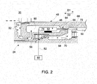
- FIG. 2 is an enlarged view of a portion of the compressor 20 and the turbine 24 illustrating one exemplary embodiment of a metering device 46.
- High pressure compressor discharge air or cooling air is supplied from the compressor 20, and is located within and flows through a plenum 48.
- a forward turbine rotor wheel space 50 is located between the nozzle assembly (not shown) and a compressor exit diffuser (not shown).
- the temperature of the cooling air in the plenum 48 is lower than the temperature of the air located in the forward turbine rotor wheel space 50.
- the forward turbine rotor wheel space 50 tends to experience some of the highest temperatures of the turbine 24 due to the specific location of the forward turbine rotor wheel space 50 in relation to some of the other components of the power generation system 10, such as the combustor 22. Therefore, the cooling air located in the plenum 48 is used to provide cooling to the forward turbine rotor wheel space 50.
- the metering device 46 is used to modulate the amount of cooling air supplied to the forward turbine rotor wheel space 50.
- the cooling air from the plenum 48 flows through a cooling channel 52.
- a portion of the cooling air from the cooling channel 52 leaks past a pressure packing seal (HPPS) 56 to create a HPPS leakage flow 58.
- HPPS leakage flow 58 flows to the forward turbine rotor wheel space 50, and is employed to provide cooling to the forward turbine rotor wheel space 50.
- the remaining cooling air that does not leak past the HPPS 56 flows into a HPPS bypass cavity 60.
- the metering device 46 is employed to modulate the amount of cooling air supplied to the forward turbine rotor wheel space 50 from the HPPS bypass cavity 60.
- the metering device 46 is typically any type of variable orifice that is able to modulate the amount of cooling air that is supplied to the forward turbine rotor wheel space such as, for example, a valve or a solenoid.
- the metering device 46 is a pintle-type valve 62, however it is understood that other metering devices may be used as well.
- the valve 62 includes a needle or pintle 64 that is an elongated member that cooperates with an orifice 66 located in a wall 68 of the HPPS bypass cavity 60 to modulate the amount of cooling air supplied to the forward turbine rotor wheel space 50.
- the pintle 62 includes an angular outer surface 70, and the orifice 66 also includes a corresponding angular surface 72.
- the pintle 62 is selectively actuated by a valve portion 74 of the pintle-type valve 62 in the directions D1 and D2.
- the valve portion 74 is a piezoelectric device that actuates the pintle 62 based on electrical current, however it is understood that other approaches may be used as well.
- the angular outer surface 70 of the pintle 62 cooperates with the corresponding angular surface 72 of the orifice 66 to modulate the amount of cooling air supplied to the forward turbine rotor wheel space 50. That is, when the pintle 62 is actuated in the first direction D1, the pintle 62 is actuated towards the orifice 66, and decreases the amount of cooling air supplied to the forward turbine rotor wheel space 50. When the pintle 62 is actuated in the second direction D2, the pintle 62 is actuated away from the orifice 66 and the amount of cooling air supplied to the forward turbine rotor wheel space 50 increases.
- the modulation of the metering device 46 is controlled by a control module 80 that is in communication with the metering device 46 through a data link 82.
- the data link 82 could be a hard-wired or a wireless radio frequency (RF) data link used to communicate control signals to the metering device 46.
- the control module 80 includes control logic for sending a control signal to the metering device 46 to either increase or decrease the amount of cooling air supplied to the forward turbine rotor wheel space 50 based on specific operating conditions.
- the control module 80 includes control logic for sending a control signal to the metering device 46 to actuate the pintle 62 in the directions D1 and D2.
- control module 80 either increases or decreases the amount of cooling air based on at least one of the following operating conditions which include but are not limited to ambient temperature, overall back flow margin of the turbine 24, bulk metal temperature of the turbine blades, forward turbine rotor wheel space temperature, turbine emissions requirements, and compressor discharge pressure.
- control module 80 is connected to and receives temperature data from an ambient sensor (not shown). As the ambient temperature changes, the control module 80 includes control logic for sending a control signal to the metering device 46 to either increase or decrease the amount of cooling air to the forward turbine rotor wheel space 50. For example, as the ambient temperature increases, the control module 80 includes control logic for sending a control signal to the metering device 46 to increase the amount of cooling air supplied to the forward turbine rotor wheel space 50.
- the control module 80 may also include control logic for modulating the amount of cooling air supplied to the forward turbine rotor wheel space 50 based on the overall back flow margin of the turbine 24.
- the overall back flow margin is the difference between the cooling air pressure and the gas flow pressure of the turbine 24, where a positive overall back flow margin is typically maintained.
- the back flow margin may be a calculated or measured value.
- the control module 80 includes control logic for sending a control signal to the metering device 46 to increase the amount of cooling air supplied to the forward turbine rotor wheel space 50.
- the control module 80 may include control logic for modulating the cooling air to the forward turbine rotor wheel space 50 based on the bulk metal temperature of the turbine blades (not shown). Specifically, in one embodiment if the bulk metal temperature of the turbine blades exceeds a pre-defined temperature limit, then the control module 80 includes control logic for sending a control signal to the metering device 46 to increase the amount of cooling air supplied to the forward turbine rotor wheel space 50.
- the control module 80 may include control logic for modulating the cooling air to the forward turbine rotor wheel space 50 based on the air temperature of the forward turbine rotor wheel space 50. For example, in one embodiment, if the temperature of the forward turbine rotor wheel space 50 exceeds a pre-defined temperature limit, then the control module 80 includes control logic for increasing the amount of cooling air to the forward turbine rotor wheel space 50.
- the control module 80 may also include control logic for modulating the amount of cooling air to the forward turbine rotor wheel space 50 based on emissions requirements. For example, in one embodiment, during a turndown mode of the power generation system 10, increased airflow extraction out the plenum 48 is utilized to by-pass the primary combustion zone during load rejection resulting in a reduction in the mass flow rate of air entering the combustor 22 (shown in FIG. 1 ); which in turn results in a lower combustion temperature resulting in reduced emissions. Thus the metering device 46 is modulated to increase the amount of cooling air supplied to the forward turbine rotor wheel space 50.
- the control module 80 may also include control logic for modulating the amount of cooling air to the forward turbine rotor wheel space 50 to provide compressor surge protection.
- control logic for modulating the amount of cooling air to the forward turbine rotor wheel space 50 to provide compressor surge protection.
- the pressure ratio of the compressor 20 may eventually exceed a critical value, which results in a rapid reduction of compressor discharge pressure.
- the decrease in compressor discharge pressure results in flow separation, which is known as compressor surge.
- the amount of cooling air to the forward turbine rotor wheel space 50 is modulated to provide a compressor discharge ratio that is a specified margin away from a surge boundary of the compressor 20.
- Modulating the amount of cooling air supplied to the forward turbine rotor wheel space 50 reduces or substantially reduces or eliminates the need to recirculate a portion of the compressor discharge air back to the compressor inlet by an inlet bleed valve. Recirculating a portion of the compressor discharge air back to the compressor inlet is referred to as inlet bleed heat.
- the amount of cooling air is modulated to the forward turbine rotor wheel space 50 in an effort to manage turbine rotor cooling and enhance the part-life of the internal turbine components. Actively modulating the amount of cooling air to the forward turbine rotor wheel space 50 also increases the overall performance of the power generation system 10 when compared to some of the other approaches that are currently being used to increase cooling air to the forward turbine rotor wheel space 50. For example, one approach for increasing cooling air involves removing the bore plugs from the compressor discharge casing. However, this results in cooling air entering the forward turbine rotor wheel space at all operating conditions with no flow control, and reduces the overall performance of the turbine. In contrast, actively modulating the amount of cooling air to the forward turbine rotor wheel space 50 allows for the amount of cooling air to be adjusted depending on specific operating conditions, which in turn increases overall performance of the power generation system 10.
Landscapes
- Engineering & Computer Science (AREA)
- Mechanical Engineering (AREA)
- General Engineering & Computer Science (AREA)
- Turbine Rotor Nozzle Sealing (AREA)
- Control Of Turbines (AREA)
Abstract
Description
- The subject matter disclosed herein relates to a turbine cooling system system, and more specifically to a turbine cooling system having a metering device for modulating cooling air to a forward turbine rotor wheel space.
- Gas turbines generally include a compressor, a combustor, one or more fuel nozzles, and a turbine. Air enters the gas turbine through an air intake and is pressurized by the compressor. The pressurized air is then mixed with fuel supplied by the fuel nozzles. The air-fuel mixture is supplied to the combustors at a specified ratio for combustion. The combustion generates pressurized exhaust gases, which drive blades of the turbine.
- The turbine includes a rotor assembly having a plurality of turbine blades installed on a rotating disk. During operation the turbine blades, the rotating disk, and other components in the turbine are subjected to elevated temperatures. In an effort to maintain the temperature of the internal components of the turbine at acceptable levels, cooling air is introduced. For example, cooling air may be supplied from the combustor plenum and is used to cool a forward turbine rotor wheel space. The forward turbine rotor wheel space is located between a nozzle assembly and a compressor exit diffuser of the turbine, and may be subjected to some of the highest temperatures experienced by the turbine. Cooling air is supplied to the forward turbine rotor wheel space in order to operate in a temperature range, which is suitable for long term component durability. Under certain operating conditions, such as high ambient temperatures, the volume of cooling air may be insufficient to maintain the forward turbine rotor wheel space within the desired temperature range for long term component durability.
- In one approach, the amount of cooling air supplied to the forward turbine rotor wheel space is increased by removing bore plugs from a compressor discharge casing. Removal of the bore plugs results in a portion of the high pressure air exiting the compressor to be diverted to the forward turbine rotor wheel space. However, this approach allows for cooling air to enter the forward turbine rotor wheel space at all operating conditions with no flow control. Therefore, removing the bore plugs results in a reduction in overall performance of the turbine, as more cooling air is supplied than needed during less demanding operating conditions. Moreover, this approach also requires the gas turbine to be shut down and the combustion system removed for access to the bore plugs, which can be troublesome and inconvenient. In another approach, an orifice may be provided to bypass some of the cooling air to the forward turbine rotor wheel space. However, the orifice is typically sized to provide adequate cooling to the forward turbine rotor wheel space during worst case conditions. Therefore, the orifice also results in a reduction in overall performance of the turbine, as more cooling air is supplied than needed during less demanding operating conditions.
- According to one aspect of the invention, a turbine cooling system is provided having a compressor for supplying cooling air, a forward turbine rotor wheel space, a high-pressure packing seal (HPPS) bypass cavity, and a metering device. The forward turbine rotor wheel space is cooled by the cooling air supplied by the compressor. The HPPS bypass cavity is in fluid communication with and receives a portion of the cooling air from the compressor, and is in fluid communication with and supplies the cooling air to the forward turbine rotor wheel space. The metering device is in operable communication with the forward turbine rotor wheel space and the HPPS bypass cavity to modulate the cooling air supplied to the forward turbine rotor wheel space from the HPPS bypass cavity. The metering device modulates the cooling air based on at least one operating condition of the turbine.
- These and other advantages and features will become more apparent from the following description taken in conjunction with the drawings.
- The subject matter, which is regarded as the invention, is particularly pointed out and distinctly claimed in the claims at the conclusion of the specification. The foregoing and other features, and advantages of the invention are apparent from the following detailed description taken in conjunction with the accompanying drawings in which:
-
FIG. 1 is a schematic view of an exemplary gas turbine system; and -
FIG. 2 is a cross-sectioned view of a portion of a compressor and a turbine section shown inFIG. 1 . - The detailed description explains embodiments of the invention, together with advantages and features, by way of example with reference to the drawings.
- As used herein the terms module and sub-module refer to an application specific integrated circuit (ASIC), an electronic circuit, a processor (shared, dedicated, or group) and memory that executes one or more software or firmware programs, a combinational logic circuit, and/or other suitable components that provide the described functionality.
-
FIG. 1 illustrates a schematic diagram of an exemplary power generation system indicated byreference number 10. Thepower generation system 10 is a gas turbine system having acompressor 20, a combustor 22, and aturbine 24. Air enters thepower generation system 10 though anair intake 30 located in thecompressor 20, and is compressed by thecompressor 20. The compressed air is then mixed with fuel by afuel nozzle 34 located in an end cover (not shown) of the combustor 22. Thefuel nozzle 34 injects an air-fuel mixture into the combustor 22 in a specific ratio for combustion. The combustion generates hot pressurized exhaust gases that drives blades (not shown) that are located within theturbine 24. In one exemplary embodiment, theturbine 24 is configured into three stages having six rows of airfoils (not shown) disposed axially for channeling the hot pressurized exhaust gases. In one embodiment, theturbine 24 includes a first stage stator vane (not shown) that defines a nozzle assembly (not shown). -
FIG. 2 is an enlarged view of a portion of thecompressor 20 and theturbine 24 illustrating one exemplary embodiment of ametering device 46. High pressure compressor discharge air or cooling air is supplied from thecompressor 20, and is located within and flows through aplenum 48. A forward turbinerotor wheel space 50 is located between the nozzle assembly (not shown) and a compressor exit diffuser (not shown). The temperature of the cooling air in theplenum 48 is lower than the temperature of the air located in the forward turbinerotor wheel space 50. Specifically, the forward turbinerotor wheel space 50 tends to experience some of the highest temperatures of theturbine 24 due to the specific location of the forward turbinerotor wheel space 50 in relation to some of the other components of thepower generation system 10, such as the combustor 22. Therefore, the cooling air located in theplenum 48 is used to provide cooling to the forward turbinerotor wheel space 50. Themetering device 46 is used to modulate the amount of cooling air supplied to the forward turbinerotor wheel space 50. - Continuing to refer to
FIG. 2 , the cooling air from theplenum 48 flows through acooling channel 52. A portion of the cooling air from thecooling channel 52 leaks past a pressure packing seal (HPPS) 56 to create aHPPS leakage flow 58. TheHPPS leakage flow 58 flows to the forward turbinerotor wheel space 50, and is employed to provide cooling to the forward turbinerotor wheel space 50. The remaining cooling air that does not leak past theHPPS 56 flows into aHPPS bypass cavity 60. Themetering device 46 is employed to modulate the amount of cooling air supplied to the forward turbinerotor wheel space 50 from theHPPS bypass cavity 60. - The
metering device 46 is typically any type of variable orifice that is able to modulate the amount of cooling air that is supplied to the forward turbine rotor wheel space such as, for example, a valve or a solenoid. In the exemplary embodiment as shown inFIG. 2 , themetering device 46 is a pintle-type valve 62, however it is understood that other metering devices may be used as well. Thevalve 62 includes a needle orpintle 64 that is an elongated member that cooperates with anorifice 66 located in awall 68 of theHPPS bypass cavity 60 to modulate the amount of cooling air supplied to the forward turbinerotor wheel space 50. Specifically, in the exemplary embodiment as shown, thepintle 62 includes an angularouter surface 70, and theorifice 66 also includes a correspondingangular surface 72. Thepintle 62 is selectively actuated by avalve portion 74 of the pintle-type valve 62 in the directions D1 and D2. In one embodiment, thevalve portion 74 is a piezoelectric device that actuates thepintle 62 based on electrical current, however it is understood that other approaches may be used as well. - The angular
outer surface 70 of thepintle 62 cooperates with the correspondingangular surface 72 of theorifice 66 to modulate the amount of cooling air supplied to the forward turbinerotor wheel space 50. That is, when thepintle 62 is actuated in the first direction D1, thepintle 62 is actuated towards theorifice 66, and decreases the amount of cooling air supplied to the forward turbinerotor wheel space 50. When thepintle 62 is actuated in the second direction D2, thepintle 62 is actuated away from theorifice 66 and the amount of cooling air supplied to the forward turbinerotor wheel space 50 increases. - The modulation of the
metering device 46 is controlled by acontrol module 80 that is in communication with themetering device 46 through adata link 82. The data link 82 could be a hard-wired or a wireless radio frequency (RF) data link used to communicate control signals to themetering device 46. Thecontrol module 80 includes control logic for sending a control signal to themetering device 46 to either increase or decrease the amount of cooling air supplied to the forward turbinerotor wheel space 50 based on specific operating conditions. For example, in the exemplary embodiment as shown inFIG. 2 , thecontrol module 80 includes control logic for sending a control signal to themetering device 46 to actuate thepintle 62 in the directions D1 and D2. Specifically, thecontrol module 80 either increases or decreases the amount of cooling air based on at least one of the following operating conditions which include but are not limited to ambient temperature, overall back flow margin of theturbine 24, bulk metal temperature of the turbine blades, forward turbine rotor wheel space temperature, turbine emissions requirements, and compressor discharge pressure. - In one embodiment, the
control module 80 is connected to and receives temperature data from an ambient sensor (not shown). As the ambient temperature changes, thecontrol module 80 includes control logic for sending a control signal to themetering device 46 to either increase or decrease the amount of cooling air to the forward turbinerotor wheel space 50. For example, as the ambient temperature increases, thecontrol module 80 includes control logic for sending a control signal to themetering device 46 to increase the amount of cooling air supplied to the forward turbinerotor wheel space 50. - The
control module 80 may also include control logic for modulating the amount of cooling air supplied to the forward turbinerotor wheel space 50 based on the overall back flow margin of theturbine 24. The overall back flow margin is the difference between the cooling air pressure and the gas flow pressure of theturbine 24, where a positive overall back flow margin is typically maintained. The back flow margin may be a calculated or measured value. In one example, if the back flow margin is not sufficient, then thecontrol module 80 includes control logic for sending a control signal to themetering device 46 to increase the amount of cooling air supplied to the forward turbinerotor wheel space 50. - The
control module 80 may include control logic for modulating the cooling air to the forward turbinerotor wheel space 50 based on the bulk metal temperature of the turbine blades (not shown). Specifically, in one embodiment if the bulk metal temperature of the turbine blades exceeds a pre-defined temperature limit, then thecontrol module 80 includes control logic for sending a control signal to themetering device 46 to increase the amount of cooling air supplied to the forward turbinerotor wheel space 50. - The
control module 80 may include control logic for modulating the cooling air to the forward turbinerotor wheel space 50 based on the air temperature of the forward turbinerotor wheel space 50. For example, in one embodiment, if the temperature of the forward turbinerotor wheel space 50 exceeds a pre-defined temperature limit, then thecontrol module 80 includes control logic for increasing the amount of cooling air to the forward turbinerotor wheel space 50. - The
control module 80 may also include control logic for modulating the amount of cooling air to the forward turbinerotor wheel space 50 based on emissions requirements. For example, in one embodiment, during a turndown mode of thepower generation system 10, increased airflow extraction out theplenum 48 is utilized to by-pass the primary combustion zone during load rejection resulting in a reduction in the mass flow rate of air entering the combustor 22 (shown inFIG. 1 ); which in turn results in a lower combustion temperature resulting in reduced emissions. Thus themetering device 46 is modulated to increase the amount of cooling air supplied to the forward turbinerotor wheel space 50. - The
control module 80 may also include control logic for modulating the amount of cooling air to the forward turbinerotor wheel space 50 to provide compressor surge protection. Specially, as thepower generation system 10 operates at relatively high compressor pressure ratios, the pressure ratio of thecompressor 20 may eventually exceed a critical value, which results in a rapid reduction of compressor discharge pressure. The decrease in compressor discharge pressure results in flow separation, which is known as compressor surge. Thus, the amount of cooling air to the forward turbinerotor wheel space 50 is modulated to provide a compressor discharge ratio that is a specified margin away from a surge boundary of thecompressor 20. Modulating the amount of cooling air supplied to the forward turbinerotor wheel space 50 reduces or substantially reduces or eliminates the need to recirculate a portion of the compressor discharge air back to the compressor inlet by an inlet bleed valve. Recirculating a portion of the compressor discharge air back to the compressor inlet is referred to as inlet bleed heat. - The amount of cooling air is modulated to the forward turbine
rotor wheel space 50 in an effort to manage turbine rotor cooling and enhance the part-life of the internal turbine components. Actively modulating the amount of cooling air to the forward turbinerotor wheel space 50 also increases the overall performance of thepower generation system 10 when compared to some of the other approaches that are currently being used to increase cooling air to the forward turbinerotor wheel space 50. For example, one approach for increasing cooling air involves removing the bore plugs from the compressor discharge casing. However, this results in cooling air entering the forward turbine rotor wheel space at all operating conditions with no flow control, and reduces the overall performance of the turbine. In contrast, actively modulating the amount of cooling air to the forward turbinerotor wheel space 50 allows for the amount of cooling air to be adjusted depending on specific operating conditions, which in turn increases overall performance of thepower generation system 10. - While the invention has been described in detail in connection with only a limited number of embodiments, it should be readily understood that the invention is not limited to such disclosed embodiments. Rather, the invention can be modified to incorporate any number of variations, alterations, substitutions or equivalent arrangements not heretofore described, but which are commensurate with the spirit and scope of the invention. Additionally, while various embodiments of the invention have been described, it is to be understood that aspects of the invention may include only some of the described embodiments. Accordingly, the invention is not to be seen as limited by the foregoing description, but is only limited by the scope of the appended claims.
Claims (13)
- A turbine cooling system for a turbine, comprising:a compressor (20) supplying a cooling air;a forward turbine rotor wheel space (50) cooled by the cooling air supplied by the compressor;a high-pressure packing seal (HPPS) bypass cavity (60) in fluid communication with and receiving a portion of the cooling air from the compressor (20), the HPPS bypass cavity (60) in fluid communication with and supplying the cooling air to the forward turbine rotor wheel space (50); anda metering device (46) in operable communication with the forward turbine rotor wheel space (50) and the HPPS bypass cavity (60) to modulate the cooling air supplied to the forward turbine rotor wheel space from the HPPS bypass cavity, the metering device modulating the cooling air based on at least one operating condition of the turbine.
- The turbine cooling system of claim 1 including a control module in communication with the metering device, the control module including control logic for sending a control signal to the metering device to modulate the cooling air based on the at least one operating condition of the turbine.
- The turbine cooling system of claim 1 or claim 2, wherein the at least one operating condition is at least one of ambient temperature, an overall back flow margin of the turbine, a bulk metal temperature of a plurality of turbine blades, a forward turbine rotor wheel space temperature, a turbine emissions requirement, and a compressor discharge pressure.
- The turbine cooling system of claim 1, wherein modulation of the metering device is controlled by a control module in communication with the metering device.
- The turbine cooling system of claim 2 or claim 4, wherein the control module includes a control logic for sending a control signal to the metering device to modulate the cooling air supplied to the forward turbine rotor wheel space depending on an ambient temperature.
- The turbine cooling system of claim 2 or claim 4, wherein the control module includes a control logic for modulating the cooling air to the forward turbine rotor wheel space based on a bulk metal temperature of a plurality of turbine blades.
- The turbine cooling system of claim 2 or claim 4, wherein the control module includes a control logic for modulating the cooling air to the forward turbine rotor wheel space based on an air temperature of the forward turbine rotor wheel space.
- The turbine cooling system of claim 2 or claim 4, wherein the control module includes a control logic for modulating the amount of cooling air to the forward turbine rotor wheel space based on emissions requirements
- The turbine cooling system of claim 2 or claim 4, wherein the control module includes a control logic for modulating the amount of cooling air to the forward turbine rotor wheel space to provide compressor surge protection for the compressor.
- The turbine cooling system of any preceding claim, further comprising a high-pressure packing seal (HPPS), wherein a portion of the cooling air from the forward turbine rotor wheel space leaks past the HPPS to create a HPPS leakage flow that flows to the forward turbine rotor wheel space.
- The turbine cooling system of any preceding claim, wherein the metering device is one of a valve, a solenoid, and a pintle-type valve.
- A turbine having a turbine cooling system, comprising:a compressor supplying a cooling air;a forward turbine rotor wheel space cooled by the cooling air supplied by the compressor;a high-pressure packing seal (HPPS) bypass cavity in fluid communication with and receiving a portion of the cooling air from the compressor, the HPPS bypass cavity in fluid communication with and supplying the cooling air to the forward turbine rotor wheel space;a metering device in operable communication with the forward turbine rotor wheel space and the HPPS bypass cavity to modulate the cooling air supplied to the forward turbine rotor wheel space from the HPPS bypass cavity, the metering device modulating the cooling air based on at least one operating condition of the turbine; anda control module in communication with the metering device, the control module including control logic for sending a control signal to the metering device to modulate the cooling air based on the at least one operating condition of the turbine cooling system, and the control module including a control logic for sending a control signal to the metering device to increase the amount of cooling air to the forward turbine rotor wheel space.
- The turbine of claim 12, wherein the at least one operating condition is at least one of an overall back flow margin of the turbine, a bulk metal temperature of a plurality of turbine blades, a forward turbine rotor wheel space temperature, a turbine emissions requirement, and a compressor discharge pressure.
Applications Claiming Priority (1)
| Application Number | Priority Date | Filing Date | Title |
|---|---|---|---|
| US13/343,037 US20130170966A1 (en) | 2012-01-04 | 2012-01-04 | Turbine cooling system |
Publications (2)
| Publication Number | Publication Date |
|---|---|
| EP2623714A2 true EP2623714A2 (en) | 2013-08-07 |
| EP2623714A3 EP2623714A3 (en) | 2013-12-18 |
Family
ID=47664072
Family Applications (1)
| Application Number | Title | Priority Date | Filing Date |
|---|---|---|---|
| EP12198418.1A Withdrawn EP2623714A3 (en) | 2012-01-04 | 2012-12-20 | Turbine cooling system |
Country Status (5)
| Country | Link |
|---|---|
| US (1) | US20130170966A1 (en) |
| EP (1) | EP2623714A3 (en) |
| JP (1) | JP2013139783A (en) |
| CN (1) | CN103195490A (en) |
| RU (1) | RU2012158340A (en) |
Cited By (1)
| Publication number | Priority date | Publication date | Assignee | Title |
|---|---|---|---|---|
| US10975721B2 (en) | 2016-01-12 | 2021-04-13 | Pratt & Whitney Canada Corp. | Cooled containment case using internal plenum |
Families Citing this family (10)
| Publication number | Priority date | Publication date | Assignee | Title |
|---|---|---|---|---|
| CN104566463B (en) * | 2014-11-29 | 2016-12-07 | 哈尔滨广瀚燃气轮机有限公司 | Gas turbine low discharging burning chamber conditioner |
| US11739697B2 (en) * | 2017-05-22 | 2023-08-29 | Raytheon Technologies Corporation | Bleed flow safety system |
| EP3540180A1 (en) * | 2018-03-14 | 2019-09-18 | General Electric Company | Inter-stage cavity purge ducts |
| US11885240B2 (en) | 2021-05-24 | 2024-01-30 | General Electric Company Polska sp.z o.o | Gas turbine engine with fluid circuit and ejector |
| CN116085067A (en) | 2021-11-05 | 2023-05-09 | 通用电气公司 | Gas turbine engine with fluid conduit system and method of operating the same |
| US11719115B2 (en) | 2021-11-05 | 2023-08-08 | General Electric Company | Clearance control structure for a gas turbine engine |
| US11788425B2 (en) | 2021-11-05 | 2023-10-17 | General Electric Company | Gas turbine engine with clearance control system |
| US11859500B2 (en) | 2021-11-05 | 2024-01-02 | General Electric Company | Gas turbine engine with a fluid conduit system and a method of operating the same |
| US12123308B2 (en) | 2022-03-23 | 2024-10-22 | General Electric Company | Clearance control system for a gas turbine engine |
| CN116378775B (en) * | 2023-03-21 | 2025-09-12 | 西安交通大学 | A multi-position joint adjustment combustion turbine blade chord cooling structure and control method |
Family Cites Families (28)
| Publication number | Priority date | Publication date | Assignee | Title |
|---|---|---|---|---|
| US3575528A (en) * | 1968-10-28 | 1971-04-20 | Gen Motors Corp | Turbine rotor cooling |
| US3663118A (en) * | 1970-06-01 | 1972-05-16 | Gen Motors Corp | Turbine cooling control |
| DE2247400C2 (en) * | 1972-09-27 | 1975-01-16 | Motoren- Und Turbinen-Union Muenchen Gmbh, 8000 Muenchen | Device for blowing off compressed air from a compressor of a gas turbine jet engine |
| US4213738A (en) * | 1978-02-21 | 1980-07-22 | General Motors Corporation | Cooling air control valve |
| US4217755A (en) * | 1978-12-04 | 1980-08-19 | General Motors Corporation | Cooling air control valve |
| US4416111A (en) * | 1981-02-25 | 1983-11-22 | The United States Of America As Represented By The Administrator Of The National Aeronautics And Space Administration | Air modulation apparatus |
| US4462204A (en) * | 1982-07-23 | 1984-07-31 | General Electric Company | Gas turbine engine cooling airflow modulator |
| US4807433A (en) * | 1983-05-05 | 1989-02-28 | General Electric Company | Turbine cooling air modulation |
| US4813229A (en) * | 1985-03-04 | 1989-03-21 | General Electric Company | Method for controlling augmentor liner coolant flow pressure in a mixed flow, variable cycle gas |
| US4815928A (en) * | 1985-05-06 | 1989-03-28 | General Electric Company | Blade cooling |
| US5996331A (en) * | 1997-09-15 | 1999-12-07 | Alliedsignal Inc. | Passive turbine coolant regulator responsive to engine load |
| US6695578B2 (en) * | 2001-12-19 | 2004-02-24 | Sikorsky Aircraft Corporation | Bleed valve system for a gas turbine engine |
| US6779346B2 (en) * | 2002-12-09 | 2004-08-24 | General Electric Company | Control of gas turbine combustion temperature by compressor bleed air |
| GB0405679D0 (en) * | 2004-03-13 | 2004-04-21 | Rolls Royce Plc | A mounting arrangement for turbine blades |
| GB0419436D0 (en) * | 2004-09-02 | 2004-10-06 | Rolls Royce Plc | An arrangement for controlling flow of fluid to a component of a gas turbine engine |
| FR2884867B1 (en) * | 2005-04-21 | 2007-08-03 | Snecma Moteurs Sa | DEVICE FOR REGULATING AIR FLOW CIRCULATING IN A ROTARY SHAFT OF A TURBOMACHINE |
| US7475532B2 (en) * | 2005-08-29 | 2009-01-13 | General Electric Company | Valve assembly for a gas turbine engine |
| US20070137213A1 (en) * | 2005-12-19 | 2007-06-21 | General Electric Company | Turbine wheelspace temperature control |
| US7445424B1 (en) * | 2006-04-22 | 2008-11-04 | Florida Turbine Technologies, Inc. | Passive thermostatic bypass flow control for a brush seal application |
| GB0707967D0 (en) * | 2007-04-25 | 2007-05-30 | Rolls Royce Plc | An Arrangement for controlling flow of fluid to a gas turbine engine component |
| US8057157B2 (en) * | 2007-10-22 | 2011-11-15 | General Electric Company | System for delivering air from a multi-stage compressor to a turbine portion of a gas turbine engine |
| US8616827B2 (en) * | 2008-02-20 | 2013-12-31 | Rolls-Royce Corporation | Turbine blade tip clearance system |
| US8277172B2 (en) * | 2009-03-23 | 2012-10-02 | General Electric Company | Apparatus for turbine engine cooling air management |
| US8142138B2 (en) * | 2009-05-01 | 2012-03-27 | General Electric Company | Turbine engine having cooling pin |
| US20100290889A1 (en) * | 2009-05-18 | 2010-11-18 | General Electric Company | Turbine wheelspace temperature control |
| US8342794B2 (en) * | 2009-05-19 | 2013-01-01 | General Electric Company | Stall and surge detection system and method |
| US8549864B2 (en) * | 2010-01-07 | 2013-10-08 | General Electric Company | Temperature activated valves for gas turbines |
| US8677766B2 (en) * | 2010-04-12 | 2014-03-25 | Siemens Energy, Inc. | Radial pre-swirl assembly and cooling fluid metering structure for a gas turbine engine |
-
2012
- 2012-01-04 US US13/343,037 patent/US20130170966A1/en not_active Abandoned
- 2012-12-20 EP EP12198418.1A patent/EP2623714A3/en not_active Withdrawn
- 2012-12-21 JP JP2012278791A patent/JP2013139783A/en active Pending
- 2012-12-27 RU RU2012158340/06A patent/RU2012158340A/en not_active Application Discontinuation
-
2013
- 2013-01-04 CN CN2013100014372A patent/CN103195490A/en active Pending
Non-Patent Citations (1)
| Title |
|---|
| None |
Cited By (1)
| Publication number | Priority date | Publication date | Assignee | Title |
|---|---|---|---|---|
| US10975721B2 (en) | 2016-01-12 | 2021-04-13 | Pratt & Whitney Canada Corp. | Cooled containment case using internal plenum |
Also Published As
| Publication number | Publication date |
|---|---|
| CN103195490A (en) | 2013-07-10 |
| US20130170966A1 (en) | 2013-07-04 |
| RU2012158340A (en) | 2014-07-10 |
| JP2013139783A (en) | 2013-07-18 |
| EP2623714A3 (en) | 2013-12-18 |
Similar Documents
| Publication | Publication Date | Title |
|---|---|---|
| EP2623714A2 (en) | Turbine cooling system | |
| US9316111B2 (en) | Active turbine tip clearance control system | |
| US10443501B2 (en) | Turbocooled vane of a gas turbine engine | |
| EP2538023B1 (en) | Pressure and temperature actuation system | |
| US8459034B2 (en) | Methods and apparatus for operating gas turbine engines | |
| US12320263B2 (en) | System and method for use of intercooler cooled fluid as bearing pressurization fluid source | |
| EP3184756A1 (en) | Method and system for stall margin modulation as a function of engine health | |
| JP2014181899A (en) | System for controlling flow rate of compressed working fluid to combustor fuel injector | |
| WO2016121684A1 (en) | Cooling system for gas turbine, gas turbine equipment provided with same, and component cooling method for gas turbine | |
| US20120167587A1 (en) | Gas turbine engine with bleed air system | |
| US20140123666A1 (en) | System to Improve Gas Turbine Output and Hot Gas Path Component Life Utilizing Humid Air for Nozzle Over Cooling | |
| US9121608B2 (en) | Gas turbine engine including secondary combustion chamber integrated with the stator vanes in the turbine/expansion section of the engine and a method of operating the same | |
| US9611752B2 (en) | Compressor start bleed system for a turbine system and method of controlling a compressor start bleed system | |
| EP2795069A2 (en) | Adaptive eductor system | |
| US10584643B2 (en) | Method for operating a supply assembly for supplying fuel gas and inert media to a gas turbine combustor, such supply assembly and a gas turbine comprising such supply assembly | |
| AU2016254323A1 (en) | Ultra-low NOx emission gas turbine engine in mechanical drive applications | |
| US8720201B2 (en) | Method of monitoring an electronic engine control (EEC) to detect a loss of fuel screen open area | |
| US10519869B2 (en) | Electrical and mechanical connections through firewall | |
| CN107429613B (en) | Turbine Cooling Blades for Gas Turbine Engines | |
| US10907545B2 (en) | Cooling system for a turbine engine | |
| US20140060072A1 (en) | Method of starting a gas turbine system | |
| WO2017052794A2 (en) | Turbocooled vane of a gas turbine engine |
Legal Events
| Date | Code | Title | Description |
|---|---|---|---|
| PUAI | Public reference made under article 153(3) epc to a published international application that has entered the european phase |
Free format text: ORIGINAL CODE: 0009012 |
|
| AK | Designated contracting states |
Kind code of ref document: A2 Designated state(s): AL AT BE BG CH CY CZ DE DK EE ES FI FR GB GR HR HU IE IS IT LI LT LU LV MC MK MT NL NO PL PT RO RS SE SI SK SM TR |
|
| AX | Request for extension of the european patent |
Extension state: BA ME |
|
| PUAL | Search report despatched |
Free format text: ORIGINAL CODE: 0009013 |
|
| AK | Designated contracting states |
Kind code of ref document: A3 Designated state(s): AL AT BE BG CH CY CZ DE DK EE ES FI FR GB GR HR HU IE IS IT LI LT LU LV MC MK MT NL NO PL PT RO RS SE SI SK SM TR |
|
| AX | Request for extension of the european patent |
Extension state: BA ME |
|
| RIC1 | Information provided on ipc code assigned before grant |
Ipc: F01D 5/08 20060101ALI20131114BHEP Ipc: F01D 11/00 20060101AFI20131114BHEP Ipc: F01D 25/12 20060101ALI20131114BHEP |
|
| 17P | Request for examination filed |
Effective date: 20140618 |
|
| RBV | Designated contracting states (corrected) |
Designated state(s): AL AT BE BG CH CY CZ DE DK EE ES FI FR GB GR HR HU IE IS IT LI LT LU LV MC MK MT NL NO PL PT RO RS SE SI SK SM TR |
|
| GRAP | Despatch of communication of intention to grant a patent |
Free format text: ORIGINAL CODE: EPIDOSNIGR1 |
|
| INTG | Intention to grant announced |
Effective date: 20141103 |
|
| GRAP | Despatch of communication of intention to grant a patent |
Free format text: ORIGINAL CODE: EPIDOSNIGR1 |
|
| INTG | Intention to grant announced |
Effective date: 20150325 |
|
| STAA | Information on the status of an ep patent application or granted ep patent |
Free format text: STATUS: THE APPLICATION IS DEEMED TO BE WITHDRAWN |
|
| 18D | Application deemed to be withdrawn |
Effective date: 20150805 |