EP2623420A2 - Aircraft ice protection system - Google Patents
Aircraft ice protection system Download PDFInfo
- Publication number
- EP2623420A2 EP2623420A2 EP13153529.6A EP13153529A EP2623420A2 EP 2623420 A2 EP2623420 A2 EP 2623420A2 EP 13153529 A EP13153529 A EP 13153529A EP 2623420 A2 EP2623420 A2 EP 2623420A2
- Authority
- EP
- European Patent Office
- Prior art keywords
- chamber
- inflation
- connection port
- set forth
- deicer pad
- Prior art date
- Legal status (The legal status is an assumption and is not a legal conclusion. Google has not performed a legal analysis and makes no representation as to the accuracy of the status listed.)
- Withdrawn
Links
- 239000012530 fluid Substances 0.000 claims abstract description 27
- 238000005192 partition Methods 0.000 description 6
- 238000009428 plumbing Methods 0.000 description 5
- 229920001084 poly(chloroprene) Polymers 0.000 description 2
- 206010021703 Indifference Diseases 0.000 description 1
- 239000004677 Nylon Substances 0.000 description 1
- 230000006978 adaptation Effects 0.000 description 1
- 230000000712 assembly Effects 0.000 description 1
- 238000000429 assembly Methods 0.000 description 1
- 230000001351 cycling effect Effects 0.000 description 1
- 229920001971 elastomer Polymers 0.000 description 1
- 230000001788 irregular Effects 0.000 description 1
- 238000002955 isolation Methods 0.000 description 1
- 238000004519 manufacturing process Methods 0.000 description 1
- 239000000463 material Substances 0.000 description 1
- 229920001778 nylon Polymers 0.000 description 1
- 238000005204 segregation Methods 0.000 description 1
Images













Classifications
-
- B—PERFORMING OPERATIONS; TRANSPORTING
- B64—AIRCRAFT; AVIATION; COSMONAUTICS
- B64D—EQUIPMENT FOR FITTING IN OR TO AIRCRAFT; FLIGHT SUITS; PARACHUTES; ARRANGEMENT OR MOUNTING OF POWER PLANTS OR PROPULSION TRANSMISSIONS IN AIRCRAFT
- B64D15/00—De-icing or preventing icing on exterior surfaces of aircraft
- B64D15/16—De-icing or preventing icing on exterior surfaces of aircraft by mechanical means, e.g. pulsating mats or shoes attached to, or built into, surface
- B64D15/166—De-icing or preventing icing on exterior surfaces of aircraft by mechanical means, e.g. pulsating mats or shoes attached to, or built into, surface using pneumatic boots
Definitions
- An aircraft typically includes an ice protection system to remove ice from its wings during flight.
- An ice protection system can comprise a deicer pad having inflation channels, a manifold communicating with the inflation channels, and a connection port for supplying inflation fluid to the manifold. To remove accumulated ice from a wing surface, an inflation fluid is repeatedly introduced and evacuated from the channels.
- An ice protection system comprises a deicer pad with fluidly-segregated chambers having inflation channels supplied with fluid by separate manifolds.
- the deicer pad can be advantageously constructed to accommodate inboard port connections and/or to allow direct routing of inflation fluid to connection-remote channels. And this deicer layout can significantly widen the window of options for chordwise-placement of the connection ports during wing design.
- an aircraft 10 comprises fuselage 11 and wings 12.
- the wings 12 each have an inboard end 13 attached to the fuselage 11, an outboard end 14, a leading edge 15, a trailing edge 16, a topside 17, and an underside 18.
- the aircraft 10 is provided with an ice protection system 20 which includes a deicer pad 30 installed on each wing 12.
- Each deicer pad 30 curves around its wing's leading edge 15 in a parabolic-like fashion, so as to cover this stagnation surface and also adjoining surfaces on the topside 17 and the underside 18.
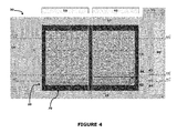
- FIG. 4 the ice protection system 20 is shown with its deicer pad 30 and the underlying wing surface in a flattened form for fluency in explanation.
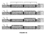
- Figures 4A-4C each show sectional views of this flattened form in different inflation patterns, with layer thicknesses, corner sharpness, and other features being somewhat exaggerated to ease illustration.
- the deicer pad 20 comprises a first chamber 40 and a second chamber 50 which borders the first chamber 40.
- the first chamber 40 is an inboard chamber and the second chamber 50 is an outboard chamber.
- the chambers are situated side-by-side in the spanwise direction (i.e. the inboard-outboard direction).
- a series of adjacent inflation channels 41 are arranged sequentially in the first chamber 40 to extend in a chordwise direction (i.e., in the topside-bottomside direction).
- a manifold channel 42 fluidly communicates with the inflation channels 41 and a connection port 43.
- To place the first chamber 40 is an inflated condition; fluid is supplied through port 43 to the manifold 42 which conveys it to each of the inflation channels 41.
- a series of adjacent inflation channels 51 are arranged sequentially in the first chamber 50 to extend in a chordwise direction.
- a manifold channel 52 fluidly communicates with these inflation channels 51 and with a connection port 53.
- fluid is supplied through the connection port 53 to the manifold 52 which conveys it to each of the inflation channels 51.
- an inflation fluid e.g., air
- air is repeatedly introduced and evacuated from the channels 41/51 to cycle the chambers 40/50 between inflated and deflated conditions. This cycling displaces the boundary layer of ice sheet, thereby breaking it into small pieces which are swept away by the airstream.
- the inflation channels 41 in the first chamber 40 do not fluidly communicate with the inflation channels 51 in the second chamber 50.
- the manifold channel 42 does not fluid communicate with the inflation channels 51 and the manifold channel 52 does not communicate with the inflation channels 41.
- the manifold channels 42 and 52 do not communicate with each other.
- the fluid segregation of the chambers helps insure that a leak (e.g., a puncture) in one chamber does not affect the channel-inflation capabilities of the other chamber.
- a leak e.g., a puncture
- the discrete manifold design allows inflation fluid to be directly routed to channels remote from connection ports.
- the chamber 40 and the chamber 50 are depicted as being of substantially the same size, one chamber's dimensions could dominate the other to further deicing objectives. And although only rectangular-shaped chambers are shown, other regular and irregular chamber geometries are feasible and foreseeable. Additionally or alternatively, the size/shape of the inflation channels can vary from chamber to chamber, and also within individual chambers. Moreover, the deicer pad 30 could comprise additional chambers.
- the deicer pad 30 can comprise an assemblage 60 of material layers 61-66 fabricated and featured to define the inflation channels 41/51, the manifold channels 42/52, and the connection ports 43/53.
- the chamber 40 and the chamber 50 are preferably formed from the same coextensive layers 61-66.
- the layers of the assemblage 60 can include, for example, a base layer 61 (e.g., neoprene), channel-defining layers 62-65 (e.g., rubber coated nylon), and a cover layer 66 (e.g., neoprene).
- a base layer 61 e.g., neoprene
- channel-defining layers 62-65 e.g., rubber coated nylon
- cover layer 66 e.g., neoprene
- the layers 61-66 will usually all be impervious with respect to the inflation fluid.
- the inner layers 61-63 can be non-stretchable to insure that the pad 30 can be securely and trimly mounted to the wing 12.
- the outer layers 64-66 being stretchable to accommodate the inflation and deflation of the channels 41/51.
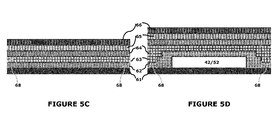
- stitches 67 joining the layers 62-63 to the layers 64-65 define the inflation channels 41/51.
- stitches 68 joining the layer 62 to the layer 63 define the manifold channels 42/52.
- each connection port 43/53 is defined by a hole 69 in the base layer 61 which communicates with the corresponding manifold channel 42/52.
- Each connection port 43/53 can be provided with a fitting having a head 44/54 and a stem 45/55.
- the head 44/54 is sealed within the hole 69 and the stem 45/55 projects outwardly from the base layer 61.
- the stem 45/55 passes through an opening on the surface of the wing 12 and projects into the wing interior.
- the deicer pad 20 can also include a frame 70 comprising a partition portion 71 and perimeter portions 72-75.
- the partition portion 71 is situated along the border between the chamber 40 and the chamber 50 and can contribute to the fluid isolation cause.
- the perimeter portions 72-75 surround the area collectively occupied by the two chambers to fluidly isolate them from the surrounding environment.
- the partition portion 71 can extend between the topside perimeter portion 74 and the bottomside perimeter portion 75.
- the ice protection system 20 can further comprise a source 80 for supplying the deicer connection ports 43 and 53 with inflation fluid during flight.
- Lines 81 and 82 can be plumbed from the inflation-fluid source 80 to the deicer pad's ports 43 and 53, and valves 83 and 84 can be programmed to control fluid flow therethrough.
- the plumbing lines 81 and 82 are both supplied with inflation fluid from a common source 80.
- a common source 80 using separate inflation-fluid sources for each chamber 40/50 is also an option.
- the dual-chamber design of the deicer pad 30 is especially suited for this option, as each chamber can be adapted to best accommodate the inflation fluid supplied thereto.
- an inflation-fluid source 80 commonly resides in the aircraft's fuselage 11, while the pad's connector stems inhabit the wing's interior.
- the lines 81-82 must travel from the fuselage 11 into the wing 12, and then travel to connection ports 43/53. For this reason, inboard deicer connections are often considered the best way to avoid line-plumbing predicaments.
- a wing interior often has many non-deicer components competing for legroom (e.g., ribs, spars, etc.), especially in its inboard regions. Accordingly, options for deicer-connection placement in the chordwise direction (i.e., topside-bottomside) can prove very advantageous during wing design. This flexibility allows more placement-critical components to be given priority, and then deicer connections fitted therearound. This flexibility can also come in handy when an old-style deicer pad (e.g., with hand-laid tubes) is retired from an aircraft and a replacement pad is required.
- legroom e.g., ribs, spars, etc.
- the deicer pad 30 is adapted to allow both the connection port 43 and the connection port 53 to be located on an inboard providence of a chamber.
- the connection ports 43 and 53 are both located on the first chamber 40 near its inboard end.
- the manifold channel 52 passes through the first chamber 40 (without fluidly communicating with the inflation channels 41) on route to the inflation channels 51 in the second channel 50.
- connection port 43 and the connection port 53 are neighboring ports located on an inboard-bottomside site on the chamber 40.
- neighboring connection ports can instead be located on an inboard-topside site, they can be located on a leading-edge-straddling site, or other inboard sites.
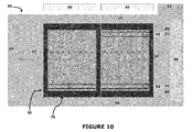
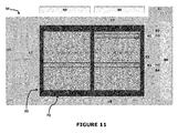
- neighboring connection ports will often facilitate inflation-fluid plumbing, the connection port 43 and the connection port 53 can also be aloof from each other as shown in Figures 10-13 .
- the deicer pads 30 discussed above each comprises spanwise-situated chambers 40/50 having inflation channels 41/51 running in the chordwise direction.
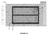
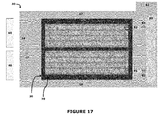
- chordwise-situated chambers 40/50 having inflation channels 41/51 running in the spanwise direction are also possible and producible can offer the same advantages.
- the partition portion 71 of the frame 70 could extend between its inboard perimeter portion 72 and its outboard perimeter portion 73.
- the partition portion 71 may (but need not) coincide with the wing's leading edge 15.
- the deicer pad 30 provides puncture safeguards during flight, offers increased flexibility during wing design, and accommodates wings when old deicing assemblies are retired.
- the aircraft 10, the wing 12, the ice protection system 20, the deicer pad 30, the chamber 40, the chamber 50, the layer assemblage 60, the frame 70, and/or the inflation source 80 have been shown and described as having certain forms and fabrications, such portrayals are not quintessential and represent only some of the possible adaptations of the claimed characteristics.
- Other obvious, equivalent, and/or otherwise akin embodiments could instead be created using the same or analogous attributes.
- the deicer pad 30 can be used on non-wing airfoils, both on an aircraft or not, and inflation-channel alignment is not limited to spanwise and chordwise directions.
Landscapes
- Engineering & Computer Science (AREA)
- Mechanical Engineering (AREA)
- Aviation & Aerospace Engineering (AREA)
- Laminated Bodies (AREA)
- Sealing Devices (AREA)
- Professional, Industrial, Or Sporting Protective Garments (AREA)
- Butt Welding And Welding Of Specific Article (AREA)
Abstract
Description
- An aircraft typically includes an ice protection system to remove ice from its wings during flight. An ice protection system can comprise a deicer pad having inflation channels, a manifold communicating with the inflation channels, and a connection port for supplying inflation fluid to the manifold. To remove accumulated ice from a wing surface, an inflation fluid is repeatedly introduced and evacuated from the channels.
- An ice protection system comprises a deicer pad with fluidly-segregated chambers having inflation channels supplied with fluid by separate manifolds. The deicer pad can be advantageously constructed to accommodate inboard port connections and/or to allow direct routing of inflation fluid to connection-remote channels. And this deicer layout can significantly widen the window of options for chordwise-placement of the connection ports during wing design.
-
-
Figure 1 shows an aircraft having the ice protection apparatus installed on each wing. -
Figures 2-3 show front and sectional views of the wing. -
Figure 4 shows the ice protection apparatus with its deicer pad in a flattened form, andFigures 4A-4C show the deicer pad in different inflation conditions. -
Figure 5 shows a layered assemblage of the deicer pad. -
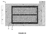
Figures 6-20 show other versions of the ice protection apparatus with its deicer pad in a flattened form. - Referring to
Figures 1-3 , anaircraft 10 comprisesfuselage 11 andwings 12. Thewings 12 each have aninboard end 13 attached to thefuselage 11, anoutboard end 14, a leadingedge 15, atrailing edge 16, atopside 17, and anunderside 18. Theaircraft 10 is provided with anice protection system 20 which includes adeicer pad 30 installed on eachwing 12. Eachdeicer pad 30 curves around its wing's leadingedge 15 in a parabolic-like fashion, so as to cover this stagnation surface and also adjoining surfaces on thetopside 17 and theunderside 18. - Referring to
Figure 4 , theice protection system 20 is shown with itsdeicer pad 30 and the underlying wing surface in a flattened form for fluency in explanation.Figures 4A-4C each show sectional views of this flattened form in different inflation patterns, with layer thicknesses, corner sharpness, and other features being somewhat exaggerated to ease illustration. - The
deicer pad 20 comprises afirst chamber 40 and asecond chamber 50 which borders thefirst chamber 40. Thefirst chamber 40 is an inboard chamber and thesecond chamber 50 is an outboard chamber. In other words, the chambers are situated side-by-side in the spanwise direction (i.e. the inboard-outboard direction). - A series of
adjacent inflation channels 41 are arranged sequentially in thefirst chamber 40 to extend in a chordwise direction (i.e., in the topside-bottomside direction). Amanifold channel 42 fluidly communicates with theinflation channels 41 and aconnection port 43. To place thefirst chamber 40 is an inflated condition; fluid is supplied throughport 43 to themanifold 42 which conveys it to each of theinflation channels 41. - Likewise, a series of
adjacent inflation channels 51 are arranged sequentially in thefirst chamber 50 to extend in a chordwise direction. Amanifold channel 52 fluidly communicates with theseinflation channels 51 and with aconnection port 53. To place thesecond chamber 50 in an inflated condition, fluid is supplied through theconnection port 53 to themanifold 52 which conveys it to each of theinflation channels 51. - To remove a sheet ice from the
wing 12, an inflation fluid (e.g., air) is repeatedly introduced and evacuated from thechannels 41/51 to cycle thechambers 40/50 between inflated and deflated conditions. This cycling displaces the boundary layer of ice sheet, thereby breaking it into small pieces which are swept away by the airstream. - The
inflation channels 41 in thefirst chamber 40 do not fluidly communicate with theinflation channels 51 in thesecond chamber 50. The manifoldchannel 42 does not fluid communicate with theinflation channels 51 and the manifoldchannel 52 does not communicate with theinflation channels 41. And themanifold channels - The fluid segregation of the chambers helps insure that a leak (e.g., a puncture) in one chamber does not affect the channel-inflation capabilities of the other chamber. And the discrete manifold design allows inflation fluid to be directly routed to channels remote from connection ports.
- Although the
chamber 40 and thechamber 50 are depicted as being of substantially the same size, one chamber's dimensions could dominate the other to further deicing objectives. And although only rectangular-shaped chambers are shown, other regular and irregular chamber geometries are feasible and foreseeable. Additionally or alternatively, the size/shape of the inflation channels can vary from chamber to chamber, and also within individual chambers. Moreover, thedeicer pad 30 could comprise additional chambers. - Referring to
Figure 5 , thedeicer pad 30 can comprise anassemblage 60 of material layers 61-66 fabricated and featured to define theinflation channels 41/51, themanifold channels 42/52, and theconnection ports 43/53. Thechamber 40 and thechamber 50 are preferably formed from the same coextensive layers 61-66. - The layers of the
assemblage 60 can include, for example, a base layer 61 (e.g., neoprene), channel-defining layers 62-65 (e.g., rubber coated nylon), and a cover layer 66 (e.g., neoprene). - The layers 61-66 will usually all be impervious with respect to the inflation fluid. The inner layers 61-63 can be non-stretchable to insure that the
pad 30 can be securely and trimly mounted to thewing 12. The outer layers 64-66 being stretchable to accommodate the inflation and deflation of thechannels 41/51. - As shown in
Figures 5A-5B ,stitches 67 joining the layers 62-63 to the layers 64-65 define theinflation channels 41/51. As shown inFigures 5C-5D ,stitches 68 joining thelayer 62 to thelayer 63 define themanifold channels 42/52. - As is shown in
Figure 5E , eachconnection port 43/53 is defined by ahole 69 in thebase layer 61 which communicates with thecorresponding manifold channel 42/52. Eachconnection port 43/53 can be provided with a fitting having a head 44/54 and a stem 45/55. The head 44/54 is sealed within thehole 69 and the stem 45/55 projects outwardly from thebase layer 61. When thedeicer pad 30 is installed on theaircraft 10, the stem 45/55 passes through an opening on the surface of thewing 12 and projects into the wing interior. - Referring back to
Figure 4 , thedeicer pad 20 can also include aframe 70 comprising a partition portion 71 and perimeter portions 72-75. The partition portion 71 is situated along the border between thechamber 40 and thechamber 50 and can contribute to the fluid isolation cause. The perimeter portions 72-75 surround the area collectively occupied by the two chambers to fluidly isolate them from the surrounding environment. With the inboard-outboard chambers shown inFigure 4 , the partition portion 71 can extend between the topside perimeter portion 74 and the bottomside perimeter portion 75. - The
ice protection system 20 can further comprise asource 80 for supplying thedeicer connection ports Lines fluid source 80 to the deicer pad'sports valves - In the illustrated
system 20, theplumbing lines common source 80. However, using separate inflation-fluid sources for eachchamber 40/50 is also an option. In fact, the dual-chamber design of thedeicer pad 30 is especially suited for this option, as each chamber can be adapted to best accommodate the inflation fluid supplied thereto. - In either or any event, an inflation-
fluid source 80 commonly resides in the aircraft'sfuselage 11, while the pad's connector stems inhabit the wing's interior. Thus, the lines 81-82 must travel from thefuselage 11 into thewing 12, and then travel toconnection ports 43/53. For this reason, inboard deicer connections are often considered the best way to avoid line-plumbing predicaments. - A wing interior often has many non-deicer components competing for legroom (e.g., ribs, spars, etc.), especially in its inboard regions. Accordingly, options for deicer-connection placement in the chordwise direction (i.e., topside-bottomside) can prove very advantageous during wing design. This flexibility allows more placement-critical components to be given priority, and then deicer connections fitted therearound. This flexibility can also come in handy when an old-style deicer pad (e.g., with hand-laid tubes) is retired from an aircraft and a replacement pad is required.
- The
deicer pad 30 is adapted to allow both theconnection port 43 and theconnection port 53 to be located on an inboard providence of a chamber. In thepad 30 shown inFigure 4 , for example, theconnection ports first chamber 40 near its inboard end. Themanifold channel 52 passes through the first chamber 40 (without fluidly communicating with the inflation channels 41) on route to theinflation channels 51 in thesecond channel 50. - In the
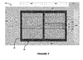
deicer pad 30 shown inFigure 4 , theconnection port 43 and theconnection port 53 are neighboring ports located on an inboard-bottomside site on thechamber 40. As shown inFigure 6-9 , neighboring connection ports can instead be located on an inboard-topside site, they can be located on a leading-edge-straddling site, or other inboard sites. And although neighboring connection ports will often facilitate inflation-fluid plumbing, theconnection port 43 and theconnection port 53 can also be aloof from each other as shown inFigures 10-13 . - The
deicer pads 30 discussed above each comprises spanwise-situatedchambers 40/50 havinginflation channels 41/51 running in the chordwise direction. As shown inFigures 14-20 , chordwise-situatedchambers 40/50 havinginflation channels 41/51 running in the spanwise direction are also possible and producible can offer the same advantages. With this latter layout, the partition portion 71 of theframe 70 could extend between itsinboard perimeter portion 72 and its outboard perimeter portion 73. The partition portion 71 may (but need not) coincide with the wing's leadingedge 15. - One may now appreciate that the
deicer pad 30 provides puncture safeguards during flight, offers increased flexibility during wing design, and accommodates wings when old deicing assemblies are retired. Although theaircraft 10, thewing 12, theice protection system 20, thedeicer pad 30, thechamber 40, thechamber 50, thelayer assemblage 60, theframe 70, and/or theinflation source 80 have been shown and described as having certain forms and fabrications, such portrayals are not quintessential and represent only some of the possible adaptations of the claimed characteristics. Other obvious, equivalent, and/or otherwise akin embodiments could instead be created using the same or analogous attributes. For example, thedeicer pad 30 can be used on non-wing airfoils, both on an aircraft or not, and inflation-channel alignment is not limited to spanwise and chordwise directions. -
- 10
- aircraft
- 11
- fuselage
- 12
- wings
- 13
- inboard end
- 14
- outboard end
- 15
- leading edge
- 16
- trailing edge
- 17
- topside
- 18
- bottomside
- 20
- ice protection system
- 30
- deicer pad
- 40
- first chamber
- 41
- inflation channels in first chamber
- 42
- manifold channel for first chamber
- 43
- connection port for first chamber
- 50
- second chamber
- 51
- inflation channels in second chamber
- 52
- manifold channel for second chamber
- 53
- connection port for second chamber
- 60
- layered assemblage
- 61
- base layer
- 62
- channel-forming layer
- 63
- channel-forming layer
- 64
- channel-forming layer
- 65
- channel-forming layer
- 66
- cover layer
- 67
- inflation-channel stitching
- 68
- manifold-channel stitching
- 69
- connection-port hole
- 70
- frame
- 71
- partition frame portion
- 72
- inboard frame portion
- 73
- outboard frame portion
- 74
- topside frame portion
- 75
- bottomside frame portion
- 80
- inflation-fluid source
- 81
- plumbing line to first chamber
- 82
- plumbing line to second chamber
- 83
- control valve for first chamber
- 84
- control valve for second chamber
Claims (14)
- A deicer pad (30) comprising;
a first chamber (40),
a first series of adjacent inflation channels (41) arranged sequentially in the first chamber (40),
a first manifold channel (42) fluidly communicating with the first series of inflation channels (41),
a first connection port (43) for fluidly connecting the first manifold channel (42) with inflation fluid,
a second chamber (50) bordering the first channel(40),
a second series of adjacent inflation channels (51) arranged sequentially in the second chamber (50),
a second manifold channel (52) fluidly communicating with the second series of inflation channels (51), and
a second connection port (53) for fluidly connecting the second manifold channel (52) with inflation fluid;
wherein:the inflation channels (41) in the first chamber (40) do not communicate with the inflation channels (51) in the second chamber (50),the first manifold channel (42) does not fluidly communicate with the second series of inflation chambers (51), andthe second manifold channel (52) does not fluidly communicate with the first series of inflation chambers (41). - A deicer pad (30) as set forth in the preceding claim, wherein the first connection port (43) is located on an inboard providence of one of the chambers (40/50).
- A deicer pad (30) as set forth in either of the two preceding claims, wherein the second connection port (53) is located on an inboard providence of one of the chambers (40/50).
- A deicer pad (30) as set forth in any of claims 1-3, wherein the first chamber (40) is an inboard chamber and the second chamber (50) is an outboard chamber and the chambers (40,50) are situated side-by-side in the spanwise direction.
- A deicer pad (30) as set forth in the preceding claim, wherein the inflation channels (41) of the first chamber (40) extend in a chordwise direction and wherein the inflation channels (51) of the second chamber (50) also extend in a chordwise direction.
- A deicer pad (30) as set forth in any of claims 1-3, wherein the first chamber (40) is bottomside chamber and the second chamber (50) is a topside chamber and the chambers (40,50) are situated side-by-side in a chordwise direction.
- A deicer pad (30) as set forth in the preceding claim, wherein the inflation channels (41) of the first chamber (40) extend in a spanwise direction and wherein the inflation channels (51) of the second chamber (50) also extend in a spanwise direction.
- A deicer pad (30) as set forth in any of claims 1-7, wherein the first connection port (43) and the second connection port (53) are both located on the same chamber (40/50).
- A deicer pad (30) as set forth in any of claims 1-5 and claims 6-7, wherein the first connection port (43) and the second connection port (53) are located on different chambers (40/50).
- A deicer pad (30) as set forth in any of claims 1-9, wherein the first connection port (43) and the second connection port (53) are both located on an inboard-bottomside site of the same chamber (40).
- A deicer pad (30) as set forth in any of claims 1-9, wherein the first connection port (43) and the second connection port (53) are both located on an inboard-topside site of the same chamber (40).
- A deicer pad (30) as set forth any of claims 1-9, wherein the first connection port (43) and the second connection port (53) straddle the expected location of the leading edge (15).
- An airfoil (12) having an inboard end (13), an outboard end (14), a leading edge (15), a trailing edge (16), a topside (17), and an underside (18), wherein a deicer pad (30) as set forth in any of claims 1-12 is installed around the leading edge (15).
- An aircraft (10) comprising:a fuselage (11);wings (12) wherein each wing (12) has an inboard end (13) attached to the fuselage, an outboard end (14), a leading edge (15), a trailing edge (16), a topside (17), and an underside (18);a deicer pad (30) as set forth in any of claims 1-12 is installed around the leading edge (15) of each wing (12);a source (80) on the fuselage (11) for supplying the connection ports (43,53) of the deicer pad (30) with inflation fluid;a line (81) plumbed from the inflation-fluid source (80) to the first connection port (43); anda line (82) plumbed from the inflation-fluid source (80) to the second connection port (53).
Applications Claiming Priority (1)
| Application Number | Priority Date | Filing Date | Title |
|---|---|---|---|
| US201261593235P | 2012-01-31 | 2012-01-31 |
Publications (2)
| Publication Number | Publication Date |
|---|---|
| EP2623420A2 true EP2623420A2 (en) | 2013-08-07 |
| EP2623420A3 EP2623420A3 (en) | 2017-04-26 |
Family
ID=47713893
Family Applications (1)
| Application Number | Title | Priority Date | Filing Date |
|---|---|---|---|
| EP13153529.6A Withdrawn EP2623420A3 (en) | 2012-01-31 | 2013-01-31 | Aircraft ice protection system |
Country Status (3)
| Country | Link |
|---|---|
| US (1) | US20140224934A1 (en) |
| EP (1) | EP2623420A3 (en) |
| CA (1) | CA2804612A1 (en) |
Families Citing this family (3)
| Publication number | Priority date | Publication date | Assignee | Title |
|---|---|---|---|---|
| US9851020B2 (en) | 2014-12-11 | 2017-12-26 | Goodrich Corporation | Heated valve |
| US10640217B2 (en) * | 2017-07-14 | 2020-05-05 | Goodrich Corporation | Pneumatic deicer with sensors |
| CN113530896B (en) * | 2021-05-31 | 2024-07-23 | 武汉船用机械有限责任公司 | Fuel tank and hydraulic system |
Family Cites Families (9)
| Publication number | Priority date | Publication date | Assignee | Title |
|---|---|---|---|---|
| US2478492A (en) * | 1942-01-30 | 1949-08-09 | Bendix Aviat Corp | Ice eliminating system |
| US2436889A (en) * | 1944-06-09 | 1948-03-02 | Goodrich Co B F | Protective apparatus for preventing accumulation of ice on airfoils |
| US2440240A (en) * | 1944-12-29 | 1948-04-27 | Goodrich Co B F | Protective covering for preventing accumulation of ice on airfoils |
| US2446328A (en) * | 1945-05-01 | 1948-08-03 | Goodrich Co B F | Protective apparatus for preventing the accumulation of ice on airfoils |
| US2599059A (en) * | 1945-07-31 | 1952-06-03 | Goodrich Co B F | Means for preventing ice accumulation on airfoils |
| US2568669A (en) * | 1948-01-23 | 1951-09-18 | Goodrich Co B F | Inflatable covering for surfaces |
| GB2167723B (en) * | 1984-12-03 | 1988-09-21 | Goodrich Co B F | Pneumatic deicer |
| US5449133A (en) * | 1993-07-30 | 1995-09-12 | The B. F. Goodrich Company | Pneumatic de-icer having improved aerodynamic characteristics |
| US6283411B1 (en) * | 1998-01-21 | 2001-09-04 | The B.F. Goodrich Company | Hybrid deicer with element sequence control |
-
2013
- 2013-01-31 US US13/754,923 patent/US20140224934A1/en not_active Abandoned
- 2013-01-31 CA CA 2804612 patent/CA2804612A1/en not_active Abandoned
- 2013-01-31 EP EP13153529.6A patent/EP2623420A3/en not_active Withdrawn
Non-Patent Citations (1)
| Title |
|---|
| None |
Also Published As
| Publication number | Publication date |
|---|---|
| EP2623420A3 (en) | 2017-04-26 |
| CA2804612A1 (en) | 2013-07-31 |
| US20140224934A1 (en) | 2014-08-14 |
Similar Documents
| Publication | Publication Date | Title |
|---|---|---|
| US9364939B2 (en) | Device for the temporary position fixing of aircraft structures to be interconnected | |
| US20140224934A1 (en) | Aircraft ice protection system | |
| CN100445039C (en) | Conformal vacuum cup apparatus and method for removably attaching a rail to a workpiece surface | |
| US6443394B1 (en) | Inflatable airfoil device | |
| US8857562B2 (en) | Standardised insulation device for an aircraft and processes of making and using thereof | |
| US10640217B2 (en) | Pneumatic deicer with sensors | |
| ES2399173T3 (en) | Aircraft pressure bulkhead | |
| US10780983B2 (en) | Sewn alternate inflate pneumatic de-icer | |
| US10669034B2 (en) | Tube type pneumatic deicers | |
| ES2672376T3 (en) | Configuration to maintain the flow to an air inlet of an auxiliary power unit assembly | |
| EP2886453B1 (en) | Boundary layer control system and aircraft having such a boundary layer control system | |
| BR112015004435B1 (en) | autoclave apparatus for curing composite stiffeners against a composite film, and method for curing composite stiffeners and a film within an autoclave | |
| EP3738884B1 (en) | Pneumatic deicer with runback channels | |
| BRPI0707829A2 (en) | double wall floor segment for a travel device to accommodate system components | |
| US20240060296A1 (en) | Inflatable partition | |
| EP2902229A1 (en) | Door construction with gap sealing device and method for sealing a gap between a door and a door frame | |
| EP3156322B1 (en) | Frame insulation providing enhanced drainage features | |
| US7658595B2 (en) | Protective boot for a helicopter pitch link | |
| RU2016129261A (en) | DESIGN FOR INSULATION OF THE AIRCRAFT, AIR CONDITIONING SYSTEM AND INSULATION OF THE AIRCRAFT AND METHOD OF OPERATION OF SUCH SYSTEM | |
| CN106314755A (en) | Aircraft external part with inflatable panels | |
| BR102013005078A2 (en) | Defrost, airfoil and aircraft block | |
| US9321519B2 (en) | Support plate for the passage of systems between two zones with different pressurizations of an aircraft | |
| EP4524033A1 (en) | Hot air duct for a bilge area in an aircraft | |
| US11511868B1 (en) | Pneumatic de-icer with reduced non-inflatable area at de-icer edge | |
| EP2953223A1 (en) | Fastening system |
Legal Events
| Date | Code | Title | Description |
|---|---|---|---|
| PUAI | Public reference made under article 153(3) epc to a published international application that has entered the european phase |
Free format text: ORIGINAL CODE: 0009012 |
|
| 17P | Request for examination filed |
Effective date: 20130131 |
|
| AK | Designated contracting states |
Kind code of ref document: A2 Designated state(s): AL AT BE BG CH CY CZ DE DK EE ES FI FR GB GR HR HU IE IS IT LI LT LU LV MC MK MT NL NO PL PT RO RS SE SI SK SM TR |
|
| AX | Request for extension of the european patent |
Extension state: BA ME |
|
| PUAL | Search report despatched |
Free format text: ORIGINAL CODE: 0009013 |
|
| AK | Designated contracting states |
Kind code of ref document: A3 Designated state(s): AL AT BE BG CH CY CZ DE DK EE ES FI FR GB GR HR HU IE IS IT LI LT LU LV MC MK MT NL NO PL PT RO RS SE SI SK SM TR |
|
| AX | Request for extension of the european patent |
Extension state: BA ME |
|
| RIC1 | Information provided on ipc code assigned before grant |
Ipc: B64D 15/16 20060101AFI20170320BHEP |
|
| STAA | Information on the status of an ep patent application or granted ep patent |
Free format text: STATUS: THE APPLICATION IS DEEMED TO BE WITHDRAWN |
|
| 18D | Application deemed to be withdrawn |
Effective date: 20171027 |