EP2623350A1 - Charging port cover, and charging port structure - Google Patents
Charging port cover, and charging port structure Download PDFInfo
- Publication number
- EP2623350A1 EP2623350A1 EP11828603.8A EP11828603A EP2623350A1 EP 2623350 A1 EP2623350 A1 EP 2623350A1 EP 11828603 A EP11828603 A EP 11828603A EP 2623350 A1 EP2623350 A1 EP 2623350A1
- Authority
- EP
- European Patent Office
- Prior art keywords
- cover
- opening
- charging
- lid
- vehicle
- Prior art date
- Legal status (The legal status is an assumption and is not a legal conclusion. Google has not performed a legal analysis and makes no representation as to the accuracy of the status listed.)
- Granted
Links
- 238000003780 insertion Methods 0.000 description 8
- 230000037431 insertion Effects 0.000 description 8
- 238000007789 sealing Methods 0.000 description 8
- 210000004247 hand Anatomy 0.000 description 6
- 210000003811 finger Anatomy 0.000 description 3
- 230000005540 biological transmission Effects 0.000 description 2
- 210000003813 thumb Anatomy 0.000 description 2
- 238000000034 method Methods 0.000 description 1
- 238000012986 modification Methods 0.000 description 1
- 230000004048 modification Effects 0.000 description 1
- 230000002093 peripheral effect Effects 0.000 description 1
Images





Classifications
-
- B—PERFORMING OPERATIONS; TRANSPORTING
- B60—VEHICLES IN GENERAL
- B60K—ARRANGEMENT OR MOUNTING OF PROPULSION UNITS OR OF TRANSMISSIONS IN VEHICLES; ARRANGEMENT OR MOUNTING OF PLURAL DIVERSE PRIME-MOVERS IN VEHICLES; AUXILIARY DRIVES FOR VEHICLES; INSTRUMENTATION OR DASHBOARDS FOR VEHICLES; ARRANGEMENTS IN CONNECTION WITH COOLING, AIR INTAKE, GAS EXHAUST OR FUEL SUPPLY OF PROPULSION UNITS IN VEHICLES
- B60K1/00—Arrangement or mounting of electrical propulsion units
- B60K1/04—Arrangement or mounting of electrical propulsion units of the electric storage means for propulsion
-
- B—PERFORMING OPERATIONS; TRANSPORTING
- B60—VEHICLES IN GENERAL
- B60K—ARRANGEMENT OR MOUNTING OF PROPULSION UNITS OR OF TRANSMISSIONS IN VEHICLES; ARRANGEMENT OR MOUNTING OF PLURAL DIVERSE PRIME-MOVERS IN VEHICLES; AUXILIARY DRIVES FOR VEHICLES; INSTRUMENTATION OR DASHBOARDS FOR VEHICLES; ARRANGEMENTS IN CONNECTION WITH COOLING, AIR INTAKE, GAS EXHAUST OR FUEL SUPPLY OF PROPULSION UNITS IN VEHICLES
- B60K15/00—Arrangement in connection with fuel supply of combustion engines or other fuel consuming energy converters, e.g. fuel cells; Mounting or construction of fuel tanks
- B60K15/03—Fuel tanks
- B60K15/04—Tank inlets
-
- B—PERFORMING OPERATIONS; TRANSPORTING
- B60—VEHICLES IN GENERAL
- B60L—PROPULSION OF ELECTRICALLY-PROPELLED VEHICLES; SUPPLYING ELECTRIC POWER FOR AUXILIARY EQUIPMENT OF ELECTRICALLY-PROPELLED VEHICLES; ELECTRODYNAMIC BRAKE SYSTEMS FOR VEHICLES IN GENERAL; MAGNETIC SUSPENSION OR LEVITATION FOR VEHICLES; MONITORING OPERATING VARIABLES OF ELECTRICALLY-PROPELLED VEHICLES; ELECTRIC SAFETY DEVICES FOR ELECTRICALLY-PROPELLED VEHICLES
- B60L53/00—Methods of charging batteries, specially adapted for electric vehicles; Charging stations or on-board charging equipment therefor; Exchange of energy storage elements in electric vehicles
- B60L53/10—Methods of charging batteries, specially adapted for electric vehicles; Charging stations or on-board charging equipment therefor; Exchange of energy storage elements in electric vehicles characterised by the energy transfer between the charging station and the vehicle
- B60L53/14—Conductive energy transfer
- B60L53/16—Connectors, e.g. plugs or sockets, specially adapted for charging electric vehicles
-
- H—ELECTRICITY
- H02—GENERATION; CONVERSION OR DISTRIBUTION OF ELECTRIC POWER
- H02G—INSTALLATION OF ELECTRIC CABLES OR LINES, OR OF COMBINED OPTICAL AND ELECTRIC CABLES OR LINES
- H02G3/00—Installations of electric cables or lines or protective tubing therefor in or on buildings, equivalent structures or vehicles
- H02G3/02—Details
- H02G3/08—Distribution boxes; Connection or junction boxes
- H02G3/14—Fastening of cover or lid to box
-
- B—PERFORMING OPERATIONS; TRANSPORTING
- B60—VEHICLES IN GENERAL
- B60K—ARRANGEMENT OR MOUNTING OF PROPULSION UNITS OR OF TRANSMISSIONS IN VEHICLES; ARRANGEMENT OR MOUNTING OF PLURAL DIVERSE PRIME-MOVERS IN VEHICLES; AUXILIARY DRIVES FOR VEHICLES; INSTRUMENTATION OR DASHBOARDS FOR VEHICLES; ARRANGEMENTS IN CONNECTION WITH COOLING, AIR INTAKE, GAS EXHAUST OR FUEL SUPPLY OF PROPULSION UNITS IN VEHICLES
- B60K15/00—Arrangement in connection with fuel supply of combustion engines or other fuel consuming energy converters, e.g. fuel cells; Mounting or construction of fuel tanks
- B60K15/03—Fuel tanks
- B60K15/04—Tank inlets
- B60K15/0406—Filler caps for fuel tanks
- B60K2015/0432—Filler caps for fuel tanks having a specific connection between the cap and the vehicle or tank opening
- B60K2015/0435—Filler caps for fuel tanks having a specific connection between the cap and the vehicle or tank opening using a sliding connection
-
- B—PERFORMING OPERATIONS; TRANSPORTING
- B60—VEHICLES IN GENERAL
- B60K—ARRANGEMENT OR MOUNTING OF PROPULSION UNITS OR OF TRANSMISSIONS IN VEHICLES; ARRANGEMENT OR MOUNTING OF PLURAL DIVERSE PRIME-MOVERS IN VEHICLES; AUXILIARY DRIVES FOR VEHICLES; INSTRUMENTATION OR DASHBOARDS FOR VEHICLES; ARRANGEMENTS IN CONNECTION WITH COOLING, AIR INTAKE, GAS EXHAUST OR FUEL SUPPLY OF PROPULSION UNITS IN VEHICLES
- B60K15/00—Arrangement in connection with fuel supply of combustion engines or other fuel consuming energy converters, e.g. fuel cells; Mounting or construction of fuel tanks
- B60K15/03—Fuel tanks
- B60K15/04—Tank inlets
- B60K15/0406—Filler caps for fuel tanks
- B60K2015/0454—Filler caps for fuel tanks combined closing of the fuel inlet and bodywork inlet by one element which is visible from outside
-
- B—PERFORMING OPERATIONS; TRANSPORTING
- B60—VEHICLES IN GENERAL
- B60K—ARRANGEMENT OR MOUNTING OF PROPULSION UNITS OR OF TRANSMISSIONS IN VEHICLES; ARRANGEMENT OR MOUNTING OF PLURAL DIVERSE PRIME-MOVERS IN VEHICLES; AUXILIARY DRIVES FOR VEHICLES; INSTRUMENTATION OR DASHBOARDS FOR VEHICLES; ARRANGEMENTS IN CONNECTION WITH COOLING, AIR INTAKE, GAS EXHAUST OR FUEL SUPPLY OF PROPULSION UNITS IN VEHICLES
- B60K15/00—Arrangement in connection with fuel supply of combustion engines or other fuel consuming energy converters, e.g. fuel cells; Mounting or construction of fuel tanks
- B60K15/03—Fuel tanks
- B60K15/04—Tank inlets
- B60K15/05—Inlet covers
- B60K2015/0515—Arrangements for closing or opening of inlet cover
- B60K2015/053—Arrangements for closing or opening of inlet cover with hinged connection to the vehicle body
-
- B—PERFORMING OPERATIONS; TRANSPORTING
- B60—VEHICLES IN GENERAL
- B60K—ARRANGEMENT OR MOUNTING OF PROPULSION UNITS OR OF TRANSMISSIONS IN VEHICLES; ARRANGEMENT OR MOUNTING OF PLURAL DIVERSE PRIME-MOVERS IN VEHICLES; AUXILIARY DRIVES FOR VEHICLES; INSTRUMENTATION OR DASHBOARDS FOR VEHICLES; ARRANGEMENTS IN CONNECTION WITH COOLING, AIR INTAKE, GAS EXHAUST OR FUEL SUPPLY OF PROPULSION UNITS IN VEHICLES
- B60K15/00—Arrangement in connection with fuel supply of combustion engines or other fuel consuming energy converters, e.g. fuel cells; Mounting or construction of fuel tanks
- B60K15/03—Fuel tanks
- B60K15/04—Tank inlets
- B60K15/05—Inlet covers
- B60K2015/0553—Details concerning the inlet box or bowl in the vehicle car body panel
-
- B—PERFORMING OPERATIONS; TRANSPORTING
- B60—VEHICLES IN GENERAL
- B60L—PROPULSION OF ELECTRICALLY-PROPELLED VEHICLES; SUPPLYING ELECTRIC POWER FOR AUXILIARY EQUIPMENT OF ELECTRICALLY-PROPELLED VEHICLES; ELECTRODYNAMIC BRAKE SYSTEMS FOR VEHICLES IN GENERAL; MAGNETIC SUSPENSION OR LEVITATION FOR VEHICLES; MONITORING OPERATING VARIABLES OF ELECTRICALLY-PROPELLED VEHICLES; ELECTRIC SAFETY DEVICES FOR ELECTRICALLY-PROPELLED VEHICLES
- B60L2270/00—Problem solutions or means not otherwise provided for
- B60L2270/30—Preventing theft during charging
- B60L2270/32—Preventing theft during charging of electricity
-
- B—PERFORMING OPERATIONS; TRANSPORTING
- B60—VEHICLES IN GENERAL
- B60L—PROPULSION OF ELECTRICALLY-PROPELLED VEHICLES; SUPPLYING ELECTRIC POWER FOR AUXILIARY EQUIPMENT OF ELECTRICALLY-PROPELLED VEHICLES; ELECTRODYNAMIC BRAKE SYSTEMS FOR VEHICLES IN GENERAL; MAGNETIC SUSPENSION OR LEVITATION FOR VEHICLES; MONITORING OPERATING VARIABLES OF ELECTRICALLY-PROPELLED VEHICLES; ELECTRIC SAFETY DEVICES FOR ELECTRICALLY-PROPELLED VEHICLES
- B60L2270/00—Problem solutions or means not otherwise provided for
- B60L2270/30—Preventing theft during charging
- B60L2270/34—Preventing theft during charging of parts
-
- Y—GENERAL TAGGING OF NEW TECHNOLOGICAL DEVELOPMENTS; GENERAL TAGGING OF CROSS-SECTIONAL TECHNOLOGIES SPANNING OVER SEVERAL SECTIONS OF THE IPC; TECHNICAL SUBJECTS COVERED BY FORMER USPC CROSS-REFERENCE ART COLLECTIONS [XRACs] AND DIGESTS
- Y02—TECHNOLOGIES OR APPLICATIONS FOR MITIGATION OR ADAPTATION AGAINST CLIMATE CHANGE
- Y02T—CLIMATE CHANGE MITIGATION TECHNOLOGIES RELATED TO TRANSPORTATION
- Y02T10/00—Road transport of goods or passengers
- Y02T10/60—Other road transportation technologies with climate change mitigation effect
- Y02T10/70—Energy storage systems for electromobility, e.g. batteries
-
- Y—GENERAL TAGGING OF NEW TECHNOLOGICAL DEVELOPMENTS; GENERAL TAGGING OF CROSS-SECTIONAL TECHNOLOGIES SPANNING OVER SEVERAL SECTIONS OF THE IPC; TECHNICAL SUBJECTS COVERED BY FORMER USPC CROSS-REFERENCE ART COLLECTIONS [XRACs] AND DIGESTS
- Y02—TECHNOLOGIES OR APPLICATIONS FOR MITIGATION OR ADAPTATION AGAINST CLIMATE CHANGE
- Y02T—CLIMATE CHANGE MITIGATION TECHNOLOGIES RELATED TO TRANSPORTATION
- Y02T10/00—Road transport of goods or passengers
- Y02T10/60—Other road transportation technologies with climate change mitigation effect
- Y02T10/7072—Electromobility specific charging systems or methods for batteries, ultracapacitors, supercapacitors or double-layer capacitors
-
- Y—GENERAL TAGGING OF NEW TECHNOLOGICAL DEVELOPMENTS; GENERAL TAGGING OF CROSS-SECTIONAL TECHNOLOGIES SPANNING OVER SEVERAL SECTIONS OF THE IPC; TECHNICAL SUBJECTS COVERED BY FORMER USPC CROSS-REFERENCE ART COLLECTIONS [XRACs] AND DIGESTS
- Y02—TECHNOLOGIES OR APPLICATIONS FOR MITIGATION OR ADAPTATION AGAINST CLIMATE CHANGE
- Y02T—CLIMATE CHANGE MITIGATION TECHNOLOGIES RELATED TO TRANSPORTATION
- Y02T90/00—Enabling technologies or technologies with a potential or indirect contribution to GHG emissions mitigation
- Y02T90/10—Technologies relating to charging of electric vehicles
- Y02T90/12—Electric charging stations
-
- Y—GENERAL TAGGING OF NEW TECHNOLOGICAL DEVELOPMENTS; GENERAL TAGGING OF CROSS-SECTIONAL TECHNOLOGIES SPANNING OVER SEVERAL SECTIONS OF THE IPC; TECHNICAL SUBJECTS COVERED BY FORMER USPC CROSS-REFERENCE ART COLLECTIONS [XRACs] AND DIGESTS
- Y02—TECHNOLOGIES OR APPLICATIONS FOR MITIGATION OR ADAPTATION AGAINST CLIMATE CHANGE
- Y02T—CLIMATE CHANGE MITIGATION TECHNOLOGIES RELATED TO TRANSPORTATION
- Y02T90/00—Enabling technologies or technologies with a potential or indirect contribution to GHG emissions mitigation
- Y02T90/10—Technologies relating to charging of electric vehicles
- Y02T90/14—Plug-in electric vehicles
Definitions
- the present invention relates to a charging port cover which closes an open part formed between an opening-closing body in an opened state and a vehicle body when a gun for charging is attached to a charging inlet and charging is performed with the opening-closing body opened from the vehicle body, and relates to a charging port structure.
- An openable and closable lid is provided for an opening portion in the vehicle body, the opening portion including a charging inlet to which a gun for charging is attached, and a gun for charging is attached to a charging inlet with the lid opened.
- the lid is opened from the opening portion of the vehicle body and the gun for charging which is attached to the charging inlet is exposed to the outside from the opening portion which is opened. Accordingly, when charging is performed for a long time, the gun for charging and the like may be tampered with from the outside.
- the open part between the opened lid and the vehicle body may be covered with a cover. In such a case, the cover is required to be provided with a strong lock mechanism.
- an object of the present invention is to strengthen a lock mechanism set for a cover in such a structure that the cover covers an open part formed when an opening portion of a vehicle body which includes a charging inlet is opened by an opening-closing body.
- an engaged member and an engaging member engaging with the engaged member are provided between an opening-closing body and a vehicle body and achieve engagement lock with the vehicle body when the opening-closing body is closed.
- a cover body includes a cover-side engaging member and a cover-side engaged member which engage respectively with the engaged member and the engaging member when the cover body closes the open part formed by opening of the opening-closing body during charging.
- the cover-side engaging member and the cover-side engaged member are integrated with each other by a joining member.
- a bumper 1 is provided in a vehicle front end to extend in a vehicle width direction and a hood 3 covering a motor room from above is provided behind the bumper 1.
- the bumper 1 and the hood 3 form part of a vehicle body.
- a lid 7 which is an opening-closing body capable of being opened and closed in a vertical direction (front-rear direction) is provided in a vehicle-width-direction center portion of a front end of the hood 3 via a pair of lid-side hinges 5 provided respectively on right and left sides.
- the lid 7 is formed in a substantially-trapezoidal shape in a plan view and is formed in such way that the length of a rear edge 9 is larger than the length of a front edge 11 and that side edges 13, 13 are inclined inward in the vehicle width direction toward the front.
- Each of the lid-side hinges 5 includes a first hinge arm 5a, a second hinge arm 5b, and a link bracket 5c protruding rearward and downward from a back surface of the lid 7.
- the first hinge arm 5a is turnably supported at one end (lower end) by the vehicle body and is turnably supported at the other end (upper end) by a vehicle-width-direction outer surface of a lower end of the link bracket 5c.
- the second hinge arm 5b is turnably supported at one end (lower end) by the vehicle body at a position in front of the first hinge arm 5a and is turnably supported at the other end (upper end) by a vehicle-width-direction inner surface of a portion of the link bracket 5c slightly above the lower end of the link bracket 5c (a position closer to the back surface of the lid 7).
- the length from a turning support point of the second hinge arm 5 on the one end side to a turning support point thereof on the other end side is larger than the length from a turning support point of the first hinge arm 5a on the one end side to a turning support point thereof on the other end side.
- the lid 7 is made to move parallel in the front-rear direction while turning about an axis parallel to the vehicle width direction by the lid-side hinges 5 configured as described above, when opened and closed by moving between a fully-closed position (closed position) and a fully-opened position (open position).
- the lid 7 is turned about 90° from the fully-closed position and the rear edge 9 of the lid 7 is located away from a hood front end 3a to an upper front side thereof. Accordingly, a spacious room is provided in a charging-port opening portion 17 to be described later and, in addition, opening-closing operation of the hood 3 can be performed during charging (with a charging gun 30 to be described later inserted in a normal charging inlet 21, for example).
- a charging port 15 is provided in a front end portion of a vehicle-width-direction center portion of the bumper 1.
- the lid 7 is a member sealing the charging-port opening portion 17 which is an opening portion formed in an upper end of the vehicle-width-direction center portion of the bumper 1.
- a quick charging inlet 19 is arranged on a vehicle right side (on the left side when facing it) and the normal charging inlet 21 is arranged on a vehicle left side (on the right side when facing it).
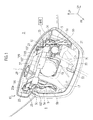
- Fig. 1 shows a state where the charging gun 30 is inserted in the normal charging inlet 21. Charge is completed in a short time when the quick charging inlet 19 is used. Meanwhile, a relatively long time is required for the charge complete when the normal charging inlet 21 is used.
- brackets 23, 23 having an L-shaped cross section are attached to the back surface of the lid 7 and rail members 25, 25 to be described later are attached to vehicle-width-direction outer sides of the brackets 23, 23, respectively.
- a portion 23a of each bracket 23 having the L-shaped cross section are bent in a recessed shape to form a gap between the portion 23a and the back surface of the lid 7.
- a gap sealing member 27 to be described later is inserted in this gap and the lid 7 thereby holds the gap sealing member 27.
- a lid-side striker 29 protruding downward (back surface side of the lid 7) is provided in the vehicle-width-direction center portion of the front end portion of the lid 7 and a striker insertion hole 33 elongating in the front-rear direction is formed at a front end in a vehicle-width-direction center portion of a bottom surface 31 of the charging-port opening portion 17.
- the lid-side striker 29 is formed in a U-shape in a side view. When the lid 7 is closed, the lid-side striker 29 is inserted into the striker insertion hole 33 and then engages with a vehicle-body-side lock unit 34.
- the lid-side striker 29 described above forms an engaging member and the vehicle-body-side lock unit 34 forms an engaged member.
- a charging port cover 35 is attachable to the back surface side of the lid 7 in the opened state.
- Figs. 3 and 4 show the state where the lid 7 is closed together with the charging port cover 35 in the attached state.
- the charging port cover 35 covers both lateral sides of the charging-port opening portion 17 in the vehicle width direction which face in axis directions (vehicle width direction) of the lid-side hinges 5 (see Fig. 1 ) and a front side (vehicle front side) of the lid-side hinges 5.
- each lid-side hinge 5 is a line parallel to a center axis of the turning movement of the lid 7 performed when the lid 7 is opened and closed by moving between the fully-closed position and the fully-opened position.
- the axis directions of the lid-side hinges 5 are directions parallel to the vehicle width direction.
- a portion covered with the charging port cover 35 described above is an open part 36 (see Fig. 11 ) formed between the lid 7 in the opened state (state where the lid 7 is at a position other than the fully-closed position) and the vehicle body (bumper 1 and hood 3) and the charging port cover 35 includes a cover body closing the open part 36.
- the open part 36 can be also referred to as a space defined by the back surface of the lid 7 and the bottom surface 31 of the charging-port opening portion 17 in the state where the lid 7 is opened.
- the gap sealing member 27 provided in the lid 7 prevents insertion of hands and tools into the charging-port opening portion 17 from this gap.
- Fig. 2 shows a state where the lid 7 to which the charging port cover 35 is attached is at the fully-opened position and the lid 7 is at a position between the fully-opened position and the fully-closed position when a cover-side striker 51 of the charging port cover 35 engages with the vehicle-body-side lock unit 34 with the charging port cover 35 attached to the lid 7 as shown in Fig. 3 .
- the charging port cover 35 is formed in a substantial U-shape in a plan view and includes a front face section 37 disposed on a front side in the state where the charging port cover 35 is attached to the vehicle, curved sections 39, 39 curved rearward respectively from right and left ends of the front face section 37, and paired right and left side face sections 41, 41 formed separately from the curved sections 39, 39 and extending rearward respectively from rear ends of the curved sections 39.
- the front face section 37, the curved sections 39, 39, and the side face sections 41, 41 form the cover body.
- a vertically-elongated charging cable cut out 43 extending upward from a lower end of the front face section 37 is provided in a vehicle-left-side portion of the front face section 37.
- a wall-shaped lock mechanism portion 45 protruding to the back surface side (rearward) is formed on the back surface of the vehicle-width-direction center portion of the front face section 37.
- a cable connected to the charging gun 30 (see Fig. 1 ) is inserted in the charging cable cut out 43 during normal charging.
- a lock release lever 47 capable of releasing the engagement between the lock mechanism portion 45 and the lid-side striker 29 provided in the lid 7 is provided on the back surface of a vehicle-right-side portion of the front face section 37.
- the charging cable cut out 43 and the lock release lever 47 are provided on opposite sides to each other with the lock mechanism portion 45 therebetween.
- a striker insertion groove 49 into which the lid-side striker 29 can be inserted is formed at an upper end of the lock mechanism portion 45 and the cover-side striker 51 which is a cover-side engaging member having a substantial U-shape in a side view protrudes downward at a lower end of the lock mechanism portion 45.
- each curved section 39 of the charging port cover 35 is a split portion 53 at which the corresponding side face section 41 is folded inward relative to the curved section 39.
- the striker insertion groove 49 of the charging port cover 35 and the cover-side striker 51 are arranged in a direction (vertical direction in the embodiment) along the opening-closing trajectory of the lid 7.
- the cover-side striker 51 and a hook portion 89 which is an actual locking portion of a lock member 85 (see Fig.
- each side face section 41 is configured to be turnable relative to the corresponding curved section 39 via a side face section side hinge 42.
- opening-closing trajectory is a trajectory which portions of the lid 7 follow when the lid 7 is opened and closed by being moved.
- direction along the opening-closing movement trajectory is a direction parallel to a plane orthogonal to the center axis of the turning movement of the lid 7, i.e.
- “Arranged side by side in a transmission direction of a force acting at the time of locking” refers to an arrangement in which the cover-side striker 51 and hook portion 89 are arranged in such a way that a vector of a force acting on the cover-side striker 51 and a vector of a force acting on the hook portion 89 are at least on the same plane (preferably, on the same straight line) when an external force acts on the lid 7 to move the lid 7 in the fully-opened direction with the lid-side striker 29 and the lock member 85 engaged and locked to each other and with the cover-side striker 51 and the vehicle-body-side lock unit 34 engaged and locked to each other.
- a shielding member 55 is formed on an inner side of each side face section 41 to protrude inward (back surface side).
- the shielding members 55 are provided to prevent entrance of hands and tools from gaps formed in corner portions at right and left ends of the lid rear edge 9 as also shown in Fig. 4 .
- an inner end portion of each shielding member 55 is an inserted engaging member 59 capable of being inserted into and engaging with a groove 57 of a corresponding one of the rail members 25 (see Fig. 1 ) attached to the lid 7 and a lock protrusion 61 is formed at an end of the inserted engaging member 59.
- the shielding member 55, the inserted engaging member 59, and the lock protrusion 61 are formed integrally with the side face section 41. As shown in Fig. 7 , the lock protrusion 61 is configured to be capable of locking with a lock hole 63 formed in an end of the rail member 25.
- a ridge line 65 is formed in the front-rear direction in each of upper and lower portions of the front face section 37, the curved sections 39, and the side face sections 41 in the charging port cover 35.
- an upper end surface 67 and a lower end surface 69 are formed to have arc-shaped cross sections and an intermediate surface 71 between the upper end surface 67 and the lower end surface 69 is formed to be a recessed portion 75 recessed inward from a two-dot chain line 73 connecting the upper end surface 67 and the lower end surface 69 in an arc shape.
- a top surface of the lock mechanism portion 45 is a flat stopper surface 79 with which a contact portion 77 formed at an end of each side face section 41 comes into contact.
- a contact portion 77 formed at an end of each side face section 41 comes into contact.
- the lid-side striker 29 includes a support plate 81 attached to the back surface of the lid 7 and a striker body 83 having a substantial U-shape in a side view and protruding downward from the support plate 81.
- the lock member 85 which is a cover-side engaged member configured to turn together with the lock release lever 47 is turnably supported inside the lock mechanism portion 45 of the charging port cover 35.
- the cover-side striker 51 which is the cover-side engaging member, and the lock member 85 which is the cover-side engaged member are integrated with each other by a wall portion 48 which is a joining member in the lock mechanism portion 45.
- the wall portion 48 is integrated with the back surface of the front face section 37.
- the front face section 37 and the curved sections 39 include an outer member A and an inner member B located on a back surface of the outer member A.
- the members A and B are made to face each other and are then joined and fixed.
- the wall portion 48 is formed integrally with the inner member B, is provided in a vehicle-width-direction center portion of the inner member B to protrude rearward, and extends in the vertical direction in a substantially straight shape.
- the wall portion 48 has a hollow structure having a substantial U-shape whose horizontal cross-sectional shape is opened frontward, and, as shown in Fig.
- the stopper surface 79 which is a rear end face; and paired right and left inclined surfaces 48b which extend to incline in such a way that the distance therebetween becomes larger from right and left edges of the stopper surface 79 toward the back surface of the front face section 37, i.e. general surfaces 48a of the inner member B on both sides of the wall portion 48.
- a lower end portion of the lock member 85 is turnably supported about an axis substantially perpendicular to the front face section 37 via a pin 87 and an upper end portion of the lock member 85 is formed to be the hook portion 89 whose distal end is curved.
- the lock member 85 is pressed in such a direction that the hook portion 89 is locked to the striker body 83 as shown in Fig. 10 , by a torsion coil spring which is provided on the pin 87 and which is not illustrated.
- An arm member 47a protruding toward the lock mechanism portion 45 is provided integrally with the lock release lever 47 on the side close to the lock mechanism portion 45.
- a turn supporting shaft which is not illustrated and which has a shaft center extending in the vertical direction is provided in a distal end portion of the arm member 47a and is turnably supported by the wall portion 48 of the lock mechanism portion 45.
- a lock-member pressing portion 47b curved substantially at a right angle to the arm member 47a in a direction away from the front face section 37 is provided integrally with the arm member 47a.
- a distal end of the lock-member pressing portion 47b can be brought into contact with the side surface of the lock member 85 on the right side in the vehicle width direction (on the left side in Fig. 10 ).
- the lock release lever 47 integrally including the arm member 47a and the lock-member pressing portion 47b is turnable about the turn supporting shaft not illustrated.
- the lock member 85 is housed in the wall portion 48 having a hollow interior, the arm member 47a penetrates one of the inclined surfaces 48b which are side surfaces of the wall portion 48 and the distal end side of the arm member 47a including the lock-member pressing portion 47b is located inside the wall portion 48.
- the hook portion 89 of the lock member 85 is locked to the striker body 83 of the lid-side striker 29.
- the lock release lever 47 is pressed in a direction of the arrow C (direction toward the front face section 37)
- the lock-member pressing portion 47b presses the lock member 85 against a force of the torsion coil spring not illustrated to turn the lock member 85 about the pin 87 and the hook portion 89 is thereby released from the striker body 83.
- the cover-side striker 51 includes a holding bracket 91 made of plastic and a striker body 93 attached to the holding bracket 91 and having a square ring shape in a side view.
- the striker body 93 turns relative to the wall portion 48 about a turning center 52 of the holding bracket 91, together with the holding bracket 91.
- a lower corner 95 of the striker body 93 on a side close to the front face section 37 is an inclined portion 95a curved toward an inner peripheral side.
- the inclined portion 95a is configured to come into contact with an opening edge 97 on a vehicle body side when the charging port cover 35 attached to the lid 7 is closed.
- a front edge 99 of the holding bracket 91 can come into contact with a contact portion 101 of the lock mechanism portion 45. Due to this contact, the holding bracket 91 is prevented from turning frontward (a clockwise direction in Fig. 11 ) but is allowed to turn rearward. Accordingly, the cover-side striker 51 turns only rearward as shown by the arrow D.
- the inclined portion 95a of the striker body 93 comes into contact with the opening edge 97 on the vehicle body side when the charging port cover 35 attached to the lid 7 is closed, and the cover-side striker 51 can thereby turn in the direction of the arrow D while avoiding the opening edge 97 on the vehicle body side which is an obstacle.
- the gap sealing member 27 is formed of a plate-shaped plastic piece which is elastic and formed integrally of: a main body portion 103 formed to be elongated in a lateral direction; and paired right and left locking portions 105, 105 extending upward respectively from right and left ends of the main body portion 103.
- the main body portion 103 includes: general surfaces 107 disposed respectively in an intermediate portion and both end portions; and recessed faces 109 formed between the adjacent general surfaces 107.
- the recessed faces 109 are recessed inward (toward the vehicle rear side) from the general surfaces 107 in the state attached to the lid 7.
- the recessed face 109 on the left side when facing it is a portion to be a recess for a charge gun for quick charging when the charge gun is inserted into the quick charging inlet 19.
- the recessed face 109 on the right side when facing it is a portion to be a recess for the charging gun 30 for normal charging when the charging gun 30 is inserted into the normal charging inlet 21.
- End portions 105a of the locking portions 105 are fitted into gaps between the brackets 23 shown in Fig. 1 and the back surface of the lid 7 and the gap sealing member 27 is thereby held as descried above.
- a lock release lever in the vehicle is operated in the state where the lid 7 is closed and the lock between the lid-side striker 29 and the vehicle-body-side lock unit 34 is released.
- the lid 7 is thereby set to the opened state at the fully-opened position as shown in Fig. 1 .
- charging is performed by attaching the charging gun 30 to the normal charging inlet 21 in this state.
- the charging port cover 35 in which the side face sections 41, 41 are opened relative to the front face section 37 as shown in Fig. 5 is attached to the lid 7 as shown in Fig. 2 with the charging gun 30 attached to the normal charging inlet 21.
- the inserted engaging members 59 of the charging port cover 35 shown in Fig. 6 are inserted into and engaged with the grooves 57 of the rail members 25 shown in Fig. 1 .
- the engagement lock state between the lid-side striker 29 and the lock member 85 is released by turning the lock release lever 47 shown in Figs. 6 and 10 in such a way as to be pressed against the back surface of the front face section 37.
- the work of pressing the lock release lever 47 against the back surface of the front face section 37 is performed by, for example, grabbing portions on both sides of the lock mechanism portion 45 in the front face section 37 of the charging port cover 35 with both hands from below.
- the thumb of each hand is placed on a front surface side of the front face section 37 while the other four fingers of each hand are placed on the back surfaces side of the front face section 37.
- the lock release lever 47 is pressed by at least one of the four fingers on the back surface side.
- Such release work of the lock release lever 47 can be performed easily and is no different from work of simply grabbing the charging port cover 35 with the thumb on the front surface side and the four fingers on the back surface side.
- the lid 7 is closed together with the charging port cover 35 as shown in Figs. 3 and 4 .
- the inclined portion 95a of the striker body 93 in the cover-side striker 51 comes into contact with the opening edge 97 on the vehicle body side.
- the cover-side striker 51 enters the striker insertion hole 33 while turning about the turning center 52 in the direction of the arrow D in Fig. 11 in such a way as to avoid the opening edge 97.
- the cover-side striker 51 engages with the vehicle-body-side lock unit 34 and is thereby locked.
- the charging port cover 35 thus closes the open part 36 formed between the lid 7 and the vehicle body such as the bumper 1 with the lid 7 being at, for example, a half-opened position between the fully-opened position and the fully-closed position. This suppresses entrance of hands and tools into the charging-port opening portion 17 in tampering, particularly at night when charging is performed for a long time.
- the shielding member 55 provided in the charging port cover 35 suppresses entrance of hands and tools into the charging-port opening portion 17 from the gaps formed in the corner portions at the right and left ends of the lid rear edge 9.
- the gap sealing member 27 provided in the lid 7 suppresses insertion of hands and tools into the charging-port opening portion 17 from the gap between the rear edge 9 of the lid 7 and the hood front end 3a.
- the lock release lever in the vehicle is operated and the lock between the cover-side striker 51 of the charging port cover 35 and the vehicle-body-side lock unit 34 in the state shown in Fig. 11 is thereby released.
- the lid 7 is opened together with the charging port cover 35.
- the work of attaching the charging port cover 35 to the lid 7 in Fig. 2 is performed in reverse and the charging port cover 35 is removed from the lid 7.
- the charging gun 30 shown in Fig. 1 is pulled out from the normal charging inlet 21, the normal charging inlet 21 is closed with a cap not illustrated, and then the lid 7 is closed.
- the removed charging port cover 35 is set from the state shown in Fig. 5 to the state shown in Fig. 9 and the side face sections 41, 41 are folded back toward the back surface of the front face section 37 to overlap therewith. At this time, the contact portion 77 at the end of each of the side face sections 41, 41 comes into contact with the stopper surface 79 of the lock mechanism portion 45 and the position of the side face section 41 in the closed state is maintained.
- the cover-side striker 51 being the cover-side engaging member and the lock member 85 being the cover-side engaged member which engage with the lid 7 in the opened state and the vehicle body are integrated with each other by the wall portion 48 which is the joining member of the lock mechanism portion 45.
- the cover-side striker 51 can turn about the turning center 52 relative to the front face section 37 in the direction (direction shown by the arrow D) which is along the opening-closing movement trajectory in opening and closing of the charging port cover 35 together with the lid 7 and which is different from an engagement lock direction of the cover-side striker 51 and the vehicle-body-side lock unit 34, in a state where the lid-side striker 29 and the lock member 85 of the charging port cover 35 are engaged with each other and the charging port cover 35 is thereby attached to the lid 7.
- the lock engagement direction is a direction in which the cover-side striker 51 moves when the cover-side striker 51 engages with the vehicle-body-side lock unit 34 and is, for example, the direction of the arrow E substantially perpendicular to the arrow D of Fig. 11 on a sheet surface.
- the opening-closing movement trajectory is a trajectory which portions of the lid 7 and the charging port cover 35 follow when the lid 7 is moved together with the charging port cover 35 to be opened and closed with the charging port cover 35 attached to the lid 7.
- the direction along the opening-closing movement trajectory is a direction parallel to a plane orthogonal to a line parallel to the center axis of the turning movement of the lid 7, i.e.
- the cover-side striker 51 being turnable in the direction which is along the opening-closing movement trajectory and which is different from the engagement lock direction means that the axis of the turning center 52 of the cover side striker 51 and the center axis of the turning movement of the lid 7 are substantially parallel to each other.
- the cover-side striker 51 can turn in the direction of the arrow in Fig. 11 and be locked while avoiding the opening edge 97 on the vehicle body side which is an obstacle.
- the charging port 15 is provided in the vehicle-width-direction center portion of the bumper 1.
- the position and orientation of the charging port is not limited to this and may be set as appropriate depending on the specifications.
- the charging port may be provided on a side surface of the vehicle body, facing in a lateral direction, or on a rear face of the vehicle body, facing upward.
- the lid 7 is configured to move parallel in the front-rear direction while turning about the axis parallel to the vehicle width direction, when being moved to be closed and opened.
- the mode of opening and closing movement of the lid is not limited to this.
- the turning movement may be performed in the front-rear direction of the vehicle or about an axis parallel to the vertical direction.
- the turning axis may be inclined.
- the cover-side striker 51 is configured to be turnable relative to the front face section 37 about the turning center 52.
- the cover-side striker may be configured to be movable parallel in the front-rear direction relative to the front face section of the cover by providing a rail and a groove in the holding bracket of the cover-side striker and the wall portion holding the holding bracket.
- the lock mechanism of the charging port cover can be strengthened.
Landscapes
- Engineering & Computer Science (AREA)
- Transportation (AREA)
- Mechanical Engineering (AREA)
- Chemical & Material Sciences (AREA)
- Combustion & Propulsion (AREA)
- Life Sciences & Earth Sciences (AREA)
- Sustainable Energy (AREA)
- Sustainable Development (AREA)
- Power Engineering (AREA)
- Architecture (AREA)
- Civil Engineering (AREA)
- Structural Engineering (AREA)
- Electric Propulsion And Braking For Vehicles (AREA)
- Arrangement Or Mounting Of Propulsion Units For Vehicles (AREA)
- Lock And Its Accessories (AREA)
- Charge And Discharge Circuits For Batteries Or The Like (AREA)
Abstract
Description
- The present invention relates to a charging port cover which closes an open part formed between an opening-closing body in an opened state and a vehicle body when a gun for charging is attached to a charging inlet and charging is performed with the opening-closing body opened from the vehicle body, and relates to a charging port structure.
- Conventionally, a battery mounted on an electric vehicle is charged in the following way for example. An openable and closable lid is provided for an opening portion in the vehicle body, the opening portion including a charging inlet to which a gun for charging is attached, and a gun for charging is attached to a charging inlet with the lid opened.
-
- Patent Document 1: Japanese Patent Application Publication No.
Hei 11(1999)-318004 - Incidentally, during charging, the lid is opened from the opening portion of the vehicle body and the gun for charging which is attached to the charging inlet is exposed to the outside from the opening portion which is opened. Accordingly, when charging is performed for a long time, the gun for charging and the like may be tampered with from the outside. To counter this, the open part between the opened lid and the vehicle body may be covered with a cover. In such a case, the cover is required to be provided with a strong lock mechanism.
- In view of this, an object of the present invention is to strengthen a lock mechanism set for a cover in such a structure that the cover covers an open part formed when an opening portion of a vehicle body which includes a charging inlet is opened by an opening-closing body.
- According to one aspect of the present invention, an engaged member and an engaging member engaging with the engaged member are provided between an opening-closing body and a vehicle body and achieve engagement lock with the vehicle body when the opening-closing body is closed. A cover body includes a cover-side engaging member and a cover-side engaged member which engage respectively with the engaged member and the engaging member when the cover body closes the open part formed by opening of the opening-closing body during charging. The cover-side engaging member and the cover-side engaged member are integrated with each other by a joining member.
-
- [
Fig. 1] Fig. 1 is a perspective view showing a charging port in a vehicle front end portion of an embodiment of the present invention and shows a state where a lid is opened. - [
Fig. 2] Fig. 2 is a side view showing a state where a charging port cover of the present invention is attached to the lid ofFig. 1 . - [
Fig. 3] Fig. 3 is a perspective view showing a state where the charging port cover is attached to the lid and is closed. - [
Fig. 4] Fig. 4 is a perspective view in which the lid ofFig. 3 and its vicinity are viewed obliquely from the vehicle rear side. - [
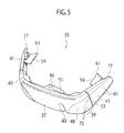
Fig. 5] Fig. 5 is a perspective view in which the charging port cover of the embodiment of the present invention is viewed obliquely from the upper front side. - [
Fig. 6] Fig. 6 is a perspective view in which the charging port cover of the embodiment of the present invention is viewed obliquely from the rear side. - [
Fig. 7] Fig. 7 is an enlarged perspective view showing an inside of a side face portion of the charging port cover. - [
Fig. 8] Fig. 8 is a cross-sectional view of the charging port cover in a curved section. - [
Fig. 9] Fig. 9 is a perspective view in which the charging port cover having the side face sections folded back is viewed from the rear side. - [
Fig. 10] Fig. 10 is a perspective view showing an engagement mechanism of a lid and the vehicle body in the charging port cover. - [
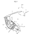
Fig. 11] Fig. 11 is a cross-sectional view showing the state where the lid to which the charging port cover is attached is closed. - [
Fig. 12] Fig. 12 is a perspective view showing a gap sealing member of the embodiment of the present invention. - An embodiment of the present invention is described below in detail together with the drawings. In the embodiment described below, an electric car on which a rechargeable battery is mounted is given as an example. However, the present invention can be applied to a so-called hybrid car on which a battery similar to the one described above is mounted.
- As shown in
Figs. 1 to 4 , abumper 1 is provided in a vehicle front end to extend in a vehicle width direction and ahood 3 covering a motor room from above is provided behind thebumper 1. Thebumper 1 and thehood 3 form part of a vehicle body. - A
lid 7 which is an opening-closing body capable of being opened and closed in a vertical direction (front-rear direction) is provided in a vehicle-width-direction center portion of a front end of thehood 3 via a pair of lid-side hinges 5 provided respectively on right and left sides. Thelid 7 is formed in a substantially-trapezoidal shape in a plan view and is formed in such way that the length of a rear edge 9 is larger than the length of afront edge 11 and thatside edges - Each of the lid-
side hinges 5 includes afirst hinge arm 5a, asecond hinge arm 5b, and alink bracket 5c protruding rearward and downward from a back surface of thelid 7. Thefirst hinge arm 5a is turnably supported at one end (lower end) by the vehicle body and is turnably supported at the other end (upper end) by a vehicle-width-direction outer surface of a lower end of thelink bracket 5c. Meanwhile, thesecond hinge arm 5b is turnably supported at one end (lower end) by the vehicle body at a position in front of thefirst hinge arm 5a and is turnably supported at the other end (upper end) by a vehicle-width-direction inner surface of a portion of thelink bracket 5c slightly above the lower end of thelink bracket 5c (a position closer to the back surface of the lid 7). The length from a turning support point of thesecond hinge arm 5 on the one end side to a turning support point thereof on the other end side is larger than the length from a turning support point of thefirst hinge arm 5a on the one end side to a turning support point thereof on the other end side. Moreover, the distance between the turning support point of thefirst hinge arm 5a on the one end side and the turning support point of thesecond hinge arm 5b on the one end side is larger than the distance between the turning support point of thefirst hinge arm 5a on the other end side and the turning support point of thesecond hinge arm 5b on the other end side.
Thelid 7 is made to move parallel in the front-rear direction while turning about an axis parallel to the vehicle width direction by the lid-side hinges 5 configured as described above, when opened and closed by moving between a fully-closed position (closed position) and a fully-opened position (open position). At the fully-opened position, thelid 7 is turned about 90° from the fully-closed position and the rear edge 9 of thelid 7 is located away from a hood front end 3a to an upper front side thereof. Accordingly, a spacious room is provided in a charging-port opening portion 17 to be described later and, in addition, opening-closing operation of thehood 3 can be performed during charging (with acharging gun 30 to be described later inserted in anormal charging inlet 21, for example). - Moreover, as shown in
Fig. 1 , acharging port 15 is provided in a front end portion of a vehicle-width-direction center portion of thebumper 1. Thelid 7 is a member sealing the charging-port openingportion 17 which is an opening portion formed in an upper end of the vehicle-width-direction center portion of thebumper 1. Inside the charging-port openingportion 17, aquick charging inlet 19 is arranged on a vehicle right side (on the left side when facing it) and thenormal charging inlet 21 is arranged on a vehicle left side (on the right side when facing it).Fig. 1 shows a state where thecharging gun 30 is inserted in thenormal charging inlet 21. Charge is completed in a short time when thequick charging inlet 19 is used. Meanwhile, a relatively long time is required for the charge complete when thenormal charging inlet 21 is used. - Paired right and
left brackets lid 7 andrail members brackets portion 23a of eachbracket 23 having the L-shaped cross section are bent in a recessed shape to form a gap between theportion 23a and the back surface of thelid 7. Agap sealing member 27 to be described later is inserted in this gap and thelid 7 thereby holds thegap sealing member 27. - Moreover, a lid-
side striker 29 protruding downward (back surface side of the lid 7) is provided in the vehicle-width-direction center portion of the front end portion of thelid 7 and astriker insertion hole 33 elongating in the front-rear direction is formed at a front end in a vehicle-width-direction center portion of abottom surface 31 of the charging-port openingportion 17. The lid-side striker 29 is formed in a U-shape in a side view. When thelid 7 is closed, the lid-side striker 29 is inserted into thestriker insertion hole 33 and then engages with a vehicle-body-side lock unit 34. - The lid-
side striker 29 described above forms an engaging member and the vehicle-body-side lock unit 34 forms an engaged member. - Moreover, as shown in
Fig. 2 , acharging port cover 35 is attachable to the back surface side of thelid 7 in the opened state.Figs. 3 and4 show the state where thelid 7 is closed together with thecharging port cover 35 in the attached state. In the state ofFigs. 3 and4 , thecharging port cover 35 covers both lateral sides of the charging-port openingportion 17 in the vehicle width direction which face in axis directions (vehicle width direction) of the lid-side hinges 5 (seeFig. 1 ) and a front side (vehicle front side) of the lid-side hinges 5. The axis of each lid-side hinge 5 is a line parallel to a center axis of the turning movement of thelid 7 performed when thelid 7 is opened and closed by moving between the fully-closed position and the fully-opened position. In the embodiment, the axis directions of the lid-side hinges 5 are directions parallel to the vehicle width direction. - A portion covered with the charging
port cover 35 described above is an open part 36 (seeFig. 11 ) formed between thelid 7 in the opened state (state where thelid 7 is at a position other than the fully-closed position) and the vehicle body (bumper 1 and hood 3) and the chargingport cover 35 includes a cover body closing theopen part 36. In the embodiment, theopen part 36 can be also referred to as a space defined by the back surface of thelid 7 and thebottom surface 31 of the charging-port opening portion 17 in the state where thelid 7 is opened. - Moreover, as shown in
Fig. 4 , although a gap is formed in the vertical direction between the hood front end 3a and the rear edge 9 of thelid 7 to which the chargingport cover 35 is attached, thegap sealing member 27 provided in thelid 7 prevents insertion of hands and tools into the charging-port opening portion 17 from this gap. - Note that
Fig. 2 shows a state where thelid 7 to which the chargingport cover 35 is attached is at the fully-opened position and thelid 7 is at a position between the fully-opened position and the fully-closed position when a cover-side striker 51 of the chargingport cover 35 engages with the vehicle-body-side lock unit 34 with the chargingport cover 35 attached to thelid 7 as shown inFig. 3 . - Next, the charging
port cover 35 of the embodiment is described. - As shown in
Figs. 5 and6 , the chargingport cover 35 is formed in a substantial U-shape in a plan view and includes afront face section 37 disposed on a front side in the state where the chargingport cover 35 is attached to the vehicle,curved sections front face section 37, and paired right and leftside face sections curved sections curved sections 39. Thefront face section 37, thecurved sections side face sections - A vertically-elongated charging cable cut out 43 extending upward from a lower end of the
front face section 37 is provided in a vehicle-left-side portion of thefront face section 37. A wall-shapedlock mechanism portion 45 protruding to the back surface side (rearward) is formed on the back surface of the vehicle-width-direction center portion of thefront face section 37. A cable connected to the charging gun 30 (seeFig. 1 ) is inserted in the charging cable cut out 43 during normal charging. - A
lock release lever 47 capable of releasing the engagement between thelock mechanism portion 45 and the lid-side striker 29 provided in thelid 7 is provided on the back surface of a vehicle-right-side portion of thefront face section 37. In other words, the charging cable cut out 43 and thelock release lever 47 are provided on opposite sides to each other with thelock mechanism portion 45 therebetween. Moreover, astriker insertion groove 49 into which the lid-side striker 29 can be inserted is formed at an upper end of thelock mechanism portion 45 and the cover-side striker 51 which is a cover-side engaging member having a substantial U-shape in a side view protrudes downward at a lower end of thelock mechanism portion 45. - As shown in
Fig. 5 , a rear end of eachcurved section 39 of the chargingport cover 35 is asplit portion 53 at which the correspondingside face section 41 is folded inward relative to thecurved section 39. As shown inFig. 6 , in the state where the chargingport cover 35 is attached to thelid 7, thestriker insertion groove 49 of the chargingport cover 35 and the cover-side striker 51 are arranged in a direction (vertical direction in the embodiment) along the opening-closing trajectory of thelid 7. In other words, the cover-side striker 51 and ahook portion 89 which is an actual locking portion of a lock member 85 (seeFig. 10 ) to be described later are arranged side by side in the direction (vertical direction) along the opening-closing trajectory of thelid 7 and are arranged side by side in a transmission direction of a force acting at the time of locking. Moreover, eachside face section 41 is configured to be turnable relative to the correspondingcurved section 39 via a side facesection side hinge 42. Note that "opening-closing trajectory" is a trajectory which portions of thelid 7 follow when thelid 7 is opened and closed by being moved. Moreover, "direction along the opening-closing movement trajectory" is a direction parallel to a plane orthogonal to the center axis of the turning movement of thelid 7, i.e. a direction orthogonal to a line parallel to the center axis of the turning movement, and includes the vertical direction as in the embodiment. "Arranged side by side in a transmission direction of a force acting at the time of locking" refers to an arrangement in which the cover-side striker 51 andhook portion 89 are arranged in such a way that a vector of a force acting on the cover-side striker 51 and a vector of a force acting on thehook portion 89 are at least on the same plane (preferably, on the same straight line) when an external force acts on thelid 7 to move thelid 7 in the fully-opened direction with the lid-side striker 29 and thelock member 85 engaged and locked to each other and with the cover-side striker 51 and the vehicle-body-side lock unit 34 engaged and locked to each other. - Moreover, as shown in
Figs. 6 and7 , a shieldingmember 55 is formed on an inner side of eachside face section 41 to protrude inward (back surface side). The shieldingmembers 55 are provided to prevent entrance of hands and tools from gaps formed in corner portions at right and left ends of the lid rear edge 9 as also shown inFig. 4 . Moreover, an inner end portion of each shieldingmember 55 is an inserted engagingmember 59 capable of being inserted into and engaging with agroove 57 of a corresponding one of the rail members 25 (seeFig. 1 ) attached to thelid 7 and alock protrusion 61 is formed at an end of the inserted engagingmember 59. The shieldingmember 55, the inserted engagingmember 59, and thelock protrusion 61 are formed integrally with theside face section 41. As shown inFig. 7 , thelock protrusion 61 is configured to be capable of locking with alock hole 63 formed in an end of therail member 25. - As shown in
Fig. 5 , aridge line 65 is formed in the front-rear direction in each of upper and lower portions of thefront face section 37, thecurved sections 39, and theside face sections 41 in the chargingport cover 35. Specifically, as shown inFig. 8 , in eachcurved section 39 for example, anupper end surface 67 and alower end surface 69 are formed to have arc-shaped cross sections and anintermediate surface 71 between theupper end surface 67 and thelower end surface 69 is formed to be a recessedportion 75 recessed inward from a two-dot chain line 73 connecting theupper end surface 67 and thelower end surface 69 in an arc shape. - Moreover, as shown in
Fig. 6 , a top surface of thelock mechanism portion 45 is aflat stopper surface 79 with which acontact portion 77 formed at an end of eachside face section 41 comes into contact. Specifically, as shown inFig. 9 , when the right and leftside face sections front face section 37, thecontact portion 77 of eachside face section 41 comes into contact with thestopper surface 79 of thelock mechanism portion 45 and the position of theside face section 41 in the closed state is maintained. - As shown in
Fig. 10 , the lid-side striker 29 includes a support plate 81 attached to the back surface of thelid 7 and astriker body 83 having a substantial U-shape in a side view and protruding downward from the support plate 81. Thelock member 85 which is a cover-side engaged member configured to turn together with thelock release lever 47 is turnably supported inside thelock mechanism portion 45 of the chargingport cover 35. - Specifically, the cover-
side striker 51 which is the cover-side engaging member, and thelock member 85 which is the cover-side engaged member are integrated with each other by awall portion 48 which is a joining member in thelock mechanism portion 45. Note that thewall portion 48 is integrated with the back surface of thefront face section 37. - As shown in
Fig. 8 , thefront face section 37 and thecurved sections 39 include an outer member A and an inner member B located on a back surface of the outer member A. The members A and B are made to face each other and are then joined and fixed. Thewall portion 48 is formed integrally with the inner member B, is provided in a vehicle-width-direction center portion of the inner member B to protrude rearward, and extends in the vertical direction in a substantially straight shape. Moreover, thewall portion 48 has a hollow structure having a substantial U-shape whose horizontal cross-sectional shape is opened frontward, and, as shown inFig. 6 , includes: thestopper surface 79 which is a rear end face; and paired right and leftinclined surfaces 48b which extend to incline in such a way that the distance therebetween becomes larger from right and left edges of thestopper surface 79 toward the back surface of thefront face section 37, i.e.general surfaces 48a of the inner member B on both sides of thewall portion 48. - A lower end portion of the
lock member 85 is turnably supported about an axis substantially perpendicular to thefront face section 37 via apin 87 and an upper end portion of thelock member 85 is formed to be thehook portion 89 whose distal end is curved. Thelock member 85 is pressed in such a direction that thehook portion 89 is locked to thestriker body 83 as shown inFig. 10 , by a torsion coil spring which is provided on thepin 87 and which is not illustrated. - An
arm member 47a protruding toward thelock mechanism portion 45 is provided integrally with thelock release lever 47 on the side close to thelock mechanism portion 45. A turn supporting shaft which is not illustrated and which has a shaft center extending in the vertical direction is provided in a distal end portion of thearm member 47a and is turnably supported by thewall portion 48 of thelock mechanism portion 45. Furthermore, a lock-member pressing portion 47b curved substantially at a right angle to thearm member 47a in a direction away from thefront face section 37 is provided integrally with thearm member 47a. A distal end of the lock-member pressing portion 47b can be brought into contact with the side surface of thelock member 85 on the right side in the vehicle width direction (on the left side inFig. 10 ). In other words, thelock release lever 47 integrally including thearm member 47a and the lock-member pressing portion 47b is turnable about the turn supporting shaft not illustrated. - Moreover, since the
lock member 85 is housed in thewall portion 48 having a hollow interior, thearm member 47a penetrates one of theinclined surfaces 48b which are side surfaces of thewall portion 48 and the distal end side of thearm member 47a including the lock-member pressing portion 47b is located inside thewall portion 48. - In the normal state, the
hook portion 89 of thelock member 85 is locked to thestriker body 83 of the lid-side striker 29. When thelock release lever 47 is pressed in a direction of the arrow C (direction toward the front face section 37), the lock-member pressing portion 47b presses thelock member 85 against a force of the torsion coil spring not illustrated to turn thelock member 85 about thepin 87 and thehook portion 89 is thereby released from thestriker body 83. - As shown in
Figs. 10 and11 , the cover-side striker 51 includes a holdingbracket 91 made of plastic and astriker body 93 attached to the holdingbracket 91 and having a square ring shape in a side view. Thestriker body 93 turns relative to thewall portion 48 about aturning center 52 of the holdingbracket 91, together with the holdingbracket 91. - A
lower corner 95 of thestriker body 93 on a side close to thefront face section 37 is aninclined portion 95a curved toward an inner peripheral side. Theinclined portion 95a is configured to come into contact with an openingedge 97 on a vehicle body side when the chargingport cover 35 attached to thelid 7 is closed. - A
front edge 99 of the holdingbracket 91 can come into contact with acontact portion 101 of thelock mechanism portion 45. Due to this contact, the holdingbracket 91 is prevented from turning frontward (a clockwise direction inFig. 11 ) but is allowed to turn rearward. Accordingly, the cover-side striker 51 turns only rearward as shown by the arrow D. - Specifically, the
inclined portion 95a of thestriker body 93 comes into contact with the openingedge 97 on the vehicle body side when the chargingport cover 35 attached to thelid 7 is closed, and the cover-side striker 51 can thereby turn in the direction of the arrow D while avoiding the openingedge 97 on the vehicle body side which is an obstacle. - As shown in
Fig. 12 , thegap sealing member 27 is formed of a plate-shaped plastic piece which is elastic and formed integrally of: amain body portion 103 formed to be elongated in a lateral direction; and paired right and left lockingportions main body portion 103. Themain body portion 103 includes:general surfaces 107 disposed respectively in an intermediate portion and both end portions; and recessed faces 109 formed between the adjacentgeneral surfaces 107. The recessed faces 109 are recessed inward (toward the vehicle rear side) from thegeneral surfaces 107 in the state attached to thelid 7. The recessedface 109 on the left side when facing it is a portion to be a recess for a charge gun for quick charging when the charge gun is inserted into thequick charging inlet 19. The recessedface 109 on the right side when facing it is a portion to be a recess for the charginggun 30 for normal charging when the charginggun 30 is inserted into thenormal charging inlet 21.End portions 105a of the lockingportions 105 are fitted into gaps between thebrackets 23 shown inFig. 1 and the back surface of thelid 7 and thegap sealing member 27 is thereby held as descried above. - Next, description is given of a charge operation of the battery mounted on the vehicle which is performed by using the
normal charging inlet 21 and which requires a long time. First, a lock release lever in the vehicle is operated in the state where thelid 7 is closed and the lock between the lid-side striker 29 and the vehicle-body-side lock unit 34 is released. Thelid 7 is thereby set to the opened state at the fully-opened position as shown inFig. 1 . Then, charging is performed by attaching the charginggun 30 to thenormal charging inlet 21 in this state. - The charging
port cover 35 in which theside face sections front face section 37 as shown inFig. 5 is attached to thelid 7 as shown inFig. 2 with the charginggun 30 attached to thenormal charging inlet 21. At this time, the inserted engagingmembers 59 of the chargingport cover 35 shown inFig. 6 are inserted into and engaged with thegrooves 57 of therail members 25 shown inFig. 1 . During this insertion, the engagement lock state between the lid-side striker 29 and thelock member 85 is released by turning thelock release lever 47 shown inFigs. 6 and10 in such a way as to be pressed against the back surface of thefront face section 37. - After the inserted engaging
members 59 of the chargingport cover 35 are inserted into thegrooves 57 of therail member 25, the pressing operation of thelock release lever 47 is stopped and the lock-member pressing portion 47b on the distal end side of thelock release lever 47 thereby stops pressing thelock member 85. As a result, thelock member 85 is turned by the torsion coil spring not illustrated and thehook portion 89 is locked to thestriker body 83 as shown inFig. 10 . - The work of pressing the
lock release lever 47 against the back surface of thefront face section 37 is performed by, for example, grabbing portions on both sides of thelock mechanism portion 45 in thefront face section 37 of the chargingport cover 35 with both hands from below. At this time, the thumb of each hand is placed on a front surface side of thefront face section 37 while the other four fingers of each hand are placed on the back surfaces side of thefront face section 37. Then, thelock release lever 47 is pressed by at least one of the four fingers on the back surface side. Such release work of thelock release lever 47 can be performed easily and is no different from work of simply grabbing the chargingport cover 35 with the thumb on the front surface side and the four fingers on the back surface side. - After the charging
port cover 35 is attached and locked to thelid 7, thelid 7 is closed together with the chargingport cover 35 as shown inFigs. 3 and4 . When the chargingport cover 35 is closed, theinclined portion 95a of thestriker body 93 in the cover-side striker 51 comes into contact with the openingedge 97 on the vehicle body side. By this contact, the cover-side striker 51 enters thestriker insertion hole 33 while turning about theturning center 52 in the direction of the arrow D inFig. 11 in such a way as to avoid the openingedge 97. Then, the cover-side striker 51 engages with the vehicle-body-side lock unit 34 and is thereby locked. - As shown in
Fig. 11 , the chargingport cover 35 thus closes theopen part 36 formed between thelid 7 and the vehicle body such as thebumper 1 with thelid 7 being at, for example, a half-opened position between the fully-opened position and the fully-closed position. This suppresses entrance of hands and tools into the charging-port opening portion 17 in tampering, particularly at night when charging is performed for a long time. - At this time, as shown in
Fig. 4 , the shieldingmember 55 provided in the chargingport cover 35 suppresses entrance of hands and tools into the charging-port opening portion 17 from the gaps formed in the corner portions at the right and left ends of the lid rear edge 9. Moreover, thegap sealing member 27 provided in thelid 7 suppresses insertion of hands and tools into the charging-port opening portion 17 from the gap between the rear edge 9 of thelid 7 and the hood front end 3a. - After the charging is completed, the lock release lever in the vehicle is operated and the lock between the cover-
side striker 51 of the chargingport cover 35 and the vehicle-body-side lock unit 34 in the state shown inFig. 11 is thereby released. In this state, thelid 7 is opened together with the chargingport cover 35. - Thereafter, the work of attaching the charging
port cover 35 to thelid 7 inFig. 2 is performed in reverse and the chargingport cover 35 is removed from thelid 7. After the chargingport cover 35 is removed, the charginggun 30 shown inFig. 1 is pulled out from thenormal charging inlet 21, thenormal charging inlet 21 is closed with a cap not illustrated, and then thelid 7 is closed. - The removed charging
port cover 35 is set from the state shown inFig. 5 to the state shown inFig. 9 and theside face sections front face section 37 to overlap therewith. At this time, thecontact portion 77 at the end of each of theside face sections stopper surface 79 of thelock mechanism portion 45 and the position of theside face section 41 in the closed state is maintained. - In the charging
port cover 35 of the embodiment, the cover-side striker 51 being the cover-side engaging member and thelock member 85 being the cover-side engaged member which engage with thelid 7 in the opened state and the vehicle body are integrated with each other by thewall portion 48 which is the joining member of thelock mechanism portion 45. - This strengthens the lock mechanism of the charging
port cover 35 compared to the configuration in which the cover-side striker 51 and thelock member 85 are separately attached to thefront face section 37. Moreover, the distance between the cover-side striker 51 and thelock member 85 can be accurately secured by integrating the cover-side striker 51 and thelock member 85 with each other by thewall portion 48. As result, the lid-side striker 29 and the vehicle-body-side lock unit 34 can be locked to each other more surely with the chargingport cover 35 closing theopen part 36. - Moreover, in the embodiment, the cover-
side striker 51 can turn about theturning center 52 relative to thefront face section 37 in the direction (direction shown by the arrow D) which is along the opening-closing movement trajectory in opening and closing of the chargingport cover 35 together with thelid 7 and which is different from an engagement lock direction of the cover-side striker 51 and the vehicle-body-side lock unit 34, in a state where the lid-side striker 29 and thelock member 85 of the chargingport cover 35 are engaged with each other and the chargingport cover 35 is thereby attached to thelid 7. The lock engagement direction is a direction in which the cover-side striker 51 moves when the cover-side striker 51 engages with the vehicle-body-side lock unit 34 and is, for example, the direction of the arrow E substantially perpendicular to the arrow D ofFig. 11 on a sheet surface. The opening-closing movement trajectory is a trajectory which portions of thelid 7 and the chargingport cover 35 follow when thelid 7 is moved together with the chargingport cover 35 to be opened and closed with the chargingport cover 35 attached to thelid 7. The direction along the opening-closing movement trajectory is a direction parallel to a plane orthogonal to a line parallel to the center axis of the turning movement of thelid 7, i.e. a direction orthogonal to a line parallel to the center axis of the turning movement. Accordingly, the cover-side striker 51 being turnable in the direction which is along the opening-closing movement trajectory and which is different from the engagement lock direction means that the axis of theturning center 52 of thecover side striker 51 and the center axis of the turning movement of thelid 7 are substantially parallel to each other. - Accordingly, when the charging
port cover 35 attached to thelid 7 is closed and theinclined portion 95a of thestriker body 93 comes into contact with the openingedge 97 on the vehicle body side, the cover-side striker 51 can turn in the direction of the arrow inFig. 11 and be locked while avoiding the openingedge 97 on the vehicle body side which is an obstacle. - The embodiment of the present invention has been described above. However, the embodiment is merely an example described to facilitate the understanding of the present invention and the present invention is not limited to the embodiment. The technical scope of the present invention is not limited to the specific technical matters disclosed in the embodiment and includes various modifications, changes, and alternative techniques which can be easily derived therefrom. For example, in the embodiment, the charging
port 15 is provided in the vehicle-width-direction center portion of thebumper 1. However, the position and orientation of the charging port is not limited to this and may be set as appropriate depending on the specifications. For example, the charging port may be provided on a side surface of the vehicle body, facing in a lateral direction, or on a rear face of the vehicle body, facing upward. Moreover, in the embodiment, thelid 7 is configured to move parallel in the front-rear direction while turning about the axis parallel to the vehicle width direction, when being moved to be closed and opened. However, the mode of opening and closing movement of the lid is not limited to this. For example, the turning movement may be performed in the front-rear direction of the vehicle or about an axis parallel to the vertical direction. Furthermore, the turning axis may be inclined. In the embodiment, the cover-side striker 51 is configured to be turnable relative to thefront face section 37 about theturning center 52. However, the cover-side striker may be configured to be movable parallel in the front-rear direction relative to the front face section of the cover by providing a rail and a groove in the holding bracket of the cover-side striker and the wall portion holding the holding bracket. - This application claims priority based on Japanese Patent Application No.
2010-223796 filed on October 1, 2010 - In the invention, since the cover-side engaged member and the cover-side engaging member which engage with the closing-opening body in the opened state and the vehicle body are integrated with each other by the joining member, the lock mechanism of the charging port cover can be strengthened.
-
- 1
- bumper (vehicle body)
- 3
- hood (vehicle body)
- 7
- lid (opening-closing body)
- 17
- charging-port opening portion (opening portion)
- 21
- normal charging inlet
- 29
- lid-side striker (engaging member)
- 30
- charging gun
- 34
- vehicle-body-side lock unit (engaged member)
- 36
- open part formed between lid and vehicle body
- 37
- front face section of charge port cover (cover body)
- 39
- curved section of charge port cover (cover body)
- 41
- side face section of charge port cover (cover body)
- 45
- lock mechanism portion (joining member)
- 51
- cover-side striker (cover-side engaging member)
- 85
- lock member (cover-side engaged member)
Claims (3)
- A charging port cover comprising a cover body closing an open part formed between an opening-closing body and a vehicle body in a state where the opening-closing body is opened when a gun for charging is attached to a charging inlet and charging for a battery mounted on a vehicle is performed, the opening-closing body capable of opening and closing an opening portion which is provided in the vehicle body of the vehicle and which includes the charging inlet, wherein
the cover body includes a cover-side engaging member and a cover-side engaged member which engage respectively with an engaged member and an engaging member configured to engage with the engaged member, when the open part is closed, the engaged member and the engaging member provided between the opening-closing body and the vehicle body and configured to engage and lock the closed opening-closing body with the vehicle body, and
the cover-side engaging member and the cover-side engaged member are integrated with each other by a joining member. - The charging port cover according to claim 1, wherein
the cover body includes the cover-side engaged member with which the engaging member provided in the opening-closing body engages and the cover-side engaging member which engages with the engaged member provided in the vehicle body, and
the cover-side engaging member is capable of moving relative to the cover body in a direction which is along an opening-closing movement trajectory of the cover body being opened and closed together with the opening-closing body and which is different from an engagement lock direction of the cover-side engaging member and the engaged member of the vehicle body, in a state where the engaging member of the opening-closing body and the cover-side engaged member are engaged with each other and the cover body is thereby attached to the opening-closing body. - A charging port structure comprising:a charging inlet which is disposed in an opening portion provided in a vehicle body and to which a gun for charging a battery mounted on a vehicle is attached;an opening-closing body which is provided in the vehicle body and which is capable of being opened and closed by being moved between an opened position where the opening portion is opened and a closed position where the opening portion is closed;an engaged member and an engaging member configured to engage with the engaged member, the engaged member and the engaging member provided between the opening-closing body and the vehicle body and configured to engage and lock the opening-closing body at the closed position with the vehicle body;a cover body which is disposed between the vehicle body and the opening-closing body at a position other than the closed position and which closes an open part formed between the opening-closing body and the vehicle body;a cover-side engaging member and a cover-side engaged member which are provided in the cover body and which engage respectively with the engaged member and the engaging member when the cover body closes the open part; anda joining member which is provided in the cover body and which integrates the cover-side engaging member and the cover-side engaged member with each other.
Applications Claiming Priority (2)
| Application Number | Priority Date | Filing Date | Title |
|---|---|---|---|
| JP2010223796A JP5617506B2 (en) | 2010-10-01 | 2010-10-01 | Charging port cover |
| PCT/JP2011/067089 WO2012043042A1 (en) | 2010-10-01 | 2011-07-27 | Charging port cover, and charging port structure |
Publications (3)
| Publication Number | Publication Date |
|---|---|
| EP2623350A1 true EP2623350A1 (en) | 2013-08-07 |
| EP2623350A4 EP2623350A4 (en) | 2018-05-16 |
| EP2623350B1 EP2623350B1 (en) | 2019-04-03 |
Family
ID=45892519
Family Applications (1)
| Application Number | Title | Priority Date | Filing Date |
|---|---|---|---|
| EP11828603.8A Not-in-force EP2623350B1 (en) | 2010-10-01 | 2011-07-27 | Charging port cover, and charging port structure |
Country Status (9)
| Country | Link |
|---|---|
| US (1) | US8870582B2 (en) |
| EP (1) | EP2623350B1 (en) |
| JP (1) | JP5617506B2 (en) |
| CN (1) | CN103079859B (en) |
| BR (1) | BR112013005313A2 (en) |
| MX (1) | MX2013002742A (en) |
| MY (1) | MY159642A (en) |
| RU (1) | RU2536034C1 (en) |
| WO (1) | WO2012043042A1 (en) |
Cited By (2)
| Publication number | Priority date | Publication date | Assignee | Title |
|---|---|---|---|---|
| CN103754273A (en) * | 2014-02-11 | 2014-04-30 | 安徽江淮汽车股份有限公司 | Electric vehicle charging port cap |
| DE102018117226A1 (en) | 2018-07-17 | 2020-01-23 | Dr. Ing. H.C. F. Porsche Aktiengesellschaft | Charge connector arrangement of a motor vehicle |
Families Citing this family (27)
| Publication number | Priority date | Publication date | Assignee | Title |
|---|---|---|---|---|
| JP5585362B2 (en) * | 2010-10-01 | 2014-09-10 | 日産自動車株式会社 | Charging port cover arrangement structure |
| JP5585363B2 (en) | 2010-10-01 | 2014-09-10 | 日産自動車株式会社 | Charging port cover arrangement structure |
| JP2013203149A (en) * | 2012-03-27 | 2013-10-07 | Honda Motor Co Ltd | Electric vehicle charging device |
| DE102012014615A1 (en) * | 2012-07-24 | 2014-01-30 | Audi Ag | Locking module for a motor vehicle door of a motor vehicle and corresponding motor vehicle |
| JP5783336B2 (en) * | 2012-09-19 | 2015-09-24 | 日産自動車株式会社 | Charging port structure |
| JP6034171B2 (en) * | 2012-12-13 | 2016-11-30 | 株式会社東海理化電機製作所 | Locking device |
| JP6003614B2 (en) * | 2012-12-18 | 2016-10-05 | 三菱自動車工業株式会社 | Electric vehicle charging unit structure |
| JP6139215B2 (en) * | 2013-03-29 | 2017-05-31 | シーシーアイ株式会社 | Standard substance composition for measuring neutral fat concentration and method for producing the same |
| JP6454466B2 (en) * | 2013-11-11 | 2019-01-16 | 三菱自動車工業株式会社 | Charge control device |
| JP6493659B2 (en) * | 2014-11-19 | 2019-04-03 | 三菱自動車工業株式会社 | Charging port structure |
| JP6009528B2 (en) * | 2014-12-18 | 2016-10-19 | 住友電装株式会社 | Charging inlet |
| DE102015101265A1 (en) * | 2015-01-29 | 2016-08-04 | Phoenix Contact E-Mobility Gmbh | Connectors |
| DE102016106651A1 (en) * | 2016-04-12 | 2017-10-12 | Dr. Ing. H.C. F. Porsche Aktiengesellschaft | Mechanism and method for actuating a loading flap |
| USD860944S1 (en) * | 2016-10-17 | 2019-09-24 | Jaguar Land Rover Limited | Charging hatch |
| KR101985484B1 (en) * | 2018-02-05 | 2019-06-03 | 주식회사 신진화학 | Fuel filler door structure for vehicles |
| KR101985483B1 (en) * | 2018-02-05 | 2019-06-03 | 주식회사 신진화학 | Fuel filler door structure for vehicles |
| CN109017655B (en) * | 2018-08-01 | 2021-08-24 | 奇瑞商用车(安徽)有限公司 | Leading grid structure of new energy automobile |
| JP6764453B2 (en) * | 2018-09-27 | 2020-09-30 | 本田技研工業株式会社 | Body front structure |
| JP6734337B2 (en) * | 2018-09-27 | 2020-08-05 | 本田技研工業株式会社 | Body front structure |
| CN109301591B (en) * | 2018-10-18 | 2020-10-23 | 蔚来(安徽)控股有限公司 | Interface protection component and electric automobile charge |
| US12233733B2 (en) * | 2020-12-09 | 2025-02-25 | Ford Global Technologies, Llc | Electrified vehicle charging station configured to provide parking guidance to electrified vehicles |
| CN115411802A (en) * | 2021-05-28 | 2022-11-29 | 格力博(江苏)股份有限公司 | Locking structure of charging device |
| JP7376545B2 (en) | 2021-09-21 | 2023-11-08 | 豊田合成株式会社 | Drive device for energy supply port parts |
| JP7464572B2 (en) * | 2021-09-22 | 2024-04-09 | 矢崎総業株式会社 | Charging connector |
| US20230313588A1 (en) * | 2022-03-31 | 2023-10-05 | Oshkosh Corporation | Vehicle with port enclosure |
| KR20230153548A (en) * | 2022-04-28 | 2023-11-07 | 현대자동차주식회사 | Charging door assembly for vehicle |
| JP7704070B2 (en) * | 2022-05-23 | 2025-07-08 | 豊田合成株式会社 | Lid device for vehicle |
Family Cites Families (19)
| Publication number | Priority date | Publication date | Assignee | Title |
|---|---|---|---|---|
| US4537437A (en) * | 1983-10-31 | 1985-08-27 | Buccola Anthony A | Nozzle positioner for automatic fuel tank |
| US5280135B1 (en) | 1991-08-09 | 1998-01-20 | Intermatic Inc | Outdoor electrical outlet cover |
| DE19642687C2 (en) * | 1996-10-16 | 1999-08-05 | Daimler Chrysler Ag | Locking device for securing a charging socket |
| DE19832910C2 (en) * | 1997-07-25 | 2003-03-27 | Alfmeier Praez Ag | Locking device for motor vehicle tanks |
| JPH11185861A (en) * | 1997-12-22 | 1999-07-09 | Shirogane Kasei Kk | Cover for outlet |
| JPH11318004A (en) * | 1998-05-07 | 1999-11-16 | Nissan Motor Co Ltd | Automatic operation device for charging lid of electric vehicle |
| JPH11332024A (en) * | 1998-05-12 | 1999-11-30 | Nissan Motor Co Ltd | Electric vehicle charging lid structure |
| DE29823851U1 (en) * | 1998-07-24 | 2000-01-05 | Mannesmann VDO AG, 60388 Frankfurt | Window cleaning system |
| DE10013938C1 (en) * | 2000-03-21 | 2001-12-06 | Wietmarscher Ambulanz Und Sond | Mains connection for emergency vehicle battery recharging has dished housing and cooperating pivoted cover supporting plug-in connection |
| CN2637787Y (en) * | 2003-07-15 | 2004-09-01 | 周金明 | Pressure oil tank cover |
| US7056145B2 (en) * | 2004-03-12 | 2006-06-06 | Campbell Iii Richard G | Plug securing and outlet cover device |
| ITTO20060151A1 (en) * | 2006-03-01 | 2007-09-02 | Fiat Auto Spa | DOOR GROUP FOR THE FUEL TANK OF THE FUEL TANK OF A MOTOR VEHICLE. |
| FR2916090B1 (en) * | 2007-05-11 | 2009-07-17 | Legrand France | SEALED ELECTRICAL CONNECTION DEVICE WITH MULTIPLE CONFIGURATIONS |
| DE102007035491A1 (en) * | 2007-07-28 | 2009-01-29 | GM Global Technology Operations, Inc., Detroit | Tank flap unit |
| DE102007042610A1 (en) * | 2007-09-07 | 2009-03-12 | GM Global Technology Operations, Inc., Detroit | Windscreen covering for e.g. electrical or hybrid vehicles, has cover connected with covering element in closed condition, and electrical connection closed by cover and attached to electrical energy source in order to load accumulator |
| JP5148537B2 (en) | 2009-03-24 | 2013-02-20 | ルネサスエレクトロニクス株式会社 | Power supply voltage detection circuit |
| JP5518618B2 (en) * | 2010-08-02 | 2014-06-11 | 本田技研工業株式会社 | Vehicle charging lid structure |
| JP5585362B2 (en) * | 2010-10-01 | 2014-09-10 | 日産自動車株式会社 | Charging port cover arrangement structure |
| JP5585363B2 (en) * | 2010-10-01 | 2014-09-10 | 日産自動車株式会社 | Charging port cover arrangement structure |
-
2010
- 2010-10-01 JP JP2010223796A patent/JP5617506B2/en not_active Expired - Fee Related
-
2011
- 2011-07-27 US US13/820,672 patent/US8870582B2/en not_active Expired - Fee Related
- 2011-07-27 CN CN201180042518.6A patent/CN103079859B/en not_active Expired - Fee Related
- 2011-07-27 MX MX2013002742A patent/MX2013002742A/en active IP Right Grant
- 2011-07-27 RU RU2013113554/11A patent/RU2536034C1/en active
- 2011-07-27 EP EP11828603.8A patent/EP2623350B1/en not_active Not-in-force
- 2011-07-27 WO PCT/JP2011/067089 patent/WO2012043042A1/en not_active Ceased
- 2011-07-27 BR BR112013005313A patent/BR112013005313A2/en not_active Application Discontinuation
- 2011-07-27 MY MYPI2013001046A patent/MY159642A/en unknown
Non-Patent Citations (1)
| Title |
|---|
| See references of WO2012043042A1 * |
Cited By (4)
| Publication number | Priority date | Publication date | Assignee | Title |
|---|---|---|---|---|
| CN103754273A (en) * | 2014-02-11 | 2014-04-30 | 安徽江淮汽车股份有限公司 | Electric vehicle charging port cap |
| CN103754273B (en) * | 2014-02-11 | 2016-03-02 | 安徽江淮汽车股份有限公司 | Battery-driven car charging port cap |
| DE102018117226A1 (en) | 2018-07-17 | 2020-01-23 | Dr. Ing. H.C. F. Porsche Aktiengesellschaft | Charge connector arrangement of a motor vehicle |
| DE102018117226B4 (en) | 2018-07-17 | 2024-09-19 | Dr. Ing. H.C. F. Porsche Aktiengesellschaft | Charging connection arrangement of a motor vehicle |
Also Published As
| Publication number | Publication date |
|---|---|
| US20130157485A1 (en) | 2013-06-20 |
| RU2536034C1 (en) | 2014-12-20 |
| CN103079859B (en) | 2015-11-25 |
| BR112013005313A2 (en) | 2016-08-16 |
| JP2012077514A (en) | 2012-04-19 |
| WO2012043042A1 (en) | 2012-04-05 |
| EP2623350A4 (en) | 2018-05-16 |
| MY159642A (en) | 2017-01-13 |
| RU2013113554A (en) | 2014-11-20 |
| CN103079859A (en) | 2013-05-01 |
| US8870582B2 (en) | 2014-10-28 |
| MX2013002742A (en) | 2013-05-30 |
| JP5617506B2 (en) | 2014-11-05 |
| EP2623350B1 (en) | 2019-04-03 |
Similar Documents
| Publication | Publication Date | Title |
|---|---|---|
| EP2623350B1 (en) | Charging port cover, and charging port structure | |
| EP2623352B1 (en) | Arrangement structure for charging port cover | |
| US8740283B2 (en) | Arrangement structure for charging port cover | |
| CN106961041B (en) | Vehicle charging port closure | |
| EP2740624A1 (en) | Charging unit structure for electrically driven vehicle | |
| JP5545158B2 (en) | Charging port cover arrangement structure | |
| JP5530889B2 (en) | Charging port cover arrangement structure | |
| US5513891A (en) | Removable roof accommodating structure in midship-type vehicle | |
| JP5545157B2 (en) | Charging port cover | |
| JP5545156B2 (en) | Charging port cover | |
| KR101095230B1 (en) | Locking device for luggage box | |
| JP2025116995A (en) | Vehicle lid opening and closing device | |
| JP4090818B2 (en) | Pocket structure for interior parts in vehicles | |
| JP3730766B2 (en) | Vehicle ashtray |
Legal Events
| Date | Code | Title | Description |
|---|---|---|---|
| PUAI | Public reference made under article 153(3) epc to a published international application that has entered the european phase |
Free format text: ORIGINAL CODE: 0009012 |
|
| 17P | Request for examination filed |
Effective date: 20130305 |
|
| AK | Designated contracting states |
Kind code of ref document: A1 Designated state(s): AL AT BE BG CH CY CZ DE DK EE ES FI FR GB GR HR HU IE IS IT LI LT LU LV MC MK MT NL NO PL PT RO RS SE SI SK SM TR |
|
| DAX | Request for extension of the european patent (deleted) | ||
| RA4 | Supplementary search report drawn up and despatched (corrected) |
Effective date: 20180416 |
|
| RIC1 | Information provided on ipc code assigned before grant |
Ipc: B60K 1/04 20060101AFI20180410BHEP Ipc: B60K 15/04 20060101ALI20180410BHEP Ipc: B60K 15/05 20060101ALN20180410BHEP Ipc: H02J 7/00 20060101ALI20180410BHEP Ipc: H01M 10/46 20060101ALI20180410BHEP Ipc: B60L 11/18 20060101ALI20180410BHEP Ipc: H01R 13/52 20060101ALI20180410BHEP Ipc: B62D 25/24 20060101ALI20180410BHEP Ipc: H01R 13/639 20060101ALI20180410BHEP |
|
| RIC1 | Information provided on ipc code assigned before grant |
Ipc: H01R 13/52 20060101ALI20181019BHEP Ipc: H02J 7/00 20060101ALI20181019BHEP Ipc: H01M 10/46 20060101ALI20181019BHEP Ipc: H01R 13/639 20060101ALI20181019BHEP Ipc: B60K 15/05 20060101ALN20181019BHEP Ipc: B60K 15/04 20060101ALI20181019BHEP Ipc: B60L 11/18 20060101ALI20181019BHEP Ipc: B62D 25/24 20060101ALI20181019BHEP Ipc: B60K 1/04 20060101AFI20181019BHEP |
|
| GRAP | Despatch of communication of intention to grant a patent |
Free format text: ORIGINAL CODE: EPIDOSNIGR1 |
|
| STAA | Information on the status of an ep patent application or granted ep patent |
Free format text: STATUS: GRANT OF PATENT IS INTENDED |
|
| INTG | Intention to grant announced |
Effective date: 20181221 |
|
| GRAS | Grant fee paid |
Free format text: ORIGINAL CODE: EPIDOSNIGR3 |
|
| GRAA | (expected) grant |
Free format text: ORIGINAL CODE: 0009210 |
|
| STAA | Information on the status of an ep patent application or granted ep patent |
Free format text: STATUS: THE PATENT HAS BEEN GRANTED |
|
| AK | Designated contracting states |
Kind code of ref document: B1 Designated state(s): AL AT BE BG CH CY CZ DE DK EE ES FI FR GB GR HR HU IE IS IT LI LT LU LV MC MK MT NL NO PL PT RO RS SE SI SK SM TR |
|
| REG | Reference to a national code |
Ref country code: GB Ref legal event code: FG4D |
|
| REG | Reference to a national code |
Ref country code: CH Ref legal event code: EP Ref country code: AT Ref legal event code: REF Ref document number: 1115281 Country of ref document: AT Kind code of ref document: T Effective date: 20190415 |
|
| REG | Reference to a national code |
Ref country code: DE Ref legal event code: R096 Ref document number: 602011057823 Country of ref document: DE |
|
| REG | Reference to a national code |
Ref country code: IE Ref legal event code: FG4D |
|
| REG | Reference to a national code |
Ref country code: NL Ref legal event code: MP Effective date: 20190403 |
|
| REG | Reference to a national code |
Ref country code: LT Ref legal event code: MG4D |
|
| REG | Reference to a national code |
Ref country code: AT Ref legal event code: MK05 Ref document number: 1115281 Country of ref document: AT Kind code of ref document: T Effective date: 20190403 |
|
| PG25 | Lapsed in a contracting state [announced via postgrant information from national office to epo] |
Ref country code: NL Free format text: LAPSE BECAUSE OF FAILURE TO SUBMIT A TRANSLATION OF THE DESCRIPTION OR TO PAY THE FEE WITHIN THE PRESCRIBED TIME-LIMIT Effective date: 20190403 |
|
| PG25 | Lapsed in a contracting state [announced via postgrant information from national office to epo] |
Ref country code: AL Free format text: LAPSE BECAUSE OF FAILURE TO SUBMIT A TRANSLATION OF THE DESCRIPTION OR TO PAY THE FEE WITHIN THE PRESCRIBED TIME-LIMIT Effective date: 20190403 Ref country code: ES Free format text: LAPSE BECAUSE OF FAILURE TO SUBMIT A TRANSLATION OF THE DESCRIPTION OR TO PAY THE FEE WITHIN THE PRESCRIBED TIME-LIMIT Effective date: 20190403 Ref country code: SE Free format text: LAPSE BECAUSE OF FAILURE TO SUBMIT A TRANSLATION OF THE DESCRIPTION OR TO PAY THE FEE WITHIN THE PRESCRIBED TIME-LIMIT Effective date: 20190403 Ref country code: HR Free format text: LAPSE BECAUSE OF FAILURE TO SUBMIT A TRANSLATION OF THE DESCRIPTION OR TO PAY THE FEE WITHIN THE PRESCRIBED TIME-LIMIT Effective date: 20190403 Ref country code: PT Free format text: LAPSE BECAUSE OF FAILURE TO SUBMIT A TRANSLATION OF THE DESCRIPTION OR TO PAY THE FEE WITHIN THE PRESCRIBED TIME-LIMIT Effective date: 20190803 Ref country code: NO Free format text: LAPSE BECAUSE OF FAILURE TO SUBMIT A TRANSLATION OF THE DESCRIPTION OR TO PAY THE FEE WITHIN THE PRESCRIBED TIME-LIMIT Effective date: 20190703 Ref country code: LT Free format text: LAPSE BECAUSE OF FAILURE TO SUBMIT A TRANSLATION OF THE DESCRIPTION OR TO PAY THE FEE WITHIN THE PRESCRIBED TIME-LIMIT Effective date: 20190403 Ref country code: FI Free format text: LAPSE BECAUSE OF FAILURE TO SUBMIT A TRANSLATION OF THE DESCRIPTION OR TO PAY THE FEE WITHIN THE PRESCRIBED TIME-LIMIT Effective date: 20190403 Ref country code: CZ Free format text: LAPSE BECAUSE OF FAILURE TO SUBMIT A TRANSLATION OF THE DESCRIPTION OR TO PAY THE FEE WITHIN THE PRESCRIBED TIME-LIMIT Effective date: 20190403 |
|
| PG25 | Lapsed in a contracting state [announced via postgrant information from national office to epo] |
Ref country code: LV Free format text: LAPSE BECAUSE OF FAILURE TO SUBMIT A TRANSLATION OF THE DESCRIPTION OR TO PAY THE FEE WITHIN THE PRESCRIBED TIME-LIMIT Effective date: 20190403 Ref country code: RS Free format text: LAPSE BECAUSE OF FAILURE TO SUBMIT A TRANSLATION OF THE DESCRIPTION OR TO PAY THE FEE WITHIN THE PRESCRIBED TIME-LIMIT Effective date: 20190403 Ref country code: BG Free format text: LAPSE BECAUSE OF FAILURE TO SUBMIT A TRANSLATION OF THE DESCRIPTION OR TO PAY THE FEE WITHIN THE PRESCRIBED TIME-LIMIT Effective date: 20190703 Ref country code: GR Free format text: LAPSE BECAUSE OF FAILURE TO SUBMIT A TRANSLATION OF THE DESCRIPTION OR TO PAY THE FEE WITHIN THE PRESCRIBED TIME-LIMIT Effective date: 20190704 Ref country code: PL Free format text: LAPSE BECAUSE OF FAILURE TO SUBMIT A TRANSLATION OF THE DESCRIPTION OR TO PAY THE FEE WITHIN THE PRESCRIBED TIME-LIMIT Effective date: 20190403 |
|
| PG25 | Lapsed in a contracting state [announced via postgrant information from national office to epo] |
Ref country code: IS Free format text: LAPSE BECAUSE OF FAILURE TO SUBMIT A TRANSLATION OF THE DESCRIPTION OR TO PAY THE FEE WITHIN THE PRESCRIBED TIME-LIMIT Effective date: 20190803 Ref country code: AT Free format text: LAPSE BECAUSE OF FAILURE TO SUBMIT A TRANSLATION OF THE DESCRIPTION OR TO PAY THE FEE WITHIN THE PRESCRIBED TIME-LIMIT Effective date: 20190403 |
|
| REG | Reference to a national code |
Ref country code: DE Ref legal event code: R097 Ref document number: 602011057823 Country of ref document: DE |
|
| PG25 | Lapsed in a contracting state [announced via postgrant information from national office to epo] |
Ref country code: DK Free format text: LAPSE BECAUSE OF FAILURE TO SUBMIT A TRANSLATION OF THE DESCRIPTION OR TO PAY THE FEE WITHIN THE PRESCRIBED TIME-LIMIT Effective date: 20190403 Ref country code: SK Free format text: LAPSE BECAUSE OF FAILURE TO SUBMIT A TRANSLATION OF THE DESCRIPTION OR TO PAY THE FEE WITHIN THE PRESCRIBED TIME-LIMIT Effective date: 20190403 Ref country code: EE Free format text: LAPSE BECAUSE OF FAILURE TO SUBMIT A TRANSLATION OF THE DESCRIPTION OR TO PAY THE FEE WITHIN THE PRESCRIBED TIME-LIMIT Effective date: 20190403 Ref country code: RO Free format text: LAPSE BECAUSE OF FAILURE TO SUBMIT A TRANSLATION OF THE DESCRIPTION OR TO PAY THE FEE WITHIN THE PRESCRIBED TIME-LIMIT Effective date: 20190403 |
|
| PLBE | No opposition filed within time limit |
Free format text: ORIGINAL CODE: 0009261 |
|
| STAA | Information on the status of an ep patent application or granted ep patent |
Free format text: STATUS: NO OPPOSITION FILED WITHIN TIME LIMIT |
|
| PG25 | Lapsed in a contracting state [announced via postgrant information from national office to epo] |
Ref country code: MC Free format text: LAPSE BECAUSE OF FAILURE TO SUBMIT A TRANSLATION OF THE DESCRIPTION OR TO PAY THE FEE WITHIN THE PRESCRIBED TIME-LIMIT Effective date: 20190403 Ref country code: SM Free format text: LAPSE BECAUSE OF FAILURE TO SUBMIT A TRANSLATION OF THE DESCRIPTION OR TO PAY THE FEE WITHIN THE PRESCRIBED TIME-LIMIT Effective date: 20190403 Ref country code: IT Free format text: LAPSE BECAUSE OF FAILURE TO SUBMIT A TRANSLATION OF THE DESCRIPTION OR TO PAY THE FEE WITHIN THE PRESCRIBED TIME-LIMIT Effective date: 20190403 |
|
| REG | Reference to a national code |
Ref country code: CH Ref legal event code: PL |
|
| 26N | No opposition filed |
Effective date: 20200106 |
|
| PG25 | Lapsed in a contracting state [announced via postgrant information from national office to epo] |
Ref country code: TR Free format text: LAPSE BECAUSE OF FAILURE TO SUBMIT A TRANSLATION OF THE DESCRIPTION OR TO PAY THE FEE WITHIN THE PRESCRIBED TIME-LIMIT Effective date: 20190403 |
|
| REG | Reference to a national code |
Ref country code: BE Ref legal event code: MM Effective date: 20190731 |
|
| PG25 | Lapsed in a contracting state [announced via postgrant information from national office to epo] |
Ref country code: BE Free format text: LAPSE BECAUSE OF NON-PAYMENT OF DUE FEES Effective date: 20190731 Ref country code: LU Free format text: LAPSE BECAUSE OF NON-PAYMENT OF DUE FEES Effective date: 20190727 Ref country code: SI Free format text: LAPSE BECAUSE OF FAILURE TO SUBMIT A TRANSLATION OF THE DESCRIPTION OR TO PAY THE FEE WITHIN THE PRESCRIBED TIME-LIMIT Effective date: 20190403 Ref country code: CH Free format text: LAPSE BECAUSE OF NON-PAYMENT OF DUE FEES Effective date: 20190731 Ref country code: LI Free format text: LAPSE BECAUSE OF NON-PAYMENT OF DUE FEES Effective date: 20190731 |
|
| PG25 | Lapsed in a contracting state [announced via postgrant information from national office to epo] |
Ref country code: IE Free format text: LAPSE BECAUSE OF NON-PAYMENT OF DUE FEES Effective date: 20190727 |
|
| PGFP | Annual fee paid to national office [announced via postgrant information from national office to epo] |
Ref country code: FR Payment date: 20200611 Year of fee payment: 10 |
|
| PGFP | Annual fee paid to national office [announced via postgrant information from national office to epo] |
Ref country code: GB Payment date: 20200716 Year of fee payment: 10 Ref country code: DE Payment date: 20200714 Year of fee payment: 10 |
|
| PG25 | Lapsed in a contracting state [announced via postgrant information from national office to epo] |
Ref country code: CY Free format text: LAPSE BECAUSE OF FAILURE TO SUBMIT A TRANSLATION OF THE DESCRIPTION OR TO PAY THE FEE WITHIN THE PRESCRIBED TIME-LIMIT Effective date: 20190403 |
|
| PG25 | Lapsed in a contracting state [announced via postgrant information from national office to epo] |
Ref country code: MT Free format text: LAPSE BECAUSE OF FAILURE TO SUBMIT A TRANSLATION OF THE DESCRIPTION OR TO PAY THE FEE WITHIN THE PRESCRIBED TIME-LIMIT Effective date: 20190403 Ref country code: HU Free format text: LAPSE BECAUSE OF FAILURE TO SUBMIT A TRANSLATION OF THE DESCRIPTION OR TO PAY THE FEE WITHIN THE PRESCRIBED TIME-LIMIT; INVALID AB INITIO Effective date: 20110727 |
|
| REG | Reference to a national code |
Ref country code: DE Ref legal event code: R119 Ref document number: 602011057823 Country of ref document: DE |
|
| GBPC | Gb: european patent ceased through non-payment of renewal fee |
Effective date: 20210727 |
|
| PG25 | Lapsed in a contracting state [announced via postgrant information from national office to epo] |
Ref country code: GB Free format text: LAPSE BECAUSE OF NON-PAYMENT OF DUE FEES Effective date: 20210727 Ref country code: DE Free format text: LAPSE BECAUSE OF NON-PAYMENT OF DUE FEES Effective date: 20220201 |
|
| PG25 | Lapsed in a contracting state [announced via postgrant information from national office to epo] |
Ref country code: FR Free format text: LAPSE BECAUSE OF NON-PAYMENT OF DUE FEES Effective date: 20210731 |
|
| PG25 | Lapsed in a contracting state [announced via postgrant information from national office to epo] |
Ref country code: MK Free format text: LAPSE BECAUSE OF FAILURE TO SUBMIT A TRANSLATION OF THE DESCRIPTION OR TO PAY THE FEE WITHIN THE PRESCRIBED TIME-LIMIT Effective date: 20190403 |