EP2623301A1 - A consolidation device and method of using the same - Google Patents
A consolidation device and method of using the same Download PDFInfo
- Publication number
- EP2623301A1 EP2623301A1 EP13152336.7A EP13152336A EP2623301A1 EP 2623301 A1 EP2623301 A1 EP 2623301A1 EP 13152336 A EP13152336 A EP 13152336A EP 2623301 A1 EP2623301 A1 EP 2623301A1
- Authority
- EP
- European Patent Office
- Prior art keywords
- precursor material
- composite
- mould
- composite precursor
- dispensed
- Prior art date
- Legal status (The legal status is an assumption and is not a legal conclusion. Google has not performed a legal analysis and makes no representation as to the accuracy of the status listed.)
- Granted
Links
- 238000007596 consolidation process Methods 0.000 title claims abstract description 50
- 238000000034 method Methods 0.000 title claims description 22
- 239000002131 composite material Substances 0.000 claims abstract description 100
- 239000000463 material Substances 0.000 claims abstract description 57
- 239000002243 precursor Substances 0.000 claims abstract description 49
- 239000012530 fluid Substances 0.000 claims abstract description 33
- 238000005056 compaction Methods 0.000 claims description 16
- 238000010438 heat treatment Methods 0.000 claims description 8
- 238000004519 manufacturing process Methods 0.000 description 3
- 239000000835 fiber Substances 0.000 description 2
- 229920005989 resin Polymers 0.000 description 2
- 239000011347 resin Substances 0.000 description 2
- XQUPVDVFXZDTLT-UHFFFAOYSA-N 1-[4-[[4-(2,5-dioxopyrrol-1-yl)phenyl]methyl]phenyl]pyrrole-2,5-dione Chemical compound O=C1C=CC(=O)N1C(C=C1)=CC=C1CC1=CC=C(N2C(C=CC2=O)=O)C=C1 XQUPVDVFXZDTLT-UHFFFAOYSA-N 0.000 description 1
- 239000004593 Epoxy Substances 0.000 description 1
- 230000001154 acute effect Effects 0.000 description 1
- 230000000712 assembly Effects 0.000 description 1
- 238000000429 assembly Methods 0.000 description 1
- 238000009786 automated tape laying Methods 0.000 description 1
- 230000015556 catabolic process Effects 0.000 description 1
- 150000001875 compounds Chemical class 0.000 description 1
- 238000007796 conventional method Methods 0.000 description 1
- 238000013036 cure process Methods 0.000 description 1
- 238000006731 degradation reaction Methods 0.000 description 1
- 230000001419 dependent effect Effects 0.000 description 1
- 238000013461 design Methods 0.000 description 1
- 239000003822 epoxy resin Substances 0.000 description 1
- 230000000977 initiatory effect Effects 0.000 description 1
- 239000007788 liquid Substances 0.000 description 1
- 239000011159 matrix material Substances 0.000 description 1
- 239000007769 metal material Substances 0.000 description 1
- 230000000737 periodic effect Effects 0.000 description 1
- 229920003192 poly(bis maleimide) Polymers 0.000 description 1
- 229920000647 polyepoxide Polymers 0.000 description 1
- 238000003825 pressing Methods 0.000 description 1
- 238000012545 processing Methods 0.000 description 1
- 230000003014 reinforcing effect Effects 0.000 description 1
- 239000012815 thermoplastic material Substances 0.000 description 1
- 238000012546 transfer Methods 0.000 description 1
Images

Classifications
-
- B—PERFORMING OPERATIONS; TRANSPORTING
- B32—LAYERED PRODUCTS
- B32B—LAYERED PRODUCTS, i.e. PRODUCTS BUILT-UP OF STRATA OF FLAT OR NON-FLAT, e.g. CELLULAR OR HONEYCOMB, FORM
- B32B37/00—Methods or apparatus for laminating, e.g. by curing or by ultrasonic bonding
- B32B37/10—Methods or apparatus for laminating, e.g. by curing or by ultrasonic bonding characterised by the pressing technique, e.g. using action of vacuum or fluid pressure
- B32B37/1009—Methods or apparatus for laminating, e.g. by curing or by ultrasonic bonding characterised by the pressing technique, e.g. using action of vacuum or fluid pressure using vacuum and fluid pressure
-
- B—PERFORMING OPERATIONS; TRANSPORTING
- B29—WORKING OF PLASTICS; WORKING OF SUBSTANCES IN A PLASTIC STATE IN GENERAL
- B29C—SHAPING OR JOINING OF PLASTICS; SHAPING OF MATERIAL IN A PLASTIC STATE, NOT OTHERWISE PROVIDED FOR; AFTER-TREATMENT OF THE SHAPED PRODUCTS, e.g. REPAIRING
- B29C70/00—Shaping composites, i.e. plastics material comprising reinforcements, fillers or preformed parts, e.g. inserts
- B29C70/04—Shaping composites, i.e. plastics material comprising reinforcements, fillers or preformed parts, e.g. inserts comprising reinforcements only, e.g. self-reinforcing plastics
- B29C70/28—Shaping operations therefor
- B29C70/30—Shaping by lay-up, i.e. applying fibres, tape or broadsheet on a mould, former or core; Shaping by spray-up, i.e. spraying of fibres on a mould, former or core
- B29C70/38—Automated lay-up, e.g. using robots, laying filaments according to predetermined patterns
-
- Y—GENERAL TAGGING OF NEW TECHNOLOGICAL DEVELOPMENTS; GENERAL TAGGING OF CROSS-SECTIONAL TECHNOLOGIES SPANNING OVER SEVERAL SECTIONS OF THE IPC; TECHNICAL SUBJECTS COVERED BY FORMER USPC CROSS-REFERENCE ART COLLECTIONS [XRACs] AND DIGESTS
- Y10—TECHNICAL SUBJECTS COVERED BY FORMER USPC
- Y10T—TECHNICAL SUBJECTS COVERED BY FORMER US CLASSIFICATION
- Y10T156/00—Adhesive bonding and miscellaneous chemical manufacture
- Y10T156/17—Surface bonding means and/or assemblymeans with work feeding or handling means
Definitions
- the present invention relates to composite processing technology and particularly, but not exclusively, to a compaction device for compacting composite tows, together with a method for using the device.
- Laminated composite materials in which reinforcing fibres are held within a polymeric matrix, are extensively used in many engineering applications. Such materials can generally provide a higher strength and stiffness per unit weight than conventional metallic materials. This makes such composite materials advantageous for weight sensitive applications, such as those in the field of aerospace.
- a typical automated fibre tow placement machine comprises a tow dispensing head which moves across the surface of the mould and which is followed by a mechanical consolidation device such as a wheel or roller.
- consolidation is used to refer to the process of pressing the tows together to form a shaped article having a low level of internal voids. The shaped article may then be cured to form the finished component.
- a consolidation device comprising:
- the material can be consolidated onto the surface of the mould without the use of a roller or other mechanical consolidating device.
- a fluid flow consolidation technique makes it possible to consolidate the composite material over the entirety of a mould surface having multiple complex curved contours. This enables the consolidation device to apply an even compaction pressure to the precursor material even in highly contoured areas, which can be difficult to achieve using mechanical consolidation devices.
- the first nozzle assembly is arranged to focus the fluid stream into a smaller contact area than can be achieved using a conventional roller type consolidation device. This enables the compaction pressure to be readily varied by adjusting the volumetric flow rate of the fluid stream.
- the fluid is compressed air which is conveniently available in most industrial environments.
- the fluid could take the form of another gas, or a liquid, depending upon the operating environment and/or the material which is to be consolidated.
- the first nozzle assembly comprising a heating element and the fluid stream passes over the heating element before exiting the first nozzle assembly to thereby increase the temperature of the fluid stream.
- the consolidation of a shaped composite article may be combined with the application of heat to the article to cure the composite material.
- a heating element to transfer heat energy to the fluid stream prior to it leaving the nozzle enables the composite tow to be maintained at a temperature which allows the tow to be processed whilst also initiating the curing process.
- the temperature of the fluid stream exiting the first nozzle assembly is preferably between 40°C and 150°C.
- the choice of temperature for the fluid stream depends mainly on the type of composite material being processed.
- a temperature of greater than approximately 85°C is needed to ensure the material is sufficiently tacky to be consolidated in a multilayer configuration.
- the curing process starts when the temperature of the material is greater than approximately 120°C. Consequently, exposure of the material to these temperatures should be minimised until the cure process is to be initiated.
- the consolidation and cure temperatures may be higher than for epoxy type resins.
- a volumetric flow rate of the fluid stream exiting the first nozzle assembly may be varied in a pre-determined manner as the dispensing assembly dispenses the composite precursor material.
- volumetric flow rate of the fluid stream will be dependent upon the design and configuration of the nozzle, and also on the compaction load required to consolidate the particular composite material which is being dispensed onto the mould surface.
- the aperture in the first nozzle assembly is formed as an elongate slot having a length which is slightly greater than the width of the composite tape which is being dispensed. This enables the nozzle to remain stationary relative to the dispensing head as the tape is dispensed.
- the aperture in the first nozzle assembly is sized to be smaller than the width of the composite tape.
- the first nozzle traverses laterally across the width of the composite tape as it is dispensed.
- the volumetric flow rate of the fluid may be periodically varied, or 'pulsed', with the movement of dispensing assembly being timed such that the dispensed precursor material experiences a discontinuous stroking action.
- This could be achieved by the use of multiple nozzle outlets configured in a rotating arrangement.
- the first nozzle assembly could be pivoted normal to the direction of travel of the dispensing assembly, with the fluid flow being supplied only when the first nozzle assembly sweeps forward.
- the first nozzle assembly comprises a plurality of apertures, or jets. This arrangement may be advantageous in applications where the mould surface has multiple compound curves.
- This plurality of jets may be used to 'scan' the surface and 'stroke' the composite tape in a particular direction, or in several directions. This could provide waves of air pressure in the lay direction with periodic sideward movements to urge adjacent tapes to fill any gap therebetween.
- the composite precursor material is selected from the group comprising composite fibres, composite tows and composite tape.
- the consolidation device further comprises a compaction assembly having:
- the foot portion In its extended position, the foot portion imparts a point load onto the composite precursor material, placing it in the desired position whilst the dispensing assembly remains stationary. The foot portion is then retracted to enable the composite precursor material to be dispensed and consolidated to form the shaped composite article.
- the foot portion comprises a single actuatable element movable between the first and second positions.
- the foot portion may comprise multiple actuatable elements, each of which is individually movable between the first and second positions. Such an arrangement enables the foot portion to conform to a curved mould surface.
- the actuator is selected from the group comprising pneumatic actuators, hydraulic actuators, mechanical actuators or electric actuators.
- the consolidation device further comprises a second nozzle assembly configured to create a partial vacuum in a region between the composite precursor material and the surface of the mould, as the composite precursor material is dispensed from the dispensing assembly.
- the dispensed composite precursor material is drawn down onto the surface of the mould. This positions the precursor material immediately prior to the compaction force being applied.
- a method of using a consolidation device comprising a dispensing assembly and a first nozzle assembly, the method comprising the steps of:
- the composite precursor material comprises composite fibres.
- the precursor material may take the form of, for example, composite tows, composite tape or composite sheet.
- the composite precursor material may be dispensed automatically in a pre-determined manner, for example using conventional automated tape laying techniques.
- the dispensing of the precursor material may be manually controlled, for example as a replacement for the use of hand roller tools.
- step (ii) comprises the additional step of:
- the composite precursor material is selected from the group comprising composite fibres, a composite tows and composite tape.
- the consolidation device further comprises a compaction device having an actuator and a foot portion, and step (i) comprises the additional step of:
- the consolidation device further comprises a second nozzle assembly, and step (i) comprises the additional initial step of:
- aspects of the invention provide devices, methods and systems which include and/or implement some or all of the actions described herein.
- the illustrative aspects of the invention are designed to solve one or more of the problems herein described and/or one or more other problems not discussed.
- a consolidation device according to a first embodiment of the invention is designated generally by the reference numeral 100.
- the consolidation device 100 comprises a dispensing assembly 110, a first nozzle assembly 120, a compaction assembly 130 and a second nozzle assembly 140.
- the dispensing assembly 110 is configured to dispense a composite precursor material 114 onto a surface 116 of a mould 118.
- the composite precursor material 114 takes the form of a pre-preg composite tape 114.
- dispensing assembly 110 is part of a conventional automated composite tape-laying machine (not shown).
- the dispensing assembly 110 is oriented at an acute angle to its direction of travel over the surface 116.
- the first nozzle assembly 120 is positioned rearward of the dispensing assembly 110 and is oriented so as to direct a fluid stream 122 onto the surface of the composite tape 114 as it is dispensed onto the surface 116.
- the gas stream 122 takes the form of compressed air flow 122.
- a heating element 124 is positioned within the first nozzle assembly 120 and is configured to controllably increase the temperature of the gas stream 122.
- the volumetric flow rate of the gas stream 122 exiting the first nozzle assembly 120 may also be controllably varied. In one arrangement, this volumetric flow rate ranges between 0.2 m 3 /sec and 0.7 m 3 /sec.
- the compaction assembly 130 comprises an actuator (not shown) and a foot portion 134, and is positioned between the dispensing assembly 110 and the first nozzle assembly 120.
- the actuator is configured to controllably move the foot portion 134 in a direction of travel substantially normal to the surface 116, between a first retracted position and a second extended position. In its first extended position, the foot portion 134 presses against the surface 116.
- the second nozzle assembly 140 is positioned between the dispensing assembly 110 and the surface 116, and is connected to a vacuum source (not shown).
- the second nozzle assembly 140 creates a partial vacuum in the region 142 immediately forward of the composite tape 114 as it is dispensed onto the surface 116.
- the first and second nozzle assemblies 120,140 may be connected to an actuation system (not shown) to enable them to be independently positioned relative to the dispensing assembly 110.
- the operation of this actuation system may be controlled in a pre-programmed manner or through a feedback system which is capable of altering the position of either nozzle assembly 120,140 as the tape 114 is being dispensed.
- This feature may enable the system to consolidate material in highly contoured regions of a mould surface 116 where there is limited clearance for the dispensing assembly 110.
- This feature may also provide 'steerage' to the composite tape 114 to, for instance, even up the gaps between the tapes 114 when crossing a contoured surface 118.
- an end of the composite tape 114 is positioned on the surface 116 of the mould 118.
- the dispensing assembly 110 remains stationary while the compaction assembly 130 is actuated. This actuation causes the foot portion 134 of the compaction assembly 130 to extend and press the end of the composite tape 114 securely against the surface 116.
- the dispensing assembly 110 moves over the surface 116 over the mould 118 in a pre-determined path and dispenses the composite tape 114 onto the surface 116.
- the second nozzle assembly 140 creates a partial vacuum forward of the composite tape 114 as it is dispensed onto the surface 116. This partial vacuum assists in the composite tape 114 adhering to the surface 116 by minimising the amount of air which becomes trapped beneath the composite tape 114.
- the first nozzle assembly 120 directs a compressed air stream 122 onto an upper surface of the composite tape 114 as it is applied to the surface 116.
- the pressure of the compressed air stream 122 can be varied so as to provide a uniform compaction force over a contoured mould surface.
- the compressed air stream 122 forces any remaining trapped air from beneath the dispensed composite tape and consolidates the tape layers together.
- the dispensing assembly When the dispensing assembly has dispensed the appropriate length of tape onto the surface 116 it automatically cuts the tape, repositions itself at the start of the next tape placement route and feeds an end of the tape in readiness for the compaction assembly to attach this to the surface 116.
- the consolidation device 200 has a dispensing assembly 110, a first nozzle assembly 120, a compaction assembly 130 and a second nozzle assembly 140.
- the consolidation device 200 includes a third nozzle assembly 250 which is positioned between the first nozzle assembly 120 and the surface 116.
- the consolidation device 200 functions in the same way as described above for the consolidation device 100, with the following addition.
- the third nozzle 250 directs a cold fluid stream 254 onto the surface 116 of the consolidated composite tape 114.
Landscapes
- Engineering & Computer Science (AREA)
- Physics & Mathematics (AREA)
- Fluid Mechanics (AREA)
- Robotics (AREA)
- Chemical & Material Sciences (AREA)
- Composite Materials (AREA)
- Mechanical Engineering (AREA)
- Moulding By Coating Moulds (AREA)
Abstract
Description
- The present invention relates to composite processing technology and particularly, but not exclusively, to a compaction device for compacting composite tows, together with a method for using the device.
- Laminated composite materials, in which reinforcing fibres are held within a polymeric matrix, are extensively used in many engineering applications. Such materials can generally provide a higher strength and stiffness per unit weight than conventional metallic materials. This makes such composite materials advantageous for weight sensitive applications, such as those in the field of aerospace.
- Conventional methods for manufacturing components from composite materials typically require extensive tooling fixtures and labour-intensive assembly procedures.
- It is well known to automate the placement of composite fibres and/or tows for rapid, cost effective, net shape composite part manufacture. Such automated fibre placement methods can efficiently and reliably produce composite components using rotationally symmetrical, and/or contoured surface moulds.
- A typical automated fibre tow placement machine comprises a tow dispensing head which moves across the surface of the mould and which is followed by a mechanical consolidation device such as a wheel or roller. In this context, the term consolidation is used to refer to the process of pressing the tows together to form a shaped article having a low level of internal voids. The shaped article may then be cured to form the finished component.
- However, a known problem with such automated tow placement techniques is encountered when the surface geometry of the mould includes complex curvatures. In such moulds it can be difficult to ensure that the consolidation device follows the contours of the mould when consolidating the applied tows.
- This can lead to the tows not being properly consolidated against the mould surface with the result that voids are generated within the shaped article. In extreme cases it may lead to the tows not following the surface of the mould, for example by 'bridging' recesses in the mould, which results in an incorrectly shaped article which must then be scrapped.
- According to a first aspect of the present invention there is provided a consolidation device comprising:
- a dispensing assembly configured to dispense a composite precursor material onto a surface of a mould; and
- a first nozzle assembly configured to direct a fluid stream onto the free surface of the dispensed composite precursor material, to thereby consolidate the dispensed composite precursor material onto the surface of the mould.
- In the following description, the terms forward and rearward are to be understood as being relative to the direction of travel of the
dispensing assembly 110. - By using a nozzle to direct a flow of fluid onto the surface of the dispensed composite material, the material can be consolidated onto the surface of the mould without the use of a roller or other mechanical consolidating device.
- This eliminates the problem of the consolidation device becoming adhered to the composite material which can cause degradation of the surface finish and may make the consolidation less effective.
- In addition, the use of a fluid flow consolidation technique makes it possible to consolidate the composite material over the entirety of a mould surface having multiple complex curved contours. This enables the consolidation device to apply an even compaction pressure to the precursor material even in highly contoured areas, which can be difficult to achieve using mechanical consolidation devices.
- Conventional roller type consolidation devices are known to introduce friction and shear forces into the fibres or tows as they are dispensed onto the surface of the mould. This may introduce undesirable stresses into the shaped composite article. A further advantage of a fluid flow consolidation technique is that it eliminates the possibility of these friction and shear forces occurring.
- In one embodiment, the first nozzle assembly is arranged to focus the fluid stream into a smaller contact area than can be achieved using a conventional roller type consolidation device. This enables the compaction pressure to be readily varied by adjusting the volumetric flow rate of the fluid stream.
- In one embodiment of the present invention, the fluid is compressed air which is conveniently available in most industrial environments. In other embodiments, the fluid could take the form of another gas, or a liquid, depending upon the operating environment and/or the material which is to be consolidated.
- Optionally, the first nozzle assembly comprising a heating element and the fluid stream passes over the heating element before exiting the first nozzle assembly to thereby increase the temperature of the fluid stream.
- The consolidation of a shaped composite article may be combined with the application of heat to the article to cure the composite material.
- This eliminates the need for an additional process step to heat the finished article to cure the composite material.
- Conventional consolidation devices require, as a first step, heat energy to be imparted to the composite precursor material prior to a second step in which it is compacted by a roller assembly. In the present invention these two steps can be combined, which minimises the size and complexity of the consolidation device. In this way, the consolidation device of the present invention is simpler, cheaper to produce and easier to use than conventional consolidation devices.
- The use of a heating element to transfer heat energy to the fluid stream prior to it leaving the nozzle enables the composite tow to be maintained at a temperature which allows the tow to be processed whilst also initiating the curing process.
- Optionally, the temperature of the fluid stream exiting the first nozzle assembly is preferably between 40°C and 150°C.
- The choice of temperature for the fluid stream depends mainly on the type of composite material being processed.
- For an epoxy resin composite material, a temperature of greater than approximately 85°C is needed to ensure the material is sufficiently tacky to be consolidated in a multilayer configuration.
- For the same material, the curing process starts when the temperature of the material is greater than approximately 120°C. Consequently, exposure of the material to these temperatures should be minimised until the cure process is to be initiated.
- For other composite materials, such as, for example, bismaleimide resins or other thermoplastic materials, the consolidation and cure temperatures may be higher than for epoxy type resins.
- Optionally, a volumetric flow rate of the fluid stream exiting the first nozzle assembly may be varied in a pre-determined manner as the dispensing assembly dispenses the composite precursor material.
- The volumetric flow rate of the fluid stream will be dependent upon the design and configuration of the nozzle, and also on the compaction load required to consolidate the particular composite material which is being dispensed onto the mould surface.
- In one embodiment of the invention the aperture in the first nozzle assembly is formed as an elongate slot having a length which is slightly greater than the width of the composite tape which is being dispensed. This enables the nozzle to remain stationary relative to the dispensing head as the tape is dispensed.
- In an alternative embodiment of the invention, the aperture in the first nozzle assembly is sized to be smaller than the width of the composite tape. In this arrangement, the first nozzle traverses laterally across the width of the composite tape as it is dispensed. By combining this lateral movement with pre-determined variation in the volumetric flow rate of the fluid, it is possible to vary the level of consolidation across the width of the composite tape.
- In another embodiment of the invention, the volumetric flow rate of the fluid may be periodically varied, or 'pulsed', with the movement of dispensing assembly being timed such that the dispensed precursor material experiences a discontinuous stroking action. This could be achieved by the use of multiple nozzle outlets configured in a rotating arrangement. Alternatively, the first nozzle assembly could be pivoted normal to the direction of travel of the dispensing assembly, with the fluid flow being supplied only when the first nozzle assembly sweeps forward.
- In a further embodiment of the invention, the first nozzle assembly comprises a plurality of apertures, or jets. This arrangement may be advantageous in applications where the mould surface has multiple compound curves.
- This plurality of jets may be used to 'scan' the surface and 'stroke' the composite tape in a particular direction, or in several directions. This could provide waves of air pressure in the lay direction with periodic sideward movements to urge adjacent tapes to fill any gap therebetween.
- Optionally, the composite precursor material is selected from the group comprising composite fibres, composite tows and composite tape.
- Optionally, the consolidation device further comprises a compaction assembly having:
- an actuator; and
- a foot portion,
- In its extended position, the foot portion imparts a point load onto the composite precursor material, placing it in the desired position whilst the dispensing assembly remains stationary. The foot portion is then retracted to enable the composite precursor material to be dispensed and consolidated to form the shaped composite article.
- In one embodiment of the invention, the foot portion comprises a single actuatable element movable between the first and second positions.
- In other embodiments of the invention, the foot portion may comprise multiple actuatable elements, each of which is individually movable between the first and second positions. Such an arrangement enables the foot portion to conform to a curved mould surface.
- Optionally, the actuator is selected from the group comprising pneumatic actuators, hydraulic actuators, mechanical actuators or electric actuators.
- Optionally, the consolidation device further comprises a second nozzle assembly configured to create a partial vacuum in a region between the composite precursor material and the surface of the mould, as the composite precursor material is dispensed from the dispensing assembly.
- By creating a partial vacuum in the region immediately ahead of the dispensed composite precursor material, the dispensed composite precursor material is drawn down onto the surface of the mould. This positions the precursor material immediately prior to the compaction force being applied.
- This use of a partial vacuum to position the precursor material, as it is dispensed, minimises the quantity of air trapped beneath the consolidated precursor material. This makes the subsequent debulking process quicker and thereby improves the efficiency of the manufacturing process.
- According to a second aspect of the present invention there is provided a method of using a consolidation device comprising a dispensing assembly and a first nozzle assembly, the method comprising the steps of:
- (i) dispensing a composite precursor material from the dispensing assembly in a pre-determined arrangement onto a surface of a mould;
- (ii) generating a stream of fluid having a pre-determined volumetric flow rate;
and - (iii) controllably directing the stream of fluid from the first nozzle assembly onto the free surface of the dispensed composite precursor material to thereby consolidate the dispensed composite precursor material onto the surface of the mould.
- In one embodiment of the invention, the composite precursor material comprises composite fibres. In other embodiments, the precursor material may take the form of, for example, composite tows, composite tape or composite sheet.
- The composite precursor material may be dispensed automatically in a pre-determined manner, for example using conventional automated tape laying techniques. Alternatively, the dispensing of the precursor material may be manually controlled, for example as a replacement for the use of hand roller tools.
- Optionally, step (ii) comprises the additional step of:
- (ii)(a) heating the stream of fluid to a pre-determined temperature.
- Optionally, the composite precursor material is selected from the group comprising composite fibres, a composite tows and composite tape.
- Optionally, the consolidation device further comprises a compaction device having an actuator and a foot portion, and step (i) comprises the additional step of:
- (i)(a) controllably extending the foot portion from a first retracted position in which the foot portion is spaced apart from the surface of the mould, to a second extended position in which the foot portion presses against the dispensed composite precursor material.
- Optionally, the consolidation device further comprises a second nozzle assembly, and step (i) comprises the additional initial step of:
- (iv) using the second nozzle assembly to create a partial vacuum in the region between the composite precursor material and the mould surface as the composite precursor material is dispensed onto the surface of the mould.
- Other aspects of the invention provide devices, methods and systems which include and/or implement some or all of the actions described herein. The illustrative aspects of the invention are designed to solve one or more of the problems herein described and/or one or more other problems not discussed.
- There now follows a description of an embodiment of the invention, by way of nonlimiting example, with reference being made to the accompanying drawings in which:
-
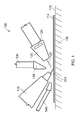
Figure 1 shows a schematic partial side view of a consolidation device according to a first embodiment of the present invention; -
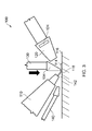
Figure 2 shows the consolidation device ofFigure 1 with a foot portion in a first, retracted position; -
Figure 3 shows the consolidation device ofFigure 1 with a foot portion in a second, extended position; and -
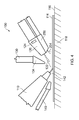
Figure 4 shows a schematic partial side view of a consolidation device according to a second embodiment of the present invention. - It is noted that the drawings may not be to scale. The drawings are intended to depict only typical aspects of the invention, and therefore should not be considered as limiting the scope of the invention. In the drawings, like numbering represents like elements between the drawings.
- Referring to
Figures 1 to 3 , a consolidation device according to a first embodiment of the invention is designated generally by thereference numeral 100. - The
consolidation device 100 comprises a dispensingassembly 110, afirst nozzle assembly 120, acompaction assembly 130 and asecond nozzle assembly 140. - The dispensing
assembly 110 is configured to dispense acomposite precursor material 114 onto asurface 116 of amould 118. Thecomposite precursor material 114 takes the form of a pre-pregcomposite tape 114. - In this embodiment, dispensing
assembly 110 is part of a conventional automated composite tape-laying machine (not shown). The dispensingassembly 110 is oriented at an acute angle to its direction of travel over thesurface 116. - The
first nozzle assembly 120 is positioned rearward of the dispensingassembly 110 and is oriented so as to direct afluid stream 122 onto the surface of thecomposite tape 114 as it is dispensed onto thesurface 116. Thegas stream 122 takes the form ofcompressed air flow 122. - A
heating element 124 is positioned within thefirst nozzle assembly 120 and is configured to controllably increase the temperature of thegas stream 122. The volumetric flow rate of thegas stream 122 exiting thefirst nozzle assembly 120 may also be controllably varied. In one arrangement, this volumetric flow rate ranges between 0.2 m3/sec and 0.7 m3/sec. - The
compaction assembly 130 comprises an actuator (not shown) and afoot portion 134, and is positioned between the dispensingassembly 110 and thefirst nozzle assembly 120. - As shown in
Figures 2 and3 , the actuator is configured to controllably move thefoot portion 134 in a direction of travel substantially normal to thesurface 116, between a first retracted position and a second extended position. In its first extended position, thefoot portion 134 presses against thesurface 116. - The
second nozzle assembly 140 is positioned between the dispensingassembly 110 and thesurface 116, and is connected to a vacuum source (not shown). Thesecond nozzle assembly 140 creates a partial vacuum in theregion 142 immediately forward of thecomposite tape 114 as it is dispensed onto thesurface 116. - The first and second nozzle assemblies 120,140 may be connected to an actuation system (not shown) to enable them to be independently positioned relative to the dispensing
assembly 110. The operation of this actuation system may be controlled in a pre-programmed manner or through a feedback system which is capable of altering the position of either nozzle assembly 120,140 as thetape 114 is being dispensed. This feature may enable the system to consolidate material in highly contoured regions of amould surface 116 where there is limited clearance for the dispensingassembly 110. This feature may also provide 'steerage' to thecomposite tape 114 to, for instance, even up the gaps between thetapes 114 when crossing acontoured surface 118. - In use, an end of the
composite tape 114 is positioned on thesurface 116 of themould 118. The dispensingassembly 110 remains stationary while thecompaction assembly 130 is actuated. This actuation causes thefoot portion 134 of thecompaction assembly 130 to extend and press the end of thecomposite tape 114 securely against thesurface 116. - At this point, the dispensing
assembly 110 moves over thesurface 116 over themould 118 in a pre-determined path and dispenses thecomposite tape 114 onto thesurface 116. - The
second nozzle assembly 140 creates a partial vacuum forward of thecomposite tape 114 as it is dispensed onto thesurface 116. This partial vacuum assists in thecomposite tape 114 adhering to thesurface 116 by minimising the amount of air which becomes trapped beneath thecomposite tape 114. - The
first nozzle assembly 120 directs acompressed air stream 122 onto an upper surface of thecomposite tape 114 as it is applied to thesurface 116. The pressure of thecompressed air stream 122 can be varied so as to provide a uniform compaction force over a contoured mould surface. Thecompressed air stream 122 forces any remaining trapped air from beneath the dispensed composite tape and consolidates the tape layers together. - When the dispensing assembly has dispensed the appropriate length of tape onto the
surface 116 it automatically cuts the tape, repositions itself at the start of the next tape placement route and feeds an end of the tape in readiness for the compaction assembly to attach this to thesurface 116. - Referring to
Figure 4 , a consolidation device according to a second embodiment of the invention is designated generally by the reference numeral 200. Features of the consolidation device 200 which correspond to those ofconsolidation device 100 have been given corresponding reference numerals for ease of reference. - The consolidation device 200 has a dispensing
assembly 110, afirst nozzle assembly 120, acompaction assembly 130 and asecond nozzle assembly 140. - In addition, the consolidation device 200 includes a
third nozzle assembly 250 which is positioned between thefirst nozzle assembly 120 and thesurface 116. - In use, the consolidation device 200 functions in the same way as described above for the
consolidation device 100, with the following addition. - As the
composite tape 114 is dispensed and consolidated onto thesurface 116 of themould 118, thethird nozzle 250 directs a coldfluid stream 254 onto thesurface 116 of the consolidatedcomposite tape 114. - The present invention may be embodied in other specific forms without departing from its spirit or essential characteristics. The described embodiments are to be considered in all respects only as illustrative and not restrictive. The scope of the invention is therefore indicated by the appended claims rather than by the foregoing description. All changes which come within the meaning and range of equivalency of the claims are to be embraced within their scope.
Claims (13)
- A consolidation device (100,200) comprising:a dispensing assembly (110) configured to dispense a composite precursor material (114) onto a surface (116) of a mould (118); anda first nozzle assembly (120) configured to direct a fluid stream (122) onto the free surface of the dispensed composite precursor material (114), to thereby consolidate the dispensed composite precursor material (114) onto the surface (116) of the mould (118).
- A consolidation device (100,200) as claimed in Claim 1, the first nozzle assembly (120) comprising a heating element (124), and whereby the fluid stream (122) passes over the heating element (124) before exiting the first nozzle assembly (120) to thereby increase the temperature of the fluid stream (122).
- A consolidation device (100,200) as claimed in Claim 2, wherein the temperature of the fluid stream (122) exiting the first nozzle assembly (120) is preferably between 40°C and 150°C.
- A consolidation device (100,200) as claimed in any one of Claims 1 to 3, wherein a volumetric flow rate of the fluid stream (122) exiting the first nozzle assembly (120) may be varied in a pre-determined manner as the dispensing assembly (110) dispenses the composite precursor material (114).
- A consolidation device (100,200) as claimed in any one of Claims 1 to 4, wherein the composite precursor material (114) is selected from the group comprising composite fibres, composite tows and composite tape.
- A consolidation device (100,200) as claimed in any one of Claims 1 to 5, further comprising a compaction assembly (130) having:an actuator; anda foot portion (134), the foot portion (134) being movable between a first retracted position and a second extended position, whereby in the first position the foot portion (134) is spaced apart from the surface (116) of the mould (118), and in the second position the foot portion (134) presses against the dispensed composite precursor material (114).
- A consolidation device (100,200) as claimed in Claim 6, wherein the actuator is selected from the group comprising pneumatic actuators, hydraulic actuators, mechanical actuators or electric actuators.
- A consolidation device (100,200) as claimed in any one of Claims 1 to 7, further comprising a second nozzle assembly (140) configured to create a partial vacuum in a region between the composite precursor material (114) and the surface of the mould (118), as the composite precursor material (114) is dispensed from the dispensing assembly (110).
- A method of using a consolidation device (100,200) comprising a dispensing assembly (110) and a first nozzle assembly (120), the method comprising the steps of:(i) dispensing a composite precursor material (114) from the dispensing assembly (110) in a pre-determined arrangement onto a surface (116) of a mould (118);(ii) generating a stream of fluid (122) having a pre-determined volumetric flow rate; and(iii) controllably directing the stream of fluid (122) from the first nozzle assembly (120) onto the free surface of the dispensed composite precursor material (114) to thereby consolidate the dispensed composite precursor material (114) onto the surface (116) of the mould (118).
- A method as claimed in Claim 9, wherein step (ii) comprises the additional step of:(ii)(a) heating the stream of fluid (122) to a pre-determined temperature.
- A method as claimed in Claim 9 or Claim 10, wherein the composite precursor material (114) is selected from the group comprising composite fibres, a composite tows and composite tape.
- A method as claimed in any one of Claims 9 to 11, the consolidation device (100,200) further comprising a compaction device (130) having an actuator and a foot portion (134), and wherein step (i) comprises the additional step of:(i)(a) controllably extending the foot portion (134) from a first retracted position in which the foot portion (134) is spaced apart from the surface (116) of the mould (118), to a second extended position in which the foot portion (134) presses against the dispensed composite precursor material (114).
- A method as claimed in any one of Claims 9 to 12, the consolidation device (100,200) further comprising a second nozzle assembly (140), and wherein step i comprises the additional initial step of:(iv) using the second nozzle assembly (140) to create a partial vacuum in the region between the composite precursor material (114) and the mould surface (116) as the composite precursor material (114) is dispensed onto the surface (116) of the mould (118).
Applications Claiming Priority (1)
| Application Number | Priority Date | Filing Date | Title |
|---|---|---|---|
| GBGB1201964.2A GB201201964D0 (en) | 2012-02-06 | 2012-02-06 | A consolidation device and method of using the same |
Publications (2)
| Publication Number | Publication Date |
|---|---|
| EP2623301A1 true EP2623301A1 (en) | 2013-08-07 |
| EP2623301B1 EP2623301B1 (en) | 2017-07-26 |
Family
ID=45896643
Family Applications (1)
| Application Number | Title | Priority Date | Filing Date |
|---|---|---|---|
| EP13152336.7A Not-in-force EP2623301B1 (en) | 2012-02-06 | 2013-01-23 | A consolidation device and method of using the same |
Country Status (3)
| Country | Link |
|---|---|
| US (1) | US9656449B2 (en) |
| EP (1) | EP2623301B1 (en) |
| GB (1) | GB201201964D0 (en) |
Cited By (1)
| Publication number | Priority date | Publication date | Assignee | Title |
|---|---|---|---|---|
| WO2017006099A1 (en) * | 2015-07-03 | 2017-01-12 | Composite Technology And Applications Limited | A method of manufacturing a composite component |
Citations (4)
| Publication number | Priority date | Publication date | Assignee | Title |
|---|---|---|---|---|
| DE3215930C1 (en) * | 1982-04-29 | 1983-05-19 | Messerschmitt-Bölkow-Blohm GmbH, 8000 München | Laminating device for fibre composites |
| DE3226290A1 (en) * | 1982-07-14 | 1984-01-26 | Messerschmitt-Bölkow-Blohm GmbH, 8000 München | Process and device for controlled lay-up of fibres on a mould |
| US20090130450A1 (en) * | 2007-11-17 | 2009-05-21 | The Boeing Company | Method and apparatus for placing plies on curved substrates |
| EP2345530A1 (en) * | 2010-01-15 | 2011-07-20 | KraussMaffei Technologies GmbH | Device and method for direct spraying of a fibre sheet |
Family Cites Families (4)
| Publication number | Priority date | Publication date | Assignee | Title |
|---|---|---|---|---|
| DE321590C (en) | 1913-02-22 | 1920-06-08 | Mallinson Powley | Machine for brushing and washing bottles, jugs and similar containers |
| US3825441A (en) * | 1968-09-27 | 1974-07-23 | Boise Cascade Corp | Method for impregnating corrugated cardboard,and resultant product |
| EP0644040A1 (en) | 1993-05-27 | 1995-03-22 | Cincinnati Milacron Inc. | Method of and apparatus for laying composite material |
| FR2727028B1 (en) | 1994-11-21 | 1997-01-24 | Salomon Sa | METHOD FOR MANUFACTURING A GLUE SKI COMPRISING A WET REINFORCEMENT REINFORCEMENT STAGE |
-
2012
- 2012-02-06 GB GBGB1201964.2A patent/GB201201964D0/en not_active Ceased
-
2013
- 2013-01-23 US US13/747,785 patent/US9656449B2/en active Active
- 2013-01-23 EP EP13152336.7A patent/EP2623301B1/en not_active Not-in-force
Patent Citations (4)
| Publication number | Priority date | Publication date | Assignee | Title |
|---|---|---|---|---|
| DE3215930C1 (en) * | 1982-04-29 | 1983-05-19 | Messerschmitt-Bölkow-Blohm GmbH, 8000 München | Laminating device for fibre composites |
| DE3226290A1 (en) * | 1982-07-14 | 1984-01-26 | Messerschmitt-Bölkow-Blohm GmbH, 8000 München | Process and device for controlled lay-up of fibres on a mould |
| US20090130450A1 (en) * | 2007-11-17 | 2009-05-21 | The Boeing Company | Method and apparatus for placing plies on curved substrates |
| EP2345530A1 (en) * | 2010-01-15 | 2011-07-20 | KraussMaffei Technologies GmbH | Device and method for direct spraying of a fibre sheet |
Cited By (5)
| Publication number | Priority date | Publication date | Assignee | Title |
|---|---|---|---|---|
| WO2017006099A1 (en) * | 2015-07-03 | 2017-01-12 | Composite Technology And Applications Limited | A method of manufacturing a composite component |
| CN107848225A (en) * | 2015-07-03 | 2018-03-27 | 复合材料技术和应用有限公司 | The method for manufacturing composite component |
| JP2018519197A (en) * | 2015-07-03 | 2018-07-19 | コンポジット テクノロジー アンド アプリケーションズ リミテッド | Manufacturing method of composite material |
| CN107848225B (en) * | 2015-07-03 | 2020-06-05 | 劳斯莱斯股份有限公司 | Method for producing a composite component |
| US11458654B2 (en) | 2015-07-03 | 2022-10-04 | Rolls-Royce Plc | Method of manufacturing a composite component |
Also Published As
| Publication number | Publication date |
|---|---|
| EP2623301B1 (en) | 2017-07-26 |
| US20130199721A1 (en) | 2013-08-08 |
| GB201201964D0 (en) | 2012-03-21 |
| US9656449B2 (en) | 2017-05-23 |
Similar Documents
| Publication | Publication Date | Title |
|---|---|---|
| CN106255584B (en) | Apparatus and method for forming a three-dimensional object | |
| CA2770383C (en) | Process and apparatus for producing beam member | |
| KR102534643B1 (en) | Systems and methods for additively manufacturing composite parts | |
| JP6475232B2 (en) | Fiber reinforced additive manufacturing method | |
| US11806923B2 (en) | System for additive manufacturing | |
| EP2227373B1 (en) | An apparatus and a method for preparing a pre-form | |
| CN114454478A (en) | System and method for controlling additive manufacturing | |
| CA3044125C (en) | Continuous fabrication for composite preforms | |
| WO2015118068A1 (en) | Tape-laying device and method for constructing a laminate | |
| WO2015118063A1 (en) | Tape-laying device and method for constructing a laminate | |
| AU2000265409A1 (en) | Method of placing fibers into channels of a mold and fiber placement head for accomplishing same | |
| WO2001096223A1 (en) | Method of placing fibers into channels of a mold and fiber placement head for accomplishing same | |
| US9656449B2 (en) | Consolidation device and method of using the same | |
| DE202014100515U1 (en) | Tape laying device for building a laminate | |
| DE202014100513U1 (en) | Tape laying device for building a laminate | |
| EP4000887B1 (en) | Method and apparatus for placing multi-lane tows | |
| DE202014100514U1 (en) | Tape laying device for building a laminate | |
| US11780181B2 (en) | Multi-lane tows for use with ply-by-ply forming machines | |
| WO2015118065A1 (en) | Tape-laying device and method for constructing a laminate |
Legal Events
| Date | Code | Title | Description |
|---|---|---|---|
| PUAI | Public reference made under article 153(3) epc to a published international application that has entered the european phase |
Free format text: ORIGINAL CODE: 0009012 |
|
| AK | Designated contracting states |
Kind code of ref document: A1 Designated state(s): AL AT BE BG CH CY CZ DE DK EE ES FI FR GB GR HR HU IE IS IT LI LT LU LV MC MK MT NL NO PL PT RO RS SE SI SK SM TR |
|
| AX | Request for extension of the european patent |
Extension state: BA ME |
|
| 17P | Request for examination filed |
Effective date: 20140205 |
|
| RBV | Designated contracting states (corrected) |
Designated state(s): AL AT BE BG CH CY CZ DE DK EE ES FI FR GB GR HR HU IE IS IT LI LT LU LV MC MK MT NL NO PL PT RO RS SE SI SK SM TR |
|
| 17Q | First examination report despatched |
Effective date: 20140325 |
|
| RAP1 | Party data changed (applicant data changed or rights of an application transferred) |
Owner name: ROLLS-ROYCE PLC |
|
| GRAP | Despatch of communication of intention to grant a patent |
Free format text: ORIGINAL CODE: EPIDOSNIGR1 |
|
| STAA | Information on the status of an ep patent application or granted ep patent |
Free format text: STATUS: GRANT OF PATENT IS INTENDED |
|
| INTG | Intention to grant announced |
Effective date: 20170517 |
|
| GRAS | Grant fee paid |
Free format text: ORIGINAL CODE: EPIDOSNIGR3 |
|
| GRAA | (expected) grant |
Free format text: ORIGINAL CODE: 0009210 |
|
| STAA | Information on the status of an ep patent application or granted ep patent |
Free format text: STATUS: THE PATENT HAS BEEN GRANTED |
|
| AK | Designated contracting states |
Kind code of ref document: B1 Designated state(s): AL AT BE BG CH CY CZ DE DK EE ES FI FR GB GR HR HU IE IS IT LI LT LU LV MC MK MT NL NO PL PT RO RS SE SI SK SM TR |
|
| REG | Reference to a national code |
Ref country code: GB Ref legal event code: FG4D |
|
| REG | Reference to a national code |
Ref country code: CH Ref legal event code: EP |
|
| REG | Reference to a national code |
Ref country code: AT Ref legal event code: REF Ref document number: 912022 Country of ref document: AT Kind code of ref document: T Effective date: 20170815 |
|
| REG | Reference to a national code |
Ref country code: IE Ref legal event code: FG4D |
|
| REG | Reference to a national code |
Ref country code: DE Ref legal event code: R096 Ref document number: 602013023933 Country of ref document: DE |
|
| REG | Reference to a national code |
Ref country code: NL Ref legal event code: MP Effective date: 20170726 |
|
| REG | Reference to a national code |
Ref country code: LT Ref legal event code: MG4D |
|
| REG | Reference to a national code |
Ref country code: AT Ref legal event code: MK05 Ref document number: 912022 Country of ref document: AT Kind code of ref document: T Effective date: 20170726 |
|
| REG | Reference to a national code |
Ref country code: FR Ref legal event code: PLFP Year of fee payment: 6 |
|
| PG25 | Lapsed in a contracting state [announced via postgrant information from national office to epo] |
Ref country code: FI Free format text: LAPSE BECAUSE OF FAILURE TO SUBMIT A TRANSLATION OF THE DESCRIPTION OR TO PAY THE FEE WITHIN THE PRESCRIBED TIME-LIMIT Effective date: 20170726 Ref country code: AT Free format text: LAPSE BECAUSE OF FAILURE TO SUBMIT A TRANSLATION OF THE DESCRIPTION OR TO PAY THE FEE WITHIN THE PRESCRIBED TIME-LIMIT Effective date: 20170726 Ref country code: LT Free format text: LAPSE BECAUSE OF FAILURE TO SUBMIT A TRANSLATION OF THE DESCRIPTION OR TO PAY THE FEE WITHIN THE PRESCRIBED TIME-LIMIT Effective date: 20170726 Ref country code: SE Free format text: LAPSE BECAUSE OF FAILURE TO SUBMIT A TRANSLATION OF THE DESCRIPTION OR TO PAY THE FEE WITHIN THE PRESCRIBED TIME-LIMIT Effective date: 20170726 Ref country code: HR Free format text: LAPSE BECAUSE OF FAILURE TO SUBMIT A TRANSLATION OF THE DESCRIPTION OR TO PAY THE FEE WITHIN THE PRESCRIBED TIME-LIMIT Effective date: 20170726 Ref country code: NL Free format text: LAPSE BECAUSE OF FAILURE TO SUBMIT A TRANSLATION OF THE DESCRIPTION OR TO PAY THE FEE WITHIN THE PRESCRIBED TIME-LIMIT Effective date: 20170726 Ref country code: NO Free format text: LAPSE BECAUSE OF FAILURE TO SUBMIT A TRANSLATION OF THE DESCRIPTION OR TO PAY THE FEE WITHIN THE PRESCRIBED TIME-LIMIT Effective date: 20171026 |
|
| PG25 | Lapsed in a contracting state [announced via postgrant information from national office to epo] |
Ref country code: BG Free format text: LAPSE BECAUSE OF FAILURE TO SUBMIT A TRANSLATION OF THE DESCRIPTION OR TO PAY THE FEE WITHIN THE PRESCRIBED TIME-LIMIT Effective date: 20171026 Ref country code: RS Free format text: LAPSE BECAUSE OF FAILURE TO SUBMIT A TRANSLATION OF THE DESCRIPTION OR TO PAY THE FEE WITHIN THE PRESCRIBED TIME-LIMIT Effective date: 20170726 Ref country code: PL Free format text: LAPSE BECAUSE OF FAILURE TO SUBMIT A TRANSLATION OF THE DESCRIPTION OR TO PAY THE FEE WITHIN THE PRESCRIBED TIME-LIMIT Effective date: 20170726 Ref country code: IS Free format text: LAPSE BECAUSE OF FAILURE TO SUBMIT A TRANSLATION OF THE DESCRIPTION OR TO PAY THE FEE WITHIN THE PRESCRIBED TIME-LIMIT Effective date: 20171126 Ref country code: LV Free format text: LAPSE BECAUSE OF FAILURE TO SUBMIT A TRANSLATION OF THE DESCRIPTION OR TO PAY THE FEE WITHIN THE PRESCRIBED TIME-LIMIT Effective date: 20170726 Ref country code: GR Free format text: LAPSE BECAUSE OF FAILURE TO SUBMIT A TRANSLATION OF THE DESCRIPTION OR TO PAY THE FEE WITHIN THE PRESCRIBED TIME-LIMIT Effective date: 20171027 Ref country code: ES Free format text: LAPSE BECAUSE OF FAILURE TO SUBMIT A TRANSLATION OF THE DESCRIPTION OR TO PAY THE FEE WITHIN THE PRESCRIBED TIME-LIMIT Effective date: 20170726 |
|
| PG25 | Lapsed in a contracting state [announced via postgrant information from national office to epo] |
Ref country code: CZ Free format text: LAPSE BECAUSE OF FAILURE TO SUBMIT A TRANSLATION OF THE DESCRIPTION OR TO PAY THE FEE WITHIN THE PRESCRIBED TIME-LIMIT Effective date: 20170726 Ref country code: RO Free format text: LAPSE BECAUSE OF FAILURE TO SUBMIT A TRANSLATION OF THE DESCRIPTION OR TO PAY THE FEE WITHIN THE PRESCRIBED TIME-LIMIT Effective date: 20170726 Ref country code: DK Free format text: LAPSE BECAUSE OF FAILURE TO SUBMIT A TRANSLATION OF THE DESCRIPTION OR TO PAY THE FEE WITHIN THE PRESCRIBED TIME-LIMIT Effective date: 20170726 |
|
| REG | Reference to a national code |
Ref country code: DE Ref legal event code: R097 Ref document number: 602013023933 Country of ref document: DE |
|
| PG25 | Lapsed in a contracting state [announced via postgrant information from national office to epo] |
Ref country code: EE Free format text: LAPSE BECAUSE OF FAILURE TO SUBMIT A TRANSLATION OF THE DESCRIPTION OR TO PAY THE FEE WITHIN THE PRESCRIBED TIME-LIMIT Effective date: 20170726 Ref country code: IT Free format text: LAPSE BECAUSE OF FAILURE TO SUBMIT A TRANSLATION OF THE DESCRIPTION OR TO PAY THE FEE WITHIN THE PRESCRIBED TIME-LIMIT Effective date: 20170726 Ref country code: SM Free format text: LAPSE BECAUSE OF FAILURE TO SUBMIT A TRANSLATION OF THE DESCRIPTION OR TO PAY THE FEE WITHIN THE PRESCRIBED TIME-LIMIT Effective date: 20170726 Ref country code: SK Free format text: LAPSE BECAUSE OF FAILURE TO SUBMIT A TRANSLATION OF THE DESCRIPTION OR TO PAY THE FEE WITHIN THE PRESCRIBED TIME-LIMIT Effective date: 20170726 |
|
| PLBE | No opposition filed within time limit |
Free format text: ORIGINAL CODE: 0009261 |
|
| STAA | Information on the status of an ep patent application or granted ep patent |
Free format text: STATUS: NO OPPOSITION FILED WITHIN TIME LIMIT |
|
| 26N | No opposition filed |
Effective date: 20180430 |
|
| PG25 | Lapsed in a contracting state [announced via postgrant information from national office to epo] |
Ref country code: SI Free format text: LAPSE BECAUSE OF FAILURE TO SUBMIT A TRANSLATION OF THE DESCRIPTION OR TO PAY THE FEE WITHIN THE PRESCRIBED TIME-LIMIT Effective date: 20170726 |
|
| REG | Reference to a national code |
Ref country code: CH Ref legal event code: PL |
|
| PG25 | Lapsed in a contracting state [announced via postgrant information from national office to epo] |
Ref country code: LU Free format text: LAPSE BECAUSE OF NON-PAYMENT OF DUE FEES Effective date: 20180123 |
|
| REG | Reference to a national code |
Ref country code: IE Ref legal event code: MM4A |
|
| REG | Reference to a national code |
Ref country code: BE Ref legal event code: MM Effective date: 20180131 |
|
| PG25 | Lapsed in a contracting state [announced via postgrant information from national office to epo] |
Ref country code: LI Free format text: LAPSE BECAUSE OF NON-PAYMENT OF DUE FEES Effective date: 20180131 Ref country code: CH Free format text: LAPSE BECAUSE OF NON-PAYMENT OF DUE FEES Effective date: 20180131 Ref country code: BE Free format text: LAPSE BECAUSE OF NON-PAYMENT OF DUE FEES Effective date: 20180131 |
|
| PG25 | Lapsed in a contracting state [announced via postgrant information from national office to epo] |
Ref country code: IE Free format text: LAPSE BECAUSE OF NON-PAYMENT OF DUE FEES Effective date: 20180123 |
|
| PG25 | Lapsed in a contracting state [announced via postgrant information from national office to epo] |
Ref country code: MC Free format text: LAPSE BECAUSE OF FAILURE TO SUBMIT A TRANSLATION OF THE DESCRIPTION OR TO PAY THE FEE WITHIN THE PRESCRIBED TIME-LIMIT Effective date: 20170726 |
|
| PG25 | Lapsed in a contracting state [announced via postgrant information from national office to epo] |
Ref country code: MT Free format text: LAPSE BECAUSE OF NON-PAYMENT OF DUE FEES Effective date: 20180123 |
|
| PG25 | Lapsed in a contracting state [announced via postgrant information from national office to epo] |
Ref country code: TR Free format text: LAPSE BECAUSE OF FAILURE TO SUBMIT A TRANSLATION OF THE DESCRIPTION OR TO PAY THE FEE WITHIN THE PRESCRIBED TIME-LIMIT Effective date: 20170726 |
|
| PG25 | Lapsed in a contracting state [announced via postgrant information from national office to epo] |
Ref country code: HU Free format text: LAPSE BECAUSE OF FAILURE TO SUBMIT A TRANSLATION OF THE DESCRIPTION OR TO PAY THE FEE WITHIN THE PRESCRIBED TIME-LIMIT; INVALID AB INITIO Effective date: 20130123 Ref country code: PT Free format text: LAPSE BECAUSE OF FAILURE TO SUBMIT A TRANSLATION OF THE DESCRIPTION OR TO PAY THE FEE WITHIN THE PRESCRIBED TIME-LIMIT Effective date: 20170726 |
|
| PG25 | Lapsed in a contracting state [announced via postgrant information from national office to epo] |
Ref country code: CY Free format text: LAPSE BECAUSE OF FAILURE TO SUBMIT A TRANSLATION OF THE DESCRIPTION OR TO PAY THE FEE WITHIN THE PRESCRIBED TIME-LIMIT Effective date: 20170726 Ref country code: MK Free format text: LAPSE BECAUSE OF NON-PAYMENT OF DUE FEES Effective date: 20170726 |
|
| PG25 | Lapsed in a contracting state [announced via postgrant information from national office to epo] |
Ref country code: AL Free format text: LAPSE BECAUSE OF FAILURE TO SUBMIT A TRANSLATION OF THE DESCRIPTION OR TO PAY THE FEE WITHIN THE PRESCRIBED TIME-LIMIT Effective date: 20170726 |
|
| PGFP | Annual fee paid to national office [announced via postgrant information from national office to epo] |
Ref country code: GB Payment date: 20220118 Year of fee payment: 10 Ref country code: DE Payment date: 20220127 Year of fee payment: 10 |
|
| PGFP | Annual fee paid to national office [announced via postgrant information from national office to epo] |
Ref country code: FR Payment date: 20220126 Year of fee payment: 10 |
|
| REG | Reference to a national code |
Ref country code: DE Ref legal event code: R119 Ref document number: 602013023933 Country of ref document: DE |
|
| GBPC | Gb: european patent ceased through non-payment of renewal fee |
Effective date: 20230123 |
|
| PG25 | Lapsed in a contracting state [announced via postgrant information from national office to epo] |
Ref country code: GB Free format text: LAPSE BECAUSE OF NON-PAYMENT OF DUE FEES Effective date: 20230123 Ref country code: DE Free format text: LAPSE BECAUSE OF NON-PAYMENT OF DUE FEES Effective date: 20230801 |
|
| PG25 | Lapsed in a contracting state [announced via postgrant information from national office to epo] |
Ref country code: FR Free format text: LAPSE BECAUSE OF NON-PAYMENT OF DUE FEES Effective date: 20230131 |