EP2623063A1 - Surgical instrument and surgery support system having said surgical instrument - Google Patents
Surgical instrument and surgery support system having said surgical instrument Download PDFInfo
- Publication number
- EP2623063A1 EP2623063A1 EP11844452.0A EP11844452A EP2623063A1 EP 2623063 A1 EP2623063 A1 EP 2623063A1 EP 11844452 A EP11844452 A EP 11844452A EP 2623063 A1 EP2623063 A1 EP 2623063A1
- Authority
- EP
- European Patent Office
- Prior art keywords
- surgical instrument
- distal end
- unit
- instrument distal
- driving
- Prior art date
- Legal status (The legal status is an assumption and is not a legal conclusion. Google has not performed a legal analysis and makes no representation as to the accuracy of the status listed.)
- Granted
Links
Images



Classifications
-
- A—HUMAN NECESSITIES
- A61—MEDICAL OR VETERINARY SCIENCE; HYGIENE
- A61B—DIAGNOSIS; SURGERY; IDENTIFICATION
- A61B34/00—Computer-aided surgery; Manipulators or robots specially adapted for use in surgery
- A61B34/30—Surgical robots
-
- A—HUMAN NECESSITIES
- A61—MEDICAL OR VETERINARY SCIENCE; HYGIENE
- A61B—DIAGNOSIS; SURGERY; IDENTIFICATION
- A61B34/00—Computer-aided surgery; Manipulators or robots specially adapted for use in surgery
- A61B34/30—Surgical robots
- A61B34/37—Leader-follower robots
-
- A—HUMAN NECESSITIES
- A61—MEDICAL OR VETERINARY SCIENCE; HYGIENE
- A61B—DIAGNOSIS; SURGERY; IDENTIFICATION
- A61B90/00—Instruments, implements or accessories specially adapted for surgery or diagnosis and not covered by any of the groups A61B1/00 - A61B50/00, e.g. for luxation treatment or for protecting wound edges
- A61B90/08—Accessories or related features not otherwise provided for
- A61B2090/0803—Counting the number of times an instrument is used
Definitions
- the present invention relates to a surgical instrument and an operation support system having such a surgical instrument.
- Jpn. Pat. Appln. KOKAI Publication No. 2000-107189 has suggested a technique for using a surgical instrument within its life.
- the surgical instrument has an internal battery so that the internal battery discharges electricity while the surgical instrument is attached to an arm.
- the electromotive force of the internal battery is measured to measure, as the life of the surgical instrument, the time in which the surgical instrument is attached to the arm.
- the electromotive force of the internal battery is equal to or less than a predetermined value, an alarm for encouraging the replacement of the surgical instrument is given.
- the present invention has been made in consideration of the above circumstances, and is intended to provide a surgical instrument capable of accurately controlling the life of the surgical instrument and an operation support system having the surgical instrument.
- a surgical instrument comprising: a use measurement unit configured to acquire a use time or an operation amount of the surgical instrument in response to the use or operation of the surgical instrument.
- an operation support system comprising: the surgical instrument according to the first aspect; and an arm to which the surgical instrument is attached.
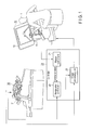
- FIG. 1 is a diagram showing the overall configuration of a master-slave manipulator as an example of an operation support system according to embodiments of the present invention.
- the master-slave manipulator according to the present embodiments comprises a remote operation device 10, a controller 20, and a slave manipulator 30.
- the operation unit 11 comprises, for example, driving shafts and a gripper.
- An operator 1 operates the operation unit 11 so that the driving shafts constituting the operation unit 11 are driven.
- the driving amount of each driving shaft is detected by an unshown position sensor (e.g., an encoder) provided in each driving shaft.
- a detection signal of each position sensor is output to the controller 20 as a signal (operation signal) that indicates operation information for the operation unit 11 to give a command regarding the position and orientation of the end of a slave arm 31 of the slave manipulator 30.
- the display unit 12 comprises, for example, a liquid crystal display, and displays an image in accordance with an image signal input from the controller 20.
- the image signal input from the controller 20 is provided by processing, in the controller 20, an image signal which is obtained via an electronic camera (electronic endoscope) attached to the slave arm 31.
- the image based on such an image signal is displayed on the display unit 12 so that the operator 1 of the remote operation device 10 can check an image of the end of the slave manipulator 30 located apart from the remote operation device 10.
- the controller 20 comprises a master control unit 21, a manipulator control unit 22, and an image processing unit 23.
- the manipulator control unit 22 calculates, for example, by inverse-kinematic computation, a desired driving amount of each joint of the slave arm 31 necessary for the position and orientation of the end of the slave arm 31 to correspond to the command values.
- the image processing unit 23 processes the image signal obtained from the electronic camera (e.g., electronic endoscope) provided at the end of the slave arm 31, and generates an image signal to be displayed on the display unit 12, and then outputs the image signal to the display unit 12.
- the electronic camera e.g., electronic endoscope
- the slave manipulator 30 has the slave arm 31.
- the slave arm 31 comprises a positioning arm and a surgical instrument.
- the positioning arm has multiple joints, and is configured so that each joint is driven in accordance with a control signal from the manipulator control unit 22.
- the surgical instrument comprises a surgical instrument distal end, and a driving unit for driving the surgical instrument distal end.
- the surgical instrument distal end is attached to the distal end of the positioning arm, and the driving unit is provided in the positioning arm.
- a gripper for example, is used as the surgical instrument.
- a camera electronic endoscope
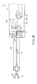
- the slave arm 31 according to the present embodiments is further described with reference to FIG. 2A and FIG. 2B .
- the slave arm 31 comprises a positioning arm 100 and a surgical instrument distal end 200.
- An attachment portion for attaching the surgical instrument distal end 200 is formed at the distal end of the positioning arm 100.
- the attachment portion is provided with a driving mechanism 101 which is a driving unit for driving the surgical instrument distal end 200, and an electricity supply unit 111 for supplying electricity to a timer 201 provided in the surgical instrument distal end 200.
- the driving mechanism 101 comprises an actuator unit 102, a power transmission unit 103, and a driving amount detecting unit 104.
- the actuator unit 102 is a mechanism for generating input to drive the surgical instrument distal end 200, and comprises, for example, a motor.
- the actuator unit 102 generates input to drive the surgical instrument distal end 200 in accordance with a control signal from the manipulator control unit 22.
- the power transmission unit 103 is a mechanism for transmitting the input generated by, for example, the motor to the surgical instrument distal end 200.
- the power transmission unit 103 illustrated in FIG. 2A is a mechanism that uses gears and a belt to transmit the rotating input generated in the actuator unit 102 to the surgical instrument distal end 200.
- the configurations of the actuator unit 102 and the power transmission unit 103 shown in FIG. 2A are illustrative only, and can be suitably modified.
- the driving amount detecting unit 104 comprises, for example, an encoder, and detects the driving amount (rotation amount in the example of FIG. 2A ) of the actuator unit 102 as an electric signal.
- the electricity supply unit 111 is conductively connected to the timer 201 in the surgical instrument distal end 200 when the surgical instrument distal end 200 is attached to the positioning arm 100.
- the electricity supply unit 111 is connected to the timer 201, for example, by a connector.
- the electricity supply unit 111 having such a configuration supplies electricity for driving the timer 201.
- the surgical instrument distal end 200 comprises the timer 201, a power transmission unit 202, and a distal movable portion 203.
- the timer 201 as an example of a use measurement unit is a timer for performing a countdown when supplied with electricity from the electricity supply unit 111.
- the time counted by the timer 201 corresponds to the available time (life) of the surgical instrument distal end 200.
- the timer 201 may be an analog timer that uses a mechanical structure such as a spring for counting, or may be a digital timer such as a digital counter.
- the timer 201 according to the present embodiments is provided with a lock mechanism 201a.
- the lock mechanism 201a is actuated and locks the operation of the power transmission unit 202 when the timer 201 counts "0", that is, when the life of the surgical instrument distal end 200 has expired.
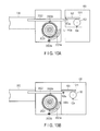
- the lock mechanism 201a may use, for example, a lock member to mechanically lock the operation of the power transmission unit 202, or may use, for example, a relay to electrically lock the operation of the power transmission unit 202. For example, in the example shown in FIG. 4 , the operation of the actuator unit is mechanically locked.
- the power transmission unit 202 is configured to contact the power transmission unit 103 of the positioning arm 100 when the surgical instrument distal end 200 is attached to the distal end of the positioning arm 100.
- the power transmission unit 202 having such a configuration operates in response to the operation of the power transmission unit 103, and operates the distal movable portion 203 of the surgical instrument distal end 200.
- the power transmission unit 202 shown in the example of FIG. 2A operates the distal movable portion 203 by a rack-and-pinion mechanism which operates in association with the rotation of the gear of the power transmission unit 103.
- teeth of a pinion gear are not circumferentially formed, and are formed in a part corresponding to the movable range of the distal movable portion 203.
- the distal movable portion 203 is provided at the distal end of the surgical instrument distal end 200, and operates in response to the operation of the power transmission unit 202.
- a gripper which opens and shuts in response to the back-and-forth motion of a rack that constitutes the power transmission unit 202 is provided as the distal movable portion 203.
- the gear of the power transmission unit 103 is engaged with the pinion gear of the power transmission unit 202, and the distal movable portion 203 operates in accordance with the input generated in the actuator unit 102.
- the pinion gear of the power transmission unit 202 is rotated in a direction B accordingly.
- the rack of the power transmission unit 202 moves in a direction C to pull the distal movable portion 203.
- the distal movable portion 203 is shut as indicated by a direction D.
- the motor that constitutes the actuator unit 102 is rotated in the opposite direction, the distal movable portion 203 is opened.
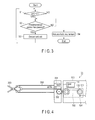
- FIG. 3 is a flowchart showing the operation of the timer 201. The operation shown in FIG. 3 is performed while electricity is being supplied to the timer 201 by the electricity supply unit 111. When the supply of the electricity to the timer 201 from the electricity supply unit 111 is stopped, the operation shown in FIG. 3 is ended.
- a predetermined number of use is set for a count cnt as an initial value.
- step S1 whether the count cnt of the timer 201 is beyond 0 is determined.
- step S2 determines whether the count cnt is beyond 0 in step S1 and whether a predetermined period has passed.
- step S3 the count cnt is decremented (countdown) (step S3).
- the processing then returns to step S1. That is, the countdown is continued until the count cnt reaches 0.
- step S1 When the count cnt is 0 in step S1, that is, when the surgical instrument distal end 200 has no remaining life, the operation of the surgical instrument distal end 200 is locked by the lock mechanism 201a, for example, as shown in FIG. 4 (step S4).
- the operation shown in FIG. 3 includes judging whether the count cnt is beyond 0. For an analog timer that uses a mechanical structure such as a spring for counting, there is no such a judgment, and the locking operation in step S4 is performed when the count cnt has reached 0.
- FIG. 5 is a flowchart showing the operation of the manipulator control unit 22.
- the manipulator control unit 22 determines whether a command value conforming to the operation of the operation unit 11 by the operator 1 is input from the master control unit 21 (step S11). When it is determined in step S11 that no command value is input, the manipulator control unit 22 performs the judgment in step S11 and waits until the command value is input. When it is determined in step S11 that a command value is input, the manipulator control unit 22 calculates, for example, by inverse-kinematic computation, a desired driving amount of the actuator unit 102 to drive each joint of the positioning arm 100 in accordance with an input command value (step S12). For the inverse-kinematic computation, various known methods such as an analytical technique can be used. The details are not described here.
- the manipulator control unit 22 determines whether the difference between the calculated driving amount and the driving amount detecting unit 104 is equal to or less than a predetermined value (step S13).
- the lock mechanism 201a is actuated, and the operation of the surgical instrument distal end 200 is locked.
- the operation of the actuator unit 102 is also locked. Therefore, the detection value of the driving amount detecting unit 104 does not change.
- the driving amount of the actuator unit 102 calculated in step S12 constantly changes depending on the operation of the operation unit 11 by the operator 1.
- the difference between the driving amount of the actuator unit 102 and the detection value of the driving amount detecting unit 104 can be obtained to determine whether the operation of the actuator unit 102 is stopped, that is, whether the surgical instrument distal end 200 has a remaining life.
- step S13 When it is determined in step S13 that the difference between the calculated desired driving amount and the detection value of the driving amount detecting unit 104 is equal to or less than the predetermined value, this means that the actuator unit 102 operates in accordance with the driving amount calculated in the manipulator control unit 22, in other words, the surgical instrument distal end 200 has a remaining life.
- the manipulator control unit 22 inputs the calculated desired driving amount to the actuator unit 102 of the positioning arm 100 to operate the surgical instrument distal end 200 (step S14).
- the difference between the calculated driving amount and the detection value of the driving amount detecting unit 104 is beyond the predetermined value, this means that the operation of the surgical instrument distal end 200 is locked, in other words, the surgical instrument distal end 200 has no remaining life.
- the manipulator control unit 22 sends an instruction to the image processing unit 23 to display, on the display unit 12, an alarm display for encouraging the replacement of the surgical instrument distal end 200 (step S15).
- the manipulator control unit 22 then ends the operation shown in FIG. 5 .
- the alarm display is shown here by way of example, the alarm display is not the exclusive means for encouraging the replacement of the surgical instrument distal end 200.
- the surgical instrument distal end 200 has the timer 201 therein. While the surgical instrument distal end 200 is attached to the positioning arm 100 and electricity is being supplied to the timer 201, the timer 201 performs a countdown. When the timer 201 counts 0, the operation of the surgical instrument distal end 200 is locked. Thus, the time in which the surgical instrument distal end 200 is attached to the positioning arm 100 is correctly measured in the surgical instrument distal end 200 as the life of the surgical instrument distal end 200. When the surgical instrument distal end 200 has come to the end of its life, the operation of the surgical instrument distal end 200 can be instantaneously locked.
- the manipulator control unit 22 can determine by the detection value from the driving amount detecting unit 104 whether the surgical instrument distal end 200 has a remaining life. In accordance with this determination, the manipulator control unit 22 can give an alarm for encouraging the replacement of the surgical instrument distal end 200 to the operator 1. Thus, the surgical instrument distal end 200 and the manipulator control unit 22 do not need to be conductively connected.
- the timer 201 performs a countdown while electricity is being supplied to the timer 201. Otherwise, the timer 201 may perform a countdown when the surgical instrument distal end 200 is attached to the positioning arm 100. In this case, the number of times the surgical instrument distal end 200 is attached to the positioning arm 100 can be measured as the life of the surgical instrument distal end 200.
- the second embodiment of the present invention is described.
- the time in which the surgical instrument distal end 200 is attached to the positioning arm 100 is measured as the life of the surgical instrument distal end 200.
- the number of times or the time in which the surgical instrument distal end 200 is actually used (operated) is measured as the life of the surgical instrument distal end 200.
- FIG. 6 is a diagram showing the configuration of a slave arm 31 according to the second embodiment of the present invention.
- the slave arm 31 shown in FIG. 6 also comprises a positioning arm 100 and a surgical instrument distal end 200. Components similar to those in FIG. 2A are provided with the same reference signs similar to those in FIG. 2A and are not described below.
- An electricity supply unit 111 in FIG. 6 is conductively connected to a counter IC 201 in the surgical instrument distal end 200 when the surgical instrument distal end 200 is attached to the positioning arm 100.
- the electricity supply unit 111 having such a configuration supplies electricity for driving the counter IC 201.
- the electricity supply unit 111 according to the present embodiment is provided with a terminal (signal) for receiving a surgical instrument replacement request signal from the counter IC 201, in addition to terminals (V, Gnd) for supplying electricity to drive the counter IC 201.
- the surgical instrument replacement request signal will be described later.
- the power transmission unit 202 shown by way of example in the second embodiment operates a distal movable portion 203 by a rack-and-pinion mechanism.
- a protrusion 2021 is formed in a toothless part of a pinion gear that constitutes the power transmission unit 202.
- a switch (SW) 201b is further provided in the vicinity of the protrusion 2021. The SW 201b is turned on by being depressed when the protrusion 2021 formed in the pinion gear comes into contact with the SW 201b by the rotation of the pinion gear that constitutes the power transmission unit 202.
- the SW 201b is turned off when the protrusion 2021 formed in the pinion gear comes out of contact with the SW 201b by the rotation of the pinion gear that constitutes the power transmission unit 202.
- a count signal indicating that the SW 201b is turned on is input to the counter IC 201 from the SW 201b.
- the counter IC 201 as an example of a use measurement unit is an IC circuit for, for example, counting the count signals to measure the number of times the SW 201b is depressed. In this way, the number of times the power transmission unit 202 is operated, that is, the number of times the surgical instrument distal end 200 is actually used can be measured by counting the count signals.
- the counter IC 201 also performs processing to lock the operation of the surgical instrument distal end 200 when the number of the count signals has reached a predetermined value. This processing may include, for example, forcibly driving the pinion gear to disengage a gear of a power transmission unit 103 and the pinion gear of the power transmission unit 202 so that the toothless part of the pinion gear faces the gear of the power transmission unit 202. That is, this processing corresponds to the mechanism for locking.
- FIG. 7 is a flowchart showing the operation of the counter IC 201. As in the first embodiment, the operation shown in FIG. 7 is performed while electricity is being supplied to the counter IC 201 by the electricity supply unit 111. When the supply of the electricity to the counter IC 201 from the electricity supply unit 111 is stopped, the operation shown in FIG. 7 is ended.
- the counter IC 201 determines by the presence of a count signal whether the SW 201b is depressed (step S21). When the SW 201b is depressed in step S21, the counter IC 201 increments (counts up) a count SW_cnt (step S22). On the other hand, when the SW 201b is not depressed in step S21, the counter IC 201 does not count up.
- the counter IC 201 compares the count SW_cnt with a predetermined value stored in a memory within the counter IC, and determines whether the count SW_cnt is equal to or less than the predetermined value as a result of the comparison (step S23).
- This predetermined value is the number corresponding to the life of the surgical instrument distal end 200.
- the counter IC 201 recognizes that the surgical instrument distal end 200 has no remaining life, and the counter IC 201 turns on a surgical instrument use end flag held in a register within the counter IC 201 (step S24).
- the counter IC 201 recognizes that the surgical instrument distal end 200 has no remaining life, and the counter IC 201 keeps off the surgical instrument use end flag held in the register within the counter IC 201.
- the counter IC 201 determines whether the surgical instrument use end flag is on (step S25). When the surgical instrument use end flag is off in step S25, that is, when the surgical instrument still has a remaining life, the processing returns to step S21. While the surgical instrument use end flag is off, the operations in step S21 to S25 are repeated. When the surgical instrument use end flag is on in step S25, that is, when the surgical instrument has no remaining life, the counter IC 201 locks the operation of the surgical instrument distal end 200, for example, by forcibly actuating the pinion gear (step S26). The counter IC 201 then outputs a surgical instrument replacement request signal to the electricity supply unit 111 (step S27). Further, the counter IC 201 ends the operation shown in FIG. 7 .
- the surgical instrument replacement request signal input to the electricity supply unit 111 is input to the manipulator control unit 22 having a function as an example of a reading unit.
- the manipulator control unit 22 sends an instruction to the image processing unit 23 to display, on the display unit 12, an alarm display for encouraging the replacement of the surgical instrument distal end 200, as in the processing in step S15 in FIG. 5 .
- the number of times the surgical instrument distal end 200 is actually operated is measured. Therefore, as compared with the first embodiment, the life of the surgical instrument distal end 200 is more correctly measured, and the operation of the surgical instrument distal end 200 can be instantaneously locked when the surgical instrument distal end 200 has come to the end of its life.
- the number of times the surgical instrument distal end 200 is actually operated is measured as an operation amount. Otherwise, the operating time of the surgical instrument distal end 200 may be measured as an operation amount.
- the counter IC 201 is used for measurement in the example described above, a mechanical counter may be used for measurement as in the first embodiment.
- the driving mechanism of the positioning arm 100 drives the surgical instrument distal end 200 by rotational input.
- the internal configuration of the positioning arm 100 is not particularly limited.
- the driving mechanism of the positioning arm 100 may drive the surgical instrument distal end 200 by translation input.
- FIG. 8 shows an example of the application of the configuration according to the second embodiment in which the driving mechanism of the positioning arm 100 has a translation mechanism.
- a rod 2022 that constitutes the power transmission unit 202 of the surgical instrument distal end 200 also performs translation motion.
- a protrusion 2022a similar to that described in the second embodiment is provided in the rod 2022, and an SW 201b and a counter IC 201 similar to those described in the second embodiment are provided in the vicinity of the protrusion 2022a.
- the driving mechanism of the positioning arm 100 has the translation mechanism in the application of the configuration according to the second embodiment shown here in FIG. 8
- the configuration according to the first embodiment may be applied instead.
- the distal movable portion 203 of the surgical instrument distal end 200 comprises one movable portion (gripper). Otherwise, as shown in FIG. 9 , the configurations according to the embodiments described above are also applicable when the distal movable portion of the surgical instrument distal end 200 comprises multiple movable portions.
- the distal movable portion comprises a gripper 203a and a joint 203b. The gripper 203a and the joint 203b are then driven by different power transmission units 202a and 202b via driving mechanisms 101a and 101b, respectively.
- FIG. 9 the distal movable portion comprises a gripper 203a and a joint 203b.
- the power transmission unit 202a drives the gripper 203a by pushing/drawing operation of a wire using a pulley
- the power transmission unit 202b drives the joint 203b by a rotational input transmission mechanism having a configuration substantially similar to those in the first and second embodiments.
- a timer 201 similar in configuration to that described in the first embodiment is provided in the vicinity of the power transmission unit 202b. In the same manner as described in the first embodiment, this timer 201 performs a countdown while the surgical instrument distal end 200 is attached to the positioning arm 100.
- the timer 201 locks the operation of the surgical instrument distal end 200 when the timer 201 counts 0. This enables a life measurement as in the first embodiment.
- the operation of the joint 203b is locked by the lock mechanism 201a in FIG. 9
- the operation of the gripper 203a may be locked instead, or the operations of both the gripper 203a and the joint 203b may be locked.
- the application of the configuration according to the first embodiment is shown in FIG. 9 , the configuration according to the second embodiment may be applied instead.
- An adapter capable of transmitting input may intervene between the surgical instrument distal end 200 and the positioning arm 100.
- FIG. 10A and FIG. 10B are views showing a configuration according to such a modification. The operation is the same as the operation in the flowchart of FIG. 5 described above, and is therefore not described.
- the driving mechanism for the positioning arm 100 is a translation mechanism in the example shown in FIG. 10A and FIG. 10B , the driving mechanism does not necessarily need to be the translation mechanism.
- a power transmission unit 103 of the driving mechanism 1011 shown in FIG. 10A comprises, for example, a rack-and-pinion or a ball screw, and converts rotational input of a motor that constitutes an actuator unit 102 to translation motion.
- An engaging protrusion 103a is formed at the distal end of the power transmission unit 103. This engaging protrusion 103a is configured to engage with the rod 2022 of the surgical instrument distal end 200 as shown in FIG. 10B when the surgical instrument distal end 200 is attached to the positioning arm 100. In such a configuration, the rod 2022 also performs translation motion in accordance with the translation motion of the power transmission unit 103.
- a press protrusion 100a is formed in the surface of the positioning arm 100 that faces the surgical instrument distal end 200.
- This press protrusion 100a is configured to come into contact with a movable portion 2023a of the surgical instrument distal end 200 so that the movable portion 2023a can turn as shown in FIG. 10B when the surgical instrument distal end 200 is attached to the positioning arm 100.
- a protrusion 2022b is formed in the rod 2022 of the surgical instrument distal end 200.
- This protrusion 2022b is configured to engage with the spring gear 2023 only when the rod 2022 is moved leftward in the drawing, and not to engage with the spring gear 2023 when the rod 2022 is moved rightward in the drawing.
- the rod 2022 is the rod 2022 shown in FIG. 8 or is a driving rod for driving the gripper and joint of the surgical instrument distal end as shown in FIG. 9 .
- the time in which the surgical instrument is actually used can be measured without the supply of electricity to the surgical instrument.
- the surgical instrument can be deactivated when the set time of use is reached.
- the total operation amount of the surgical instrument can be held without using, for example, an IC.
- the driving mechanisms 101, 1011, 101a and, 101b for driving the surgical instrument distal end 200 as a surgical instrument are provided in the positioning arm 100 which the surgical instrument distal end 200 is attached to or detached from.
- the following surgical instruments may be provided instead.
- One surgical instrument comprises a surgical instrument distal end 200 and an operation unit for operating the surgical instrument distal end 200.
- the surgical instrument distal end 200 is attachable to and detachable from the operation unit.
- a driving mechanism 101, 1011, 101a or, 101b is provided not in a positioning arm 100 but in the operation unit.
- Another surgical instrument comprises a surgical instrument distal end 200 and the above-mentioned operation unit that are combined together.
- the driving mechanism as a driving unit may comprise a mechanical structure instead of the above-mentioned electric structure.
- the operation support system described in the example according to each of the embodiments comprises the surgical instrument distal end 200, and the positioning arm 100 which the surgical instrument distal end 200 is attached to and detached from.
- the present invention is not limited to such an operation support system. It is also possible to use an operation support system in which a surgical instrument comprising the surgical instrument distal end 200 and an operation unit provided with the driving mechanism 101, 1011, 101a or, 101b that are combined together is attached to the positioning arm 100 having no driving unit.
- the embodiments described above include various stages of inventions, and various inventions can be extracted by properly combining the disclosed features.
- various inventions can be extracted by properly combining the disclosed features.
Landscapes
- Health & Medical Sciences (AREA)
- Engineering & Computer Science (AREA)
- Life Sciences & Earth Sciences (AREA)
- Surgery (AREA)
- Robotics (AREA)
- Medical Informatics (AREA)
- Biomedical Technology (AREA)
- Heart & Thoracic Surgery (AREA)
- Nuclear Medicine, Radiotherapy & Molecular Imaging (AREA)
- Molecular Biology (AREA)
- Animal Behavior & Ethology (AREA)
- General Health & Medical Sciences (AREA)
- Public Health (AREA)
- Veterinary Medicine (AREA)
- Manipulator (AREA)
- Endoscopes (AREA)
Abstract
Description
- The present invention relates to a surgical instrument and an operation support system having such a surgical instrument.
- Recently, in order to reduce manpower in medical facilities, medical procedures using robots have been under study. Particularly in the field of surgery, various suggestions have been made regarding medical manipulator systems (operation support systems) that use a multidegree-of-freedom manipulator having a multidegree-of-freedom arm to treat a patient. In such a medical manipulator system, various surgical instruments such as a gripper and forceps are attached to the end of the arm. These surgical instruments have heretofore been disposed of. Recently, it has become possible to attach the same surgical instrument for use more than once by giving the surgical instrument a treatment such as sterilization. However, such a surgical instrument deteriorates after used more than once, and the deterioration can cause trouble during use. In order to prevent the trouble, it is necessary to correctly know the limit of the use (life) of the surgical instrument attached to the end of the arm and use the surgical instrument accordingly.
- For example, Jpn. Pat. Appln. KOKAI Publication No.
2000-107189 2000-107189 2000-107189 - When the electromotive force of an internal battery, such as that described in Jpn. Pat. Appln. KOKAI Publication No.
2000-107189 - The present invention has been made in consideration of the above circumstances, and is intended to provide a surgical instrument capable of accurately controlling the life of the surgical instrument and an operation support system having the surgical instrument.
- According to a first aspect of the invention, there is provided a surgical instrument comprising: a use measurement unit configured to acquire a use time or an operation amount of the surgical instrument in response to the use or operation of the surgical instrument.
- According to a second aspect of the invention, there is provided an operation support system comprising: the surgical instrument according to the first aspect; and an arm to which the surgical instrument is attached.
-
-
FIG. 1 is a diagram showing the overall configuration of a master-slave manipulator as an example of an operation support system according to embodiments of the present invention; -
FIG. 2A is a first view showing the configuration of a slave arm according to the first embodiment of the present invention; -
FIG. 2B is a second view showing the configuration of the slave arm according to the first embodiment of the present invention; -
FIG. 3 is a flowchart showing the operation of a timer; -
FIG. 4 is a diagram showing an example of the operation of a lock mechanism; -
FIG. 5 is a flowchart showing the operation of a manipulator control unit; -
FIG. 6 is a diagram showing the configuration of a slave arm according to the second embodiment of the present invention; -
FIG. 7 is a flowchart showing the operation of a counter IC; -
FIG. 8 is a diagram showing an example of the application of the configuration according to the second embodiment in which a driving mechanism of a positioning arm has a translation mechanism; -
FIG. 9 is a diagram showing an example of the application of the configuration according to the first embodiment in which a distal movable portion comprises multiple movable portions; -
FIG. 10A is a first view showing a configuration according to a modification in which the attachment of a surgical instrument to a positioning arm is mechanically detected to lock the operation of the surgical instrument; and -
FIG. 10B is a second view showing the configuration according to the modification in which the attachment of the surgical instrument to the positioning arm is mechanically detected to lock the operation of the surgical instrument. - Embodiments according to the present invention will hereinafter be described with reference to the drawings.
-
FIG. 1 is a diagram showing the overall configuration of a master-slave manipulator as an example of an operation support system according to embodiments of the present invention. As shown inFIG. 1 , the master-slave manipulator according to the present embodiments comprises aremote operation device 10, acontroller 20, and aslave manipulator 30. - The
remote operation device 10 functions as a master in the present master-slave manipulator, and comprises anoperation unit 11 and adisplay unit 12. - The
operation unit 11 comprises, for example, driving shafts and a gripper. Anoperator 1 operates theoperation unit 11 so that the driving shafts constituting theoperation unit 11 are driven. The driving amount of each driving shaft is detected by an unshown position sensor (e.g., an encoder) provided in each driving shaft. A detection signal of each position sensor is output to thecontroller 20 as a signal (operation signal) that indicates operation information for theoperation unit 11 to give a command regarding the position and orientation of the end of aslave arm 31 of theslave manipulator 30. - The
display unit 12 comprises, for example, a liquid crystal display, and displays an image in accordance with an image signal input from thecontroller 20. As will be described later, the image signal input from thecontroller 20 is provided by processing, in thecontroller 20, an image signal which is obtained via an electronic camera (electronic endoscope) attached to theslave arm 31. The image based on such an image signal is displayed on thedisplay unit 12 so that theoperator 1 of theremote operation device 10 can check an image of the end of theslave manipulator 30 located apart from theremote operation device 10. - The
controller 20 comprises amaster control unit 21, amanipulator control unit 22, and animage processing unit 23. - The
master control unit 21 calculates command values for the position and orientation of the end of theslave arm 31 in accordance with the operation signals from theremote operation device 10, and outputs the command values for the position and orientation to themanipulator control unit 22 together with a detection value detected in a later-described driving amount detecting unit. - In response to the command values for the position and orientation from the
remote operation device 10, themanipulator control unit 22 calculates, for example, by inverse-kinematic computation, a desired driving amount of each joint of theslave arm 31 necessary for the position and orientation of the end of theslave arm 31 to correspond to the command values. - The
image processing unit 23 processes the image signal obtained from the electronic camera (e.g., electronic endoscope) provided at the end of theslave arm 31, and generates an image signal to be displayed on thedisplay unit 12, and then outputs the image signal to thedisplay unit 12. - The
slave manipulator 30 has theslave arm 31. Theslave arm 31 comprises a positioning arm and a surgical instrument. The positioning arm has multiple joints, and is configured so that each joint is driven in accordance with a control signal from themanipulator control unit 22. The surgical instrument comprises a surgical instrument distal end, and a driving unit for driving the surgical instrument distal end. The surgical instrument distal end is attached to the distal end of the positioning arm, and the driving unit is provided in the positioning arm. A gripper, for example, is used as the surgical instrument. A camera (electronic endoscope), for example, may be attached to the distal end. - The
slave arm 31 according to the present embodiments is further described with reference toFIG. 2A andFIG. 2B . As shown inFIG. 2A andFIG. 2B , theslave arm 31 comprises apositioning arm 100 and a surgical instrumentdistal end 200. - An attachment portion for attaching the surgical instrument
distal end 200 is formed at the distal end of thepositioning arm 100. The attachment portion is provided with adriving mechanism 101 which is a driving unit for driving the surgical instrumentdistal end 200, and anelectricity supply unit 111 for supplying electricity to atimer 201 provided in the surgical instrumentdistal end 200. - The
driving mechanism 101 comprises anactuator unit 102, apower transmission unit 103, and a drivingamount detecting unit 104. Theactuator unit 102 is a mechanism for generating input to drive the surgical instrumentdistal end 200, and comprises, for example, a motor. Theactuator unit 102 generates input to drive the surgical instrumentdistal end 200 in accordance with a control signal from themanipulator control unit 22. Thepower transmission unit 103 is a mechanism for transmitting the input generated by, for example, the motor to the surgical instrumentdistal end 200. Thepower transmission unit 103 illustrated inFIG. 2A is a mechanism that uses gears and a belt to transmit the rotating input generated in theactuator unit 102 to the surgical instrumentdistal end 200. The configurations of theactuator unit 102 and thepower transmission unit 103 shown inFIG. 2A are illustrative only, and can be suitably modified. The drivingamount detecting unit 104 comprises, for example, an encoder, and detects the driving amount (rotation amount in the example ofFIG. 2A ) of theactuator unit 102 as an electric signal. - The
electricity supply unit 111 is conductively connected to thetimer 201 in the surgical instrumentdistal end 200 when the surgical instrumentdistal end 200 is attached to thepositioning arm 100. Theelectricity supply unit 111 is connected to thetimer 201, for example, by a connector. Theelectricity supply unit 111 having such a configuration supplies electricity for driving thetimer 201. - The surgical instrument
distal end 200 comprises thetimer 201, apower transmission unit 202, and a distalmovable portion 203. - The
timer 201 as an example of a use measurement unit is a timer for performing a countdown when supplied with electricity from theelectricity supply unit 111. The time counted by thetimer 201 corresponds to the available time (life) of the surgical instrumentdistal end 200. Thetimer 201 may be an analog timer that uses a mechanical structure such as a spring for counting, or may be a digital timer such as a digital counter. As shown inFIG. 2A , thetimer 201 according to the present embodiments is provided with alock mechanism 201a. Thelock mechanism 201a is actuated and locks the operation of thepower transmission unit 202 when thetimer 201 counts "0", that is, when the life of the surgical instrumentdistal end 200 has expired. Thelock mechanism 201a may use, for example, a lock member to mechanically lock the operation of thepower transmission unit 202, or may use, for example, a relay to electrically lock the operation of thepower transmission unit 202. For example, in the example shown inFIG. 4 , the operation of the actuator unit is mechanically locked. - The
power transmission unit 202 is configured to contact thepower transmission unit 103 of thepositioning arm 100 when the surgical instrumentdistal end 200 is attached to the distal end of thepositioning arm 100. Thepower transmission unit 202 having such a configuration operates in response to the operation of thepower transmission unit 103, and operates the distalmovable portion 203 of the surgical instrumentdistal end 200. Thepower transmission unit 202 shown in the example ofFIG. 2A operates the distalmovable portion 203 by a rack-and-pinion mechanism which operates in association with the rotation of the gear of thepower transmission unit 103. Here, in the example ofFIG. 2A , teeth of a pinion gear are not circumferentially formed, and are formed in a part corresponding to the movable range of the distalmovable portion 203. - The distal
movable portion 203 is provided at the distal end of the surgical instrumentdistal end 200, and operates in response to the operation of thepower transmission unit 202. In the example shown inFIG. 2A , a gripper which opens and shuts in response to the back-and-forth motion of a rack that constitutes thepower transmission unit 202 is provided as the distalmovable portion 203. - In such a configuration, when the
positioning arm 100 and the surgical instrumentdistal end 200 are separated from each other as shown inFIG. 2A , the gear of thepower transmission unit 103 is not engaged with the pinion gear of thepower transmission unit 202, so that the distalmovable portion 203 does not operate. Thetimer 201 does not operate either because electricity is not supplied to thetimer 201 from theelectricity supply unit 111. - On the other hand, when the surgical instrument
distal end 200 is attached to thepositioning arm 100 as shown inFIG. 2B , the gear of thepower transmission unit 103 is engaged with the pinion gear of thepower transmission unit 202, and the distalmovable portion 203 operates in accordance with the input generated in theactuator unit 102. For example, in the example shown inFIG. 2B , when the motor that constitutes theactuator unit 102 is rotated in a direction A, the pinion gear of thepower transmission unit 202 is rotated in a direction B accordingly. In accordance with the rotation of the pinion gear in the direction B, the rack of thepower transmission unit 202 moves in a direction C to pull the distalmovable portion 203. As a result, the distalmovable portion 203 is shut as indicated by a direction D. When the motor that constitutes theactuator unit 102 is rotated in the opposite direction, the distalmovable portion 203 is opened. - Furthermore, when the surgical instrument
distal end 200 is attached to thepositioning arm 100 to use the surgical instrument as shown inFIG. 2B , electricity is supplied to thetimer 201 by theelectricity supply unit 111, and thetimer 201 starts a countdown.FIG. 3 is a flowchart showing the operation of thetimer 201. The operation shown inFIG. 3 is performed while electricity is being supplied to thetimer 201 by theelectricity supply unit 111. When the supply of the electricity to thetimer 201 from theelectricity supply unit 111 is stopped, the operation shown inFIG. 3 is ended. - A predetermined number of use is set for a count cnt as an initial value. First, whether the count cnt of the
timer 201 is beyond 0 is determined (step S1). When the count cnt is beyond 0 in step S1, that is, when the surgical instrumentdistal end 200 still has a remaining life, whether a predetermined period has passed is determined (step S2). When the predetermined period has passed in S2, the count cnt is decremented (countdown) (step S3). The processing then returns to step S1. That is, the countdown is continued until the count cnt reaches 0. - When the count cnt is 0 in step S1, that is, when the surgical instrument
distal end 200 has no remaining life, the operation of the surgical instrumentdistal end 200 is locked by thelock mechanism 201a, for example, as shown inFIG. 4 (step S4). - Here, the operation shown in
FIG. 3 includes judging whether the count cnt is beyond 0. For an analog timer that uses a mechanical structure such as a spring for counting, there is no such a judgment, and the locking operation in step S4 is performed when the count cnt has reached 0. -
FIG. 5 is a flowchart showing the operation of themanipulator control unit 22. Themanipulator control unit 22 determines whether a command value conforming to the operation of theoperation unit 11 by theoperator 1 is input from the master control unit 21 (step S11). When it is determined in step S11 that no command value is input, themanipulator control unit 22 performs the judgment in step S11 and waits until the command value is input. When it is determined in step S11 that a command value is input, themanipulator control unit 22 calculates, for example, by inverse-kinematic computation, a desired driving amount of theactuator unit 102 to drive each joint of thepositioning arm 100 in accordance with an input command value (step S12). For the inverse-kinematic computation, various known methods such as an analytical technique can be used. The details are not described here. - After calculating the driving amount, the
manipulator control unit 22 determines whether the difference between the calculated driving amount and the drivingamount detecting unit 104 is equal to or less than a predetermined value (step S13). When the surgical instrumentdistal end 200 has no remaining life as shown inFIG. 4 , thelock mechanism 201a is actuated, and the operation of the surgical instrumentdistal end 200 is locked. In this case, the operation of theactuator unit 102 is also locked. Therefore, the detection value of the drivingamount detecting unit 104 does not change. In contrast, the driving amount of theactuator unit 102 calculated in step S12 constantly changes depending on the operation of theoperation unit 11 by theoperator 1. Thus, the difference between the driving amount of theactuator unit 102 and the detection value of the drivingamount detecting unit 104 can be obtained to determine whether the operation of theactuator unit 102 is stopped, that is, whether the surgical instrumentdistal end 200 has a remaining life. - When it is determined in step S13 that the difference between the calculated desired driving amount and the detection value of the driving
amount detecting unit 104 is equal to or less than the predetermined value, this means that theactuator unit 102 operates in accordance with the driving amount calculated in themanipulator control unit 22, in other words, the surgical instrumentdistal end 200 has a remaining life. In this case, themanipulator control unit 22 inputs the calculated desired driving amount to theactuator unit 102 of thepositioning arm 100 to operate the surgical instrument distal end 200 (step S14). On the other hand, when the difference between the calculated driving amount and the detection value of the drivingamount detecting unit 104 is beyond the predetermined value, this means that the operation of the surgical instrumentdistal end 200 is locked, in other words, the surgical instrumentdistal end 200 has no remaining life. In this case, themanipulator control unit 22 sends an instruction to theimage processing unit 23 to display, on thedisplay unit 12, an alarm display for encouraging the replacement of the surgical instrument distal end 200 (step S15). Themanipulator control unit 22 then ends the operation shown inFIG. 5 . Although the alarm display is shown here by way of example, the alarm display is not the exclusive means for encouraging the replacement of the surgical instrumentdistal end 200. - As described above, according to the first embodiment, the surgical instrument
distal end 200 has thetimer 201 therein. While the surgical instrumentdistal end 200 is attached to thepositioning arm 100 and electricity is being supplied to thetimer 201, thetimer 201 performs a countdown. When thetimer 201counts 0, the operation of the surgical instrumentdistal end 200 is locked. Thus, the time in which the surgical instrumentdistal end 200 is attached to thepositioning arm 100 is correctly measured in the surgical instrumentdistal end 200 as the life of the surgical instrumentdistal end 200. When the surgical instrumentdistal end 200 has come to the end of its life, the operation of the surgical instrumentdistal end 200 can be instantaneously locked. - The
manipulator control unit 22 can determine by the detection value from the drivingamount detecting unit 104 whether the surgical instrumentdistal end 200 has a remaining life. In accordance with this determination, themanipulator control unit 22 can give an alarm for encouraging the replacement of the surgical instrumentdistal end 200 to theoperator 1. Thus, the surgical instrumentdistal end 200 and themanipulator control unit 22 do not need to be conductively connected. - Here, in the example described above, the
timer 201 performs a countdown while electricity is being supplied to thetimer 201. Otherwise, thetimer 201 may perform a countdown when the surgical instrumentdistal end 200 is attached to thepositioning arm 100. In this case, the number of times the surgical instrumentdistal end 200 is attached to thepositioning arm 100 can be measured as the life of the surgical instrumentdistal end 200. - Now, the second embodiment of the present invention is described. In the first embodiment described above, the time in which the surgical instrument
distal end 200 is attached to thepositioning arm 100 is measured as the life of the surgical instrumentdistal end 200. In contrast, in the example according to the second embodiment, the number of times or the time in which the surgical instrumentdistal end 200 is actually used (operated) is measured as the life of the surgical instrumentdistal end 200. -
FIG. 6 is a diagram showing the configuration of aslave arm 31 according to the second embodiment of the present invention. Theslave arm 31 shown inFIG. 6 also comprises apositioning arm 100 and a surgical instrumentdistal end 200. Components similar to those inFIG. 2A are provided with the same reference signs similar to those inFIG. 2A and are not described below. - An
electricity supply unit 111 inFIG. 6 is conductively connected to acounter IC 201 in the surgical instrumentdistal end 200 when the surgical instrumentdistal end 200 is attached to thepositioning arm 100. Theelectricity supply unit 111 having such a configuration supplies electricity for driving thecounter IC 201. As shown inFIG. 6 , theelectricity supply unit 111 according to the present embodiment is provided with a terminal (signal) for receiving a surgical instrument replacement request signal from thecounter IC 201, in addition to terminals (V, Gnd) for supplying electricity to drive thecounter IC 201. The surgical instrument replacement request signal will be described later. - In the same manner as the
power transmission unit 202 according to the first embodiment shown inFIG. 2A , thepower transmission unit 202 shown by way of example in the second embodiment operates a distalmovable portion 203 by a rack-and-pinion mechanism. In addition, in the second embodiment, aprotrusion 2021 is formed in a toothless part of a pinion gear that constitutes thepower transmission unit 202. A switch (SW) 201b is further provided in the vicinity of theprotrusion 2021. TheSW 201b is turned on by being depressed when theprotrusion 2021 formed in the pinion gear comes into contact with theSW 201b by the rotation of the pinion gear that constitutes thepower transmission unit 202. TheSW 201b is turned off when theprotrusion 2021 formed in the pinion gear comes out of contact with theSW 201b by the rotation of the pinion gear that constitutes thepower transmission unit 202. When theSW 201b is turned on, a count signal indicating that theSW 201b is turned on is input to thecounter IC 201 from theSW 201b. - The
counter IC 201 as an example of a use measurement unit is an IC circuit for, for example, counting the count signals to measure the number of times theSW 201b is depressed. In this way, the number of times thepower transmission unit 202 is operated, that is, the number of times the surgical instrumentdistal end 200 is actually used can be measured by counting the count signals. Thecounter IC 201 also performs processing to lock the operation of the surgical instrumentdistal end 200 when the number of the count signals has reached a predetermined value. This processing may include, for example, forcibly driving the pinion gear to disengage a gear of apower transmission unit 103 and the pinion gear of thepower transmission unit 202 so that the toothless part of the pinion gear faces the gear of thepower transmission unit 202. That is, this processing corresponds to the mechanism for locking. -
FIG. 7 is a flowchart showing the operation of thecounter IC 201. As in the first embodiment, the operation shown inFIG. 7 is performed while electricity is being supplied to thecounter IC 201 by theelectricity supply unit 111. When the supply of the electricity to thecounter IC 201 from theelectricity supply unit 111 is stopped, the operation shown inFIG. 7 is ended. - First, the
counter IC 201 determines by the presence of a count signal whether theSW 201b is depressed (step S21). When theSW 201b is depressed in step S21, thecounter IC 201 increments (counts up) a count SW_cnt (step S22). On the other hand, when theSW 201b is not depressed in step S21, thecounter IC 201 does not count up. - The
counter IC 201 then compares the count SW_cnt with a predetermined value stored in a memory within the counter IC, and determines whether the count SW_cnt is equal to or less than the predetermined value as a result of the comparison (step S23). This predetermined value is the number corresponding to the life of the surgical instrumentdistal end 200. When the count SW_cnt is beyond the predetermined value in step S23, that is, when the number of times theSW 201b is depressed is beyond the predetermined value, the number of times thepower transmission unit 202 is operated is also beyond the predetermined value. In this case, thecounter IC 201 recognizes that the surgical instrumentdistal end 200 has no remaining life, and thecounter IC 201 turns on a surgical instrument use end flag held in a register within the counter IC 201 (step S24). On the other hand, when the count SW_cnt is equal to or less than the predetermined value in step S23, thecounter IC 201 recognizes that the surgical instrumentdistal end 200 has no remaining life, and thecounter IC 201 keeps off the surgical instrument use end flag held in the register within thecounter IC 201. - The
counter IC 201 then determines whether the surgical instrument use end flag is on (step S25). When the surgical instrument use end flag is off in step S25, that is, when the surgical instrument still has a remaining life, the processing returns to step S21. While the surgical instrument use end flag is off, the operations in step S21 to S25 are repeated. When the surgical instrument use end flag is on in step S25, that is, when the surgical instrument has no remaining life, thecounter IC 201 locks the operation of the surgical instrumentdistal end 200, for example, by forcibly actuating the pinion gear (step S26). Thecounter IC 201 then outputs a surgical instrument replacement request signal to the electricity supply unit 111 (step S27). Further, thecounter IC 201 ends the operation shown inFIG. 7 . - The surgical instrument replacement request signal input to the
electricity supply unit 111 is input to themanipulator control unit 22 having a function as an example of a reading unit. In response to the surgical instrument replacement request signal, themanipulator control unit 22 sends an instruction to theimage processing unit 23 to display, on thedisplay unit 12, an alarm display for encouraging the replacement of the surgical instrumentdistal end 200, as in the processing in step S15 inFIG. 5 . - As described above, according to the second embodiment, the number of times the surgical instrument
distal end 200 is actually operated is measured. Therefore, as compared with the first embodiment, the life of the surgical instrumentdistal end 200 is more correctly measured, and the operation of the surgical instrumentdistal end 200 can be instantaneously locked when the surgical instrumentdistal end 200 has come to the end of its life. - Here, in the example described above, the number of times the surgical instrument
distal end 200 is actually operated is measured as an operation amount. Otherwise, the operating time of the surgical instrumentdistal end 200 may be measured as an operation amount. - Although the
counter IC 201 is used for measurement in the example described above, a mechanical counter may be used for measurement as in the first embodiment. - While the embodiments of the present invention have been described above, the present invention is not limited to the embodiments described above. It should be understood that various modifications and applications can be made within the spirit of the present invention. For example, in the examples shown in the first and second embodiments described above, the driving mechanism of the
positioning arm 100 drives the surgical instrumentdistal end 200 by rotational input. However, the internal configuration of thepositioning arm 100 is not particularly limited. For example, the driving mechanism of thepositioning arm 100 may drive the surgical instrumentdistal end 200 by translation input.FIG. 8 shows an example of the application of the configuration according to the second embodiment in which the driving mechanism of thepositioning arm 100 has a translation mechanism. Adriving mechanism 1011 shown inFIG. 8 comprises a rack-and-pinion or a ball screw, and converts rotational input of a motor that constitutes the actuator unit to translation motion. In accordance with such translation motion, arod 2022 that constitutes thepower transmission unit 202 of the surgical instrumentdistal end 200 also performs translation motion. Aprotrusion 2022a similar to that described in the second embodiment is provided in therod 2022, and anSW 201b and acounter IC 201 similar to those described in the second embodiment are provided in the vicinity of theprotrusion 2022a. In such a configuration, whenever theprotrusion 2022a comes into contact with theSW 201b by the translation motion of therod 2022, theSW 201b is turned on, and thecounter IC 201 counts up accordingly. This enables a life measurement as in the second embodiment. While the driving mechanism of thepositioning arm 100 has the translation mechanism in the application of the configuration according to the second embodiment shown here inFIG. 8 , the configuration according to the first embodiment may be applied instead. - In the examples shown in the first and second embodiments described above, the distal
movable portion 203 of the surgical instrumentdistal end 200 comprises one movable portion (gripper). Otherwise, as shown inFIG. 9 , the configurations according to the embodiments described above are also applicable when the distal movable portion of the surgical instrumentdistal end 200 comprises multiple movable portions. InFIG. 9 , the distal movable portion comprises agripper 203a and a joint 203b. Thegripper 203a and the joint 203b are then driven by differentpower transmission units mechanisms FIG. 9 , thepower transmission unit 202a drives thegripper 203a by pushing/drawing operation of a wire using a pulley, and thepower transmission unit 202b drives the joint 203b by a rotational input transmission mechanism having a configuration substantially similar to those in the first and second embodiments. - Furthermore, in
FIG. 9 , atimer 201 similar in configuration to that described in the first embodiment is provided in the vicinity of thepower transmission unit 202b. In the same manner as described in the first embodiment, thistimer 201 performs a countdown while the surgical instrumentdistal end 200 is attached to thepositioning arm 100. Thetimer 201 locks the operation of the surgical instrumentdistal end 200 when thetimer 201 counts 0. This enables a life measurement as in the first embodiment. Although the operation of the joint 203b is locked by thelock mechanism 201a inFIG. 9 , the operation of thegripper 203a may be locked instead, or the operations of both thegripper 203a and the joint 203b may be locked. Although the application of the configuration according to the first embodiment is shown inFIG. 9 , the configuration according to the second embodiment may be applied instead. - An adapter capable of transmitting input may intervene between the surgical instrument
distal end 200 and thepositioning arm 100. - The surgical instrument
distal end 200 is attached to and detached from thepositioning arm 100 at the distal end in the embodiments described above, but is not attached and detached exclusively at the distal end. The surgical instrumentdistal end 200 may be attached and detached at any position. - In the embodiments described above, the life of the surgical instrument
distal end 200 is counted when electricity is supplied to the surgical instrumentdistal end 200 by thepositioning arm 100. Otherwise, the attachment of thepositioning arm 100 may be mechanically detected, and the operation of the surgical instrumentdistal end 200 may be automatically locked when the surgical instrumentdistal end 200 has come to the end of its life.FIG. 10A and FIG. 10B are views showing a configuration according to such a modification. The operation is the same as the operation in the flowchart ofFIG. 5 described above, and is therefore not described. Although the driving mechanism for thepositioning arm 100 is a translation mechanism in the example shown inFIG. 10A and FIG. 10B , the driving mechanism does not necessarily need to be the translation mechanism. - A
power transmission unit 103 of thedriving mechanism 1011 shown inFIG. 10A comprises, for example, a rack-and-pinion or a ball screw, and converts rotational input of a motor that constitutes anactuator unit 102 to translation motion. An engagingprotrusion 103a is formed at the distal end of thepower transmission unit 103. This engagingprotrusion 103a is configured to engage with therod 2022 of the surgical instrumentdistal end 200 as shown inFIG. 10B when the surgical instrumentdistal end 200 is attached to thepositioning arm 100. In such a configuration, therod 2022 also performs translation motion in accordance with the translation motion of thepower transmission unit 103. - As shown in
FIG. 10A , apress protrusion 100a is formed in the surface of thepositioning arm 100 that faces the surgical instrumentdistal end 200. Thispress protrusion 100a is configured to come into contact with amovable portion 2023a of the surgical instrumentdistal end 200 so that themovable portion 2023a can turn as shown inFIG. 10B when the surgical instrumentdistal end 200 is attached to thepositioning arm 100. - That is, as shown in
FIG. 10A , themovable portion 2023a is formed to extend from the surface of the surgical instrumentdistal end 200 facing thepositioning arm 100 to the lower part of aspring gear 2023. Themovable portion 2023a locks thespring gear 2023 as shown inFIG. 10A when the surgical instrumentdistal end 200 is not attached to thepositioning arm 100. On the other hand, when the surgical instrumentdistal end 200 is attached to thepositioning arm 100, themovable portion 2023a turns and unlocks the spring gear as shown inFIG. 10B . Aspring 2023b is provided under themovable portion 2023a. Thespring 2023b is provided to return themovable portion 2023a to the state shown inFIG. 10A when the surgical instrumentdistal end 200 is detached from thepositioning arm 100. - Even when the
spring gear 2023 is unlocked by themovable portion 2023a, an unshown protrusion does not free thespring gear 2023 from the turning force produced by a spring, and thespring gear 2023 can rotate counterclockwise in the drawing. However, thespring gear 2023 is held from rotating clockwise, and is structured to save energy in the spring by rotating counterclockwise. - A
protrusion 2022b is formed in therod 2022 of the surgical instrumentdistal end 200. Thisprotrusion 2022b is configured to engage with thespring gear 2023 only when therod 2022 is moved leftward in the drawing, and not to engage with thespring gear 2023 when therod 2022 is moved rightward in the drawing. Although not shown inFIG. 10A , therod 2022 is therod 2022 shown inFIG. 8 or is a driving rod for driving the gripper and joint of the surgical instrument distal end as shown inFIG. 9 . - In the configuration shown in
FIG. 10A , when the surgical instrumentdistal end 200 is attached to thepositioning arm 100, themovable portion 2023a turns so that thespring gear 2023 is movable. If therod 2022 performs translation motion in this condition, thespring gear 2023 is rotated, and energy is saved in the spring. Therefore, more energy is saved if the surgical instrumentdistal end 200 is moved more. Thus, when the number of times the surgical instrumentdistal end 200 is operated has exceeded a predetermined number and the energy saved in the spring has surpassed the input of theactuator unit 102, the surgical instrumentdistal end 200 cannot be driven any more (the operation of the surgical instrumentdistal end 200 is locked). This is the point where the surgical instrumentdistal end 200 reaches the end of its life. The time of the use of each surgical instrument can be set by changing the strength of the spring. The use of such a configuration also provides advantageous effects similar to those according to the first embodiment. - That is, the time in which the surgical instrument is actually used can be measured without the supply of electricity to the surgical instrument. The surgical instrument can be deactivated when the set time of use is reached. The total operation amount of the surgical instrument can be held without using, for example, an IC.
- In the embodiments (including the modification) described above, the driving
mechanisms distal end 200 as a surgical instrument are provided in thepositioning arm 100 which the surgical instrumentdistal end 200 is attached to or detached from. However, the following surgical instruments may be provided instead. One surgical instrument comprises a surgical instrumentdistal end 200 and an operation unit for operating the surgical instrumentdistal end 200. The surgical instrumentdistal end 200 is attachable to and detachable from the operation unit. Adriving mechanism positioning arm 100 but in the operation unit. Another surgical instrument comprises a surgical instrumentdistal end 200 and the above-mentioned operation unit that are combined together. In each of these surgical instruments, the driving mechanism as a driving unit may comprise a mechanical structure instead of the above-mentioned electric structure. - The operation support system described in the example according to each of the embodiments (including the modification) comprises the surgical instrument
distal end 200, and thepositioning arm 100 which the surgical instrumentdistal end 200 is attached to and detached from. However, the present invention is not limited to such an operation support system. It is also possible to use an operation support system in which a surgical instrument comprising the surgical instrumentdistal end 200 and an operation unit provided with thedriving mechanism positioning arm 100 having no driving unit. - Furthermore, the embodiments described above include various stages of inventions, and various inventions can be extracted by properly combining the disclosed features. For example, when the above-mentioned problems can be solved and the above-mentioned advantageous effects can be obtained even if some of all the features shown in the embodiment are eliminated, a configuration in which those features are eliminated can also be extracted as an invention.
Claims (7)
- A surgical instrument characterized by comprising:a use measurement unit configured to acquire a use time or an operation amount of the surgical instrument in response to the use or operation of the surgical instrument.
- The surgical instrument according to claim 1, characterized by further comprising a gripper or a joint,
wherein the use measurement unit configured to acquire motion of the gripper or the joint as the use time or the operation amount. - The surgical instrument according to claim 1 or 2, characterized by further comprising a mechanism which locks the operation of the surgical instrument when the use time or the operation amount acquired by the use measurement unit has exceeded a predetermined value.
- The surgical instrument according to any one of claims 1 to 3, characterized by further comprising:a surgical instrument distal end; anda driving unit configured to drive the surgical instrument distal end,wherein the surgical instrument distal end and the driving unit are attachable to or detachable from each other, andthe use measurement unit is provided in the surgical instrument distal end, and saves the use time or the operation amount independently of the driving unit.
- An operation support system characterized by comprising:the surgical instrument according to any one of claims 1 to 3; andan arm to which the surgical instrument is attached.
- An operation support system characterized by comprising:the surgical instrument distal end according to claim 4; andan arm provided with the driving unit according to claim 4, the surgical instrument distal end being attached to and detached from the arm.
- The operation support system according to claim 6, characterized in that
the driving unit comprises an actuator unit configured to generate input to drive the surgical instrument,
the operation support system further comprising:a control unit configured to calculate a desired driving amount of the actuator unit and drive the actuator unit in accordance with the calculated desired driving amount; anda driving amount detecting unit configured to detect an actual driving amount of the actuator unit,the control unit determining whether the operation of the surgical instrument is locked from the difference between the calculated desired driving amount and the actual driving amount of the actuator unit, the control unit giving an alarm to encourage replacement of the surgical instrument when the operation of the surgical instrument is determined to be locked.
Applications Claiming Priority (2)
| Application Number | Priority Date | Filing Date | Title |
|---|---|---|---|
| JP2010269301A JP5734631B2 (en) | 2010-12-02 | 2010-12-02 | Surgery support system |
| PCT/JP2011/077302 WO2012073849A1 (en) | 2010-12-02 | 2011-11-28 | Surgical instrument and surgery support system having said surgical instrument |
Publications (3)
| Publication Number | Publication Date |
|---|---|
| EP2623063A1 true EP2623063A1 (en) | 2013-08-07 |
| EP2623063A4 EP2623063A4 (en) | 2013-11-20 |
| EP2623063B1 EP2623063B1 (en) | 2015-09-16 |
Family
ID=46162923
Family Applications (1)
| Application Number | Title | Priority Date | Filing Date |
|---|---|---|---|
| EP11844452.0A Active EP2623063B1 (en) | 2010-12-02 | 2011-11-28 | Surgical instrument and surgery support system having said surgical instrument |
Country Status (5)
| Country | Link |
|---|---|
| US (1) | US20120143211A1 (en) |
| EP (1) | EP2623063B1 (en) |
| JP (1) | JP5734631B2 (en) |
| CN (1) | CN103228226B (en) |
| WO (1) | WO2012073849A1 (en) |
Families Citing this family (169)
| Publication number | Priority date | Publication date | Assignee | Title |
|---|---|---|---|---|
| US11229472B2 (en) | 2001-06-12 | 2022-01-25 | Cilag Gmbh International | Modular battery powered handheld surgical instrument with multiple magnetic position sensors |
| US8182501B2 (en) | 2004-02-27 | 2012-05-22 | Ethicon Endo-Surgery, Inc. | Ultrasonic surgical shears and method for sealing a blood vessel using same |
| JP4833988B2 (en) | 2004-10-08 | 2011-12-07 | タイコ ヘルスケア グループ リミテッド パートナーシップ | Endoscopic surgical clip applier |
| EP3162309B1 (en) | 2004-10-08 | 2022-10-26 | Ethicon LLC | Ultrasonic surgical instrument |
| US20070191713A1 (en) | 2005-10-14 | 2007-08-16 | Eichmann Stephen E | Ultrasonic device for cutting and coagulating |
| US7621930B2 (en) | 2006-01-20 | 2009-11-24 | Ethicon Endo-Surgery, Inc. | Ultrasound medical instrument having a medical ultrasonic blade |
| US8226675B2 (en) | 2007-03-22 | 2012-07-24 | Ethicon Endo-Surgery, Inc. | Surgical instruments |
| US8911460B2 (en) | 2007-03-22 | 2014-12-16 | Ethicon Endo-Surgery, Inc. | Ultrasonic surgical instruments |
| US8057498B2 (en) | 2007-11-30 | 2011-11-15 | Ethicon Endo-Surgery, Inc. | Ultrasonic surgical instrument blades |
| US8142461B2 (en) | 2007-03-22 | 2012-03-27 | Ethicon Endo-Surgery, Inc. | Surgical instruments |
| US8523889B2 (en) | 2007-07-27 | 2013-09-03 | Ethicon Endo-Surgery, Inc. | Ultrasonic end effectors with increased active length |
| US8882791B2 (en) | 2007-07-27 | 2014-11-11 | Ethicon Endo-Surgery, Inc. | Ultrasonic surgical instruments |
| US8808319B2 (en) | 2007-07-27 | 2014-08-19 | Ethicon Endo-Surgery, Inc. | Surgical instruments |
| US8512365B2 (en) | 2007-07-31 | 2013-08-20 | Ethicon Endo-Surgery, Inc. | Surgical instruments |
| US8430898B2 (en) | 2007-07-31 | 2013-04-30 | Ethicon Endo-Surgery, Inc. | Ultrasonic surgical instruments |
| US9044261B2 (en) | 2007-07-31 | 2015-06-02 | Ethicon Endo-Surgery, Inc. | Temperature controlled ultrasonic surgical instruments |
| AU2008308606B2 (en) | 2007-10-05 | 2014-12-18 | Ethicon Endo-Surgery, Inc. | Ergonomic surgical instruments |
| US10010339B2 (en) | 2007-11-30 | 2018-07-03 | Ethicon Llc | Ultrasonic surgical blades |
| US8058771B2 (en) | 2008-08-06 | 2011-11-15 | Ethicon Endo-Surgery, Inc. | Ultrasonic device for cutting and coagulating with stepped output |
| US9089360B2 (en) | 2008-08-06 | 2015-07-28 | Ethicon Endo-Surgery, Inc. | Devices and techniques for cutting and coagulating tissue |
| US9700339B2 (en) | 2009-05-20 | 2017-07-11 | Ethicon Endo-Surgery, Inc. | Coupling arrangements and methods for attaching tools to ultrasonic surgical instruments |
| US8334635B2 (en) | 2009-06-24 | 2012-12-18 | Ethicon Endo-Surgery, Inc. | Transducer arrangements for ultrasonic surgical instruments |
| US8663220B2 (en) | 2009-07-15 | 2014-03-04 | Ethicon Endo-Surgery, Inc. | Ultrasonic surgical instruments |
| US9168054B2 (en) | 2009-10-09 | 2015-10-27 | Ethicon Endo-Surgery, Inc. | Surgical generator for ultrasonic and electrosurgical devices |
| US9039695B2 (en) | 2009-10-09 | 2015-05-26 | Ethicon Endo-Surgery, Inc. | Surgical generator for ultrasonic and electrosurgical devices |
| USRE47996E1 (en) | 2009-10-09 | 2020-05-19 | Ethicon Llc | Surgical generator for ultrasonic and electrosurgical devices |
| US11090104B2 (en) | 2009-10-09 | 2021-08-17 | Cilag Gmbh International | Surgical generator for ultrasonic and electrosurgical devices |
| US10441345B2 (en) | 2009-10-09 | 2019-10-15 | Ethicon Llc | Surgical generator for ultrasonic and electrosurgical devices |
| US8469981B2 (en) | 2010-02-11 | 2013-06-25 | Ethicon Endo-Surgery, Inc. | Rotatable cutting implement arrangements for ultrasonic surgical instruments |
| US8579928B2 (en) | 2010-02-11 | 2013-11-12 | Ethicon Endo-Surgery, Inc. | Outer sheath and blade arrangements for ultrasonic surgical instruments |
| US8961547B2 (en) | 2010-02-11 | 2015-02-24 | Ethicon Endo-Surgery, Inc. | Ultrasonic surgical instruments with moving cutting implement |
| US8951272B2 (en) | 2010-02-11 | 2015-02-10 | Ethicon Endo-Surgery, Inc. | Seal arrangements for ultrasonically powered surgical instruments |
| US8486096B2 (en) | 2010-02-11 | 2013-07-16 | Ethicon Endo-Surgery, Inc. | Dual purpose surgical instrument for cutting and coagulating tissue |
| GB2480498A (en) | 2010-05-21 | 2011-11-23 | Ethicon Endo Surgery Inc | Medical device comprising RF circuitry |
| US8795327B2 (en) | 2010-07-22 | 2014-08-05 | Ethicon Endo-Surgery, Inc. | Electrosurgical instrument with separate closure and cutting members |
| US9192431B2 (en) | 2010-07-23 | 2015-11-24 | Ethicon Endo-Surgery, Inc. | Electrosurgical cutting and sealing instrument |
| US9259265B2 (en) | 2011-07-22 | 2016-02-16 | Ethicon Endo-Surgery, Llc | Surgical instruments for tensioning tissue |
| JP6165780B2 (en) | 2012-02-10 | 2017-07-19 | エシコン・エンド−サージェリィ・インコーポレイテッドEthicon Endo−Surgery,Inc. | Robot-controlled surgical instrument |
| US9724118B2 (en) | 2012-04-09 | 2017-08-08 | Ethicon Endo-Surgery, Llc | Techniques for cutting and coagulating tissue for ultrasonic surgical instruments |
| US9237921B2 (en) | 2012-04-09 | 2016-01-19 | Ethicon Endo-Surgery, Inc. | Devices and techniques for cutting and coagulating tissue |
| US9439668B2 (en) | 2012-04-09 | 2016-09-13 | Ethicon Endo-Surgery, Llc | Switch arrangements for ultrasonic surgical instruments |
| US9241731B2 (en) | 2012-04-09 | 2016-01-26 | Ethicon Endo-Surgery, Inc. | Rotatable electrical connection for ultrasonic surgical instruments |
| US9226766B2 (en) | 2012-04-09 | 2016-01-05 | Ethicon Endo-Surgery, Inc. | Serial communication protocol for medical device |
| KR101366794B1 (en) | 2012-06-27 | 2014-02-26 | 한국과학기술원 | Rigidity Controller for Flexible Surgical Instrument |
| US20140005705A1 (en) | 2012-06-29 | 2014-01-02 | Ethicon Endo-Surgery, Inc. | Surgical instruments with articulating shafts |
| US9351754B2 (en) | 2012-06-29 | 2016-05-31 | Ethicon Endo-Surgery, Llc | Ultrasonic surgical instruments with distally positioned jaw assemblies |
| US9820768B2 (en) | 2012-06-29 | 2017-11-21 | Ethicon Llc | Ultrasonic surgical instruments with control mechanisms |
| US20140005702A1 (en) | 2012-06-29 | 2014-01-02 | Ethicon Endo-Surgery, Inc. | Ultrasonic surgical instruments with distally positioned transducers |
| US9283045B2 (en) | 2012-06-29 | 2016-03-15 | Ethicon Endo-Surgery, Llc | Surgical instruments with fluid management system |
| US9226767B2 (en) | 2012-06-29 | 2016-01-05 | Ethicon Endo-Surgery, Inc. | Closed feedback control for electrosurgical device |
| US9393037B2 (en) | 2012-06-29 | 2016-07-19 | Ethicon Endo-Surgery, Llc | Surgical instruments with articulating shafts |
| US9198714B2 (en) | 2012-06-29 | 2015-12-01 | Ethicon Endo-Surgery, Inc. | Haptic feedback devices for surgical robot |
| US9408622B2 (en) | 2012-06-29 | 2016-08-09 | Ethicon Endo-Surgery, Llc | Surgical instruments with articulating shafts |
| US9326788B2 (en) | 2012-06-29 | 2016-05-03 | Ethicon Endo-Surgery, Llc | Lockout mechanism for use with robotic electrosurgical device |
| JP6042652B2 (en) * | 2012-07-30 | 2016-12-14 | オリンパス株式会社 | Surgical tools and medical manipulators |
| WO2014052181A1 (en) | 2012-09-28 | 2014-04-03 | Ethicon Endo-Surgery, Inc. | Multi-function bi-polar forceps |
| US10201365B2 (en) | 2012-10-22 | 2019-02-12 | Ethicon Llc | Surgeon feedback sensing and display methods |
| US9095367B2 (en) | 2012-10-22 | 2015-08-04 | Ethicon Endo-Surgery, Inc. | Flexible harmonic waveguides/blades for surgical instruments |
| US20140135804A1 (en) | 2012-11-15 | 2014-05-15 | Ethicon Endo-Surgery, Inc. | Ultrasonic and electrosurgical devices |
| US10226273B2 (en) | 2013-03-14 | 2019-03-12 | Ethicon Llc | Mechanical fasteners for use with surgical energy devices |
| US9241728B2 (en) | 2013-03-15 | 2016-01-26 | Ethicon Endo-Surgery, Inc. | Surgical instrument with multiple clamping mechanisms |
| JP6081309B2 (en) * | 2013-07-24 | 2017-02-15 | オリンパス株式会社 | Medical manipulator |
| US9814514B2 (en) | 2013-09-13 | 2017-11-14 | Ethicon Llc | Electrosurgical (RF) medical instruments for cutting and coagulating tissue |
| US9265926B2 (en) | 2013-11-08 | 2016-02-23 | Ethicon Endo-Surgery, Llc | Electrosurgical devices |
| GB2521229A (en) | 2013-12-16 | 2015-06-17 | Ethicon Endo Surgery Inc | Medical device |
| GB2521228A (en) | 2013-12-16 | 2015-06-17 | Ethicon Endo Surgery Inc | Medical device |
| US9795436B2 (en) | 2014-01-07 | 2017-10-24 | Ethicon Llc | Harvesting energy from a surgical generator |
| WO2015142780A1 (en) | 2014-03-17 | 2015-09-24 | Intuitive Surgical Operations, Inc. | Indicator mechanism for an actuator controlled surgical instrument |
| US9554854B2 (en) | 2014-03-18 | 2017-01-31 | Ethicon Endo-Surgery, Llc | Detecting short circuits in electrosurgical medical devices |
| US10463421B2 (en) | 2014-03-27 | 2019-11-05 | Ethicon Llc | Two stage trigger, clamp and cut bipolar vessel sealer |
| US10092310B2 (en) | 2014-03-27 | 2018-10-09 | Ethicon Llc | Electrosurgical devices |
| US9737355B2 (en) | 2014-03-31 | 2017-08-22 | Ethicon Llc | Controlling impedance rise in electrosurgical medical devices |
| US9913680B2 (en) | 2014-04-15 | 2018-03-13 | Ethicon Llc | Software algorithms for electrosurgical instruments |
| US20150297200A1 (en) * | 2014-04-17 | 2015-10-22 | Covidien Lp | End of life transmission system for surgical instruments |
| US10133248B2 (en) | 2014-04-28 | 2018-11-20 | Covidien Lp | Systems and methods for determining an end of life state for surgical devices |
| US10285724B2 (en) | 2014-07-31 | 2019-05-14 | Ethicon Llc | Actuation mechanisms and load adjustment assemblies for surgical instruments |
| US20170231701A1 (en) | 2014-09-04 | 2017-08-17 | Memic Innovative Surgery Ltd. | Method and devices for hysterectomy |
| DE102014117408A1 (en) * | 2014-11-27 | 2016-06-02 | avateramedical GmBH | Device for robotic surgery |
| US10639092B2 (en) | 2014-12-08 | 2020-05-05 | Ethicon Llc | Electrode configurations for surgical instruments |
| US10245095B2 (en) | 2015-02-06 | 2019-04-02 | Ethicon Llc | Electrosurgical instrument with rotation and articulation mechanisms |
| EP3263052A4 (en) * | 2015-02-25 | 2019-01-23 | Olympus Corporation | Manipulator |
| AU2016229897B2 (en) | 2015-03-10 | 2020-07-16 | Covidien Lp | Measuring health of a connector member of a robotic surgical system |
| US10342602B2 (en) | 2015-03-17 | 2019-07-09 | Ethicon Llc | Managing tissue treatment |
| US10321950B2 (en) | 2015-03-17 | 2019-06-18 | Ethicon Llc | Managing tissue treatment |
| US10595929B2 (en) | 2015-03-24 | 2020-03-24 | Ethicon Llc | Surgical instruments with firing system overload protection mechanisms |
| US10034684B2 (en) | 2015-06-15 | 2018-07-31 | Ethicon Llc | Apparatus and method for dissecting and coagulating tissue |
| US11020140B2 (en) | 2015-06-17 | 2021-06-01 | Cilag Gmbh International | Ultrasonic surgical blade for use with ultrasonic surgical instruments |
| US10357303B2 (en) | 2015-06-30 | 2019-07-23 | Ethicon Llc | Translatable outer tube for sealing using shielded lap chole dissector |
| US11051873B2 (en) | 2015-06-30 | 2021-07-06 | Cilag Gmbh International | Surgical system with user adaptable techniques employing multiple energy modalities based on tissue parameters |
| US10765470B2 (en) | 2015-06-30 | 2020-09-08 | Ethicon Llc | Surgical system with user adaptable techniques employing simultaneous energy modalities based on tissue parameters |
| US10898256B2 (en) | 2015-06-30 | 2021-01-26 | Ethicon Llc | Surgical system with user adaptable techniques based on tissue impedance |
| US11129669B2 (en) | 2015-06-30 | 2021-09-28 | Cilag Gmbh International | Surgical system with user adaptable techniques based on tissue type |
| US10034704B2 (en) | 2015-06-30 | 2018-07-31 | Ethicon Llc | Surgical instrument with user adaptable algorithms |
| US10154852B2 (en) | 2015-07-01 | 2018-12-18 | Ethicon Llc | Ultrasonic surgical blade with improved cutting and coagulation features |
| EP3321048A4 (en) | 2015-07-09 | 2019-03-20 | Kawasaki Jukogyo Kabushiki Kaisha | SURGICAL ROBOT |
| WO2017037723A1 (en) * | 2015-09-04 | 2017-03-09 | Memic Innovative Surgery Ltd. | Actuation of a device comprising mechanical arms |
| US10687884B2 (en) | 2015-09-30 | 2020-06-23 | Ethicon Llc | Circuits for supplying isolated direct current (DC) voltage to surgical instruments |
| US10595930B2 (en) | 2015-10-16 | 2020-03-24 | Ethicon Llc | Electrode wiping surgical device |
| US10179022B2 (en) | 2015-12-30 | 2019-01-15 | Ethicon Llc | Jaw position impedance limiter for electrosurgical instrument |
| US10575892B2 (en) | 2015-12-31 | 2020-03-03 | Ethicon Llc | Adapter for electrical surgical instruments |
| US12193698B2 (en) | 2016-01-15 | 2025-01-14 | Cilag Gmbh International | Method for self-diagnosing operation of a control switch in a surgical instrument system |
| US10716615B2 (en) | 2016-01-15 | 2020-07-21 | Ethicon Llc | Modular battery powered handheld surgical instrument with curved end effectors having asymmetric engagement between jaw and blade |
| US11229471B2 (en) | 2016-01-15 | 2022-01-25 | Cilag Gmbh International | Modular battery powered handheld surgical instrument with selective application of energy based on tissue characterization |
| US11058448B2 (en) | 2016-01-15 | 2021-07-13 | Cilag Gmbh International | Modular battery powered handheld surgical instrument with multistage generator circuits |
| US11129670B2 (en) | 2016-01-15 | 2021-09-28 | Cilag Gmbh International | Modular battery powered handheld surgical instrument with selective application of energy based on button displacement, intensity, or local tissue characterization |
| US10555769B2 (en) | 2016-02-22 | 2020-02-11 | Ethicon Llc | Flexible circuits for electrosurgical instrument |
| CA2960354A1 (en) | 2016-03-09 | 2017-09-09 | Memic Innovative Surgery Ltd. | Modular device comprising mechanical arms |
| JP2017177290A (en) * | 2016-03-30 | 2017-10-05 | ソニー株式会社 | Arm control method and arm control device |
| US10646269B2 (en) | 2016-04-29 | 2020-05-12 | Ethicon Llc | Non-linear jaw gap for electrosurgical instruments |
| US10485607B2 (en) | 2016-04-29 | 2019-11-26 | Ethicon Llc | Jaw structure with distal closure for electrosurgical instruments |
| US10702329B2 (en) | 2016-04-29 | 2020-07-07 | Ethicon Llc | Jaw structure with distal post for electrosurgical instruments |
| US10456193B2 (en) | 2016-05-03 | 2019-10-29 | Ethicon Llc | Medical device with a bilateral jaw configuration for nerve stimulation |
| JP2019519280A (en) | 2016-05-26 | 2019-07-11 | コヴィディエン リミテッド パートナーシップ | Robotic surgical assembly and instrument drive thereof |
| WO2017205576A1 (en) | 2016-05-26 | 2017-11-30 | Covidien Lp | Instrument drive units |
| US11272992B2 (en) | 2016-06-03 | 2022-03-15 | Covidien Lp | Robotic surgical assemblies and instrument drive units thereof |
| GB2551541B (en) | 2016-06-21 | 2021-09-01 | Cmr Surgical Ltd | Instrument-arm communications in a surgical robotic system |
| US10245064B2 (en) | 2016-07-12 | 2019-04-02 | Ethicon Llc | Ultrasonic surgical instrument with piezoelectric central lumen transducer |
| US10893883B2 (en) | 2016-07-13 | 2021-01-19 | Ethicon Llc | Ultrasonic assembly for use with ultrasonic surgical instruments |
| US10842522B2 (en) | 2016-07-15 | 2020-11-24 | Ethicon Llc | Ultrasonic surgical instruments having offset blades |
| US10376305B2 (en) | 2016-08-05 | 2019-08-13 | Ethicon Llc | Methods and systems for advanced harmonic energy |
| US10285723B2 (en) | 2016-08-09 | 2019-05-14 | Ethicon Llc | Ultrasonic surgical blade with improved heel portion |
| USD847990S1 (en) | 2016-08-16 | 2019-05-07 | Ethicon Llc | Surgical instrument |
| US10736649B2 (en) | 2016-08-25 | 2020-08-11 | Ethicon Llc | Electrical and thermal connections for ultrasonic transducer |
| US10952759B2 (en) | 2016-08-25 | 2021-03-23 | Ethicon Llc | Tissue loading of a surgical instrument |
| US11020138B2 (en) * | 2016-09-09 | 2021-06-01 | Intuitive Surgical Operations, Inc. | Push-pull surgical instrument end effector actuation using flexible tension member |
| KR102512693B1 (en) | 2016-11-11 | 2023-03-22 | 인튜어티브 서지컬 오퍼레이션즈 인코포레이티드 | Teleoperated surgical system with surgical instrument wear tracking |
| US10603064B2 (en) | 2016-11-28 | 2020-03-31 | Ethicon Llc | Ultrasonic transducer |
| US11266430B2 (en) | 2016-11-29 | 2022-03-08 | Cilag Gmbh International | End effector control and calibration |
| US10973592B2 (en) | 2017-03-09 | 2021-04-13 | Memie Innovative Surgery Ltd. | Control console for surgical device with mechanical arms |
| US11779410B2 (en) | 2017-03-09 | 2023-10-10 | Momentis Surgical Ltd | Control console including an input arm for control of a surgical mechanical arm |
| US10820920B2 (en) | 2017-07-05 | 2020-11-03 | Ethicon Llc | Reusable ultrasonic medical devices and methods of their use |
| CN107334530B (en) * | 2017-07-31 | 2021-04-16 | 成都博恩思医学机器人有限公司 | Surgical instrument for minimally invasive surgery robot and minimally invasive surgery robot |
| CN107320183B (en) * | 2017-07-31 | 2021-03-19 | 成都博恩思医学机器人有限公司 | Surgical instrument for minimally invasive surgery robot and minimally invasive surgery robot |
| KR102607089B1 (en) | 2017-08-10 | 2023-11-29 | 인튜어티브 서지컬 오퍼레이션즈 인코포레이티드 | Increased usable instrument life in telesurgical systems |
| CN111132631B (en) * | 2017-08-10 | 2024-12-31 | 直观外科手术操作公司 | System and method for interactive point display in a remotely operated component |
| US12029512B2 (en) | 2017-08-10 | 2024-07-09 | Intuitive Surgical Operations, Inc. | Increased usable instrument life in telesurgical systems |
| US11134932B2 (en) | 2018-08-13 | 2021-10-05 | Covidien Lp | Specimen retrieval device |
| US11660089B2 (en) | 2019-12-30 | 2023-05-30 | Cilag Gmbh International | Surgical instrument comprising a sensing system |
| US12023086B2 (en) | 2019-12-30 | 2024-07-02 | Cilag Gmbh International | Electrosurgical instrument for delivering blended energy modalities to tissue |
| US11779329B2 (en) | 2019-12-30 | 2023-10-10 | Cilag Gmbh International | Surgical instrument comprising a flex circuit including a sensor system |
| US12082808B2 (en) | 2019-12-30 | 2024-09-10 | Cilag Gmbh International | Surgical instrument comprising a control system responsive to software configurations |
| US12053224B2 (en) | 2019-12-30 | 2024-08-06 | Cilag Gmbh International | Variation in electrode parameters and deflectable electrode to modify energy density and tissue interaction |
| US12114912B2 (en) | 2019-12-30 | 2024-10-15 | Cilag Gmbh International | Non-biased deflectable electrode to minimize contact between ultrasonic blade and electrode |
| US12262937B2 (en) | 2019-12-30 | 2025-04-01 | Cilag Gmbh International | User interface for surgical instrument with combination energy modality end-effector |
| US11944366B2 (en) | 2019-12-30 | 2024-04-02 | Cilag Gmbh International | Asymmetric segmented ultrasonic support pad for cooperative engagement with a movable RF electrode |
| US11723716B2 (en) | 2019-12-30 | 2023-08-15 | Cilag Gmbh International | Electrosurgical instrument with variable control mechanisms |
| US11937863B2 (en) | 2019-12-30 | 2024-03-26 | Cilag Gmbh International | Deflectable electrode with variable compression bias along the length of the deflectable electrode |
| US12343063B2 (en) | 2019-12-30 | 2025-07-01 | Cilag Gmbh International | Multi-layer clamp arm pad for enhanced versatility and performance of a surgical device |
| US11779387B2 (en) | 2019-12-30 | 2023-10-10 | Cilag Gmbh International | Clamp arm jaw to minimize tissue sticking and improve tissue control |
| US12336747B2 (en) | 2019-12-30 | 2025-06-24 | Cilag Gmbh International | Method of operating a combination ultrasonic / bipolar RF surgical device with a combination energy modality end-effector |
| US11950797B2 (en) | 2019-12-30 | 2024-04-09 | Cilag Gmbh International | Deflectable electrode with higher distal bias relative to proximal bias |
| US12349961B2 (en) | 2019-12-30 | 2025-07-08 | Cilag Gmbh International | Electrosurgical instrument with electrodes operable in bipolar and monopolar modes |
| US11707318B2 (en) | 2019-12-30 | 2023-07-25 | Cilag Gmbh International | Surgical instrument with jaw alignment features |
| US11911063B2 (en) | 2019-12-30 | 2024-02-27 | Cilag Gmbh International | Techniques for detecting ultrasonic blade to electrode contact and reducing power to ultrasonic blade |
| US20210196361A1 (en) | 2019-12-30 | 2021-07-01 | Ethicon Llc | Electrosurgical instrument with monopolar and bipolar energy capabilities |
| US11812957B2 (en) | 2019-12-30 | 2023-11-14 | Cilag Gmbh International | Surgical instrument comprising a signal interference resolution system |
| US11452525B2 (en) | 2019-12-30 | 2022-09-27 | Cilag Gmbh International | Surgical instrument comprising an adjustment system |
| US11696776B2 (en) | 2019-12-30 | 2023-07-11 | Cilag Gmbh International | Articulatable surgical instrument |
| US11786291B2 (en) | 2019-12-30 | 2023-10-17 | Cilag Gmbh International | Deflectable support of RF energy electrode with respect to opposing ultrasonic blade |
| US11986234B2 (en) | 2019-12-30 | 2024-05-21 | Cilag Gmbh International | Surgical system communication pathways |
| US12064109B2 (en) | 2019-12-30 | 2024-08-20 | Cilag Gmbh International | Surgical instrument comprising a feedback control circuit |
| US11986201B2 (en) | 2019-12-30 | 2024-05-21 | Cilag Gmbh International | Method for operating a surgical instrument |
| US12076006B2 (en) | 2019-12-30 | 2024-09-03 | Cilag Gmbh International | Surgical instrument comprising an orientation detection system |
| KR20220159392A (en) | 2020-03-27 | 2022-12-02 | 마코 서지컬 코포레이션 | Robotic spine surgery system and method using haptic interface |
| CN115835829B (en) | 2020-04-02 | 2025-12-12 | 直观外科手术操作公司 | Equipment for recording medical device use, equipment and related systems and methods for recording medical device reprocessing events. |
| US20230093375A1 (en) * | 2020-05-08 | 2023-03-23 | Covidien Lp | Surgical robotic systems |
| US12183456B2 (en) * | 2022-03-22 | 2024-12-31 | Matrixcare, Inc. | Recycling components in medical devices |
| AU2023278867A1 (en) | 2022-06-03 | 2025-01-09 | Mako Surgical Corp. | Surgical robotic system with compliance mechanism |
| WO2024236927A1 (en) * | 2023-05-16 | 2024-11-21 | ソニーグループ株式会社 | Control device and control method, and surgery assisting robot system |
Family Cites Families (16)
| Publication number | Priority date | Publication date | Assignee | Title |
|---|---|---|---|---|
| US5359993A (en) * | 1992-12-31 | 1994-11-01 | Symbiosis Corporation | Apparatus for counting the number of times a medical instrument has been used |
| US6331181B1 (en) * | 1998-12-08 | 2001-12-18 | Intuitive Surgical, Inc. | Surgical robotic tools, data architecture, and use |
| US6231565B1 (en) * | 1997-06-18 | 2001-05-15 | United States Surgical Corporation | Robotic arm DLUs for performing surgical tasks |
| SE9702679D0 (en) * | 1997-07-11 | 1997-07-11 | Siemens Elema Ab | Device for calculating the number of uses of a sensor |
| JP4142173B2 (en) * | 1998-10-09 | 2008-08-27 | アルフレッサファーマ株式会社 | Disposable medical device and medical device incorporating the same |
| US8960519B2 (en) * | 1999-06-02 | 2015-02-24 | Covidien Lp | Shaft, e.g., for an electro-mechanical surgical device |
| EP2305143B1 (en) * | 2001-08-08 | 2016-11-09 | Stryker Corporation | Motorized surgical handpiece that drives a cutting accessory and that includes a coil for reading data from the accessory |
| US20040176751A1 (en) * | 2002-08-14 | 2004-09-09 | Endovia Medical, Inc. | Robotic medical instrument system |
| US7303108B2 (en) * | 2003-09-29 | 2007-12-04 | Ethicon Endo-Surgery, Inc. | Surgical stapling instrument incorporating a multi-stroke firing mechanism with a flexible rack |
| JP2006155199A (en) * | 2004-11-29 | 2006-06-15 | Nachi Fujikoshi Corp | Servo motor brake life monitoring method and apparatus |
| US7835823B2 (en) * | 2006-01-05 | 2010-11-16 | Intuitive Surgical Operations, Inc. | Method for tracking and reporting usage events to determine when preventive maintenance is due for a medical robotic system |
| JP5085996B2 (en) * | 2006-10-25 | 2012-11-28 | テルモ株式会社 | Manipulator system |
| US7922063B2 (en) * | 2007-10-31 | 2011-04-12 | Tyco Healthcare Group, Lp | Powered surgical instrument |
| JP5320121B2 (en) * | 2009-03-27 | 2013-10-23 | テルモ株式会社 | Medical manipulator |
| CN201353203Y (en) * | 2009-02-09 | 2009-12-02 | 李晴航 | Computer aided surgery intraoperative positioning system |
| JP5085684B2 (en) * | 2010-05-19 | 2012-11-28 | オリンパスメディカルシステムズ株式会社 | Treatment instrument system and manipulator system |
-
2010
- 2010-12-02 JP JP2010269301A patent/JP5734631B2/en active Active
-
2011
- 2011-11-28 CN CN201180057298.4A patent/CN103228226B/en active Active
- 2011-11-28 EP EP11844452.0A patent/EP2623063B1/en active Active
- 2011-11-28 WO PCT/JP2011/077302 patent/WO2012073849A1/en not_active Ceased
- 2011-12-01 US US13/308,718 patent/US20120143211A1/en not_active Abandoned
Also Published As
| Publication number | Publication date |
|---|---|
| US20120143211A1 (en) | 2012-06-07 |
| WO2012073849A1 (en) | 2012-06-07 |
| EP2623063B1 (en) | 2015-09-16 |
| EP2623063A4 (en) | 2013-11-20 |
| CN103228226A (en) | 2013-07-31 |
| CN103228226B (en) | 2016-08-10 |
| JP5734631B2 (en) | 2015-06-17 |
| JP2012115553A (en) | 2012-06-21 |
Similar Documents
| Publication | Publication Date | Title |
|---|---|---|
| EP2623063B1 (en) | Surgical instrument and surgery support system having said surgical instrument | |
| EP3508145B1 (en) | Surgical instrument systems comprising lockout mechanisms | |
| US11931018B2 (en) | Surgical instrument having dual rotatable members to effect different types of end effector movement | |
| US11648022B2 (en) | Surgical instrument systems comprising battery arrangements | |
| CN101559596B (en) | Manipulator | |
| EP3476323B1 (en) | Surgical instrument with rotary drive selectively actuating multiple end effector functions | |
| CN107567311B (en) | Signal and power communication system positioned on a rotatable shaft | |
| JP5475262B2 (en) | Medical manipulator | |
| CN107580477A (en) | Intelligence sensor with local signal disposal ability | |
| CN103889358B (en) | Surgical Support Device | |
| US20080262306A1 (en) | Electric bending endoscope | |
| EP3476324A1 (en) | Surgical instrument with sensor and/or control systems | |
| CN107530082A (en) | Monitor speed control and the precision increase of the motor of Motorized surgical instrument | |
| JP2010220955A (en) | Medical manipulator and initialization method thereof | |
| WO2017022310A1 (en) | Control device, control method and medical support arm apparatus | |
| US20240115117A1 (en) | Manipulator system, manipulator system control method, and manipulator system control device | |
| US9943957B2 (en) | Method for controlling medical manipulator | |
| EP3476330B1 (en) | Surgical instrument systems comprising feedback mechanisms | |
| CN116616675B (en) | Endoscope transmission box and surgical robot | |
| CN111526813B (en) | Surgical instrument system including feedback mechanism | |
| CN120168126A (en) | Surgical robot and control method |
Legal Events
| Date | Code | Title | Description |
|---|---|---|---|
| PUAI | Public reference made under article 153(3) epc to a published international application that has entered the european phase |
Free format text: ORIGINAL CODE: 0009012 |
|
| 17P | Request for examination filed |
Effective date: 20130430 |
|
| AK | Designated contracting states |
Kind code of ref document: A1 Designated state(s): AL AT BE BG CH CY CZ DE DK EE ES FI FR GB GR HR HU IE IS IT LI LT LU LV MC MK MT NL NO PL PT RO RS SE SI SK SM TR |
|
| A4 | Supplementary search report drawn up and despatched |
Effective date: 20131022 |
|
| RIC1 | Information provided on ipc code assigned before grant |
Ipc: A61B 19/00 20060101AFI20131016BHEP Ipc: B25J 19/06 20060101ALI20131016BHEP |
|
| DAX | Request for extension of the european patent (deleted) | ||
| 17Q | First examination report despatched |
Effective date: 20140701 |
|
| GRAP | Despatch of communication of intention to grant a patent |
Free format text: ORIGINAL CODE: EPIDOSNIGR1 |
|
| INTG | Intention to grant announced |
Effective date: 20150414 |
|
| GRAS | Grant fee paid |
Free format text: ORIGINAL CODE: EPIDOSNIGR3 |
|
| GRAA | (expected) grant |
Free format text: ORIGINAL CODE: 0009210 |
|
| AK | Designated contracting states |
Kind code of ref document: B1 Designated state(s): AL AT BE BG CH CY CZ DE DK EE ES FI FR GB GR HR HU IE IS IT LI LT LU LV MC MK MT NL NO PL PT RO RS SE SI SK SM TR |
|
| REG | Reference to a national code |
Ref country code: GB Ref legal event code: FG4D |
|
| REG | Reference to a national code |
Ref country code: CH Ref legal event code: EP |
|
| REG | Reference to a national code |
Ref country code: IE Ref legal event code: FG4D |
|
| REG | Reference to a national code |
Ref country code: AT Ref legal event code: REF Ref document number: 749164 Country of ref document: AT Kind code of ref document: T Effective date: 20151015 |
|
| REG | Reference to a national code |
Ref country code: DE Ref legal event code: R096 Ref document number: 602011019924 Country of ref document: DE |
|
| REG | Reference to a national code |
Ref country code: NL Ref legal event code: MP Effective date: 20150916 |
|
| PG25 | Lapsed in a contracting state [announced via postgrant information from national office to epo] |
Ref country code: GR Free format text: LAPSE BECAUSE OF FAILURE TO SUBMIT A TRANSLATION OF THE DESCRIPTION OR TO PAY THE FEE WITHIN THE PRESCRIBED TIME-LIMIT Effective date: 20151217 Ref country code: LT Free format text: LAPSE BECAUSE OF FAILURE TO SUBMIT A TRANSLATION OF THE DESCRIPTION OR TO PAY THE FEE WITHIN THE PRESCRIBED TIME-LIMIT Effective date: 20150916 Ref country code: LV Free format text: LAPSE BECAUSE OF FAILURE TO SUBMIT A TRANSLATION OF THE DESCRIPTION OR TO PAY THE FEE WITHIN THE PRESCRIBED TIME-LIMIT Effective date: 20150916 Ref country code: NO Free format text: LAPSE BECAUSE OF FAILURE TO SUBMIT A TRANSLATION OF THE DESCRIPTION OR TO PAY THE FEE WITHIN THE PRESCRIBED TIME-LIMIT Effective date: 20151216 Ref country code: FI Free format text: LAPSE BECAUSE OF FAILURE TO SUBMIT A TRANSLATION OF THE DESCRIPTION OR TO PAY THE FEE WITHIN THE PRESCRIBED TIME-LIMIT Effective date: 20150916 |
|
| REG | Reference to a national code |
Ref country code: LT Ref legal event code: MG4D |
|
| REG | Reference to a national code |
Ref country code: AT Ref legal event code: MK05 Ref document number: 749164 Country of ref document: AT Kind code of ref document: T Effective date: 20150916 |
|
| PG25 | Lapsed in a contracting state [announced via postgrant information from national office to epo] |
Ref country code: HR Free format text: LAPSE BECAUSE OF FAILURE TO SUBMIT A TRANSLATION OF THE DESCRIPTION OR TO PAY THE FEE WITHIN THE PRESCRIBED TIME-LIMIT Effective date: 20150916 Ref country code: SE Free format text: LAPSE BECAUSE OF FAILURE TO SUBMIT A TRANSLATION OF THE DESCRIPTION OR TO PAY THE FEE WITHIN THE PRESCRIBED TIME-LIMIT Effective date: 20150916 Ref country code: RS Free format text: LAPSE BECAUSE OF FAILURE TO SUBMIT A TRANSLATION OF THE DESCRIPTION OR TO PAY THE FEE WITHIN THE PRESCRIBED TIME-LIMIT Effective date: 20150916 |
|
| PG25 | Lapsed in a contracting state [announced via postgrant information from national office to epo] |
Ref country code: NL Free format text: LAPSE BECAUSE OF FAILURE TO SUBMIT A TRANSLATION OF THE DESCRIPTION OR TO PAY THE FEE WITHIN THE PRESCRIBED TIME-LIMIT Effective date: 20150916 |
|
| PG25 | Lapsed in a contracting state [announced via postgrant information from national office to epo] |
Ref country code: EE Free format text: LAPSE BECAUSE OF FAILURE TO SUBMIT A TRANSLATION OF THE DESCRIPTION OR TO PAY THE FEE WITHIN THE PRESCRIBED TIME-LIMIT Effective date: 20150916 Ref country code: CZ Free format text: LAPSE BECAUSE OF FAILURE TO SUBMIT A TRANSLATION OF THE DESCRIPTION OR TO PAY THE FEE WITHIN THE PRESCRIBED TIME-LIMIT Effective date: 20150916 Ref country code: SK Free format text: LAPSE BECAUSE OF FAILURE TO SUBMIT A TRANSLATION OF THE DESCRIPTION OR TO PAY THE FEE WITHIN THE PRESCRIBED TIME-LIMIT Effective date: 20150916 Ref country code: IT Free format text: LAPSE BECAUSE OF FAILURE TO SUBMIT A TRANSLATION OF THE DESCRIPTION OR TO PAY THE FEE WITHIN THE PRESCRIBED TIME-LIMIT Effective date: 20150916 Ref country code: ES Free format text: LAPSE BECAUSE OF FAILURE TO SUBMIT A TRANSLATION OF THE DESCRIPTION OR TO PAY THE FEE WITHIN THE PRESCRIBED TIME-LIMIT Effective date: 20150916 Ref country code: IS Free format text: LAPSE BECAUSE OF FAILURE TO SUBMIT A TRANSLATION OF THE DESCRIPTION OR TO PAY THE FEE WITHIN THE PRESCRIBED TIME-LIMIT Effective date: 20160116 |
|
| PG25 | Lapsed in a contracting state [announced via postgrant information from national office to epo] |
Ref country code: PT Free format text: LAPSE BECAUSE OF FAILURE TO SUBMIT A TRANSLATION OF THE DESCRIPTION OR TO PAY THE FEE WITHIN THE PRESCRIBED TIME-LIMIT Effective date: 20160118 Ref country code: PL Free format text: LAPSE BECAUSE OF FAILURE TO SUBMIT A TRANSLATION OF THE DESCRIPTION OR TO PAY THE FEE WITHIN THE PRESCRIBED TIME-LIMIT Effective date: 20150916 Ref country code: AT Free format text: LAPSE BECAUSE OF FAILURE TO SUBMIT A TRANSLATION OF THE DESCRIPTION OR TO PAY THE FEE WITHIN THE PRESCRIBED TIME-LIMIT Effective date: 20150916 Ref country code: RO Free format text: LAPSE BECAUSE OF FAILURE TO SUBMIT A TRANSLATION OF THE DESCRIPTION OR TO PAY THE FEE WITHIN THE PRESCRIBED TIME-LIMIT Effective date: 20150916 |
|
| REG | Reference to a national code |
Ref country code: DE Ref legal event code: R097 Ref document number: 602011019924 Country of ref document: DE |
|
| PG25 | Lapsed in a contracting state [announced via postgrant information from national office to epo] |
Ref country code: LU Free format text: LAPSE BECAUSE OF FAILURE TO SUBMIT A TRANSLATION OF THE DESCRIPTION OR TO PAY THE FEE WITHIN THE PRESCRIBED TIME-LIMIT Effective date: 20151128 Ref country code: MC Free format text: LAPSE BECAUSE OF FAILURE TO SUBMIT A TRANSLATION OF THE DESCRIPTION OR TO PAY THE FEE WITHIN THE PRESCRIBED TIME-LIMIT Effective date: 20150916 |
|
| REG | Reference to a national code |
Ref country code: CH Ref legal event code: PL |
|
| PLBE | No opposition filed within time limit |
Free format text: ORIGINAL CODE: 0009261 |
|
| STAA | Information on the status of an ep patent application or granted ep patent |
Free format text: STATUS: NO OPPOSITION FILED WITHIN TIME LIMIT |
|
| PG25 | Lapsed in a contracting state [announced via postgrant information from national office to epo] |
Ref country code: CH Free format text: LAPSE BECAUSE OF NON-PAYMENT OF DUE FEES Effective date: 20151130 Ref country code: LI Free format text: LAPSE BECAUSE OF NON-PAYMENT OF DUE FEES Effective date: 20151130 |
|
| 26N | No opposition filed |
Effective date: 20160617 |
|
| GBPC | Gb: european patent ceased through non-payment of renewal fee |
Effective date: 20151216 |
|
| REG | Reference to a national code |
Ref country code: IE Ref legal event code: MM4A |
|
| REG | Reference to a national code |
Ref country code: FR Ref legal event code: ST Effective date: 20160729 |
|
| PG25 | Lapsed in a contracting state [announced via postgrant information from national office to epo] |
Ref country code: DK Free format text: LAPSE BECAUSE OF FAILURE TO SUBMIT A TRANSLATION OF THE DESCRIPTION OR TO PAY THE FEE WITHIN THE PRESCRIBED TIME-LIMIT Effective date: 20150916 |
|
| PG25 | Lapsed in a contracting state [announced via postgrant information from national office to epo] |
Ref country code: GB Free format text: LAPSE BECAUSE OF NON-PAYMENT OF DUE FEES Effective date: 20151216 Ref country code: IE Free format text: LAPSE BECAUSE OF NON-PAYMENT OF DUE FEES Effective date: 20151128 |
|
| PG25 | Lapsed in a contracting state [announced via postgrant information from national office to epo] |
Ref country code: FR Free format text: LAPSE BECAUSE OF NON-PAYMENT OF DUE FEES Effective date: 20151130 Ref country code: SI Free format text: LAPSE BECAUSE OF FAILURE TO SUBMIT A TRANSLATION OF THE DESCRIPTION OR TO PAY THE FEE WITHIN THE PRESCRIBED TIME-LIMIT Effective date: 20150916 |
|
| PG25 | Lapsed in a contracting state [announced via postgrant information from national office to epo] |
Ref country code: BE Free format text: LAPSE BECAUSE OF FAILURE TO SUBMIT A TRANSLATION OF THE DESCRIPTION OR TO PAY THE FEE WITHIN THE PRESCRIBED TIME-LIMIT Effective date: 20150916 |
|
| PG25 | Lapsed in a contracting state [announced via postgrant information from national office to epo] |
Ref country code: BG Free format text: LAPSE BECAUSE OF FAILURE TO SUBMIT A TRANSLATION OF THE DESCRIPTION OR TO PAY THE FEE WITHIN THE PRESCRIBED TIME-LIMIT Effective date: 20150916 Ref country code: HU Free format text: LAPSE BECAUSE OF FAILURE TO SUBMIT A TRANSLATION OF THE DESCRIPTION OR TO PAY THE FEE WITHIN THE PRESCRIBED TIME-LIMIT; INVALID AB INITIO Effective date: 20111128 Ref country code: SM Free format text: LAPSE BECAUSE OF FAILURE TO SUBMIT A TRANSLATION OF THE DESCRIPTION OR TO PAY THE FEE WITHIN THE PRESCRIBED TIME-LIMIT Effective date: 20150916 |
|
| PG25 | Lapsed in a contracting state [announced via postgrant information from national office to epo] |
Ref country code: CY Free format text: LAPSE BECAUSE OF FAILURE TO SUBMIT A TRANSLATION OF THE DESCRIPTION OR TO PAY THE FEE WITHIN THE PRESCRIBED TIME-LIMIT Effective date: 20150916 |
|
| PG25 | Lapsed in a contracting state [announced via postgrant information from national office to epo] |
Ref country code: MT Free format text: LAPSE BECAUSE OF FAILURE TO SUBMIT A TRANSLATION OF THE DESCRIPTION OR TO PAY THE FEE WITHIN THE PRESCRIBED TIME-LIMIT Effective date: 20150916 |
|
| PG25 | Lapsed in a contracting state [announced via postgrant information from national office to epo] |
Ref country code: TR Free format text: LAPSE BECAUSE OF FAILURE TO SUBMIT A TRANSLATION OF THE DESCRIPTION OR TO PAY THE FEE WITHIN THE PRESCRIBED TIME-LIMIT Effective date: 20150916 Ref country code: MK Free format text: LAPSE BECAUSE OF FAILURE TO SUBMIT A TRANSLATION OF THE DESCRIPTION OR TO PAY THE FEE WITHIN THE PRESCRIBED TIME-LIMIT Effective date: 20150916 |
|
| PG25 | Lapsed in a contracting state [announced via postgrant information from national office to epo] |
Ref country code: AL Free format text: LAPSE BECAUSE OF FAILURE TO SUBMIT A TRANSLATION OF THE DESCRIPTION OR TO PAY THE FEE WITHIN THE PRESCRIBED TIME-LIMIT Effective date: 20150916 |
|
| P01 | Opt-out of the competence of the unified patent court (upc) registered |
Effective date: 20230528 |
|
| PGFP | Annual fee paid to national office [announced via postgrant information from national office to epo] |
Ref country code: DE Payment date: 20251119 Year of fee payment: 15 |