EP2623047A1 - Craniotomy drill - Google Patents
Craniotomy drill Download PDFInfo
- Publication number
- EP2623047A1 EP2623047A1 EP11828031.2A EP11828031A EP2623047A1 EP 2623047 A1 EP2623047 A1 EP 2623047A1 EP 11828031 A EP11828031 A EP 11828031A EP 2623047 A1 EP2623047 A1 EP 2623047A1
- Authority
- EP
- European Patent Office
- Prior art keywords
- wall
- electric motor
- containing part
- flange
- stator
- Prior art date
- Legal status (The legal status is an assumption and is not a legal conclusion. Google has not performed a legal analysis and makes no representation as to the accuracy of the status listed.)
- Granted
Links
- 238000007428 craniotomy Methods 0.000 title description 2
- 230000005540 biological transmission Effects 0.000 claims abstract description 13
- 239000003638 chemical reducing agent Substances 0.000 claims abstract description 13
- 229910000831 Steel Inorganic materials 0.000 claims description 9
- 239000010959 steel Substances 0.000 claims description 9
- 230000000903 blocking effect Effects 0.000 claims description 2
- 238000007789 sealing Methods 0.000 claims description 2
- 238000000034 method Methods 0.000 abstract description 3
- 238000005516 engineering process Methods 0.000 abstract description 2
- 239000000463 material Substances 0.000 abstract description 2
- 230000000694 effects Effects 0.000 description 3
- 238000001356 surgical procedure Methods 0.000 description 3
- 238000012986 modification Methods 0.000 description 2
- 230000004048 modification Effects 0.000 description 2
- 210000000988 bone and bone Anatomy 0.000 description 1
Images

Classifications
-
- A—HUMAN NECESSITIES
- A61—MEDICAL OR VETERINARY SCIENCE; HYGIENE
- A61B—DIAGNOSIS; SURGERY; IDENTIFICATION
- A61B17/00—Surgical instruments, devices or methods
- A61B17/16—Instruments for performing osteoclasis; Drills or chisels for bones; Trepans
- A61B17/1695—Trepans or craniotomes, i.e. specially adapted for drilling thin bones such as the skull
-
- A—HUMAN NECESSITIES
- A61—MEDICAL OR VETERINARY SCIENCE; HYGIENE
- A61B—DIAGNOSIS; SURGERY; IDENTIFICATION
- A61B17/00—Surgical instruments, devices or methods
- A61B17/16—Instruments for performing osteoclasis; Drills or chisels for bones; Trepans
- A61B17/1613—Component parts
- A61B17/162—Chucks or tool parts which are to be held in a chuck
-
- A—HUMAN NECESSITIES
- A61—MEDICAL OR VETERINARY SCIENCE; HYGIENE
- A61B—DIAGNOSIS; SURGERY; IDENTIFICATION
- A61B17/00—Surgical instruments, devices or methods
- A61B17/16—Instruments for performing osteoclasis; Drills or chisels for bones; Trepans
- A61B17/1613—Component parts
- A61B17/1628—Motors; Power supplies
-
- A—HUMAN NECESSITIES
- A61—MEDICAL OR VETERINARY SCIENCE; HYGIENE
- A61B—DIAGNOSIS; SURGERY; IDENTIFICATION
- A61B17/00—Surgical instruments, devices or methods
- A61B17/16—Instruments for performing osteoclasis; Drills or chisels for bones; Trepans
- A61B17/1613—Component parts
- A61B17/1626—Control means; Display units
Definitions
- the present invention relates to a bone drill motor for use in surgery.
- a cranial drill is a tool commonly used for craniotomy.
- the cranial drill comprises a main machine, a reducer, a locking seat and a drill head.
- the main machine comprises a handle in the lower portion, and a cylindrical housing of a containing part and an electric motor in shape of a cylinder both in the upper part.
- the electric motor needs to be inserted into the cavity of the cylindrical containing part in the upper part of the housing, and then the electric motor is fixed with tightening screws.
- the volume of the upper portion of the housing becomes larger as a result of this structure, increasing the overall weight of the cranial drill, and additionally the tightening screw may come loose over time and the electric motor would fall out from the containing cavity to potentially cause accident during surgery.
- the object of the present invention is to provide a cranial drill with small volume and light weight.
- the object of the present invention is accomplished by adopting the following scheme.
- a cranial drill comprises a main machine, a reducer and a locking seat that are successively threadedly connected, having a drill transmission rod interconnected to the output shaft of the reducer inserted in the locking seat, characterized in that, the main machine comprises a handle in the lower portion, and a containing part in the upper portion, the containing part having a stator and rotor of a DC electric motor provided therein, the wall of the containing part defining the housing of the stator of the DC electric motor.
- the locking seat comprises a flange with a through hole, the inner wall of the small cylinder on the upside of the flange is arranged with bearings and supporting members that support the bearings.
- the flange is also provided with a locking sleeve which is arranged with a first protrusion on the inner wall of the upper portion thereof and a second protrusion on the inner wall of the lower portion thereof.
- a spring is arranged between the second protrusion and the upper bottom face of the flange.
- a pressing plate is threadedly connected with an outer wall of the top portion of the small cylinder on the upside of the flange and presses against the first protrusion. Holes of various sizes are provided on the inner wall of the small cylinder where corresponds to the second protrusion and on the supporting members to form stepped holes which are provided with steel balls therein.
- the bearings can be two which are respectively positioned below the outer wall and above the upper bottom face.
- the upper bottom face is arranged with a pressing member threadedly connected with the inner wall of the upper bottom face for tightly abutting the bearings and the supporting member.
- the bearings can be two which are respectively positioned below the outer wall and above the pressing member.
- the inner wall of the big cylinder on the lower side of the flange is provided with inner threads.
- the rear portion of the containing part is arranged with a blocking plate with holes, the end cover is threadedly connected with the rear end of the containing part in tight fitting.
- the wires of the stator of the DC electric motor go through the holes on the block plate and enter the inside of the handle.
- the output shaft of the reducer is provided with lip-shaped sealing ring.
- the present invention is simple in structure, having the wall of the containing part defining the housing of the stator of the electric motor, thus the volume and the whole weight are reduced. It is safe in operation, without the risk of the electric motor falling out. And its waterproof performance is good, by utilizing materials and processes of waterproof technology and an integrative design.
- the locking seat comprises a flange 2-1 with a through hole.
- Two bearings 2-8 are arranged on the inner wall of the small cylinder on the upside of the flange, respectively positioned below the outer wall 2-7 and above a pressing member 2-15, and between which a supporting member 2-12 is arranged.
- An upper bottom face 2-10 is arranged with a pressing member 2-15 threadedly connected with the inner wall of the upper bottom face for tightly abutting the bearings 2-8 and the supporting member 2-12.
- the two bearings can effectively ensures smooth rotation of the transmission rod to produce lesser heat, while the existence of the supporting member 2-12 adds to the firmness between the bearings to reduce the likelihood of detachment.
- the flange is also provided with a locking sleeve 2-2 having a first protrusion 2-5 provided on the inner wall of the upper portion thereof and a second protrusion 2-3 provided on the inner wall of the lower portion thereof.
- a spring 2-9 is arranged between the second protrusion 2-3 and the upper bottom face 2-10 of the flange.
- a pressing plate 2-6 is threadedly connected with an outer wall 7 of the top portion of the small cylinder on the upside of the flange and presses against the first protrusion 2-5.
- Holes of various sizes are provided on the inner wall of the small cylinder where corresponds to the second protrusion 2-3 and on the supporting member 2-12 to form stepped holes 2-11 which are provided with steel balls 2-4 therein.
- the diameter of the hole on the inner wall of the small cylinder is greater than that of the steel ball 2-4, and the diameter of the hole on the supporting member 2-12 is less than that of the steel ball 2-4.
- a transmission rod 2-13 is provided with a groove 2-14 in the corresponding position to the stepped holes 2-11.
- the inner wall of the big cylinder on the lower side of the flange 2-1 is provided with inner threads.
- the number of stepped holes 2-11 and steel balls 2-4 are both counted to be two.
- the number of steel balls and stepped holes may be set to be three, so that an improved locking effect is provided.
Landscapes
- Health & Medical Sciences (AREA)
- Surgery (AREA)
- Life Sciences & Earth Sciences (AREA)
- Medical Informatics (AREA)
- Animal Behavior & Ethology (AREA)
- Orthopedic Medicine & Surgery (AREA)
- Oral & Maxillofacial Surgery (AREA)
- Engineering & Computer Science (AREA)
- Biomedical Technology (AREA)
- Heart & Thoracic Surgery (AREA)
- Dentistry (AREA)
- Molecular Biology (AREA)
- Nuclear Medicine, Radiotherapy & Molecular Imaging (AREA)
- General Health & Medical Sciences (AREA)
- Public Health (AREA)
- Veterinary Medicine (AREA)
- Neurosurgery (AREA)
- Motor Or Generator Frames (AREA)
- Drilling And Boring (AREA)
- Connection Of Motors, Electrical Generators, Mechanical Devices, And The Like (AREA)
- Surgical Instruments (AREA)
- Manufacture Of Motors, Generators (AREA)
Abstract
Description
- The present invention relates to a bone drill motor for use in surgery.
- In surgery, a cranial drill is a tool commonly used for craniotomy. The cranial drill comprises a main machine, a reducer, a locking seat and a drill head. The main machine comprises a handle in the lower portion, and a cylindrical housing of a containing part and an electric motor in shape of a cylinder both in the upper part. During assembly, the electric motor needs to be inserted into the cavity of the cylindrical containing part in the upper part of the housing, and then the electric motor is fixed with tightening screws. However, the volume of the upper portion of the housing becomes larger as a result of this structure, increasing the overall weight of the cranial drill, and additionally the tightening screw may come loose over time and the electric motor would fall out from the containing cavity to potentially cause accident during surgery.
- The object of the present invention is to provide a cranial drill with small volume and light weight.
- The object of the present invention is accomplished by adopting the following scheme.
- A cranial drill comprises a main machine, a reducer and a locking seat that are successively threadedly connected, having a drill transmission rod interconnected to the output shaft of the reducer inserted in the locking seat, characterized in that, the main machine comprises a handle in the lower portion, and a containing part in the upper portion, the containing part having a stator and rotor of a DC electric motor provided therein, the wall of the containing part defining the housing of the stator of the DC electric motor.
- In order to facilitate the mounting and unmounting of the drill transmission rod, the locking seat comprises a flange with a through hole, the inner wall of the small cylinder on the upside of the flange is arranged with bearings and supporting members that support the bearings. The flange is also provided with a locking sleeve which is arranged with a first protrusion on the inner wall of the upper portion thereof and a second protrusion on the inner wall of the lower portion thereof. A spring is arranged between the second protrusion and the upper bottom face of the flange. A pressing plate is threadedly connected with an outer wall of the top portion of the small cylinder on the upside of the flange and presses against the first protrusion. Holes of various sizes are provided on the inner wall of the small cylinder where corresponds to the second protrusion and on the supporting members to form stepped holes which are provided with steel balls therein.
- In order to transfer uniform force to the transmission rod, the bearings can be two which are respectively positioned below the outer wall and above the upper bottom face.
- In order to ensure the bearings and the pressing member are secured, the upper bottom face is arranged with a pressing member threadedly connected with the inner wall of the upper bottom face for tightly abutting the bearings and the supporting member.
- In order to ensure smooth movement of the transmission rod, the bearings can be two which are respectively positioned below the outer wall and above the pressing member.
- In order to facilitate connecting the reducer, the inner wall of the big cylinder on the lower side of the flange is provided with inner threads.
- In order to facilitate leading out the wires from the stator unitedly, the rear portion of the containing part is arranged with a blocking plate with holes, the end cover is threadedly connected with the rear end of the containing part in tight fitting. The wires of the stator of the DC electric motor go through the holes on the block plate and enter the inside of the handle.
- In order to waterproof, all wires of the stator of the DC electric motor have waterproof layer arranged thereon.
- In order to strengthen the seal on the reducer, the output shaft of the reducer is provided with lip-shaped sealing ring.
- The present invention is simple in structure, having the wall of the containing part defining the housing of the stator of the electric motor, thus the volume and the whole weight are reduced. It is safe in operation, without the risk of the electric motor falling out. And its waterproof performance is good, by utilizing materials and processes of waterproof technology and an integrative design. When the transmission rod is to be inserted, one only has to press down the locking sleeve, then the second protrusion moves away from the steel ball which engages the rod body of the transmission rod and rolls toward outside. When the transmission rod reaches the designated position, one releases the locking sleeve which moves up upon the effect of the spring, the second protrusion engages the steel ball and moves inwardly to snap into the snap-slot on the transmission rod which is thus secured. In such a locking manner, the locking and loosening operations are easy and convenient to apply, providing a firm securing effect when in locking status and improved safety.
-
-
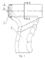
Figure 1 is a structural schematic view of a main machine in an embodiment of the present invention; -
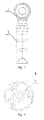
Figure 2 is a right view ofFigure 1 ; -
Figure 3 is a view ofFigure 1 taken along line A-A; -
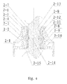
Figure 4 is a structural schematic view of a locking seat in an embodiment of the present invention; -
Figure 5 is an overall structural schematic view of an embodiment of the present invention. - Hereinafter further description will be made by incorporating figures and embodiments to illustrate the present invention.
- As can be seen from
Figure 1 to Figure 5 : - A cranial drill, comprises a main machine, a reducer and a locking seat that are successively threadedly connected, having a turning transmission rod interconnected to the output shaft of the reducer inserted in the locking seat, the main machine comprises a
handle 1 in the lower portion, and a containing part 2 in the upper portion, the containing part 2 having a stator androtor 5 of a DC electric motor provided therein, thewall 4 of the containing part 2 defining the housing of the stator of the DC electric motor. Ablock plate 6 with holes is arranged in the rear portion of the containing part 2, dividing which into two cavities with the front cavity arranged with a stator of the electric motor,end cover 3 is threadedly connected with the rear end of the containing part 2 in tight fitting. The wires of the stator of the DC electric motor go through the holes on theblock plate 6, enter the inside of thehandle 1 after passing through the rear cavity. All wires of the stator of the DC electric motor have waterproof layer arranged thereon. - The locking seat comprises a flange 2-1 with a through hole. Two bearings 2-8 are arranged on the inner wall of the small cylinder on the upside of the flange, respectively positioned below the outer wall 2-7 and above a pressing member 2-15, and between which a supporting member 2-12 is arranged. An upper bottom face 2-10 is arranged with a pressing member 2-15 threadedly connected with the inner wall of the upper bottom face for tightly abutting the bearings 2-8 and the supporting member 2-12. The two bearings can effectively ensures smooth rotation of the transmission rod to produce lesser heat, while the existence of the supporting member 2-12 adds to the firmness between the bearings to reduce the likelihood of detachment.
- The flange is also provided with a locking sleeve 2-2 having a first protrusion 2-5 provided on the inner wall of the upper portion thereof and a second protrusion 2-3 provided on the inner wall of the lower portion thereof. A spring 2-9 is arranged between the second protrusion 2-3 and the upper bottom face 2-10 of the flange. A pressing plate 2-6 is threadedly connected with an outer wall 7 of the top portion of the small cylinder on the upside of the flange and presses against the first protrusion 2-5. Holes of various sizes are provided on the inner wall of the small cylinder where corresponds to the second protrusion 2-3 and on the supporting member 2-12 to form stepped holes 2-11 which are provided with steel balls 2-4 therein. The diameter of the hole on the inner wall of the small cylinder is greater than that of the steel ball 2-4, and the diameter of the hole on the supporting member 2-12 is less than that of the steel ball 2-4.
- A transmission rod 2-13 is provided with a groove 2-14 in the corresponding position to the stepped holes 2-11. The inner wall of the big cylinder on the lower side of the flange 2-1 is provided with inner threads. In this embodiment, the number of stepped holes 2-11 and steel balls 2-4 are both counted to be two. As a variant, the number of steel balls and stepped holes may be set to be three, so that an improved locking effect is provided.
- The techniques described herein are exemplary, and should not be construed as implying any particular limitation on the present disclosure. It should be understood that various alternatives, combinations and modifications could be devised by those skilled in the art without departing from the technical scheme content of the present invention. The present disclosure is intended to embrace all alternatives, modifications and variances that fall within the scope of the appended claims.
Claims (8)
- A cranial drill, comprising a main machine, a reducer and a locking seat that are successively threadedly connected, having a drill transmission rod interconnected to an output shaft of the reducer inserted in the locking seat, characterized in that, the main machine comprises a handle (1) in the lower portion, and a containing part (2) in the upper portion, the containing part (2) having a stator and rotor (5) of a DC electric motor provided therein, a wall (4) of the containing part (2) defining a housing of the stator of the DC electric motor.
- The cranial drill according to claim 1, characterized in that, the locking seat comprises: a flange (2-1) with a through hole, an inner wall of a small cylinder on the upside of the flange arranged with bearings (2-8) and supporting members (2-12) that support the bearings (2-8), the flange also provided with a locking sleeve (2-2) which is arranged with a first protrusion (2-5) on the inner wall of the upper portion thereof and a second protrusion (2-3) on the inner wall of the lower portion thereof; a spring (2-9) is arranged between the second protrusion (2-3) and the upper bottom face (2-10) of the flange; a pressing plate (2-6) is threadedly connected with an outer wall (2-7) of a top portion of the small cylinder on the upside of the flange and presses against the first protrusion (2-5); holes of various sizes are provided on the inner wall of the small cylinder corresponding to the second protrusion (2-3) and on the supporting members (2-12) to form stepped holes (2-11) which are provided with steel balls (2-4) therein.
- The cranial drill according to claim 2, characterized in that, the upper bottom face (2-10) is arranged with a pressing member (2-15) threadedly connected with the inner wall of the upper bottom face for tightly abutting the bearings (2-8) and the supporting member (2-12).
- The cranial drill according to claim 3, characterized in that, the bearings (2-8) are numbered to be two which are respectively positioned below the outer wall (2-7) and above the pressing members (2-15).
- The cranial drill according to claim 4, characterized in that, the inner wall of the big cylinder on the lower side of the flange (2-1) is provided with inner threads.
- The cranial drill according to any of claims from 1 or 5, characterized in that, the rear portion of the containing part (2) is arranged with a blocking plate (6) with holes, an end cover (3) is threadedly connected with the rear end of the containing part (2) in tight fitting; wires of the stator of the DC electric motor go through the holes on the block plate (6) and enter the inside of the handle (1).
- The cranial drill according to claim 6, characterized in that, all wires inside the stator of the DC electric motor have waterproof layer arranged thereon.
- The cranial drill according to claim 7, characterized in that, the output shaft of the reducer is provided with a lip-shaped sealing ring.
Applications Claiming Priority (2)
| Application Number | Priority Date | Filing Date | Title |
|---|---|---|---|
| CN2010102980843A CN101926670B (en) | 2010-09-30 | 2010-09-30 | Craniotomy drill |
| PCT/CN2011/078827 WO2012041135A1 (en) | 2010-09-30 | 2011-08-24 | Craniotomy drill |
Publications (3)
| Publication Number | Publication Date |
|---|---|
| EP2623047A1 true EP2623047A1 (en) | 2013-08-07 |
| EP2623047A4 EP2623047A4 (en) | 2017-06-07 |
| EP2623047B1 EP2623047B1 (en) | 2018-05-09 |
Family
ID=43366292
Family Applications (1)
| Application Number | Title | Priority Date | Filing Date |
|---|---|---|---|
| EP11828031.2A Not-in-force EP2623047B1 (en) | 2010-09-30 | 2011-08-24 | Craniotomy drill |
Country Status (5)
| Country | Link |
|---|---|
| US (1) | US9295480B2 (en) |
| EP (1) | EP2623047B1 (en) |
| CN (1) | CN101926670B (en) |
| ES (1) | ES2682668T3 (en) |
| WO (1) | WO2012041135A1 (en) |
Families Citing this family (14)
| Publication number | Priority date | Publication date | Assignee | Title |
|---|---|---|---|---|
| CN101972157B (en) * | 2010-09-30 | 2011-12-21 | 重庆润泽医疗器械有限公司 | Drill bit locking device and drill bit |
| CN101926670B (en) * | 2010-09-30 | 2013-05-08 | 重庆润泽医疗器械有限公司 | Craniotomy drill |
| CN101926671B (en) * | 2010-09-30 | 2011-08-31 | 重庆润泽医疗器械有限公司 | Locking equipment for drill and drill |
| US11135026B2 (en) | 2012-05-11 | 2021-10-05 | Peter L. Bono | Robotic surgical system |
| US10194922B2 (en) | 2012-05-11 | 2019-02-05 | Peter L. Bono | Rotary oscillating bone, cartilage, and disk removal tool assembly |
| US10835263B2 (en) | 2016-11-17 | 2020-11-17 | Peter L. Bono | Rotary oscillating surgical tool |
| CN110087566B (en) * | 2016-10-31 | 2022-04-05 | 捷迈有限公司 | Surgical power tool with critical error handling procedures |
| US12408984B2 (en) | 2016-11-17 | 2025-09-09 | Globus Medical, Inc. | Surgical image system and method |
| WO2019083983A2 (en) | 2017-10-23 | 2019-05-02 | Bono Peter L | Rotary oscillating/reciprocating surgical tool |
| CN111970984B (en) | 2018-01-12 | 2025-01-28 | 格罗伯斯医疗有限公司 | Robotic surgery control system |
| EP3876860A1 (en) | 2018-11-06 | 2021-09-15 | Bono, Peter L. | Robotic surgical system and method |
| IT201900020576A1 (en) | 2019-11-07 | 2021-05-07 | Medacta Int Sa | HANDLE FOR RASPA AND SURGICAL DEVICE INCLUDING SAID HANDLE |
| USD933820S1 (en) * | 2020-03-04 | 2021-10-19 | Olympus Corporation | Handle for surgical device |
| USD935017S1 (en) * | 2020-03-31 | 2021-11-02 | Olympus Corporation | Controller for endoscope |
Family Cites Families (30)
| Publication number | Priority date | Publication date | Assignee | Title |
|---|---|---|---|---|
| US3709630A (en) * | 1969-10-28 | 1973-01-09 | Howmet Int Inc | Pneumatic motor for medical instruments |
| US3734207A (en) * | 1971-12-27 | 1973-05-22 | M Fishbein | Battery powered orthopedic cutting tool |
| US4199160A (en) * | 1978-05-17 | 1980-04-22 | Minnesota Mining And Manufacturing Company | Surgical drill chuck |
| US4692073A (en) * | 1985-02-25 | 1987-09-08 | Martindell J Richard | Handle adapter and chuck apparatus for power bits |
| US5093593A (en) * | 1990-12-18 | 1992-03-03 | Stryker Corporation | Surgical handpiece with motor having positive sensor location |
| US5505737A (en) * | 1994-07-01 | 1996-04-09 | Midas Rex Pneumatic Tools, Inc. | Quick release coupling for a dissecting tool |
| US6270087B1 (en) * | 1994-07-27 | 2001-08-07 | Mednext, Inc. | Tool shaft coupler |
| US6062575A (en) * | 1994-07-27 | 2000-05-16 | Mednext, Inc. | Tool shaft coupler |
| US5490683A (en) * | 1994-07-27 | 1996-02-13 | Mednext Inc. | Tool shaft coupler |
| US5591170A (en) * | 1994-10-14 | 1997-01-07 | Genesis Orthopedics | Intramedullary bone cutting saw |
| DE19619774A1 (en) * | 1996-05-15 | 1997-11-20 | Promed Gmbh | Processing device, esp. with cutter or abrasive tool for polishing surfaces |
| GB0111535D0 (en) * | 2001-05-11 | 2001-07-04 | Johnson Electric Sa | Gear motor for power tool |
| US6554290B2 (en) * | 2001-10-03 | 2003-04-29 | Kun-Tan Lin | Tool structure for clamping a tool head quickly |
| GB2382048A (en) * | 2001-11-20 | 2003-05-21 | Black & Decker Inc | Pivoting electrical connection for a power tool |
| US20030136134A1 (en) * | 2002-01-18 | 2003-07-24 | Pun John Y. | Fluid and air heat exchanger and method |
| CA3004862A1 (en) * | 2002-05-31 | 2003-12-11 | Teleflex Medical Devices S.A R.L. | Apparatus and method to access bone marrow |
| US9504477B2 (en) * | 2003-05-30 | 2016-11-29 | Vidacare LLC | Powered driver |
| US20050116429A1 (en) * | 2003-12-01 | 2005-06-02 | Sheng-Ming Chang | Fast and convenient operation structure of a screwdriver head socket |
| EP1871242B1 (en) * | 2005-04-16 | 2017-09-27 | Aesculap AG | Surgical machine and method for controlling and/or regulating the same |
| CN2855334Y (en) * | 2005-12-21 | 2007-01-10 | 北京茵普兰科技发展有限公司 | Combined operation power gun (I-shape) |
| US8480673B2 (en) * | 2006-06-01 | 2013-07-09 | Osteo Innovations Llc | Cavity creation device and methods of use |
| CN1931103A (en) * | 2006-09-30 | 2007-03-21 | 梁雄 | A multi-functional surgical device for orthopedics and its automatic control method |
| CN201019815Y (en) * | 2006-11-14 | 2008-02-13 | 梁雄 | A multi-functional operation instrument for orthopedics |
| CN101045006A (en) * | 2007-04-16 | 2007-10-03 | 苏州华晟手术医疗器械有限公司 | Medical electric drill |
| CN201198128Y (en) * | 2008-02-05 | 2009-02-25 | 胡振钱 | Fastener converter for electric hammer |
| CN201223435Y (en) * | 2008-07-29 | 2009-04-22 | 刘洪波 | Portable multifunctional surgical instruments for orthopedic surgery |
| CN101507647B (en) * | 2009-03-26 | 2012-02-01 | 中国人民解放军第二军医大学 | Portable chargeable multifunctional skull brad awl |
| CN201798778U (en) * | 2010-09-30 | 2011-04-20 | 重庆润泽医疗器械有限公司 | Skull dissection drill |
| CN201822887U (en) * | 2010-09-30 | 2011-05-11 | 重庆润泽医疗器械有限公司 | Craniotomy drill main machine |
| CN101926670B (en) * | 2010-09-30 | 2013-05-08 | 重庆润泽医疗器械有限公司 | Craniotomy drill |
-
2010
- 2010-09-30 CN CN2010102980843A patent/CN101926670B/en not_active Withdrawn - After Issue
-
2011
- 2011-08-24 US US13/823,077 patent/US9295480B2/en not_active Expired - Fee Related
- 2011-08-24 EP EP11828031.2A patent/EP2623047B1/en not_active Not-in-force
- 2011-08-24 ES ES11828031.2T patent/ES2682668T3/en active Active
- 2011-08-24 WO PCT/CN2011/078827 patent/WO2012041135A1/en not_active Ceased
Non-Patent Citations (1)
| Title |
|---|
| See references of WO2012041135A1 * |
Also Published As
| Publication number | Publication date |
|---|---|
| CN101926670A (en) | 2010-12-29 |
| CN101926670B (en) | 2013-05-08 |
| EP2623047A4 (en) | 2017-06-07 |
| US9295480B2 (en) | 2016-03-29 |
| EP2623047B1 (en) | 2018-05-09 |
| WO2012041135A1 (en) | 2012-04-05 |
| US20130178856A1 (en) | 2013-07-11 |
| ES2682668T3 (en) | 2018-09-21 |
Similar Documents
| Publication | Publication Date | Title |
|---|---|---|
| EP2623047B1 (en) | Craniotomy drill | |
| EP2623048B1 (en) | Drill bit locking device and drill bit | |
| EP2381062A3 (en) | Rotary steerable tool | |
| EP1879261A3 (en) | Spring lock interface engagement system | |
| EP2623046A1 (en) | Drill head locking apparatus and drill head | |
| EP2623052A1 (en) | Surgical milling cutter | |
| CN201558985U (en) | Cutter | |
| CN201798778U (en) | Skull dissection drill | |
| CN202920325U (en) | Screw for fixing bones and special spanner thereof | |
| CN202028844U (en) | Novel screw tap | |
| CN103831772B (en) | Small-sized hex nut magnetic holds tool | |
| CN210677209U (en) | Gear hobbing tool for synchronizer gear hub | |
| CN202761336U (en) | File for bone surgery | |
| CN202559764U (en) | Rotation type steel bar binding wire hook | |
| CN203527926U (en) | Improved household oil press | |
| CN209800505U (en) | anti-loosening copper non-standard nut | |
| CN213318776U (en) | Automatic bolt tightening assembly for mobile phone | |
| CN216165601U (en) | Clamping device is used in rubber overshoes processing | |
| CN203668669U (en) | Transmission wheel of sewing machine | |
| CN204655527U (en) | The broken medicine device of Intensive Care Therapy | |
| CN215035923U (en) | Universal dividing head strong milling locking device | |
| CN211220458U (en) | Gear-shaving machine tool-changing spanner | |
| CN203314344U (en) | Novel comb | |
| CN202426256U (en) | Novel grinding cup with integrated cup and cover | |
| CN204471267U (en) | T-shaped spanner |
Legal Events
| Date | Code | Title | Description |
|---|---|---|---|
| PUAI | Public reference made under article 153(3) epc to a published international application that has entered the european phase |
Free format text: ORIGINAL CODE: 0009012 |
|
| 17P | Request for examination filed |
Effective date: 20130429 |
|
| AK | Designated contracting states |
Kind code of ref document: A1 Designated state(s): AL AT BE BG CH CY CZ DE DK EE ES FI FR GB GR HR HU IE IS IT LI LT LU LV MC MK MT NL NO PL PT RO RS SE SI SK SM TR |
|
| DAX | Request for extension of the european patent (deleted) | ||
| RA4 | Supplementary search report drawn up and despatched (corrected) |
Effective date: 20170511 |
|
| RIC1 | Information provided on ipc code assigned before grant |
Ipc: A61B 17/16 20060101AFI20170504BHEP |
|
| STAA | Information on the status of an ep patent application or granted ep patent |
Free format text: STATUS: REQUEST FOR EXAMINATION WAS MADE |
|
| R17P | Request for examination filed (corrected) |
Effective date: 20130429 |
|
| GRAP | Despatch of communication of intention to grant a patent |
Free format text: ORIGINAL CODE: EPIDOSNIGR1 |
|
| STAA | Information on the status of an ep patent application or granted ep patent |
Free format text: STATUS: GRANT OF PATENT IS INTENDED |
|
| INTG | Intention to grant announced |
Effective date: 20180108 |
|
| GRAS | Grant fee paid |
Free format text: ORIGINAL CODE: EPIDOSNIGR3 |
|
| GRAA | (expected) grant |
Free format text: ORIGINAL CODE: 0009210 |
|
| STAA | Information on the status of an ep patent application or granted ep patent |
Free format text: STATUS: THE PATENT HAS BEEN GRANTED |
|
| RAP1 | Party data changed (applicant data changed or rights of an application transferred) |
Owner name: CHONGQING RUZER PHARMACEUTICAL CO., LTD. |
|
| AK | Designated contracting states |
Kind code of ref document: B1 Designated state(s): AL AT BE BG CH CY CZ DE DK EE ES FI FR GB GR HR HU IE IS IT LI LT LU LV MC MK MT NL NO PL PT RO RS SE SI SK SM TR |
|
| REG | Reference to a national code |
Ref country code: GB Ref legal event code: FG4D |
|
| REG | Reference to a national code |
Ref country code: CH Ref legal event code: EP Ref country code: AT Ref legal event code: REF Ref document number: 996794 Country of ref document: AT Kind code of ref document: T Effective date: 20180515 |
|
| REG | Reference to a national code |
Ref country code: DE Ref legal event code: R096 Ref document number: 602011048286 Country of ref document: DE Ref country code: IE Ref legal event code: FG4D |
|
| REG | Reference to a national code |
Ref country code: FR Ref legal event code: PLFP Year of fee payment: 8 |
|
| REG | Reference to a national code |
Ref country code: NL Ref legal event code: MP Effective date: 20180509 |
|
| REG | Reference to a national code |
Ref country code: ES Ref legal event code: FG2A Ref document number: 2682668 Country of ref document: ES Kind code of ref document: T3 Effective date: 20180921 |
|
| REG | Reference to a national code |
Ref country code: LT Ref legal event code: MG4D |
|
| PG25 | Lapsed in a contracting state [announced via postgrant information from national office to epo] |
Ref country code: NO Free format text: LAPSE BECAUSE OF FAILURE TO SUBMIT A TRANSLATION OF THE DESCRIPTION OR TO PAY THE FEE WITHIN THE PRESCRIBED TIME-LIMIT Effective date: 20180809 Ref country code: FI Free format text: LAPSE BECAUSE OF FAILURE TO SUBMIT A TRANSLATION OF THE DESCRIPTION OR TO PAY THE FEE WITHIN THE PRESCRIBED TIME-LIMIT Effective date: 20180509 Ref country code: LT Free format text: LAPSE BECAUSE OF FAILURE TO SUBMIT A TRANSLATION OF THE DESCRIPTION OR TO PAY THE FEE WITHIN THE PRESCRIBED TIME-LIMIT Effective date: 20180509 Ref country code: SE Free format text: LAPSE BECAUSE OF FAILURE TO SUBMIT A TRANSLATION OF THE DESCRIPTION OR TO PAY THE FEE WITHIN THE PRESCRIBED TIME-LIMIT Effective date: 20180509 Ref country code: BG Free format text: LAPSE BECAUSE OF FAILURE TO SUBMIT A TRANSLATION OF THE DESCRIPTION OR TO PAY THE FEE WITHIN THE PRESCRIBED TIME-LIMIT Effective date: 20180809 |
|
| PG25 | Lapsed in a contracting state [announced via postgrant information from national office to epo] |
Ref country code: LV Free format text: LAPSE BECAUSE OF FAILURE TO SUBMIT A TRANSLATION OF THE DESCRIPTION OR TO PAY THE FEE WITHIN THE PRESCRIBED TIME-LIMIT Effective date: 20180509 Ref country code: NL Free format text: LAPSE BECAUSE OF FAILURE TO SUBMIT A TRANSLATION OF THE DESCRIPTION OR TO PAY THE FEE WITHIN THE PRESCRIBED TIME-LIMIT Effective date: 20180509 Ref country code: RS Free format text: LAPSE BECAUSE OF FAILURE TO SUBMIT A TRANSLATION OF THE DESCRIPTION OR TO PAY THE FEE WITHIN THE PRESCRIBED TIME-LIMIT Effective date: 20180509 Ref country code: GR Free format text: LAPSE BECAUSE OF FAILURE TO SUBMIT A TRANSLATION OF THE DESCRIPTION OR TO PAY THE FEE WITHIN THE PRESCRIBED TIME-LIMIT Effective date: 20180810 Ref country code: HR Free format text: LAPSE BECAUSE OF FAILURE TO SUBMIT A TRANSLATION OF THE DESCRIPTION OR TO PAY THE FEE WITHIN THE PRESCRIBED TIME-LIMIT Effective date: 20180509 |
|
| REG | Reference to a national code |
Ref country code: AT Ref legal event code: MK05 Ref document number: 996794 Country of ref document: AT Kind code of ref document: T Effective date: 20180509 |
|
| PG25 | Lapsed in a contracting state [announced via postgrant information from national office to epo] |
Ref country code: DK Free format text: LAPSE BECAUSE OF FAILURE TO SUBMIT A TRANSLATION OF THE DESCRIPTION OR TO PAY THE FEE WITHIN THE PRESCRIBED TIME-LIMIT Effective date: 20180509 Ref country code: EE Free format text: LAPSE BECAUSE OF FAILURE TO SUBMIT A TRANSLATION OF THE DESCRIPTION OR TO PAY THE FEE WITHIN THE PRESCRIBED TIME-LIMIT Effective date: 20180509 Ref country code: PL Free format text: LAPSE BECAUSE OF FAILURE TO SUBMIT A TRANSLATION OF THE DESCRIPTION OR TO PAY THE FEE WITHIN THE PRESCRIBED TIME-LIMIT Effective date: 20180509 Ref country code: AT Free format text: LAPSE BECAUSE OF FAILURE TO SUBMIT A TRANSLATION OF THE DESCRIPTION OR TO PAY THE FEE WITHIN THE PRESCRIBED TIME-LIMIT Effective date: 20180509 Ref country code: SK Free format text: LAPSE BECAUSE OF FAILURE TO SUBMIT A TRANSLATION OF THE DESCRIPTION OR TO PAY THE FEE WITHIN THE PRESCRIBED TIME-LIMIT Effective date: 20180509 Ref country code: CZ Free format text: LAPSE BECAUSE OF FAILURE TO SUBMIT A TRANSLATION OF THE DESCRIPTION OR TO PAY THE FEE WITHIN THE PRESCRIBED TIME-LIMIT Effective date: 20180509 Ref country code: RO Free format text: LAPSE BECAUSE OF FAILURE TO SUBMIT A TRANSLATION OF THE DESCRIPTION OR TO PAY THE FEE WITHIN THE PRESCRIBED TIME-LIMIT Effective date: 20180509 |
|
| REG | Reference to a national code |
Ref country code: DE Ref legal event code: R097 Ref document number: 602011048286 Country of ref document: DE |
|
| PG25 | Lapsed in a contracting state [announced via postgrant information from national office to epo] |
Ref country code: SM Free format text: LAPSE BECAUSE OF FAILURE TO SUBMIT A TRANSLATION OF THE DESCRIPTION OR TO PAY THE FEE WITHIN THE PRESCRIBED TIME-LIMIT Effective date: 20180509 |
|
| PLBE | No opposition filed within time limit |
Free format text: ORIGINAL CODE: 0009261 |
|
| STAA | Information on the status of an ep patent application or granted ep patent |
Free format text: STATUS: NO OPPOSITION FILED WITHIN TIME LIMIT |
|
| PG25 | Lapsed in a contracting state [announced via postgrant information from national office to epo] |
Ref country code: MC Free format text: LAPSE BECAUSE OF FAILURE TO SUBMIT A TRANSLATION OF THE DESCRIPTION OR TO PAY THE FEE WITHIN THE PRESCRIBED TIME-LIMIT Effective date: 20180509 |
|
| REG | Reference to a national code |
Ref country code: CH Ref legal event code: PL |
|
| 26N | No opposition filed |
Effective date: 20190212 |
|
| PG25 | Lapsed in a contracting state [announced via postgrant information from national office to epo] |
Ref country code: LI Free format text: LAPSE BECAUSE OF NON-PAYMENT OF DUE FEES Effective date: 20180831 Ref country code: LU Free format text: LAPSE BECAUSE OF NON-PAYMENT OF DUE FEES Effective date: 20180824 Ref country code: CH Free format text: LAPSE BECAUSE OF NON-PAYMENT OF DUE FEES Effective date: 20180831 |
|
| REG | Reference to a national code |
Ref country code: BE Ref legal event code: MM Effective date: 20180831 |
|
| PG25 | Lapsed in a contracting state [announced via postgrant information from national office to epo] |
Ref country code: SI Free format text: LAPSE BECAUSE OF FAILURE TO SUBMIT A TRANSLATION OF THE DESCRIPTION OR TO PAY THE FEE WITHIN THE PRESCRIBED TIME-LIMIT Effective date: 20180509 |
|
| PG25 | Lapsed in a contracting state [announced via postgrant information from national office to epo] |
Ref country code: BE Free format text: LAPSE BECAUSE OF NON-PAYMENT OF DUE FEES Effective date: 20180831 |
|
| PGFP | Annual fee paid to national office [announced via postgrant information from national office to epo] |
Ref country code: ES Payment date: 20190924 Year of fee payment: 9 Ref country code: FR Payment date: 20190822 Year of fee payment: 9 Ref country code: IT Payment date: 20190829 Year of fee payment: 9 |
|
| PG25 | Lapsed in a contracting state [announced via postgrant information from national office to epo] |
Ref country code: AL Free format text: LAPSE BECAUSE OF FAILURE TO SUBMIT A TRANSLATION OF THE DESCRIPTION OR TO PAY THE FEE WITHIN THE PRESCRIBED TIME-LIMIT Effective date: 20180509 |
|
| PGFP | Annual fee paid to national office [announced via postgrant information from national office to epo] |
Ref country code: GB Payment date: 20190821 Year of fee payment: 9 |
|
| PG25 | Lapsed in a contracting state [announced via postgrant information from national office to epo] |
Ref country code: MT Free format text: LAPSE BECAUSE OF NON-PAYMENT OF DUE FEES Effective date: 20180824 |
|
| PG25 | Lapsed in a contracting state [announced via postgrant information from national office to epo] |
Ref country code: TR Free format text: LAPSE BECAUSE OF FAILURE TO SUBMIT A TRANSLATION OF THE DESCRIPTION OR TO PAY THE FEE WITHIN THE PRESCRIBED TIME-LIMIT Effective date: 20180509 |
|
| PG25 | Lapsed in a contracting state [announced via postgrant information from national office to epo] |
Ref country code: PT Free format text: LAPSE BECAUSE OF FAILURE TO SUBMIT A TRANSLATION OF THE DESCRIPTION OR TO PAY THE FEE WITHIN THE PRESCRIBED TIME-LIMIT Effective date: 20180509 Ref country code: HU Free format text: LAPSE BECAUSE OF FAILURE TO SUBMIT A TRANSLATION OF THE DESCRIPTION OR TO PAY THE FEE WITHIN THE PRESCRIBED TIME-LIMIT; INVALID AB INITIO Effective date: 20110824 |
|
| PG25 | Lapsed in a contracting state [announced via postgrant information from national office to epo] |
Ref country code: MK Free format text: LAPSE BECAUSE OF NON-PAYMENT OF DUE FEES Effective date: 20180509 Ref country code: CY Free format text: LAPSE BECAUSE OF FAILURE TO SUBMIT A TRANSLATION OF THE DESCRIPTION OR TO PAY THE FEE WITHIN THE PRESCRIBED TIME-LIMIT Effective date: 20180509 Ref country code: IE Free format text: LAPSE BECAUSE OF NON-PAYMENT OF DUE FEES Effective date: 20180824 |
|
| PG25 | Lapsed in a contracting state [announced via postgrant information from national office to epo] |
Ref country code: IS Free format text: LAPSE BECAUSE OF FAILURE TO SUBMIT A TRANSLATION OF THE DESCRIPTION OR TO PAY THE FEE WITHIN THE PRESCRIBED TIME-LIMIT Effective date: 20180909 |
|
| PGFP | Annual fee paid to national office [announced via postgrant information from national office to epo] |
Ref country code: DE Payment date: 20200907 Year of fee payment: 10 |
|
| GBPC | Gb: european patent ceased through non-payment of renewal fee |
Effective date: 20200824 |
|
| PG25 | Lapsed in a contracting state [announced via postgrant information from national office to epo] |
Ref country code: FR Free format text: LAPSE BECAUSE OF NON-PAYMENT OF DUE FEES Effective date: 20200831 Ref country code: IT Free format text: LAPSE BECAUSE OF NON-PAYMENT OF DUE FEES Effective date: 20200824 |
|
| PG25 | Lapsed in a contracting state [announced via postgrant information from national office to epo] |
Ref country code: GB Free format text: LAPSE BECAUSE OF NON-PAYMENT OF DUE FEES Effective date: 20200824 |
|
| REG | Reference to a national code |
Ref country code: ES Ref legal event code: FD2A Effective date: 20220110 |
|
| REG | Reference to a national code |
Ref country code: DE Ref legal event code: R119 Ref document number: 602011048286 Country of ref document: DE |
|
| PG25 | Lapsed in a contracting state [announced via postgrant information from national office to epo] |
Ref country code: ES Free format text: LAPSE BECAUSE OF NON-PAYMENT OF DUE FEES Effective date: 20200825 |
|
| PG25 | Lapsed in a contracting state [announced via postgrant information from national office to epo] |
Ref country code: DE Free format text: LAPSE BECAUSE OF NON-PAYMENT OF DUE FEES Effective date: 20220301 |