EP2623046B1 - Drill head locking apparatus and drill head - Google Patents
Drill head locking apparatus and drill head Download PDFInfo
- Publication number
- EP2623046B1 EP2623046B1 EP11828028.8A EP11828028A EP2623046B1 EP 2623046 B1 EP2623046 B1 EP 2623046B1 EP 11828028 A EP11828028 A EP 11828028A EP 2623046 B1 EP2623046 B1 EP 2623046B1
- Authority
- EP
- European Patent Office
- Prior art keywords
- drill head
- flange
- wall
- locking apparatus
- conical
- Prior art date
- Legal status (The legal status is an assumption and is not a legal conclusion. Google has not performed a legal analysis and makes no representation as to the accuracy of the status listed.)
- Not-in-force
Links
- 230000005540 biological transmission Effects 0.000 claims description 16
- 238000001356 surgical procedure Methods 0.000 claims description 7
- 229910000831 Steel Inorganic materials 0.000 claims description 6
- 239000010959 steel Substances 0.000 claims description 6
- 230000000694 effects Effects 0.000 description 5
- 239000003638 chemical reducing agent Substances 0.000 description 4
- 230000013011 mating Effects 0.000 description 2
- 238000000034 method Methods 0.000 description 2
- 238000012986 modification Methods 0.000 description 2
- 230000004048 modification Effects 0.000 description 2
- 238000005299 abrasion Methods 0.000 description 1
- 210000000988 bone and bone Anatomy 0.000 description 1
- 230000006835 compression Effects 0.000 description 1
- 238000007906 compression Methods 0.000 description 1
- 230000008878 coupling Effects 0.000 description 1
- 238000010168 coupling process Methods 0.000 description 1
- 238000005859 coupling reaction Methods 0.000 description 1
- 238000007428 craniotomy Methods 0.000 description 1
- 238000003801 milling Methods 0.000 description 1
Images
Classifications
-
- A—HUMAN NECESSITIES
- A61—MEDICAL OR VETERINARY SCIENCE; HYGIENE
- A61B—DIAGNOSIS; SURGERY; IDENTIFICATION
- A61B17/00—Surgical instruments, devices or methods
- A61B17/16—Instruments for performing osteoclasis; Drills or chisels for bones; Trepans
- A61B17/1613—Component parts
- A61B17/162—Chucks or tool parts which are to be held in a chuck
-
- B—PERFORMING OPERATIONS; TRANSPORTING
- B23—MACHINE TOOLS; METAL-WORKING NOT OTHERWISE PROVIDED FOR
- B23B—TURNING; BORING
- B23B31/00—Chucks; Expansion mandrels; Adaptations thereof for remote control
- B23B31/02—Chucks
- B23B31/10—Chucks characterised by the retaining or gripping devices or their immediate operating means
-
- B—PERFORMING OPERATIONS; TRANSPORTING
- B23—MACHINE TOOLS; METAL-WORKING NOT OTHERWISE PROVIDED FOR
- B23B—TURNING; BORING
- B23B31/00—Chucks; Expansion mandrels; Adaptations thereof for remote control
- B23B31/02—Chucks
- B23B31/10—Chucks characterised by the retaining or gripping devices or their immediate operating means
- B23B31/107—Retention by laterally-acting detents, e.g. pins, screws, wedges; Retention by loose elements, e.g. balls
- B23B31/1071—Retention by balls
-
- A—HUMAN NECESSITIES
- A61—MEDICAL OR VETERINARY SCIENCE; HYGIENE
- A61B—DIAGNOSIS; SURGERY; IDENTIFICATION
- A61B17/00—Surgical instruments, devices or methods
- A61B17/16—Instruments for performing osteoclasis; Drills or chisels for bones; Trepans
- A61B17/1695—Trepans or craniotomes, i.e. specially adapted for drilling thin bones such as the skull
-
- Y—GENERAL TAGGING OF NEW TECHNOLOGICAL DEVELOPMENTS; GENERAL TAGGING OF CROSS-SECTIONAL TECHNOLOGIES SPANNING OVER SEVERAL SECTIONS OF THE IPC; TECHNICAL SUBJECTS COVERED BY FORMER USPC CROSS-REFERENCE ART COLLECTIONS [XRACs] AND DIGESTS
- Y10—TECHNICAL SUBJECTS COVERED BY FORMER USPC
- Y10S—TECHNICAL SUBJECTS COVERED BY FORMER USPC CROSS-REFERENCE ART COLLECTIONS [XRACs] AND DIGESTS
- Y10S279/00—Chucks or sockets
- Y10S279/904—Quick change socket
- Y10S279/905—Quick change socket with ball detent
-
- Y—GENERAL TAGGING OF NEW TECHNOLOGICAL DEVELOPMENTS; GENERAL TAGGING OF CROSS-SECTIONAL TECHNOLOGIES SPANNING OVER SEVERAL SECTIONS OF THE IPC; TECHNICAL SUBJECTS COVERED BY FORMER USPC CROSS-REFERENCE ART COLLECTIONS [XRACs] AND DIGESTS
- Y10—TECHNICAL SUBJECTS COVERED BY FORMER USPC
- Y10T—TECHNICAL SUBJECTS COVERED BY FORMER US CLASSIFICATION
- Y10T279/00—Chucks or sockets
- Y10T279/17—Socket type
-
- Y—GENERAL TAGGING OF NEW TECHNOLOGICAL DEVELOPMENTS; GENERAL TAGGING OF CROSS-SECTIONAL TECHNOLOGIES SPANNING OVER SEVERAL SECTIONS OF THE IPC; TECHNICAL SUBJECTS COVERED BY FORMER USPC CROSS-REFERENCE ART COLLECTIONS [XRACs] AND DIGESTS
- Y10—TECHNICAL SUBJECTS COVERED BY FORMER USPC
- Y10T—TECHNICAL SUBJECTS COVERED BY FORMER US CLASSIFICATION
- Y10T279/00—Chucks or sockets
- Y10T279/17—Socket type
- Y10T279/17128—Self-grasping
- Y10T279/17136—Yielding grasping jaws
- Y10T279/17145—Ball or roller
-
- Y—GENERAL TAGGING OF NEW TECHNOLOGICAL DEVELOPMENTS; GENERAL TAGGING OF CROSS-SECTIONAL TECHNOLOGIES SPANNING OVER SEVERAL SECTIONS OF THE IPC; TECHNICAL SUBJECTS COVERED BY FORMER USPC CROSS-REFERENCE ART COLLECTIONS [XRACs] AND DIGESTS
- Y10—TECHNICAL SUBJECTS COVERED BY FORMER USPC
- Y10T—TECHNICAL SUBJECTS COVERED BY FORMER US CLASSIFICATION
- Y10T279/00—Chucks or sockets
- Y10T279/17—Socket type
- Y10T279/17128—Self-grasping
- Y10T279/17171—One-way-clutch type
- Y10T279/17188—Side detent
- Y10T279/17196—Ball or roller
-
- Y—GENERAL TAGGING OF NEW TECHNOLOGICAL DEVELOPMENTS; GENERAL TAGGING OF CROSS-SECTIONAL TECHNOLOGIES SPANNING OVER SEVERAL SECTIONS OF THE IPC; TECHNICAL SUBJECTS COVERED BY FORMER USPC CROSS-REFERENCE ART COLLECTIONS [XRACs] AND DIGESTS
- Y10—TECHNICAL SUBJECTS COVERED BY FORMER USPC
- Y10T—TECHNICAL SUBJECTS COVERED BY FORMER US CLASSIFICATION
- Y10T279/00—Chucks or sockets
- Y10T279/17—Socket type
- Y10T279/17666—Radially reciprocating jaws
- Y10T279/17692—Moving-cam actuator
- Y10T279/17743—Reciprocating cam sleeve
-
- Y—GENERAL TAGGING OF NEW TECHNOLOGICAL DEVELOPMENTS; GENERAL TAGGING OF CROSS-SECTIONAL TECHNOLOGIES SPANNING OVER SEVERAL SECTIONS OF THE IPC; TECHNICAL SUBJECTS COVERED BY FORMER USPC CROSS-REFERENCE ART COLLECTIONS [XRACs] AND DIGESTS
- Y10—TECHNICAL SUBJECTS COVERED BY FORMER USPC
- Y10T—TECHNICAL SUBJECTS COVERED BY FORMER US CLASSIFICATION
- Y10T279/00—Chucks or sockets
- Y10T279/17—Socket type
- Y10T279/17666—Radially reciprocating jaws
- Y10T279/17692—Moving-cam actuator
- Y10T279/17743—Reciprocating cam sleeve
- Y10T279/17752—Ball or roller jaws
Definitions
- the present invention relates to a bone drill motor for use in surgery and, more particularly, to a drill head locking apparatus and a drill head thereof.
- the cranial drill comprises a main machine, a reducer, a locking seat and a drill head.
- the drill head comprises cutting edge in the front part and a transmission rod in the rear part.
- the drill has a transmission rod drill head, and the locking seat is threadedly connected to the front part of the reducer, having the drill head passing through the locking seat and coupled with the power output of the reducer.
- the locking seat effects tight locking of the transmission rod to prevent the detachment of the drill head in operation.
- the prior locking apparatus utilizing a trip to effect locking is inconvenient for mounting and difficult for using.
- US 5,490,683 describes apparatus and methods for coupling a driving shaft and a mating tool shaft to transmit rotational forces and axial tension and compression forces between the shafts.
- the object of the present invention is to provide a drill transmission rod locking apparatus and a drill head that are convenient for use.
- the object of the present invention is accomplished by adopting the following scheme.
- a drill head locking apparatus wherein the locking apparatus comprises: a flange having a through hole, bearings arranged on the inner wall of a small cylinder on the flange, a locking sleeve arranged over the flange, a protrusion arranged on the upper part of the inner wall of the locking sleeve, the lower part of the inner wall of the locking sleeve having a conical face.
- a spring is arranged between the bottom face of the conical face and an upper bottom face of the flange.
- a pressing plate is threadedly connected to the outer wall of the top part of the small cylinder on the upside of the flange and presses against the protrusion.
- a conical hole is arranged in the corresponding position on the wall of the small cylinder on the upside of the flange and on the conical face, and a steel ball is arranged in the conical hole.
- the bearings can be two which are respectively positioned below the outer wall and above the upper bottom face.
- a supporting member is arranged between the two bearings.
- the inner wall of the big cylinder on the underside of the flange is provided with inner threads.
- a drill head mating the noted drill head locking apparatus, comprises a cutting edge in the front part and a transmission rod in the rear part, wherein a groove is provided on the transmission rod.
Landscapes
- Health & Medical Sciences (AREA)
- Engineering & Computer Science (AREA)
- Surgery (AREA)
- Life Sciences & Earth Sciences (AREA)
- Mechanical Engineering (AREA)
- Medical Informatics (AREA)
- Animal Behavior & Ethology (AREA)
- Orthopedic Medicine & Surgery (AREA)
- Biomedical Technology (AREA)
- Heart & Thoracic Surgery (AREA)
- Oral & Maxillofacial Surgery (AREA)
- Molecular Biology (AREA)
- Nuclear Medicine, Radiotherapy & Molecular Imaging (AREA)
- General Health & Medical Sciences (AREA)
- Public Health (AREA)
- Veterinary Medicine (AREA)
- Dentistry (AREA)
- Surgical Instruments (AREA)
- Earth Drilling (AREA)
- Drilling Tools (AREA)
Description
- The present invention relates to a bone drill motor for use in surgery and, more particularly, to a drill head locking apparatus and a drill head thereof.
- In surgery, the cranial drill, milling cutter and abrasion drill are tools commonly used for craniotomy. The cranial drill comprises a main machine, a reducer, a locking seat and a drill head. The drill head comprises cutting edge in the front part and a transmission rod in the rear part. The drill has a transmission rod drill head, and the locking seat is threadedly connected to the front part of the reducer, having the drill head passing through the locking seat and coupled with the power output of the reducer. The locking seat effects tight locking of the transmission rod to prevent the detachment of the drill head in operation. The prior locking apparatus utilizing a trip to effect locking is inconvenient for mounting and difficult for using.
-
US 5,490,683 describes apparatus and methods for coupling a driving shaft and a mating tool shaft to transmit rotational forces and axial tension and compression forces between the shafts. - The object of the present invention is to provide a drill transmission rod locking apparatus and a drill head that are convenient for use.
- The object of the present invention is accomplished by adopting the following scheme.
- A drill head locking apparatus, wherein the locking apparatus comprises: a flange having a through hole, bearings arranged on the inner wall of a small cylinder on the flange, a locking sleeve arranged over the flange, a protrusion arranged on the upper part of the inner wall of the locking sleeve, the lower part of the inner wall of the locking sleeve having a conical face. A spring is arranged between the bottom face of the conical face and an upper bottom face of the flange. A pressing plate is threadedly connected to the outer wall of the top part of the small cylinder on the upside of the flange and presses against the protrusion. A conical hole is arranged in the corresponding position on the wall of the small cylinder on the upside of the flange and on the conical face, and a steel ball is arranged in the conical hole.
- In order to transfer uniform force to the transmission rod, the bearings can be two which are respectively positioned below the outer wall and above the upper bottom face.
- In order to ensure the bearings are secured, a supporting member is arranged between the two bearings.
- In order to facilitate connecting the reducer, the inner wall of the big cylinder on the underside of the flange is provided with inner threads.
- A drill head, mating the noted drill head locking apparatus, comprises a cutting edge in the front part and a transmission rod in the rear part, wherein a groove is provided on the transmission rod.
- By adopting this structure, when the transmission rod is to be inserted, one only has to press down the locking sleeve, then the conical face moves down and the steel ball roll toward outside. When the transmission rod reaches the designated position, one releases the locking sleeve which moves up under the effect of the spring, the conical face engages the steel ball and moves inwardly to snap into the snap-slot on the transmission rod which is thus secured. In such a locking manner, the locking and loosening operations are easy and convenient to apply, providing a firm securing effect when in locking status and improved safety.
-
-
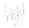
Figure 1 is a structural schematic view of a drill head locking apparatus in an embodiment of the present invention; -
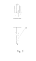
Figure 2 is a structural schematic view of a drill head in an embodiment of the present invention. - Hereinafter further description will be made by incorporating figures and embodiments to illustrate the present invention.
- As can be seen from
Figure 1 to Figure 2 : - A drill head, comprises a cutting edge in the front part and a transmission rod in the rear part, with a
groove 14 provided on thetransmission rod 13. - A drill head locking apparatus comprises a
flange 1 with a through hole. The inner wall of the small cylinder on the upside of the flange is arranged withbearings 8 thereon, which are numbered to be two and respectively positioned below theouter wall 7 and above thetop bottom face 10. A supportingmember 12 is arranged between the twobearings 8, which may effectively ensure the smooth rotation of the transmission rod to produce lesser heat. A pressingmember 15 is threadedly connected to theupper bottom face 10, thereby tightly abutting thebearings 8 and the supportingmember 12 and adding to the firmness between thebearings 8 to reduce the likelihood of detachment. Alocking sleeve 2 is arranged over the flange, with aprotrusion 5 arranged on the upper part of the inner wall of thelocking sleeve 2, the lower part of the inner wall of thelocking sleeve 2 having aconical face 3. A spring 9 is arranged between the bottom face of theconical face 3 and anupper bottom face 10 of the flange. Apressing plate 6 is threadedly connected on theouter wall 7 of the top part of the small cylinder on the flange and presses against theprotrusion 5. Aconical hole 11, leading to the through hole of the flange, is arranged on the wall of the small cylinder on the flange, and asteel ball 4 is arranged in theconical hole 11. Agroove 14 is provided on thedrill transmission rod 13 in the corresponding position to theconical hole 11. The inner wall of the big cylinder on the underside of theflange 1 is provided with inner threads. In this embodiment, theconical holes 11 and thesteel balls 4 can sure be numbered to be two, and as a variant, may be set to be three respectively, so that an improved locking effect is offered. - The techniques described herein are exemplary, and should not be construed as implying any particular limitation on the present disclosure. It should be understood that various alternatives, combinations and modifications could be devised by those skilled in the art without departing from the technical scheme content of the present invention. The present disclosure is intended to embrace all alternatives, modifications and variances that fall within the scope of the appended claims.
Claims (5)
- A drill head locking apparatus suitable for use in surgery, wherein the apparatus comprises a flange (1) having a through hole, a bearing (8) arranged on the inner wall of a small cylinder on the flange, a locking sleeve (2) arranged over the flange, a protrusion (5) arranged on the upper part of the inner wall of the locking sleeve (2), the lower part of the inner wall of the locking sleeve (2) having a conical face (3); a spring (9) is arranged between the bottom face of the conical face (3) and an upper bottom face (10) of the flange; a pressing plate (6) is threadedly connected to the outer wall (7) of the top part of the small cylinder on the upside of the flange and presses against the protrusion (5); a conical hole (11) is arranged in the corresponding position on the wall of the small cylinder on the upside of the flange and on the conical face (3), and a steel ball (4) is arranged in the conical hole (11).
- The drill head locking apparatus suitable for use in surgery according to claim 1, characterized in that, the bearings (8) are numbered to be two, respectively positioned below the outer wall (7) and above the upper bottom face (10).
- The drill head locking apparatus suitable for use in surgery according to claim 2, characterized in that, a supporting member (12) is arranged between the two bearings (8).
- The drill head locking apparatus suitable for use in surgery according to any of claims from 1 to 3, characterized in that, the inner wall of the big cylinder on the underside of the flange (1) is provided with inner threads.
- The drill head locking apparatus suitable for use in surgery according to any of claims 1 to 4 mated with a drill head, wherein the drill head comprises a cutting edge in a front part and a transmission rod (13) in a rear part, and a groove (14) is provided on the transmission rod (13).
Applications Claiming Priority (2)
| Application Number | Priority Date | Filing Date | Title |
|---|---|---|---|
| CN2010102980877A CN101926671B (en) | 2010-09-30 | 2010-09-30 | Locking equipment for drill and drill |
| PCT/CN2011/078809 WO2012041132A1 (en) | 2010-09-30 | 2011-08-24 | Drill head locking apparatus and drill head |
Publications (3)
| Publication Number | Publication Date |
|---|---|
| EP2623046A1 EP2623046A1 (en) | 2013-08-07 |
| EP2623046A4 EP2623046A4 (en) | 2014-04-02 |
| EP2623046B1 true EP2623046B1 (en) | 2015-08-05 |
Family
ID=43366293
Family Applications (1)
| Application Number | Title | Priority Date | Filing Date |
|---|---|---|---|
| EP11828028.8A Not-in-force EP2623046B1 (en) | 2010-09-30 | 2011-08-24 | Drill head locking apparatus and drill head |
Country Status (4)
| Country | Link |
|---|---|
| US (1) | US9254136B2 (en) |
| EP (1) | EP2623046B1 (en) |
| CN (1) | CN101926671B (en) |
| WO (1) | WO2012041132A1 (en) |
Families Citing this family (5)
| Publication number | Priority date | Publication date | Assignee | Title |
|---|---|---|---|---|
| CN101972157B (en) * | 2010-09-30 | 2011-12-21 | 重庆润泽医疗器械有限公司 | Drill bit locking device and drill bit |
| CN101926671B (en) * | 2010-09-30 | 2011-08-31 | 重庆润泽医疗器械有限公司 | Locking equipment for drill and drill |
| CN107525483B (en) * | 2017-08-17 | 2019-06-28 | 安徽江淮汽车集团股份有限公司 | A kind of pressing device |
| CN108568867A (en) * | 2018-05-03 | 2018-09-25 | 仇晨艺 | A kind of carpenter's square hole electric hand drill |
| US11285899B2 (en) * | 2020-04-23 | 2022-03-29 | Caterpillar Inc. | Guard assembly |
Family Cites Families (23)
| Publication number | Priority date | Publication date | Assignee | Title |
|---|---|---|---|---|
| US4199160A (en) * | 1978-05-17 | 1980-04-22 | Minnesota Mining And Manufacturing Company | Surgical drill chuck |
| US4692073A (en) * | 1985-02-25 | 1987-09-08 | Martindell J Richard | Handle adapter and chuck apparatus for power bits |
| DE4103663A1 (en) * | 1991-02-07 | 1992-08-20 | Aesculap Ag | SURGICAL HANDPIECE |
| CN2121299U (en) * | 1992-03-10 | 1992-11-11 | 厉永明 | Fast-changeable drill bit clamping apparatus |
| US5505737A (en) * | 1994-07-01 | 1996-04-09 | Midas Rex Pneumatic Tools, Inc. | Quick release coupling for a dissecting tool |
| US5490683A (en) * | 1994-07-27 | 1996-02-13 | Mednext Inc. | Tool shaft coupler |
| US5989257A (en) * | 1998-03-11 | 1999-11-23 | Midas Rex L.P. | Redundant safety lock mechanism |
| CN2374694Y (en) * | 1999-05-14 | 2000-04-19 | 地质矿产部探矿工程研究所 | Safety clutch for drilling machine |
| US6235033B1 (en) * | 2000-04-19 | 2001-05-22 | Synthes (Usa) | Bone fixation assembly |
| US7011661B2 (en) * | 2001-03-21 | 2006-03-14 | Medtronic, Inc. | Surgical instrument with rotary cutting member and quick release coupling arrangement |
| US6554290B2 (en) * | 2001-10-03 | 2003-04-29 | Kun-Tan Lin | Tool structure for clamping a tool head quickly |
| ATE482045T1 (en) * | 2003-02-18 | 2010-10-15 | Greenlee Textron Inc | QUICK CHANGE SPINDLE UNIT FOR HOLE SAW |
| US20050116429A1 (en) * | 2003-12-01 | 2005-06-02 | Sheng-Ming Chang | Fast and convenient operation structure of a screwdriver head socket |
| CN2853239Y (en) * | 2006-01-12 | 2007-01-03 | 郑国良 | Device for quickly changing bit of rail drill |
| CN201198128Y (en) * | 2008-02-05 | 2009-02-25 | 胡振钱 | Fastener converter for electric hammer |
| CN201492470U (en) * | 2009-09-28 | 2010-06-02 | 郭毅军 | Medical bit connecting structure |
| CN101711702B (en) * | 2009-12-08 | 2011-06-01 | 贾恩鹏 | Special tool used by internal and external fixation instrument for orthopaedic medical treatment |
| CN201798776U (en) * | 2010-09-30 | 2011-04-20 | 重庆润泽医疗器械有限公司 | Drill bit locking device and drill bit |
| CN101926671B (en) * | 2010-09-30 | 2011-08-31 | 重庆润泽医疗器械有限公司 | Locking equipment for drill and drill |
| CN201798777U (en) * | 2010-09-30 | 2011-04-20 | 重庆润泽医疗器械有限公司 | Drill locking device and drill |
| CN201798778U (en) * | 2010-09-30 | 2011-04-20 | 重庆润泽医疗器械有限公司 | Skull dissection drill |
| CN101972157B (en) * | 2010-09-30 | 2011-12-21 | 重庆润泽医疗器械有限公司 | Drill bit locking device and drill bit |
| CN101926670B (en) * | 2010-09-30 | 2013-05-08 | 重庆润泽医疗器械有限公司 | Craniotomy drill |
-
2010
- 2010-09-30 CN CN2010102980877A patent/CN101926671B/en not_active Withdrawn - After Issue
-
2011
- 2011-08-24 US US13/823,087 patent/US9254136B2/en not_active Expired - Fee Related
- 2011-08-24 EP EP11828028.8A patent/EP2623046B1/en not_active Not-in-force
- 2011-08-24 WO PCT/CN2011/078809 patent/WO2012041132A1/en not_active Ceased
Also Published As
| Publication number | Publication date |
|---|---|
| US9254136B2 (en) | 2016-02-09 |
| CN101926671A (en) | 2010-12-29 |
| WO2012041132A1 (en) | 2012-04-05 |
| EP2623046A4 (en) | 2014-04-02 |
| US20130178857A1 (en) | 2013-07-11 |
| EP2623046A1 (en) | 2013-08-07 |
| CN101926671B (en) | 2011-08-31 |
Similar Documents
| Publication | Publication Date | Title |
|---|---|---|
| EP2623048B1 (en) | Drill bit locking device and drill bit | |
| EP2623047B1 (en) | Craniotomy drill | |
| EP2623046A1 (en) | Drill head locking apparatus and drill head | |
| WO2012045465A3 (en) | Hammer with a cutting attachment and a base body | |
| EP2644326A3 (en) | Housing and gearbox for drill or driver | |
| CN206509558U (en) | Walk the power head device of core type lathe | |
| KR20100076530A (en) | Cutter height adjustment system | |
| EP2623052B1 (en) | Surgical milling cutter | |
| WO2012173136A1 (en) | Golf club | |
| CN102943815A (en) | Eccentric bearing and multifunctional saw | |
| CN102009360B (en) | Scappling handle cutter | |
| CN203500314U (en) | Telescopic universal spindle coupling | |
| CN201624552U (en) | Connection structure of cooking machine motor shaft and knife shaft | |
| US8960633B2 (en) | Adjusting tool | |
| CN108360975B (en) | Core drill and core machine suitable for bituminous paving | |
| CN102962688B (en) | A kind of universal joint positioning fixture | |
| CN202894378U (en) | BT tool holder | |
| CN102825320A (en) | Strongly connected disc milling cutter dedicated to guide shoes of coal mining machines | |
| CN206754210U (en) | A kind of cross-axle universal shaft coupling of convenient disassembly | |
| KR200448585Y1 (en) | Jig for Gear Coupling Assembly | |
| CN204262891U (en) | The flexible overload protective device of drilling | |
| CN102974858A (en) | BT cutter handle | |
| AU2014101017A4 (en) | Clutch Device for Servo Synchronous Tapping Machines | |
| CN202412123U (en) | Force measuring chuck key for machine tool | |
| CN205614398U (en) | Module quick -replaceable power blade holder |
Legal Events
| Date | Code | Title | Description |
|---|---|---|---|
| PUAI | Public reference made under article 153(3) epc to a published international application that has entered the european phase |
Free format text: ORIGINAL CODE: 0009012 |
|
| 17P | Request for examination filed |
Effective date: 20130429 |
|
| AK | Designated contracting states |
Kind code of ref document: A1 Designated state(s): AL AT BE BG CH CY CZ DE DK EE ES FI FR GB GR HR HU IE IS IT LI LT LU LV MC MK MT NL NO PL PT RO RS SE SI SK SM TR |
|
| DAX | Request for extension of the european patent (deleted) | ||
| A4 | Supplementary search report drawn up and despatched |
Effective date: 20140227 |
|
| RIC1 | Information provided on ipc code assigned before grant |
Ipc: A61B 17/16 20060101AFI20140221BHEP |
|
| GRAP | Despatch of communication of intention to grant a patent |
Free format text: ORIGINAL CODE: EPIDOSNIGR1 |
|
| INTG | Intention to grant announced |
Effective date: 20150220 |
|
| RAP1 | Party data changed (applicant data changed or rights of an application transferred) |
Owner name: CHONGQING RUNZE PHARMACEUTICALS CO., LTD. |
|
| GRAS | Grant fee paid |
Free format text: ORIGINAL CODE: EPIDOSNIGR3 |
|
| GRAA | (expected) grant |
Free format text: ORIGINAL CODE: 0009210 |
|
| AK | Designated contracting states |
Kind code of ref document: B1 Designated state(s): AL AT BE BG CH CY CZ DE DK EE ES FI FR GB GR HR HU IE IS IT LI LT LU LV MC MK MT NL NO PL PT RO RS SE SI SK SM TR |
|
| REG | Reference to a national code |
Ref country code: GB Ref legal event code: FG4D |
|
| REG | Reference to a national code |
Ref country code: CH Ref legal event code: EP |
|
| REG | Reference to a national code |
Ref country code: AT Ref legal event code: REF Ref document number: 740219 Country of ref document: AT Kind code of ref document: T Effective date: 20150815 |
|
| REG | Reference to a national code |
Ref country code: IE Ref legal event code: FG4D |
|
| REG | Reference to a national code |
Ref country code: DE Ref legal event code: R096 Ref document number: 602011018551 Country of ref document: DE |
|
| REG | Reference to a national code |
Ref country code: AT Ref legal event code: MK05 Ref document number: 740219 Country of ref document: AT Kind code of ref document: T Effective date: 20150805 |
|
| REG | Reference to a national code |
Ref country code: LT Ref legal event code: MG4D |
|
| REG | Reference to a national code |
Ref country code: NL Ref legal event code: MP Effective date: 20150805 |
|
| PG25 | Lapsed in a contracting state [announced via postgrant information from national office to epo] |
Ref country code: FI Free format text: LAPSE BECAUSE OF FAILURE TO SUBMIT A TRANSLATION OF THE DESCRIPTION OR TO PAY THE FEE WITHIN THE PRESCRIBED TIME-LIMIT Effective date: 20150805 Ref country code: NO Free format text: LAPSE BECAUSE OF FAILURE TO SUBMIT A TRANSLATION OF THE DESCRIPTION OR TO PAY THE FEE WITHIN THE PRESCRIBED TIME-LIMIT Effective date: 20151105 Ref country code: GR Free format text: LAPSE BECAUSE OF FAILURE TO SUBMIT A TRANSLATION OF THE DESCRIPTION OR TO PAY THE FEE WITHIN THE PRESCRIBED TIME-LIMIT Effective date: 20151106 Ref country code: LT Free format text: LAPSE BECAUSE OF FAILURE TO SUBMIT A TRANSLATION OF THE DESCRIPTION OR TO PAY THE FEE WITHIN THE PRESCRIBED TIME-LIMIT Effective date: 20150805 Ref country code: LV Free format text: LAPSE BECAUSE OF FAILURE TO SUBMIT A TRANSLATION OF THE DESCRIPTION OR TO PAY THE FEE WITHIN THE PRESCRIBED TIME-LIMIT Effective date: 20150805 |
|
| PG25 | Lapsed in a contracting state [announced via postgrant information from national office to epo] |
Ref country code: SE Free format text: LAPSE BECAUSE OF FAILURE TO SUBMIT A TRANSLATION OF THE DESCRIPTION OR TO PAY THE FEE WITHIN THE PRESCRIBED TIME-LIMIT Effective date: 20150805 Ref country code: HR Free format text: LAPSE BECAUSE OF FAILURE TO SUBMIT A TRANSLATION OF THE DESCRIPTION OR TO PAY THE FEE WITHIN THE PRESCRIBED TIME-LIMIT Effective date: 20150805 Ref country code: PL Free format text: LAPSE BECAUSE OF FAILURE TO SUBMIT A TRANSLATION OF THE DESCRIPTION OR TO PAY THE FEE WITHIN THE PRESCRIBED TIME-LIMIT Effective date: 20150805 Ref country code: ES Free format text: LAPSE BECAUSE OF FAILURE TO SUBMIT A TRANSLATION OF THE DESCRIPTION OR TO PAY THE FEE WITHIN THE PRESCRIBED TIME-LIMIT Effective date: 20150805 Ref country code: RS Free format text: LAPSE BECAUSE OF FAILURE TO SUBMIT A TRANSLATION OF THE DESCRIPTION OR TO PAY THE FEE WITHIN THE PRESCRIBED TIME-LIMIT Effective date: 20150805 Ref country code: PT Free format text: LAPSE BECAUSE OF FAILURE TO SUBMIT A TRANSLATION OF THE DESCRIPTION OR TO PAY THE FEE WITHIN THE PRESCRIBED TIME-LIMIT Effective date: 20151207 Ref country code: AT Free format text: LAPSE BECAUSE OF FAILURE TO SUBMIT A TRANSLATION OF THE DESCRIPTION OR TO PAY THE FEE WITHIN THE PRESCRIBED TIME-LIMIT Effective date: 20150805 Ref country code: IS Free format text: LAPSE BECAUSE OF FAILURE TO SUBMIT A TRANSLATION OF THE DESCRIPTION OR TO PAY THE FEE WITHIN THE PRESCRIBED TIME-LIMIT Effective date: 20151205 |
|
| PG25 | Lapsed in a contracting state [announced via postgrant information from national office to epo] |
Ref country code: NL Free format text: LAPSE BECAUSE OF FAILURE TO SUBMIT A TRANSLATION OF THE DESCRIPTION OR TO PAY THE FEE WITHIN THE PRESCRIBED TIME-LIMIT Effective date: 20150805 |
|
| PG25 | Lapsed in a contracting state [announced via postgrant information from national office to epo] |
Ref country code: DK Free format text: LAPSE BECAUSE OF FAILURE TO SUBMIT A TRANSLATION OF THE DESCRIPTION OR TO PAY THE FEE WITHIN THE PRESCRIBED TIME-LIMIT Effective date: 20150805 Ref country code: CZ Free format text: LAPSE BECAUSE OF FAILURE TO SUBMIT A TRANSLATION OF THE DESCRIPTION OR TO PAY THE FEE WITHIN THE PRESCRIBED TIME-LIMIT Effective date: 20150805 Ref country code: EE Free format text: LAPSE BECAUSE OF FAILURE TO SUBMIT A TRANSLATION OF THE DESCRIPTION OR TO PAY THE FEE WITHIN THE PRESCRIBED TIME-LIMIT Effective date: 20150805 Ref country code: IT Free format text: LAPSE BECAUSE OF FAILURE TO SUBMIT A TRANSLATION OF THE DESCRIPTION OR TO PAY THE FEE WITHIN THE PRESCRIBED TIME-LIMIT Effective date: 20150805 Ref country code: SK Free format text: LAPSE BECAUSE OF FAILURE TO SUBMIT A TRANSLATION OF THE DESCRIPTION OR TO PAY THE FEE WITHIN THE PRESCRIBED TIME-LIMIT Effective date: 20150805 |
|
| REG | Reference to a national code |
Ref country code: DE Ref legal event code: R097 Ref document number: 602011018551 Country of ref document: DE |
|
| PG25 | Lapsed in a contracting state [announced via postgrant information from national office to epo] |
Ref country code: MC Free format text: LAPSE BECAUSE OF FAILURE TO SUBMIT A TRANSLATION OF THE DESCRIPTION OR TO PAY THE FEE WITHIN THE PRESCRIBED TIME-LIMIT Effective date: 20150805 Ref country code: RO Free format text: LAPSE BECAUSE OF FAILURE TO SUBMIT A TRANSLATION OF THE DESCRIPTION OR TO PAY THE FEE WITHIN THE PRESCRIBED TIME-LIMIT Effective date: 20150805 |
|
| REG | Reference to a national code |
Ref country code: IE Ref legal event code: MM4A |
|
| PLBE | No opposition filed within time limit |
Free format text: ORIGINAL CODE: 0009261 |
|
| STAA | Information on the status of an ep patent application or granted ep patent |
Free format text: STATUS: NO OPPOSITION FILED WITHIN TIME LIMIT |
|
| 26N | No opposition filed |
Effective date: 20160509 |
|
| PG25 | Lapsed in a contracting state [announced via postgrant information from national office to epo] |
Ref country code: IE Free format text: LAPSE BECAUSE OF NON-PAYMENT OF DUE FEES Effective date: 20150824 |
|
| PG25 | Lapsed in a contracting state [announced via postgrant information from national office to epo] |
Ref country code: SI Free format text: LAPSE BECAUSE OF FAILURE TO SUBMIT A TRANSLATION OF THE DESCRIPTION OR TO PAY THE FEE WITHIN THE PRESCRIBED TIME-LIMIT Effective date: 20150805 |
|
| REG | Reference to a national code |
Ref country code: FR Ref legal event code: ST Effective date: 20160907 |
|
| PG25 | Lapsed in a contracting state [announced via postgrant information from national office to epo] |
Ref country code: FR Free format text: LAPSE BECAUSE OF NON-PAYMENT OF DUE FEES Effective date: 20151005 |
|
| PG25 | Lapsed in a contracting state [announced via postgrant information from national office to epo] |
Ref country code: MT Free format text: LAPSE BECAUSE OF FAILURE TO SUBMIT A TRANSLATION OF THE DESCRIPTION OR TO PAY THE FEE WITHIN THE PRESCRIBED TIME-LIMIT Effective date: 20150805 |
|
| PG25 | Lapsed in a contracting state [announced via postgrant information from national office to epo] |
Ref country code: BG Free format text: LAPSE BECAUSE OF FAILURE TO SUBMIT A TRANSLATION OF THE DESCRIPTION OR TO PAY THE FEE WITHIN THE PRESCRIBED TIME-LIMIT Effective date: 20150805 Ref country code: HU Free format text: LAPSE BECAUSE OF FAILURE TO SUBMIT A TRANSLATION OF THE DESCRIPTION OR TO PAY THE FEE WITHIN THE PRESCRIBED TIME-LIMIT; INVALID AB INITIO Effective date: 20110824 Ref country code: SM Free format text: LAPSE BECAUSE OF FAILURE TO SUBMIT A TRANSLATION OF THE DESCRIPTION OR TO PAY THE FEE WITHIN THE PRESCRIBED TIME-LIMIT Effective date: 20150805 |
|
| PG25 | Lapsed in a contracting state [announced via postgrant information from national office to epo] |
Ref country code: CY Free format text: LAPSE BECAUSE OF FAILURE TO SUBMIT A TRANSLATION OF THE DESCRIPTION OR TO PAY THE FEE WITHIN THE PRESCRIBED TIME-LIMIT Effective date: 20150805 |
|
| PG25 | Lapsed in a contracting state [announced via postgrant information from national office to epo] |
Ref country code: BE Free format text: LAPSE BECAUSE OF NON-PAYMENT OF DUE FEES Effective date: 20150831 |
|
| PG25 | Lapsed in a contracting state [announced via postgrant information from national office to epo] |
Ref country code: LU Free format text: LAPSE BECAUSE OF NON-PAYMENT OF DUE FEES Effective date: 20150824 |
|
| PG25 | Lapsed in a contracting state [announced via postgrant information from national office to epo] |
Ref country code: MK Free format text: LAPSE BECAUSE OF FAILURE TO SUBMIT A TRANSLATION OF THE DESCRIPTION OR TO PAY THE FEE WITHIN THE PRESCRIBED TIME-LIMIT Effective date: 20150805 Ref country code: TR Free format text: LAPSE BECAUSE OF FAILURE TO SUBMIT A TRANSLATION OF THE DESCRIPTION OR TO PAY THE FEE WITHIN THE PRESCRIBED TIME-LIMIT Effective date: 20150805 |
|
| PG25 | Lapsed in a contracting state [announced via postgrant information from national office to epo] |
Ref country code: AL Free format text: LAPSE BECAUSE OF FAILURE TO SUBMIT A TRANSLATION OF THE DESCRIPTION OR TO PAY THE FEE WITHIN THE PRESCRIBED TIME-LIMIT Effective date: 20150805 |
|
| PGFP | Annual fee paid to national office [announced via postgrant information from national office to epo] |
Ref country code: GB Payment date: 20190806 Year of fee payment: 9 |
|
| PGFP | Annual fee paid to national office [announced via postgrant information from national office to epo] |
Ref country code: CH Payment date: 20190725 Year of fee payment: 9 |
|
| REG | Reference to a national code |
Ref country code: CH Ref legal event code: PL |
|
| GBPC | Gb: european patent ceased through non-payment of renewal fee |
Effective date: 20200824 |
|
| PG25 | Lapsed in a contracting state [announced via postgrant information from national office to epo] |
Ref country code: LI Free format text: LAPSE BECAUSE OF NON-PAYMENT OF DUE FEES Effective date: 20200831 Ref country code: CH Free format text: LAPSE BECAUSE OF NON-PAYMENT OF DUE FEES Effective date: 20200831 |
|
| PG25 | Lapsed in a contracting state [announced via postgrant information from national office to epo] |
Ref country code: GB Free format text: LAPSE BECAUSE OF NON-PAYMENT OF DUE FEES Effective date: 20200824 |
|
| PGFP | Annual fee paid to national office [announced via postgrant information from national office to epo] |
Ref country code: DE Payment date: 20210902 Year of fee payment: 11 |
|
| REG | Reference to a national code |
Ref country code: DE Ref legal event code: R119 Ref document number: 602011018551 Country of ref document: DE |
|
| PG25 | Lapsed in a contracting state [announced via postgrant information from national office to epo] |
Ref country code: DE Free format text: LAPSE BECAUSE OF NON-PAYMENT OF DUE FEES Effective date: 20230301 |