EP2620942A1 - Devices including shaped write coils - Google Patents
Devices including shaped write coils Download PDFInfo
- Publication number
- EP2620942A1 EP2620942A1 EP13152426.6A EP13152426A EP2620942A1 EP 2620942 A1 EP2620942 A1 EP 2620942A1 EP 13152426 A EP13152426 A EP 13152426A EP 2620942 A1 EP2620942 A1 EP 2620942A1
- Authority
- EP
- European Patent Office
- Prior art keywords
- coil
- write
- head
- shape
- turns
- Prior art date
- Legal status (The legal status is an assumption and is not a legal conclusion. Google has not performed a legal analysis and makes no representation as to the accuracy of the status listed.)
- Withdrawn
Links
- 238000010438 heat treatment Methods 0.000 description 5
- 238000000034 method Methods 0.000 description 3
- RYGMFSIKBFXOCR-UHFFFAOYSA-N Copper Chemical compound [Cu] RYGMFSIKBFXOCR-UHFFFAOYSA-N 0.000 description 1
- 229910052802 copper Inorganic materials 0.000 description 1
- 239000010949 copper Substances 0.000 description 1
- 238000013500 data storage Methods 0.000 description 1
- 230000001419 dependent effect Effects 0.000 description 1
- 239000000463 material Substances 0.000 description 1
- 235000012771 pancakes Nutrition 0.000 description 1
- 238000007493 shaping process Methods 0.000 description 1
Images


Classifications
-
- G—PHYSICS
- G11—INFORMATION STORAGE
- G11B—INFORMATION STORAGE BASED ON RELATIVE MOVEMENT BETWEEN RECORD CARRIER AND TRANSDUCER
- G11B5/00—Recording by magnetisation or demagnetisation of a record carrier; Reproducing by magnetic means; Record carriers therefor
- G11B5/127—Structure or manufacture of heads, e.g. inductive
- G11B5/31—Structure or manufacture of heads, e.g. inductive using thin films
- G11B5/3109—Details
- G11B5/3113—Details for improving the magnetic domain structure or avoiding the formation or displacement of undesirable magnetic domains
-
- F—MECHANICAL ENGINEERING; LIGHTING; HEATING; WEAPONS; BLASTING
- F02—COMBUSTION ENGINES; HOT-GAS OR COMBUSTION-PRODUCT ENGINE PLANTS
- F02M—SUPPLYING COMBUSTION ENGINES IN GENERAL WITH COMBUSTIBLE MIXTURES OR CONSTITUENTS THEREOF
- F02M21/00—Apparatus for supplying engines with non-liquid fuels, e.g. gaseous fuels stored in liquid form
- F02M21/02—Apparatus for supplying engines with non-liquid fuels, e.g. gaseous fuels stored in liquid form for gaseous fuels
- F02M21/0218—Details on the gaseous fuel supply system, e.g. tanks, valves, pipes, pumps, rails, injectors or mixers
- F02M21/0245—High pressure fuel supply systems; Rails; Pumps; Arrangement of valves
-
- F—MECHANICAL ENGINEERING; LIGHTING; HEATING; WEAPONS; BLASTING
- F02—COMBUSTION ENGINES; HOT-GAS OR COMBUSTION-PRODUCT ENGINE PLANTS
- F02M—SUPPLYING COMBUSTION ENGINES IN GENERAL WITH COMBUSTIBLE MIXTURES OR CONSTITUENTS THEREOF
- F02M21/00—Apparatus for supplying engines with non-liquid fuels, e.g. gaseous fuels stored in liquid form
- F02M21/02—Apparatus for supplying engines with non-liquid fuels, e.g. gaseous fuels stored in liquid form for gaseous fuels
- F02M21/0203—Apparatus for supplying engines with non-liquid fuels, e.g. gaseous fuels stored in liquid form for gaseous fuels characterised by the type of gaseous fuel
- F02M21/0215—Mixtures of gaseous fuels; Natural gas; Biogas; Mine gas; Landfill gas
-
- F—MECHANICAL ENGINEERING; LIGHTING; HEATING; WEAPONS; BLASTING
- F02—COMBUSTION ENGINES; HOT-GAS OR COMBUSTION-PRODUCT ENGINE PLANTS
- F02M—SUPPLYING COMBUSTION ENGINES IN GENERAL WITH COMBUSTIBLE MIXTURES OR CONSTITUENTS THEREOF
- F02M21/00—Apparatus for supplying engines with non-liquid fuels, e.g. gaseous fuels stored in liquid form
- F02M21/02—Apparatus for supplying engines with non-liquid fuels, e.g. gaseous fuels stored in liquid form for gaseous fuels
- F02M21/06—Apparatus for de-liquefying, e.g. by heating
-
- F—MECHANICAL ENGINEERING; LIGHTING; HEATING; WEAPONS; BLASTING
- F02—COMBUSTION ENGINES; HOT-GAS OR COMBUSTION-PRODUCT ENGINE PLANTS
- F02M—SUPPLYING COMBUSTION ENGINES IN GENERAL WITH COMBUSTIBLE MIXTURES OR CONSTITUENTS THEREOF
- F02M37/00—Apparatus or systems for feeding liquid fuel from storage containers to carburettors or fuel-injection apparatus; Arrangements for purifying liquid fuel specially adapted for, or arranged on, internal-combustion engines
- F02M37/0047—Layout or arrangement of systems for feeding fuel
- F02M37/0052—Details on the fuel return circuit; Arrangement of pressure regulators
- F02M37/0058—Returnless fuel systems, i.e. the fuel return lines are not entering the fuel tank
-
- G—PHYSICS
- G11—INFORMATION STORAGE
- G11B—INFORMATION STORAGE BASED ON RELATIVE MOVEMENT BETWEEN RECORD CARRIER AND TRANSDUCER
- G11B5/00—Recording by magnetisation or demagnetisation of a record carrier; Reproducing by magnetic means; Record carriers therefor
- G11B5/127—Structure or manufacture of heads, e.g. inductive
- G11B5/31—Structure or manufacture of heads, e.g. inductive using thin films
- G11B5/3109—Details
- G11B5/3116—Shaping of layers, poles or gaps for improving the form of the electrical signal transduced, e.g. for shielding, contour effect, equalizing, side flux fringing, cross talk reduction between heads or between heads and information tracks
-
- G—PHYSICS
- G11—INFORMATION STORAGE
- G11B—INFORMATION STORAGE BASED ON RELATIVE MOVEMENT BETWEEN RECORD CARRIER AND TRANSDUCER
- G11B5/00—Recording by magnetisation or demagnetisation of a record carrier; Reproducing by magnetic means; Record carriers therefor
- G11B5/127—Structure or manufacture of heads, e.g. inductive
- G11B5/31—Structure or manufacture of heads, e.g. inductive using thin films
- G11B5/3109—Details
- G11B5/312—Details for reducing flux leakage between the electrical coil layers and the magnetic cores or poles or between the magnetic cores or poles
- G11B5/3123—Details for reducing flux leakage between the electrical coil layers and the magnetic cores or poles or between the magnetic cores or poles by using special coil configurations or conductors
-
- G—PHYSICS
- G11—INFORMATION STORAGE
- G11B—INFORMATION STORAGE BASED ON RELATIVE MOVEMENT BETWEEN RECORD CARRIER AND TRANSDUCER
- G11B5/00—Recording by magnetisation or demagnetisation of a record carrier; Reproducing by magnetic means; Record carriers therefor
- G11B5/48—Disposition or mounting of heads or head supports relative to record carriers ; arrangements of heads, e.g. for scanning the record carrier to increase the relative speed
- G11B5/58—Disposition or mounting of heads or head supports relative to record carriers ; arrangements of heads, e.g. for scanning the record carrier to increase the relative speed with provision for moving the head for the purpose of maintaining alignment of the head relative to the record carrier during transducing operation, e.g. to compensate for surface irregularities of the latter or for track following
- G11B5/60—Fluid-dynamic spacing of heads from record-carriers
- G11B5/6005—Specially adapted for spacing from a rotating disc using a fluid cushion
- G11B5/6082—Design of the air bearing surface
Definitions
- Certain embodiments of the present disclosure are generally directed to methods and devices including read/write heads with shaped write coils.
- a head includes a write coil having multiple coil turns. A portion of the multiple coil turns are positioned near an air bearing surface and form a v- or u-shape.
- a head in certain embodiments, includes a write coil having multiple coil turns.
- the coil turns closets to an air bearing surface are tapered.
- the present disclosure relates to devices, systems, and methods including write coils for read/write heads.
- a write coil's shape By adjusting a write coil's shape, a protrusion profile of a read/write head's media-facing surface can be adjusted.
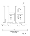
- FIG. 1 shows a read/write head 100 having a writer portion 102 and a reader portion 104.
- the writer portion 102 includes a writer and a coil or set of coils positioned around and/or near the writer.
- the coil or coils can be planar (as shown) or helical (sometimes called pancake coils), where the coil wraps around a back via.
- a heating circuit 106 is positioned near the writer portion 102.
- the circuit 106 When current is passed through the heating circuit 106, the circuit 106 provides localized heat to induce thermal protrusion at an air bearing surface (ABS).
- ABS air bearing surface
- An example of thermal protrusion along a down-track direction is shown as a dotted line in FIG. 1 , protruding towards recording media 108.
- the protrusion shape or profile is dependent on surrounding large volume shapes, such as write coils, which can be made with material having a high coefficient of thermal expansion, such as copper.
- Write coils' shapes impact the protrusion shape when write coils are heated by a heating element or by passing current through the write coils.
- Certain embodiments of the present disclosure are accordingly directed to systems, devices, and methods for shaping write coils to control protrusion shapes and the resulting contact area between a read/write transducer and the media.
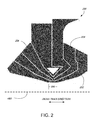
- FIG. 2 shows a portion of a helical write coil 200 having multiple coils turns 202-206.
- Coil turn 202 is positioned closest to an air bearing surface (ABS) and is followed by coil turns 204 and 206.
- the coil turns 202-206 are tapered to form a v-shape, which provides a narrow protrusion shape. As shown in FIG. 2 , the coil turns 202-206 become thinner as the coil gets closer to the ABS.
- Coil turn 202 includes a flat section 208 near the ABS. Adjusting a shape of the write coil 200 and its coil turns 202-206 can widen or narrow a protrusion shape in a cross-track direction. For example, adjusting the flat section's width will adjust a width of the protrusion in the cross-track direction.
- the protrusion shape can be tuned to be narrow, like the protrusion profile 600 shown in FIG. 6 - representing a protrusion shape induced from a write coil design similar to write coil 200 of FIG. 2 .
- a similar protrusion shape can be obtained by using multiple write coils. For example, instead of using a write coil having three coil turns, three individual write coils could be used.
- FIG. 3 shows a portion of a planar write coil 300 having multiple coil turns 302-306.
- Coil turn 302 is positioned closest to the ABS and is followed by coil turns 304 and 306.
- the coil turns are tapered near the ABS to form a v-shape, which provides a narrow protrusion shape.
- the coil turns 302-306 become thinner as the coil gets closer to the ABS.
- Coil turn 302 includes a flat section 308 near the ABS.
- Adjusting a shape of the write coil 300 and its coil turns 302-306 can widen or narrow a protrusion shape in a cross-track direction. For example, adjusting the flat section's width will adjust a width of the protrusion in the cross-track direction.
- a similar protrusion shape can be obtained by using multiple write coils. For example, instead of using a write coil having three coil turns, three individual write coils could be used.
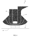
- FIG. 4 shows a portion of a helical write coil 400 having multiple coil turns 402-406.
- Coil turn 402 is positioned closest to the ABS and is followed by coil turns 404 and 406. The coil turns are tapered near the ABS to form a u-shape, which provides a broad protrusion shape.
- Coil turn 402 includes a flat section 408 near the ABS. The longer flat section 408 of FIG. 4 induces a broad profile, thereby widening a protrusion shape in the cross-direction. The wider shape provides additional contact area between a read/write head and recording medium.
- FIG. 6 shows a protrusion profile 602 induced from a write coil design similar to write coil 400 of FIG. 4 .
- a similar protrusion shape can be obtained by using multiple write coils. For example, instead of using a write coil having three coil turns, three individual write coils could be used.
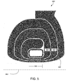
- FIG. 5 shows a portion of a planar write coil 500 having multiple coil turns 502-506.
- the coil turns are tapered near the ABS to form a u-shape, which provides a broad protrusion shape.
- Coil turn 502 includes a flat section 508 near the ABS.
- the longer flat section 508 of FIG. 5 induces a broad profile, thereby widening a protrusion shape in the cross-track direction.
- the wider shape provides additional contact area between a read/write head and recording medium.
- FIG. 6 provides a graph showing exemplary profiles 600, 602 of protrusion shapes induced by different write coil designs.
- Profile 600 represents a cross-track protrusion shape induced from a write coil design similar to that shown in FIG. 2 .
- Profile 600 has a sharper and narrower protrusion shape than profile 602, representing a cross-track protrusion shape induced from a write coil design similar to that shown in FIG. 4 . Similar protrusion shapes can be observed for the planar coil designs, respectively.
Landscapes
- Engineering & Computer Science (AREA)
- Chemical & Material Sciences (AREA)
- Combustion & Propulsion (AREA)
- Mechanical Engineering (AREA)
- General Engineering & Computer Science (AREA)
- Chemical Kinetics & Catalysis (AREA)
- General Chemical & Material Sciences (AREA)
- Oil, Petroleum & Natural Gas (AREA)
- Manufacturing & Machinery (AREA)
- Magnetic Heads (AREA)
- Coils Or Transformers For Communication (AREA)
Abstract
Description
- Certain embodiments of the present disclosure are generally directed to methods and devices including read/write heads with shaped write coils.
- In certain embodiments, a head includes a write coil having multiple coil turns. A portion of the multiple coil turns are positioned near an air bearing surface and form a v- or u-shape.
- In certain embodiments, a head includes a write coil having multiple coil turns. The coil turns closets to an air bearing surface are tapered.
-
-
FIG. 1 provides a side view of a portion of a read/write head, in accordance with certain embodiments of the present disclosure. -
FIG. 2 provides a view of a portion of a write coil, in accordance with certain embodiments of the present disclosure. -
FIG. 3 provides a view of a portion of a write coil, in accordance with certain embodiments of the present disclosure. -
FIG. 4 provides a view of a portion of a write coil, in accordance with certain embodiments of the present disclosure. -
FIG. 5 provides a view of a portion of a write coil, in accordance with certain embodiments of the present disclosure. -
FIG. 6 provides a graph of protrusion profiles, in accordance with certain embodiments of the present disclosure. - The present disclosure relates to devices, systems, and methods including write coils for read/write heads. By adjusting a write coil's shape, a protrusion profile of a read/write head's media-facing surface can be adjusted.
- During operation of a data storage device, read/write heads are positioned in close proximity to recording media to read and write data to the media. To control a distance between a head's reader or writer and the media, heads can include one or more heating circuits to induce thermal protrusion.
FIG. 1 shows a read/writehead 100 having awriter portion 102 and areader portion 104. Thewriter portion 102 includes a writer and a coil or set of coils positioned around and/or near the writer. The coil or coils can be planar (as shown) or helical (sometimes called pancake coils), where the coil wraps around a back via. Aheating circuit 106 is positioned near thewriter portion 102. When current is passed through theheating circuit 106, thecircuit 106 provides localized heat to induce thermal protrusion at an air bearing surface (ABS). An example of thermal protrusion along a down-track direction is shown as a dotted line inFIG. 1 , protruding towardsrecording media 108. - When using a heating element, the protrusion shape or profile is dependent on surrounding large volume shapes, such as write coils, which can be made with material having a high coefficient of thermal expansion, such as copper. Write coils' shapes impact the protrusion shape when write coils are heated by a heating element or by passing current through the write coils. Certain embodiments of the present disclosure are accordingly directed to systems, devices, and methods for shaping write coils to control protrusion shapes and the resulting contact area between a read/write transducer and the media.
-
FIG. 2 shows a portion of ahelical write coil 200 having multiple coils turns 202-206.Coil turn 202 is positioned closest to an air bearing surface (ABS) and is followed bycoil turns FIG. 2 , the coil turns 202-206 become thinner as the coil gets closer to the ABS.Coil turn 202 includes aflat section 208 near the ABS. Adjusting a shape of thewrite coil 200 and its coil turns 202-206 can widen or narrow a protrusion shape in a cross-track direction. For example, adjusting the flat section's width will adjust a width of the protrusion in the cross-track direction. The wider theflat section 208, the wider the protrusion and resulting contact area between a read/write head and recording medium. Therefore, the protrusion shape can be tuned to be narrow, like theprotrusion profile 600 shown inFIG. 6 - representing a protrusion shape induced from a write coil design similar to writecoil 200 ofFIG. 2 . Although the above description refers to a single write coil being used, a similar protrusion shape can be obtained by using multiple write coils. For example, instead of using a write coil having three coil turns, three individual write coils could be used. -
FIG. 3 shows a portion of aplanar write coil 300 having multiple coil turns 302-306.Coil turn 302 is positioned closest to the ABS and is followed bycoil turns FIG. 3 , the coil turns 302-306 become thinner as the coil gets closer to the ABS.Coil turn 302 includes aflat section 308 near the ABS. Adjusting a shape of thewrite coil 300 and its coil turns 302-306 can widen or narrow a protrusion shape in a cross-track direction. For example, adjusting the flat section's width will adjust a width of the protrusion in the cross-track direction. Although the above description refers to a single write coil being used, a similar protrusion shape can be obtained by using multiple write coils. For example, instead of using a write coil having three coil turns, three individual write coils could be used. -
FIG. 4 shows a portion of ahelical write coil 400 having multiple coil turns 402-406.Coil turn 402 is positioned closest to the ABS and is followed by coil turns 404 and 406. The coil turns are tapered near the ABS to form a u-shape, which provides a broad protrusion shape.Coil turn 402 includes aflat section 408 near the ABS. The longerflat section 408 ofFIG. 4 induces a broad profile, thereby widening a protrusion shape in the cross-direction. The wider shape provides additional contact area between a read/write head and recording medium.FIG. 6 shows aprotrusion profile 602 induced from a write coil design similar to writecoil 400 ofFIG. 4 . Although the above description refers to a single write coil being used, a similar protrusion shape can be obtained by using multiple write coils. For example, instead of using a write coil having three coil turns, three individual write coils could be used. -
FIG. 5 shows a portion of aplanar write coil 500 having multiple coil turns 502-506. The coil turns are tapered near the ABS to form a u-shape, which provides a broad protrusion shape.Coil turn 502 includes aflat section 508 near the ABS. The longerflat section 508 ofFIG. 5 induces a broad profile, thereby widening a protrusion shape in the cross-track direction. The wider shape provides additional contact area between a read/write head and recording medium. Although the above description refers to a single write coil being used, a similar protrusion shape can be obtained by using multiple write coils. For example, instead of using a write coil having three coil turns, three individual write coils could be used. -
FIG. 6 provides a graph showingexemplary profiles Profile 600 represents a cross-track protrusion shape induced from a write coil design similar to that shown inFIG. 2 .Profile 600 has a sharper and narrower protrusion shape thanprofile 602, representing a cross-track protrusion shape induced from a write coil design similar to that shown inFIG. 4 . Similar protrusion shapes can be observed for the planar coil designs, respectively. - It is to be understood that even though numerous characteristics and advantages of various embodiments of the present invention have been set forth in the foregoing description, together with details of the structure and function of various embodiments of the invention, this detailed description is illustrative only, and changes may be made in detail, especially in matters of structure and arrangements of parts within the principles of the present invention to the full extent indicated by the broad general meaning of the terms in which the appended claims are expressed.
Claims (10)
- A head (100) comprising:a write coil (200, 300) having multiple coil turns (202-206, 302-306), wherein a portion (202, 302) of the multiple coil turns are positioned near an air bearing surface (ABS) and form a v-shape.
- The head of claim 1, wherein the write coil (200) is a helical coil configuration.
- The head of claim 1, wherein the write coil (300) is a planar coil configuration.
- The head of any one of the preceding claims, wherein the write coil is positioned near a writer (102).
- The head of any one of the preceding claims, wherein the write coil is positioned near a reader (104).
- The head of any one of the preceding claims, wherein a coil turn closest to the air bearing surface has a flat section (208, 308) adjacent the air bearing surface.
- The head of any one of the preceding claims, wherein the write coil is tapered to for the v-shape.
- The head of any one of the preceding claims, wherein the v-shape induces a narrow protrusion profile.
- A head (100) comprising:a write coil (500) having multiple coil turns (502-506) in a planar coil configuration, wherein a portion of the multiple coil turns (506) are positioned near an air bearing surface (ABS) and form a u-shape.
- The head of claim 9, wherein a coil turn closest to the air bearing surface has a flat section (508) adjacent the air bearing surface.
Applications Claiming Priority (1)
| Application Number | Priority Date | Filing Date | Title |
|---|---|---|---|
| US13/357,701 US20130188281A1 (en) | 2012-01-25 | 2012-01-25 | Devices including shaped write coils |
Publications (1)
| Publication Number | Publication Date |
|---|---|
| EP2620942A1 true EP2620942A1 (en) | 2013-07-31 |
Family
ID=47740779
Family Applications (1)
| Application Number | Title | Priority Date | Filing Date |
|---|---|---|---|
| EP13152426.6A Withdrawn EP2620942A1 (en) | 2012-01-25 | 2013-01-23 | Devices including shaped write coils |
Country Status (5)
| Country | Link |
|---|---|
| US (1) | US20130188281A1 (en) |
| EP (1) | EP2620942A1 (en) |
| JP (1) | JP2013152776A (en) |
| KR (1) | KR20130086555A (en) |
| CN (1) | CN103226953A (en) |
Cited By (1)
| Publication number | Priority date | Publication date | Assignee | Title |
|---|---|---|---|---|
| US11631425B1 (en) * | 2022-01-14 | 2023-04-18 | Seagate Technology Llc | Magnetic storage writer with non-uniform coil thickness |
Citations (3)
| Publication number | Priority date | Publication date | Assignee | Title |
|---|---|---|---|---|
| US20050073773A1 (en) * | 2003-01-30 | 2005-04-07 | Headway Technologies, Inc. | Thin-film magnetic head and method of manufacturing same |
| US20060087770A1 (en) * | 2004-10-27 | 2006-04-27 | Hitachi Global Storage Technologies Netherlands B.V. | Magnetic recording head for perpendicular recording, fabrication process, and magnetic disk storage apparatus mounting the magnetic recording head |
| US20060285248A1 (en) * | 2005-06-16 | 2006-12-21 | Seagate Technology Llc | Writer heater for recording heads |
Family Cites Families (14)
| Publication number | Priority date | Publication date | Assignee | Title |
|---|---|---|---|---|
| US4160315A (en) * | 1978-04-17 | 1979-07-10 | Tandon Magnetics Corporation | Method of making a magnetic head assembly |
| US4698711A (en) * | 1985-10-02 | 1987-10-06 | International Business Machines Corporation | Simplified, shielded twin-track read/write head structure |
| JPH04192104A (en) * | 1990-11-27 | 1992-07-10 | Hitachi Ltd | Thin-film magnetic head |
| US5270887A (en) * | 1991-12-04 | 1993-12-14 | Western Digital Corporation | Compact disk drive head disk assembly with conformable tape seal |
| JPH05250636A (en) * | 1992-03-04 | 1993-09-28 | Hitachi Metals Ltd | Thin-film magnetic head |
| EP0650628B1 (en) * | 1992-07-17 | 1997-09-24 | Ampex Systems Corporation | Composite metal and ferrite head transducer and manufacturing method therefor |
| US6972932B2 (en) * | 2000-09-06 | 2005-12-06 | Seagate Technology Llc | High-efficiency single-turn write head for high-speed recording |
| US7227727B2 (en) * | 2003-05-07 | 2007-06-05 | Hitachi Global Storage Technologies Netherlands B.V. | Method and apparatus for a side-by-side thin film head with minimal separation between the read and write structures |
| JP2005063623A (en) * | 2003-08-20 | 2005-03-10 | Fuji Photo Film Co Ltd | Servo writer and servo writing method |
| US7119989B2 (en) * | 2004-02-20 | 2006-10-10 | Headway Technologies, Inc. | Thin-film magnetic head, method of manufacturing the same, head gimbal assembly, and hard disk drive |
| JP4095623B2 (en) * | 2005-04-05 | 2008-06-04 | 株式会社日立製作所 | Head for magneto-optical fusion recording apparatus and method for manufacturing the same |
| US7612963B2 (en) * | 2006-06-30 | 2009-11-03 | Hitachi Global Storage Technologies Netherlands B.V. | Perpendicular magnetic recording head with photoresist dam between write coil and air bearing surface |
| JP2008027504A (en) * | 2006-07-20 | 2008-02-07 | Fujitsu Ltd | Magnetic head |
| JP2008041115A (en) * | 2006-08-01 | 2008-02-21 | Alps Electric Co Ltd | Vertical magnetic recording head |
-
2012
- 2012-01-25 US US13/357,701 patent/US20130188281A1/en not_active Abandoned
-
2013
- 2013-01-22 KR KR1020130007060A patent/KR20130086555A/en not_active Ceased
- 2013-01-23 EP EP13152426.6A patent/EP2620942A1/en not_active Withdrawn
- 2013-01-24 CN CN2013100277679A patent/CN103226953A/en active Pending
- 2013-01-24 JP JP2013011195A patent/JP2013152776A/en active Pending
Patent Citations (3)
| Publication number | Priority date | Publication date | Assignee | Title |
|---|---|---|---|---|
| US20050073773A1 (en) * | 2003-01-30 | 2005-04-07 | Headway Technologies, Inc. | Thin-film magnetic head and method of manufacturing same |
| US20060087770A1 (en) * | 2004-10-27 | 2006-04-27 | Hitachi Global Storage Technologies Netherlands B.V. | Magnetic recording head for perpendicular recording, fabrication process, and magnetic disk storage apparatus mounting the magnetic recording head |
| US20060285248A1 (en) * | 2005-06-16 | 2006-12-21 | Seagate Technology Llc | Writer heater for recording heads |
Cited By (1)
| Publication number | Priority date | Publication date | Assignee | Title |
|---|---|---|---|---|
| US11631425B1 (en) * | 2022-01-14 | 2023-04-18 | Seagate Technology Llc | Magnetic storage writer with non-uniform coil thickness |
Also Published As
| Publication number | Publication date |
|---|---|
| KR20130086555A (en) | 2013-08-02 |
| JP2013152776A (en) | 2013-08-08 |
| US20130188281A1 (en) | 2013-07-25 |
| CN103226953A (en) | 2013-07-31 |
Similar Documents
| Publication | Publication Date | Title |
|---|---|---|
| US8665561B1 (en) | Method and system for providing enhanced thermal expansion for hard disk drives | |
| US8310787B1 (en) | Thin-film magnetic head, method of manufacturing the same, head gimbal assembly, and hard disk drive | |
| US8149541B2 (en) | System for controlling contact location during TFC touchdown and methods thereof | |
| US7573682B2 (en) | Writer heater for thermal protrusion shape control in a magnetic writer | |
| US8335053B2 (en) | Integrated touch-down pad and touch-down sensor | |
| US8576514B2 (en) | Thin-film magnetic head, method of manufacturing the same, head gimbal assembly, and hard disk drive | |
| US8687318B2 (en) | Recording head coil structure | |
| US8390955B1 (en) | Thin-film magnetic head, method of manufacturing the same, head gimbal assembly, and hard disk drive | |
| US8760808B2 (en) | Magnetic device containing a heater | |
| US9202497B2 (en) | Adjusting a clearance between a magnetic head and a magnetic recording medium using a magnetic force | |
| US9324351B2 (en) | Contact pad for recording heads | |
| US8681446B2 (en) | Methods and devices including multiple resistive heating elements | |
| US20130188281A1 (en) | Devices including shaped write coils | |
| US10366715B1 (en) | Slider with heat sink between read transducer and substrate | |
| US8514520B2 (en) | Perpendicular magnetic recording head including a front shield part and the method of manufacturing the same | |
| US9368139B1 (en) | Slider back side etching to increase shear strength between suspension and slider | |
| US8499435B2 (en) | Method of manufacturing a thin-film magnetic head | |
| US9324341B2 (en) | Magnetic head for perpendicular magnetic recording including a heater | |
| GB2502194A (en) | Excitation of air bearing oscillation with TAR near field device for touchdown detection | |
| US8837083B1 (en) | Magnetic head for perpendicular magnetic recording including a heater | |
| US8514516B2 (en) | Thin-film magnetic head, method of manufacturing the same, head gimbal assembly, and hard disk drive | |
| US9171556B2 (en) | Magnetic head including two contact sensors | |
| Knigge et al. | Friction and heat at the head disk interface caused by thermal protrusion touchdown |
Legal Events
| Date | Code | Title | Description |
|---|---|---|---|
| PUAI | Public reference made under article 153(3) epc to a published international application that has entered the european phase |
Free format text: ORIGINAL CODE: 0009012 |
|
| 17P | Request for examination filed |
Effective date: 20130214 |
|
| AK | Designated contracting states |
Kind code of ref document: A1 Designated state(s): AL AT BE BG CH CY CZ DE DK EE ES FI FR GB GR HR HU IE IS IT LI LT LU LV MC MK MT NL NO PL PT RO RS SE SI SK SM TR |
|
| AX | Request for extension of the european patent |
Extension state: BA ME |
|
| RBV | Designated contracting states (corrected) |
Designated state(s): AL AT BE BG CH CY CZ DE DK EE ES FI FR GB GR HR HU IE IS IT LI LT LU LV MC MK MT NL NO PL PT RO RS SE SI SK SM TR |
|
| STAA | Information on the status of an ep patent application or granted ep patent |
Free format text: STATUS: THE APPLICATION IS DEEMED TO BE WITHDRAWN |
|
| 18D | Application deemed to be withdrawn |
Effective date: 20140201 |