EP2620767A1 - Cell analyzer - Google Patents
Cell analyzer Download PDFInfo
- Publication number
- EP2620767A1 EP2620767A1 EP11826549.5A EP11826549A EP2620767A1 EP 2620767 A1 EP2620767 A1 EP 2620767A1 EP 11826549 A EP11826549 A EP 11826549A EP 2620767 A1 EP2620767 A1 EP 2620767A1
- Authority
- EP
- European Patent Office
- Prior art keywords
- dispersion
- unit
- specimen
- dispersion process
- cells
- Prior art date
- Legal status (The legal status is an assumption and is not a legal conclusion. Google has not performed a legal analysis and makes no representation as to the accuracy of the status listed.)
- Granted
Links
Images




Classifications
-
- G—PHYSICS
- G01—MEASURING; TESTING
- G01N—INVESTIGATING OR ANALYSING MATERIALS BY DETERMINING THEIR CHEMICAL OR PHYSICAL PROPERTIES
- G01N21/00—Investigating or analysing materials by the use of optical means, i.e. using sub-millimetre waves, infrared, visible or ultraviolet light
- G01N21/17—Systems in which incident light is modified in accordance with the properties of the material investigated
- G01N21/47—Scattering, i.e. diffuse reflection
- G01N21/4738—Diffuse reflection, e.g. also for testing fluids, fibrous materials
-
- G—PHYSICS
- G01—MEASURING; TESTING
- G01N—INVESTIGATING OR ANALYSING MATERIALS BY DETERMINING THEIR CHEMICAL OR PHYSICAL PROPERTIES
- G01N1/00—Sampling; Preparing specimens for investigation
- G01N1/28—Preparing specimens for investigation including physical details of (bio-)chemical methods covered elsewhere, e.g. G01N33/50, C12Q
- G01N1/38—Diluting, dispersing or mixing samples
-
- C—CHEMISTRY; METALLURGY
- C12—BIOCHEMISTRY; BEER; SPIRITS; WINE; VINEGAR; MICROBIOLOGY; ENZYMOLOGY; MUTATION OR GENETIC ENGINEERING
- C12Q—MEASURING OR TESTING PROCESSES INVOLVING ENZYMES, NUCLEIC ACIDS OR MICROORGANISMS; COMPOSITIONS OR TEST PAPERS THEREFOR; PROCESSES OF PREPARING SUCH COMPOSITIONS; CONDITION-RESPONSIVE CONTROL IN MICROBIOLOGICAL OR ENZYMOLOGICAL PROCESSES
- C12Q1/00—Measuring or testing processes involving enzymes, nucleic acids or microorganisms; Compositions therefor; Processes of preparing such compositions
-
- G—PHYSICS
- G01—MEASURING; TESTING
- G01N—INVESTIGATING OR ANALYSING MATERIALS BY DETERMINING THEIR CHEMICAL OR PHYSICAL PROPERTIES
- G01N15/00—Investigating characteristics of particles; Investigating permeability, pore-volume or surface-area of porous materials
- G01N15/10—Investigating individual particles
- G01N15/14—Optical investigation techniques, e.g. flow cytometry
-
- G—PHYSICS
- G01—MEASURING; TESTING
- G01N—INVESTIGATING OR ANALYSING MATERIALS BY DETERMINING THEIR CHEMICAL OR PHYSICAL PROPERTIES
- G01N21/00—Investigating or analysing materials by the use of optical means, i.e. using sub-millimetre waves, infrared, visible or ultraviolet light
- G01N21/17—Systems in which incident light is modified in accordance with the properties of the material investigated
- G01N21/47—Scattering, i.e. diffuse reflection
-
- G—PHYSICS
- G01—MEASURING; TESTING
- G01N—INVESTIGATING OR ANALYSING MATERIALS BY DETERMINING THEIR CHEMICAL OR PHYSICAL PROPERTIES
- G01N33/00—Investigating or analysing materials by specific methods not covered by groups G01N1/00 - G01N31/00
- G01N33/48—Biological material, e.g. blood, urine; Haemocytometers
- G01N33/50—Chemical analysis of biological material, e.g. blood, urine; Testing involving biospecific ligand binding methods; Immunological testing
- G01N33/53—Immunoassay; Biospecific binding assay; Materials therefor
- G01N33/536—Immunoassay; Biospecific binding assay; Materials therefor with immune complex formed in liquid phase
- G01N33/542—Immunoassay; Biospecific binding assay; Materials therefor with immune complex formed in liquid phase with steric inhibition or signal modification, e.g. fluorescent quenching
-
- G—PHYSICS
- G01—MEASURING; TESTING
- G01N—INVESTIGATING OR ANALYSING MATERIALS BY DETERMINING THEIR CHEMICAL OR PHYSICAL PROPERTIES
- G01N1/00—Sampling; Preparing specimens for investigation
- G01N1/28—Preparing specimens for investigation including physical details of (bio-)chemical methods covered elsewhere, e.g. G01N33/50, C12Q
- G01N1/286—Preparing specimens for investigation including physical details of (bio-)chemical methods covered elsewhere, e.g. G01N33/50, C12Q involving mechanical work, e.g. chopping, disintegrating, compacting, homogenising
-
- G—PHYSICS
- G01—MEASURING; TESTING
- G01N—INVESTIGATING OR ANALYSING MATERIALS BY DETERMINING THEIR CHEMICAL OR PHYSICAL PROPERTIES
- G01N21/00—Investigating or analysing materials by the use of optical means, i.e. using sub-millimetre waves, infrared, visible or ultraviolet light
- G01N21/17—Systems in which incident light is modified in accordance with the properties of the material investigated
- G01N21/47—Scattering, i.e. diffuse reflection
- G01N2021/4704—Angular selective
- G01N2021/4707—Forward scatter; Low angle scatter
-
- G—PHYSICS
- G01—MEASURING; TESTING
- G01N—INVESTIGATING OR ANALYSING MATERIALS BY DETERMINING THEIR CHEMICAL OR PHYSICAL PROPERTIES
- G01N21/00—Investigating or analysing materials by the use of optical means, i.e. using sub-millimetre waves, infrared, visible or ultraviolet light
- G01N21/17—Systems in which incident light is modified in accordance with the properties of the material investigated
- G01N21/47—Scattering, i.e. diffuse reflection
- G01N2021/4704—Angular selective
- G01N2021/4726—Detecting scatter at 90°
-
- G—PHYSICS
- G01—MEASURING; TESTING
- G01N—INVESTIGATING OR ANALYSING MATERIALS BY DETERMINING THEIR CHEMICAL OR PHYSICAL PROPERTIES
- G01N21/00—Investigating or analysing materials by the use of optical means, i.e. using sub-millimetre waves, infrared, visible or ultraviolet light
- G01N21/62—Systems in which the material investigated is excited whereby it emits light or causes a change in wavelength of the incident light
- G01N21/63—Systems in which the material investigated is excited whereby it emits light or causes a change in wavelength of the incident light optically excited
- G01N21/64—Fluorescence; Phosphorescence
- G01N21/6428—Measuring fluorescence of fluorescent products of reactions or of fluorochrome labelled reactive substances, e.g. measuring quenching effects, using measuring "optrodes"
- G01N2021/6439—Measuring fluorescence of fluorescent products of reactions or of fluorochrome labelled reactive substances, e.g. measuring quenching effects, using measuring "optrodes" with indicators, stains, dyes, tags, labels, marks
-
- G—PHYSICS
- G01—MEASURING; TESTING
- G01N—INVESTIGATING OR ANALYSING MATERIALS BY DETERMINING THEIR CHEMICAL OR PHYSICAL PROPERTIES
- G01N35/00—Automatic analysis not limited to methods or materials provided for in any single one of groups G01N1/00 - G01N33/00; Handling materials therefor
- G01N2035/00346—Heating or cooling arrangements
- G01N2035/00356—Holding samples at elevated temperature (incubation)
-
- G—PHYSICS
- G01—MEASURING; TESTING
- G01N—INVESTIGATING OR ANALYSING MATERIALS BY DETERMINING THEIR CHEMICAL OR PHYSICAL PROPERTIES
- G01N35/00—Automatic analysis not limited to methods or materials provided for in any single one of groups G01N1/00 - G01N33/00; Handling materials therefor
- G01N2035/00465—Separating and mixing arrangements
- G01N2035/00534—Mixing by a special element, e.g. stirrer
- G01N2035/00554—Mixing by a special element, e.g. stirrer using ultrasound
-
- G—PHYSICS
- G01—MEASURING; TESTING
- G01N—INVESTIGATING OR ANALYSING MATERIALS BY DETERMINING THEIR CHEMICAL OR PHYSICAL PROPERTIES
- G01N21/00—Investigating or analysing materials by the use of optical means, i.e. using sub-millimetre waves, infrared, visible or ultraviolet light
- G01N21/62—Systems in which the material investigated is excited whereby it emits light or causes a change in wavelength of the incident light
- G01N21/63—Systems in which the material investigated is excited whereby it emits light or causes a change in wavelength of the incident light optically excited
- G01N21/64—Fluorescence; Phosphorescence
- G01N21/6428—Measuring fluorescence of fluorescent products of reactions or of fluorochrome labelled reactive substances, e.g. measuring quenching effects, using measuring "optrodes"
-
- G—PHYSICS
- G01—MEASURING; TESTING
- G01N—INVESTIGATING OR ANALYSING MATERIALS BY DETERMINING THEIR CHEMICAL OR PHYSICAL PROPERTIES
- G01N35/00—Automatic analysis not limited to methods or materials provided for in any single one of groups G01N1/00 - G01N33/00; Handling materials therefor
- G01N35/02—Automatic analysis not limited to methods or materials provided for in any single one of groups G01N1/00 - G01N33/00; Handling materials therefor using a plurality of sample containers moved by a conveyor system past one or more treatment or analysis stations
- G01N35/025—Automatic analysis not limited to methods or materials provided for in any single one of groups G01N1/00 - G01N33/00; Handling materials therefor using a plurality of sample containers moved by a conveyor system past one or more treatment or analysis stations having a carousel or turntable for reaction cells or cuvettes
Definitions
- a cell analyzer is a cell analyzer including: a cell dispersion unit which causes aggregated cells in a biological specimen to be dispersed, through a first dispersion process and a second dispersion process which is different from the first dispersion process; a detection unit which detects characteristics information reflecting properties of the cells in the biological specimen on which the first dispersion process and the second dispersion process have been performed; and an analysis unit which analyzes the cells in the biological specimen, based on a detection result from the detection unit.
- the measuring apparatus 2 includes a primary detection unit 21, a signal processing unit 22, a measurement control unit 23, and an I/O interface 24. Further, the measuring apparatus 2 includes a supplementary detection unit 31, a signal processing unit 32, a preparation control unit 33, and a preparation device unit 35 for automatically adjusting components for a biological specimen.
- the container transfer unit 54 has a function of holding a measurement specimen container 7 which an user has set in the reaction unit 57, between scissors-shaped grippers 54a; and transferring the measurement specimen container 7 to each of the specimen relaying part 52b, the second dispersion unit 55, the liquid removing unit 56, and the reaction unit 57.
- the container transfer unit 54 is configured to move the grippers 54a along a circular path C about a predetermined rotation center. Further, the container transfer unit 54 is configured to be able to move the grippers 54a in the up-down direction. It should be noted that the specimen relaying part 52b, the second dispersion unit 55, the liquid removing unit 56, and the reaction unit 57 are arranged on this circular path C. This allows the grippers 54a of the container transfer unit 54 to hold and transfer a measurement specimen container 7 which the user has set in the reaction unit 57, to each of the components arranged along the circular path C.
- the specimen aspirating unit 59 is connected to a flow cell 13 described later (see FIGS. 5 and 6 ) of the primary detection unit 21 via a flow channel (not shown), and is configured to be able to supply the measurement specimen aspirated by the pipette 59a to the flow cell 13 of the primary detection unit 21.
- the biological specimen is aspirated by the specimen aspirating unit 59 after the processes by the first reagent adding unit 58a and the second reagent adding unit 58b, without any other process interposed therebetween. Therefore, it is configured such that detection by the primary detection unit 21 is performed immediately after the processes by the first reagent adding unit 58a and the second reagent adding unit 58b have been completed.
- the microprocessor 36 of the preparation control unit 33 is connected to the microprocessor 25 of the measurement control unit 23 via the I/O interface 24. Accordingly, the microprocessor 36 can transmit and receive various types of data to and from the microprocessor 25 of the measurement control unit 23.
- each projecting part 64 which extend in a direction (radial direction) orthogonal to the rotational direction (arrow R direction) of the rotor 70 when seen in a plan view, and which project toward the rotor 70 side (upward), are formed on the upper face of the bottom 62. Further, four liquid retaining parts 65 composed of recesses defined by these projecting parts 64 are formed in the upper face of the bottom 62. As shown in FIG. 11 , the thickness of the bottom 62 (each projecting part 64) is t1 (about 1 mm), and the depth of each liquid retaining part 65 is t2 (about 0.5 mm).
- the measurement specimen container 7 is immersed in the liquid 113 in the liquid holding chamber 111, while being griped by the grippers 54a of the container transfer unit 54.
- a lowered position of the container transfer unit 54 (the grippers 54a) is set such that the surface of the liquid in the measurement specimen container 7 is positioned lower than the surface of the liquid 113.
- the surface of the liquid in the measurement specimen container 7 is preferably positioned lower than the surface of the liquid 113 in the recess 114, by about 1 mm to 2 mm.
- step S7 the measurement specimen that has been subjected to the staining process is sent to the flow cell 13 of the primary detection unit 21, and the main measurement is performed on the cells in the measurement specimen.
- the measurement specimen container 7 is moved to the aspiration position P3 for the specimen aspirating unit 59 by the rotatable table 57a.
- the pipette 59a of the specimen aspirating unit 59 is moved to the aspiration position P3. Accordingly, the measurement specimen is aspirated by the pipette 59a of the specimen aspirating unit 59 immediately after the completion of the staining process, without any other process interposed therebetween.
- the second dispersion process is an ultrasonic dispersion process of dispersing aggregated cells, by using ultrasonic waves.
- ultrasonic waves can cause cavitation (formation and then immediate implosion of bubbles) in the biological specimen, to disperse aggregated cells. Since the bubbles generated by ultrasonic waves are fine, a uniform and scarcely-biased dispersion effect can be obtained, and damage to cells can also be suppressed during the dispersion processes.
- the sample pipetting unit 52 is configured to dispense the biological specimen in the specimen holding chamber 51a on which the first dispersion process has been performed, to a measurement specimen container 7; and the container transfer unit 54 is configured to transfer the measurement specimen container 7 containing the biological specimen dispensed by the sample pipetting unit 52, to the second dispersion unit 55.
- the sample pipetting unit 52 can dispense, into the measurement specimen container 7, the biological specimen only by the amount necessary for detection by the primary detection unit 21, and the second dispersion process can be efficiently performed only on the biological specimen dispensed in the measurement specimen container 7.
- the third dispersion unit 205 is configured to add the dispersion liquid in the measurement specimen container 7, after the second dispersion process by the second dispersion unit 55 has been performed, and then addition of the reagent (RNAse) by the first reagent adding unit 58a and addition of the reagent (stain solution) by the second reagent adding unit 58b have been performed, and immediately before the specimen is sent to the primary detection unit 21.
Landscapes
- Health & Medical Sciences (AREA)
- Chemical & Material Sciences (AREA)
- Life Sciences & Earth Sciences (AREA)
- Immunology (AREA)
- General Health & Medical Sciences (AREA)
- Biochemistry (AREA)
- Analytical Chemistry (AREA)
- Physics & Mathematics (AREA)
- Engineering & Computer Science (AREA)
- General Physics & Mathematics (AREA)
- Pathology (AREA)
- Organic Chemistry (AREA)
- Molecular Biology (AREA)
- Biotechnology (AREA)
- Urology & Nephrology (AREA)
- Microbiology (AREA)
- Proteomics, Peptides & Aminoacids (AREA)
- Hematology (AREA)
- Wood Science & Technology (AREA)
- Zoology (AREA)
- Biomedical Technology (AREA)
- Dispersion Chemistry (AREA)
- General Engineering & Computer Science (AREA)
- Genetics & Genomics (AREA)
- Bioinformatics & Cheminformatics (AREA)
- Cell Biology (AREA)
- Biophysics (AREA)
- Food Science & Technology (AREA)
- Medicinal Chemistry (AREA)
- Investigating Or Analysing Biological Materials (AREA)
- Apparatus Associated With Microorganisms And Enzymes (AREA)
Abstract
Description
- The present invention relates to cell analyzers, and in particular, to cell analyzers that analyze cells contained in a biological specimen collected from an organism.
- As a cell analyzer that analyzes cells contained in a biological specimen collected from an organism, there has been conventionally known a cell analyzer that screens cancer cells or atypical cells by measuring, with a flow cytometer, epithelial cells of the uterine cervix contained in a specimen collected from the uterine cervix of a subject (see Patent Literature 1, for example).
- The cell analyzer described in Patent Literature 1 above includes: a cell dispersion unit which actively causes aggregated cells of a biological specimen to be dispersed in a biological specimen container; a flow cytometer which perform studies of cells dispersed in a measurement specimen, which have been subjected to the dispersion process through the cell dispersion unit; and a data processing apparatus which analyzes measured data from the flow cytometer to determine whether or not cells in the specimen are cancerous.
-
- The cell analyzer described in Patent Literature 1 allows for a determination of whether or not cells in the measurement specimen are cancerous. However, cells highly aggregated in a biological specimen are not to be dispersed in an appropriate manner. This results in impaired degree of accuracy in the analysis. Therefore, it is desired that highly accurate cell analysis can be performed even when cells in a biological specimen are aggregated at a high level.
- In view of the above situation, an object of the present invention is to provide a cell analyzer that can perform highly accurate cell analysis even when cells in a biological specimen are aggregated at a high level.
- In order to attain the above object, a cell analyzer according to an aspect of the present invention is a cell analyzer including: a cell dispersion unit which causes aggregated cells in a biological specimen to be dispersed, through a first dispersion process and a second dispersion process which is different from the first dispersion process; a detection unit which detects characteristics information reflecting properties of the cells in the biological specimen on which the first dispersion process and the second dispersion process have been performed; and an analysis unit which analyzes the cells in the biological specimen, based on a detection result from the detection unit.
- As described above, the cell analyzer according to the aforesaid aspect of the present invention is provided with: the cell dispersion unit which performs, on the biological specimen, the first dispersion process and the second dispersion process which is different from the first dispersion process; the detection unit which detects characteristics information of predetermined cells contained in the biological specimen on which the first dispersion process and the second dispersion process have been performed; and the analysis unit which analyzes the predetermined cells based on the detection result. Accordingly, a plurality of dispersion processes of different types can be performed on the biological specimen. Therefore, even when cells in the biological specimen are aggregated at a high level, such cells can be effectively dispersed. Accordingly, even when cells are aggregated at a high level, the aggregated cells are sufficiently dispersed into single cells, and thus, highly accurate cell detection can be performed. As a result, even when the cells are aggregated at a high level, highly accurate cell analysis can be performed based on high-accurate detection results.
- Preferably, in the cell analyzer according to the aforesaid aspect, the cell dispersion unit includes a first dispersion unit which performs the first dispersion process, and a second dispersion unit which performs the second dispersion process. According to this configuration, by providing the first dispersion unit and the second dispersion unit, it is possible to easily obtain a configuration in which the first dispersion process and the second dispersion process, which are different from each other, are respectively performed.
- Preferably, the cell analyzer according to the aforesaid aspect includes: a supplementary detection unit which detects the cells in the biological specimen; and a specimen preparation unit which prepares, from the biological specimen, a measurement specimen to be subjected to detection by the detection unit, based on a detection result from the supplementary detection unit, and the cell dispersion unit is configured to perform at least one of the first dispersion process and the second dispersion process before detection by the supplementary detection unit is performed. According to this configuration, by preparing a measurement specimen based on the detection result from the supplementary detection unit, it is possible to prepare a measurement specimen suitable for detection to be performed by the detection unit. At this time, since at least one of the first dispersion process and the second dispersion process is performed before the detection by the supplementary detection unit, detection by the supplementary detection unit can be performed after aggregated cells have been dispersed to some extent. As a result, accuracy of the detection by the supplementary detection unit can be improved.
- Preferably, the cell analyzer according to the aforesaid aspect further includes a stain solution adding unit which adds a stain solution which stains the cells, to the biological specimen, and the stain solution adding unit is configured to add the stain solution to the biological specimen after the first dispersion process and the second dispersion process have been performed. According to this configuration, it is possible to stain the cells after the aggregated cells have been sufficiently dispersed into single cells through the first dispersion process and the second dispersion process. Thus, the dispersed individual cells can be assuredly stained by the stain solution.
- Preferably, in this case, the first dispersion process is a shearing force applying process of applying a shearing force to the aggregated cells, and the second dispersion process is an ultrasonic dispersion process of dispersing the aggregated cells, by using ultrasonic waves. According to this configuration, relatively large aggregated cells can be effectively dispersed through the shearing force applying process, and relatively small aggregated cells can be effectively dispersed through the ultrasonic dispersion process. Thus, it is possible to more assuredly stain the individual cells dispersed through the shearing force applying process and the ultrasonic dispersion process.
- Preferably, in the cell analyzer according to the aforesaid aspect, one of the first dispersion process and the second dispersion process is a shearing force applying process of applying a shearing force to the aggregated cells. According to this configuration, the aggregated cells can be forcibly dispersed with the shearing force, and thus, the aggregated cells can be efficiently dispersed also in the case of the biological specimen having a relatively large amount.
- Preferably, in the cell analyzer according to the aforesaid aspect, the first dispersion unit includes a specimen holding chamber which receives the biological specimen, a rotor, and a pipe which accommodates the rotor, an apertured member is attached to an opening at an end of the pipe, and an opening is provided in a side wall of the pipe, and the first dispersion unit causes the aggregated cells to be dispersed in the biological specimen, by rotating the rotor, with the rotor and the pipe inserted into the specimen holding chamber, and thus by circulating the biological specimen between an aperture provided in the apertured member and the opening in the side wall of the pipe.
- Preferably, in the cell analyzer according to the aforesaid aspect, one of the first dispersion process and the second dispersion process is an ultrasonic dispersion process of dispersing the aggregated cells , by using ultrasonic waves. According to this configuration, it is possible to cause cavitation (formation and then immediate implosion of bubbles) in the biological specimen through ultrasonic waves to disperse the aggregated cells. Since the bubbles generated with ultrasonic waves are fine, a uniform and scarcely-biased dispersion effect can be obtained. Thus, increase of damage of cells associated with the dispersion processes can also be suppressed.
- Preferably, in this case, the ultrasonic dispersion process, which is one of the first dispersion process and the second dispersion process, is configured to be performed on the biological specimen having an amount smaller than that of the biological specimen on which the other of the first dispersion process and the second dispersion process is performed. According to this configuration, the ultrasonic dispersion process can be performed on the biological specimen having a smaller amount, and thus, the ultrasonic dispersion apparatus can be downsized. The downsizing of the ultrasonic dispersion apparatus can reduce generation and the like of noises due to generation of ultrasonic waves. Further, by performing the ultrasonic dispersion process on the biological specimen having a smaller amount, ultrasonic vibrations can be easily and uniformly applied to the entire biological specimen, and thus, a high dispersion effect can be easily obtained.
- Preferably, in the cell analyzer according to the aforesaid aspect, the first dispersion process is a shearing force applying process of applying a shearing force to the cells that are aggregated, the second dispersion process is an ultrasonic dispersion process of dispersing the cells that are aggregated, by using ultrasonic waves, and the cell dispersion unit is configured to perform the second dispersion process after performing the first dispersion process. According to this configuration, even when the cells are aggregated at a high level, the aggregated cells can be forcibly dispersed with the shearing force, first. Thus, the aggregated cells can be efficiently dispersed. In addition, aggregated cells remaining after the shearing force applying process has been performed can be dispersed through the ultrasonic dispersion process. Thus, an efficient dispersion process can be performed.
- Preferably, in this case, the cell dispersion unit includes a first dispersion unit which performs the first dispersion process, and a second dispersion unit which performs the second dispersion process, the first dispersion unit includes a specimen holding chamber which receives the biological specimen, and performs the first dispersion process on the biological specimen received in the specimen holding chamber, and the cell analyzer includes: a specimen dispensing unit which dispenses, into a specimen container, the biological specimen in the specimen holding chamber on which the first dispersion process has been performed; and a container transfer unit which transfers, to the second dispersion unit, the specimen container containing the biological specimen dispensed by the specimen dispensing unit. According to this configuration, after the first dispersion process has been performed, the specimen dispensing unit can dispense the biological specimen having only the amount necessary for detection by the detection unit, into the specimen container. Thus, the second dispersion process can be efficiently performed only on the biological specimen dispensed into the specimen container.
- Preferably, in the configuration including the specimen dispensing unit and the container transfer unit, the second dispersion unit includes a liquid holding chamber for receiving a liquid to be subjected to ultrasonic waves, and the container transfer unit is configured to grip and transfer the specimen container, and is configured to immerse the specimen container in the liquid received in the liquid holding chamber, while gripping the specimen container containing the biological specimen dispensed by the specimen dispensing unit. According to this configuration, the second dispersion process (ultrasonic dispersion process) can be performed while the biological specimen is contained in the specimen container, without aspirating/discharging the biological specimen from/into the specimen container. This eliminates the necessity of steps of aspirating and discharging the biological specimen, and thus, the time necessary for the second dispersion process can be shortened. Therefore, it is possible to suppress increase of damage on the cells to be measured before they are subjected to the detection by the detection unit.
- Preferably, in the cell analyzer according to the aforesaid aspect, one of the first dispersion process and the second dispersion process is a dispersion liquid adding process of adding a dispersion liquid to the biological specimen to disperse the aggregated cells.
According to this configuration, the aggregated cells can be chemically dispersed into single cells, through addition of the dispersion liquid. - Preferably, in this case, the dispersion liquid is a surfactant. According to this configuration, the aggregated cells can be effectively dispersed through addition of the surfactant.
- Preferably, in the cell analyzer according to the aforesaid aspect, the detection unit includes a flow cell which allows the biological specimen to pass therethrough, a light source part which emits light to the biological specimen passing through the flow cell, and a light receiver which receives lights generated by the light source part emitting light on the biological specimen. This configuration allows for improved detection accuracy in flow cytometry since the first and the second dispersion processes cause effectively cells to be dispersed, and to be individually subjected to flow cytometry.
- Preferably, in the cell analyzer according to the aforesaid aspect, the cells are epithelial cells, and the analysis unit is configured to analyze whether the epithelial cells in the detection are atypical. According to this configuration, it is possible to obtain an analyzer for detecting cancer cells (or atypical epithelial cells) that can perform highly accurate cell detection irrespective of the aggregation level of the epithelial cells in the biological specimen, by performing a plurality of dispersion processes of different types on the biological specimen.
-
- [
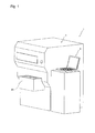
FIG. 1] FIG. 1 is a perspective view showing an overall structure of a cell analyzer according to a first embodiment of the present invention. - [
FIG 2] FIG. 2 is a block diagram showing a configuration of a measuring apparatus of the cell analyzer shown inFIG. 1 . - [
FIG. 3] FIG. 3 is a schematic diagram showing an arrangement, seen in a plan view, of components of the measuring apparatus shown inFIG. 2 . - [
FIG. 4] FIG. 4 is a block diagram showing a configuration of a data processing apparatus of the cell analyzer shown inFIG. 1 . - [
FIG. 5] FIG. 5 is a schematic diagram showing a flow cytometer forming a primary detection unit of the measuring apparatus shown inFIG. 2 . - [
FIG. 6] FIG. 6 is a schematic diagram showing an optical system of the flow cytometer shown inFIG. 5 . - [
FIG. 7] FIG. 7 is a perspective view showing an overall structure of a first dispersion unit of the measuring apparatus shown inFIG. 3 . - [
FIG. 8] FIG. 8 is a longitudinal sectional view of the first dispersion unit shown inFIG. 7 . - [
FIG. 9] FIG. 9 is a perspective view showing an apertured member of the first dispersion unit shown inFIG. 7 . - [
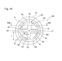
FIG. 10] FIG. 10 is a top view of the apertured member shown inFIG. 9 . - [
FIG. 11] FIG. 11 is a cross-sectional view of the apertured member cut along the line 500-500 inFIG. 10 . - [
FIG. 12] FIG. 12 is a side view showing a rotor of the first dispersion unit shown inFIG. 7 . - [
FIG. 13] FIG. 13 is a bottom view of the rotor shown inFIG. 12 . - [
FIG. 14] FIG. 14 is a schematic diagram for explaining operations performed by the first dispersion unit shown inFIG. 7 . - [
FIG. 15] FIG. 15 is a cross-sectional view schematically showing an overall structure of a second dispersion unit of the measuring apparatus shown inFIG. 3 . - [
FIG. 16] FIG. 16 is a flow chart for explaining analysis operation performed by the cell analyzer according to the first embodiment of the present invention. - [
FIG. 17] FIG. 17 is a schematic diagram showing an arrangement, seen in a plan view, of components of the measuring apparatus of the cell analyzer according to a second embodiment of the present invention. - Hereinafter, specific embodiments of the present invention will be described with reference to the drawings.
- First, with reference to
FIGS. 1 to 15 , a configuration of a cell analyzer 1 according to a first embodiment of the present invention will be described. - The cell analyzer 1 causes a measurement specimen containing cells collected from a patient, to flow through a flow cell; and the analyzer emits a beam of laser right onto the measurement specimen streaming through the flow cell. Then, the analyzer detects lights (forward scattered light, side fluorescence, etc.) from the measurement specimen, analyzes the light signals and determines whether or not cancer cells are included in the cells. More specifically, the cell analyzer 1 according to the first embodiment targets epithelial cells of the uterine cervix as its analyte, and is used for screening cervical cancer.
- As shown in
FIG. 1 , the cell analyzer 1 includes: a measuringapparatus 2 which applies a cell dispersion process, a staining process, etc. to a biological specimen collected from the uterine cervix of a subject to prepare a measurement specimen, and which also performs optical measurement on the measurement specimen using a laser beam; and adata processing apparatus 4 which analyzes measurement results obtained through the measuringapparatus 2. - As shown in
FIG. 2 , the measuringapparatus 2 includes aprimary detection unit 21, asignal processing unit 22, ameasurement control unit 23, and an I/O interface 24. Further, the measuringapparatus 2 includes asupplementary detection unit 31, asignal processing unit 32, apreparation control unit 33, and apreparation device unit 35 for automatically adjusting components for a biological specimen. - The
primary detection unit 21 has a function of detecting target cells (cervical uterine epithelial cells) in the measurement specimen, the number of and the size of each of, the cells and nuclei therein, and the like. In the first embodiment, theprimary detection unit 21 employs aflow cytometer 10 as shown inFIGS. 5 and6 . - The
signal processing unit 22 includes a signal processing circuit that performs necessary signal processing on output signals from theprimary detection unit 21. Themeasurement control unit 23 includes amicroprocessor 25 and amemory unit 26. Thememory unit 26 includes, among others, a RAM, and a ROM having stored therein control programs and data for theprimary detection unit 21 and the like. - The
microprocessor 25 of themeasurement control unit 23 is connected to thedata processing apparatus 4 and amicroprocessor 36 of thepreparation control unit 33 described later, via the I/O interface 24. Accordingly, themicroprocessor 25 can transmit and receive various types of data to and from thedata processing apparatus 4 and themicroprocessor 36 of thepreparation control unit 33. - The
supplementary detection unit 31 has a function of detecting the number of cells to be measured, contained in a biological specimen. In the first embodiment, thesupplementary detection unit 31 also employs theflow cytometer 10 that is substantially the same as that shown inFIGS. 5 and6 . Thesignal processing unit 32 includes a signal processing circuit that performs necessary signal processing on output signals from thesupplementary detection unit 31. Thepreparation control unit 33 includes themicroprocessor 36, amemory unit 37, asensor driver 38, and adriving unit driver 39. Further, thememory unit 37 includes, among others, a RAM, and a ROM having stored therein control programs and the like for controlling thesupplementary detection unit 31, thepreparation device unit 35 and the like. - The
preparation device unit 35 is configured to include, typically, asample setting unit 50, afirst dispersion unit 51, asample pipetting unit 52, a separation/substitution unit 53, acontainer transfer unit 54, asecond dispersion unit 55, aliquid removing unit 56, areaction unit 57, a firstreagent adding unit 58a, a secondreagent adding unit 58b, aspecimen aspirating unit 59, and acontainer cleaning unit 66. - As shown in
FIG. 3 , thesample setting unit 50 is for setting thereon a plurality ofbiological specimen containers 6 each containing a mixed solution of a biological specimen and a preservative solution including methanol as principal component. Thesample setting unit 50 has a function of sequentially transportingbiological specimen containers 6 set thereon, to an aspiration position at which thesample pipetting unit 52 aspirates a biological specimen. - The
first dispersion unit 51 has a function of performing, on a biological specimen, a first dispersion process for dispersing aggregated cells contained in the biological specimen. In the first embodiment, the first dispersion process is a shearing force applying process of applying a shearing force to aggregated cells in order to disperse them. Thefirst dispersion unit 51 includes aspecimen holding chamber 51a which can receive a biological specimen, and is configured to mechanically apply a shearing force to aggregated cells in a biological specimen provided in thespecimen holding chamber 51a. A configuration of thefirst dispersion unit 51 will be described later in detail. - The
sample pipetting unit 52 has the following functions: transferring a biological specimen in abiological specimen container 6 to thefirst dispersion unit 51; transferring the biological specimen in thefirst dispersion unit 51 to the separation/substitution unit 53 which condenses the specimen, and to thesupplementary detection unit 31; and supplying a condensed solution in the separation/substitution unit 53 to ameasurement specimen container 7. Specifically, thesample pipetting unit 52 is configured to be movable to a position above each of thespecimen holding chamber 51a of thefirst dispersion unit 51, the separation/substitution unit 53, aspecimen loading part 31a of thesupplementary detection unit 31, ameasurement specimen container 7 positioned at aspecimen relaying part 52b, and the like. Further, thesample pipetting unit 52 has apipette 52a which aspirates and discharges a biological specimen. Thesample pipetting unit 52 is configured to be able to quantify a biological specimen by means of a sample quantitating unit (not shown; this unit is composed of a quantitative cylinder, a motor that drives a piston in the quantitative cylinder, etc.), and to supply the biological specimen by a predetermined amount to each of the components as described above. - The separation/
substitution unit 53 has a function of receiving a mixed solution of a preservative solution and a biological specimen that has been subjected to the first dispersion process in thefirst dispersion unit 51, and substituting the preservative solution including methanol as principal component, with a diluent. Further, the separation/substitution unit 53 has a function of discriminating between cells to be measured and cells other than those (red blood cells, white blood cells, bacteria, etc.) contained in a biological specimen. Further, the separation/substitution unit 53 has a function of condensing a biological specimen containing cells to be measured (epithelial cells) in order to obtain the number of cells necessary for measurement performed in theprimary detection unit 21. Two separation/substitution units 53 are provided for efficient processing. Since the separation/substitution unit 53 can employ the known configuration disclosed inUS Patent Application Publication No. 2011/0014685 mentioned above, description of a specific configuration of the separation/substitution unit 53 will be omitted. - The
container transfer unit 54 has a function of holding ameasurement specimen container 7 which an user has set in thereaction unit 57, between scissors-shapedgrippers 54a; and transferring themeasurement specimen container 7 to each of thespecimen relaying part 52b, thesecond dispersion unit 55, theliquid removing unit 56, and thereaction unit 57. Thecontainer transfer unit 54 is configured to move thegrippers 54a along a circular path C about a predetermined rotation center. Further, thecontainer transfer unit 54 is configured to be able to move thegrippers 54a in the up-down direction. It should be noted that thespecimen relaying part 52b, thesecond dispersion unit 55, theliquid removing unit 56, and thereaction unit 57 are arranged on this circular path C. This allows thegrippers 54a of thecontainer transfer unit 54 to hold and transfer ameasurement specimen container 7 which the user has set in thereaction unit 57, to each of the components arranged along the circular path C. - The
second dispersion unit 55 has a function of performing a second dispersion process which is different from the first dispersion process, on a biological specimen on which thefirst dispersion unit 51 has performed the first dispersion process. In the first embodiment, the second dispersion process is an ultrasonic dispersion process of dispersing aggregated cells, by using ultrasonic waves. Specifically, thesecond dispersion unit 55 is configured to apply ultrasonic vibration to a biological specimen which has been subjected to the first dispersion process in thefirst dispersion unit 51, followed by the condensation in separation/substitution unit 53, in which the concentration of cells to be measured has been increased. At this time, in the first embodiment, the second dispersion process (ultrasonic dispersion process) is configured to be performed on a biological specimen having an amount smaller than that of the biological specimen on which the first dispersion process has been performed. Accordingly, thesecond dispersion unit 55 disperses, into single cells, the remaining aggregates of cells even after the first dispersion process. In this manner, in the first embodiment, a cell dispersion unit of the cell analyzer 1 is composed of thefirst dispersion unit 51 which performs the first dispersion process and thesecond dispersion unit 55 which performs the second dispersion process. A configuration of thesecond dispersion unit 55 will be described later in detail. - The
liquid removing unit 56 has a function of removing residual liquid from the external surface of a measurement specimen container 7 (drying-out), after thesecond dispersion unit 55 has performed the second dispersion process. As described later, ameasurement specimen container 7 is immersed in a liquid 113 while the second dispersion process is performed (seeFIG. 15 ). Theliquid removing unit 56 is configured to supply airflow to the external surface of themeasurement specimen container 7 set in a settingport 56a, which has liquid drops thereon, in order to remove the liquid drops from the external surface. This prevents liquid from transferring from themeasurement specimen container 7 to a component (e.g. reaction unit 57) around the time of the container's positioning in the component. - The
reaction unit 57 has a function of accelerating reactions in ameasurement specimen container 7, between a biological specimen and reagents added by the firstreagent adding unit 58a and the secondreagent adding unit 58b. Thereaction unit 57 includes a round rotatable table 57a configured to be rotatable by a driving unit (not shown). A plurality ofholders 57b each capable of holding ameasurement specimen container 7 therein are provided in an outer periphery portion of the rotatable table 57a.Measurement specimen containers 7 are set inholders 57b by the user. Further, the path of theholders 57b made through rotation of the rotatable table 57a intersects the circular path C of thegrippers 54a of thecontainer transfer unit 54 at a predetermined position, and thus, it is configured such that thecontainer transfer unit 54 can set ameasurement specimen container 7 in aholder 57b at this intersecting position. Further, thereaction unit 57 has a function of heating eachmeasurement specimen container 7 set in aholder 57b to a predetermined temperature in order to accelerate the reactions between the biological specimen and the reagents. - Each of the first
reagent adding unit 58a and the secondreagent adding unit 58b has a function of supplying a reagent into ameasurement specimen container 7 set in aholder 57b of the reaction unit 57 (the rotatable table 57a). The firstreagent adding unit 58a (the secondreagent adding unit 58b) is installed at a position near the periphery of the rotatable table 57a and has asupply part 58c (58d) which can extend to a first reagent adding position P1 (second reagent adding position P2) above ameasurement specimen container 7 set on the rotatable table 57a. This allows for addition of a predetermined amount of a reagent from thesupply part 58c (58d) into ameasurement specimen container 7 when the rotatable table 57a transports themeasurement specimen container 7 to the first reagent adding position P1 (the second reagent adding position P2). - In the first embodiment, the reagent added by the first
reagent adding unit 58a is an RNAse for performing RNA processing on cells, and the reagent added by the secondreagent adding unit 58b is a stain solution for performing PI staining. The RNA processing is a process for degrading RNA in cells. This processing allows for measurements specific to DNAs of cell nuclei. Propidium iodide (PI) is used for PI staining, in which PI is a fluorescent stain solution that contains dye. In PI staining, the nucleus in a cell is selectively stained, and thus, fluorescence from the nucleus can be detected. In the first embodiment, it is configured such that addition of the reagents (RNAse and stain solution) is performed after the first dispersion process and the second dispersion process have been performed. - The
specimen aspirating unit 59 has a function of aspirating the measurement specimen in ameasurement specimen container 7 set in the reaction unit 57 (the rotatable table 57a) and transferring the measurement specimen to the primary detection unit 21 (seeFIG. 2 ). Thespecimen aspirating unit 59 is installed at a position near the periphery of the rotatable table 57a, and has apipette 59a movable to an aspiration position P3 above ameasurement specimen container 7 set in the rotatable table 57a. Accordingly, when ameasurement specimen container 7 has been transported to the aspiration position P3 by the rotatable table 57a, thespecimen aspirating unit 59 can aspirate the measurement specimen in themeasurement specimen container 7. Thespecimen aspirating unit 59 is connected to aflow cell 13 described later (seeFIGS. 5 and6 ) of theprimary detection unit 21 via a flow channel (not shown), and is configured to be able to supply the measurement specimen aspirated by thepipette 59a to theflow cell 13 of theprimary detection unit 21. It should be noted that, in the first embodiment, as described later, the biological specimen is aspirated by thespecimen aspirating unit 59 after the processes by the firstreagent adding unit 58a and the secondreagent adding unit 58b, without any other process interposed therebetween. Therefore, it is configured such that detection by theprimary detection unit 21 is performed immediately after the processes by the firstreagent adding unit 58a and the secondreagent adding unit 58b have been completed. - The
container cleaning unit 66 has a function of cleaning the inside of ameasurement specimen container 7 after its measurement specimen has been supplied by thespecimen aspirating unit 59 to theprimary detection unit 21. Thecontainer cleaning unit 66 is configured to clean the inside of ameasurement specimen container 7 by discharging a cleaning fluid into themeasurement specimen container 7 held in aholder 57b of the rotatable table 57a. Accordingly, when the samemeasurement specimen container 7 is used in a measurement process thereafter, contamination to another biological specimen can be suppressed. - As shown in
FIG. 2 , themicroprocessor 36 of thepreparation control unit 33 is connected to themicroprocessor 25 of themeasurement control unit 23 via the I/O interface 24. Accordingly, themicroprocessor 36 can transmit and receive various types of data to and from themicroprocessor 25 of themeasurement control unit 23. - Further, the
microprocessor 36 of thepreparation control unit 33 is connected, via thesensor driver 38 or thedriving unit driver 39, to sensors and driving motors of the components (thesample setting unit 50, thefirst dispersion unit 51, thesample pipetting unit 52, the separation/substitution unit 53, thecontainer transfer unit 54, thesecond dispersion unit 55, theliquid removing unit 56, thereaction unit 57, the firstreagent adding unit 58a, the secondreagent adding unit 58b, and the specimen aspirating unit 59) of thepreparation device unit 35. Accordingly, based on detection signals from the sensors, themicroprocessor 36 executes control programs to control operations of the driving motors. - As shown in
FIG. 4 , thedata processing apparatus 4 in the first embodiment is composed of a personal computer such as a notebook PC (or a desk top PC), and is configured to include, typically, aprocessing body 41, adisplay unit 42, and aninput unit 43. - The
processing body 41 includes aCPU 41a, aROM 41b, aRAM 41c, ahard disk 41d, areadout device 41 e, animage output interface 41f, and an input/output interface 41 g. These components are communicably connected to each other by an internal bus. - The
hard disk 41d has installed therein various types of programs such as an operating system and application programs, and in addition, anoperation program 44 for performing: transmission of operation instructions to the measurement control unit 23 (seeFIG. 2 ) and the preparation control unit 33 (seeFIG. 2 ); reception and analysis processing of results of measurements performed in the measuring apparatus 2 (seeFIG. 1 ); and display of processed analysis results. Theoperation program 44 runs on the operating system. - The
input unit 43 composed of a keyboard and a mouse is connected to the input/output interface 41g. Further, the input/output interface 41g is also connected to the I/O interface 24 (seeFIG. 2 ) of the measuring apparatus 2 (seeFIG. 2 ). Accordingly, the measuringapparatus 2 and thedata processing apparatus 4 can transmit and receive data therebetween. - Next, the
flow cytometer 10 forming theprimary detection unit 21 of the measuringapparatus 2 will be described. As shown inFIG. 5 , alens system 11 of theflow cytometer 10 has a function of condensing a laser beam from a light source, i.e.semiconductor laser 12, on a measurement specimen flowing in theflow cell 13 which allows a biological specimen to pass therethrough. Acondenser lens 14 has a function of condensing forward scattered light from a cell in the measurement specimen, onto a scattered light detector including aphotodiode 15. - Specifically, as shown in
FIG. 6 , thelens system 11 includes, from thesemiconductor laser 12 side (left inFIG. 6 ), acollimator lens 11a, a cylindrical lens system (plano-convexcylindrical lens 11b + biconcavecylindrical lens 11c), and a condenser lens system (condenser lens 11d +condenser lens 11e), in this order. - As shown in
FIG. 5 , acondenser lens 16 for side light has a function of condensing side scattered light and side fluorescence from a cell to be measured and the nucleus in this cell onto adichroic mirror 17. Thedichroic mirror 17 is configured to reflect side scattered light to a photomultiplier 18 (photo-multiplier tube) and is also configured to pass side fluorescence therethrough toward a photomultiplier 19 (photo-multiplier tube). These lights reflect properties of a cell and/or a nucleus in the measurement specimen. - Then, the
photodiode 15, and thephotomultipliers signal processing unit 22 of the measuring apparatus 2 (seeFIG. 2 ). Each of the FSC, SSC, and SFL signals processed in thesignal processing unit 22 of the measuringapparatus 2 is transmitted by themicroprocessor 25 via the I/O interface 24 to thedata processing apparatus 4. - The
CPU 41a of thedata processing apparatus 4 obtains characteristics parameters such as forward scattered light intensity, side fluorescence intensity and the like based on the FSC, SSC, and SFL signals, by executing theoperation program 44, and generates frequency distribution data for analyzing cells and nuclei based on these characteristics parameters. Then, theCPU 41a performs a distinction process of particles in the measurement specimen, and determines whether the cells to be measured (epithelial cells) are abnormal, specifically, whether they are cancerous cells (atypical cells), based on this frequency distribution data. - Detailed description of the
supplementary detection unit 31 will be omitted herein since it employs theflow cytometer 10 having substantially the same configuration as that of theprimary detection unit 21 as described above. It should be noted that thesupplementary detection unit 31 performs preliminary measurement of the concentration of the cells to be measured, before theprimary detection unit 21 performs a main measurement. Therefore, it is sufficient if thesupplementary detection unit 31 can output signals for counting the number of the cells, that is, if thesupplementary detection unit 31 can obtain forward scattered light signals (FSC). - Next, a specific configuration of the
first dispersion unit 51 will be described. As shown inFIGS. 7 and8 , thefirst dispersion unit 51 includes anapertured member 60, arotor 70, and amotor 80 which drives therotor 70 to rotate. Apipe 90 having a function of guiding a flow of the biological specimen is arranged outside therotor 70, and theapertured member 60 is attached to an opening at an end of thepipe 90. By rotating therotor 70 with these inserted in thespecimen holding chamber 51a (seeFIG. 14 ), aggregated cells contained in the biological specimen in thespecimen holding chamber 51a are dispersed into single cells. - As shown in
FIGS. 9 to 11 , theapertured member 60 is made of stainless steel in consideration of chemical resistance and strength, and atubular part 61 having a cylindrical shape is integrally formed with a bottom 62. The bottom 62 is provided so as to block the lower end of thetubular part 61 and has fourapertures 63 therein. Theapertured member 60 is attached to the opening at the end of thepipe 90. As shown inFIGS. 10 and11 , the bottom 62 is formed in a round shape when seen in a plan view, and has fourapertures 63 extending from the upper face (internal surface) to the lower face (external surface) thereof. Each of theseapertures 63 has a size that allows aggregated cells (the size: about not less than 100 µm and about not greater than 500 µm) to pass therethrough. - Four projecting
parts 64, which extend in a direction (radial direction) orthogonal to the rotational direction (arrow R direction) of therotor 70 when seen in a plan view, and which project toward therotor 70 side (upward), are formed on the upper face of the bottom 62. Further, four liquid retainingparts 65 composed of recesses defined by these projectingparts 64 are formed in the upper face of the bottom 62. As shown inFIG. 11 , the thickness of the bottom 62 (each projecting part 64) is t1 (about 1 mm), and the depth of each liquid retainingpart 65 is t2 (about 0.5 mm). - As shown in
FIG. 10 , the fourapertures 63 of the bottom 62 are arranged in the four liquid retainingparts 65, respectively. Further, eachaperture 63 has an elongated shape having a width W (about 0.5 mm) and a length L (about 3.25 mm). Further, theaperture 63 is formed so as to extend in a direction orthogonal to the direction of the arrow R (rotational direction of the rotor 70). More specifically, theaperture 63 is arranged inside the fan-shapedliquid retaining part 65, along the edge in therotor 70's rotational direction (arrow R direction) side of theliquid retaining part 65, so as to extend parallel to and adjacent to the corresponding projectingpart 64. Further, theaperture 63 is formed so as to extend from the inner end in the radial direction of the fan-shapedliquid retaining part 65 to the outer end in the radial direction thereof. - As shown in
FIG. 8 , therotor 70 is made of stainless steel in consideration of chemical resistance and strength, as in the case of the bottom 62, and is arranged inside thepipe 90. Aspiral groove 71 is formed on the outer periphery of therotor 70, as shown inFIGS. 12 and13 . Thegroove 71 is formed to have a lead angle alpha (about 40 degrees). Further, thegroove 71 is provided such that the rotation of thegroove 71 sends the biological specimen downward (arrow Z2 direction) where theapertured member 60 is arranged, when therotor 70 is rotated in the arrow R direction (seeFIG. 10 ). This allows the biological specimen to be supplied toward the bottom 62 below (to apply a downward propelling force to the biological specimen) when therotor 70 is rotated around the axial direction by the motor 80 (in arrow R direction). Further, alower end face 72 of therotor 70 is formed to be flat. - As shown in
FIG. 14 , it is configured such that thelower end face 72 of therotor 70 is distanced from the upper face of the bottom 62 (upper face of the projecting part 64) of theapertured member 60 attached to the lower end of thepipe 90, by a predetermined interval CL1. The interval CL1 has a size that does not allow aggregated cells (not less than 100 µm) to pass therethrough, and that allows single cells (average 60 µm) to pass therethrough. Thus, the interval CL1 is set to be in a range of 30 to 80 µm so as to have substantially the same size as that (average 60 µm) of an epithelial cell (single cell) of the uterine cervix which is to be measured. In the first embodiment, the interval CL1 is about 50 µm. It should be noted that, inFIG. 14 , the interval CL1 is exaggerated for the purpose of illustration. - Here, since aggregated cells have a size exceeding 100 µm, a shearing force can be effectively applied to aggregated cells, by setting the interval CL1 to about 50 µm. As described above, the
first dispersion unit 51 is configured to disperse aggregated cells between each projectingpart 64 of theapertured member 60 and thelower end face 72 of therotor 70, through the motor 80-driven rotation of therotor 70. The reason why the interval CL1 is set to 30 to 80 µm is that if it is less than 30 µm, cells may be crushed, and if it is greater than 80 µm, the dispersion force applied to aggregated cells may be reduced. - As shown in
FIG. 8 , anupper end 73 of therotor 70 is connected to anoutput shaft 80a of themotor 80 via arotation shaft 74. Accordingly, a driving force (rotary force) of themotor 80 is transmitted to therotor 70. Themotor 80 is attached to the upper face of asupport member 81. Atubular body 82 is attached to a lower part of thesupport member 81 so as to extend downward. Therotation shaft 74 is rotatably supported inside thetubular body 82. - The
pipe 90 is formed of a circular pipe made of stainless steel having an internal diameter that allows therotor 70 to be accommodated therein. The upper end of thepipe 90 is connected to thetubular body 82 having therotation shaft 74 inserted therein. Therotor 70 attached to therotation shaft 74 is arranged such that its lateral side and lower side are surrounded by thepipe 90 and theapertured member 60. It should be noted that, as shown inFIG. 14 , the outer periphery of therotor 70 with thegroove 71 formed thereon is slightly distanced from the inner periphery surface of thepipe 90 by an interval CL2 (about 0.3 mm). - Two openings 92 (see
FIGS. 7 and14 ) each having a long hole shape are formed on the side wall of thepipe 90, at positions slightly higher than therotor 70. The twoopenings 92 are formed at positions opposite to each other relative to the axis of thepipe 90. As shown inFIG. 14 , the biological specimen outside thepipe 90 is introduced through each opening 92 as an inlet port into thepipe 90, and is moved from the inlet port, through thepipe 90, to a lower part (in the arrow Z2 direction), by therotor 70. Then, the biological specimen flows out of thepipe 90 through eachaperture 63, as an outlet port, of theapertured member 60 at the lower end, and flows into the opening 92 (inlet port) again. In this manner, a circulating flow is formed in which cells in the biological specimen circulate, from the inlet port (opening 92), to the inside of thepipe 90, then to the outlet port (aperture 63), then to the outside of thepipe 90, and then into the inlet port (opening 92). - Next, a specific configuration of the
second dispersion unit 55 will be described. As shown inFIG. 15 , thesecond dispersion unit 55 includes aliquid holding chamber 111 which receives the liquid 113 such as water, and anultrasonic transducer 112 which applies ultrasonic vibration to the biological specimen in ameasurement specimen container 7 through the liquid 113. - The
liquid holding chamber 111 has arecess 114 in the middle which receives the liquid 113, and is formed in a substantially cylindrical shape. At an opening at the upper end of therecess 114, there is provided alid 115 in which a round hole of a size that allows ameasurement specimen container 7 to be inserted therethrough is formed. It is configured such that thelid 115 prevents the liquid 113 from scattering to the outside during ultrasonic vibration. - The
ultrasonic transducer 112 has a columnar shape and is arranged to a lower side of theliquid holding chamber 111. As theultrasonic transducer 112, for example, a known ultrasonic transducer used for cleaning parts can be used. An internal diameter D1 of the cylindricalliquid holding chamber 111 is greater than an outer diameter D2 of the columnarultrasonic transducer 112, by about several millimeters (e.g., about 5 mm to 6 mm). By making the size of the area of the liquid 113 (the internal diameter D1 of the liquid holding chamber 111) to which ultrasonic waves are applied greater than the outer diameter D2 of theultrasonic transducer 112, the ultrasonic vibration can be efficiently transmitted to the liquid 113. - The peripheral wall of the substantially-cylindrical
liquid holding chamber 111 is provided with aliquid communication hole 116, anupper outlet hole 117, and an overflow channel (hole) 118 upwardly in this order. Theliquid communication hole 116, theupper outlet hole 117, and theoverflow channel 118 are communicated with the outside of theliquid holding chamber 111. - The
liquid communication hole 116 is formed at a position near the bottom face of therecess 114, and is provided for supplying/discharging the liquid 113 to/from the liquid holding chamber 111 (the recess 114). Theliquid communication hole 116 is communicated with aliquid supply source 116a, and aliquid chamber 120 connected to anaspiration source 116b, via a flowchannel switching valve 119. When the liquid 113 is supplied, the flowchannel switching valve 119 causes theliquid supply source 116a to be communicated with the liquid communication hole 116 (the recess 114), and the liquid 113 is supplied from theliquid supply source 116a to therecess 114. On the other hand, when the liquid 113 is discharged, the flowchannel switching valve 119 causes theliquid chamber 120 to be communicated with the liquid communication hole 116 (the recess 1.4), and the liquid 113 in therecess 114 is aspirated into theliquid chamber 120 by theaspiration source 116b. The liquid aspirated by theaspiration source 116b is discharged from theliquid chamber 120, to the outside of the apparatus. - The
upper outlet hole 117 is communicated with theliquid chamber 120, and has a function of discharging the liquid 113 in therecess 114. Thus, by means of theupper outlet hole 117, a depth (upper limit position) d of the liquid 113 in therecess 114 is determined. In the first embodiment, in order to effectively generate ultrasonic vibration, the depth d (height of the lower end of theupper outlet hole 117 from the bottom face of the recess 114) is set such that a node of ultrasonic waves generated by theultrasonic transducer 112 is positioned on the surface of the liquid 113 received in therecess 114. - Thus, in the first embodiment, while the
measurement specimen container 7 is inserted in theliquid holding chamber 111 by a predetermined distance and immersed in the liquid 113, a predetermined amount of the liquid 113 is supplied from theliquid communication hole 116 into therecess 114. Then, theaspiration source 116b is driven by thepreparation control unit 33 for a predetermined time period, to discharge (aspirate) an excessive amount of the liquid 113 in therecess 114, from theupper outlet hole 117 into theliquid chamber 120. At this time, the flow channel between theliquid chamber 120 and theliquid supply source 116a is closed by the flowchannel switching valve 119. Accordingly, since the height level of theupper outlet hole 117 has been set to be the level (the depth d) of the node of ultrasonic waves generated by theultrasonic transducer 112, the level of the surface of the liquid 113 is adjusted to be the level (the depth d) of the node of the ultrasonic waves, when the liquid 113 is aspirated from theupper outlet hole 117 for a predetermined time period. The "predetermined time period" for aspirating the liquid 113 may be set to a time period obtained by adding several seconds to a time period calculated based on the supplied amount of the liquid 113 and the aspiration capability of theaspiration source 116b. Even when the aspiration is performed for a longer time period than the calculated time period, the liquid 113 existing lower than theupper outlet hole 117 is not discharged, which causes no trouble in controlling the liquid surface level. - In the second dispersion process performed by the
second dispersion unit 55, themeasurement specimen container 7 is immersed in the liquid 113 in theliquid holding chamber 111, while being griped by thegrippers 54a of thecontainer transfer unit 54. At this time, a lowered position of the container transfer unit 54 (thegrippers 54a) is set such that the surface of the liquid in themeasurement specimen container 7 is positioned lower than the surface of the liquid 113. When the surface of the liquid in themeasurement specimen container 7 is positioned higher than the surface of the liquid 113, ultrasonic waves cannot be effectively transmitted to the liquid in themeasurement specimen container 7. This makes it difficult to improve dispersion efficiency for aggregated cells in the biological specimen. In the first embodiment, the surface of the liquid in themeasurement specimen container 7 is preferably positioned lower than the surface of the liquid 113 in therecess 114, by about 1 mm to 2 mm. - Here, as shown in
FIG. 15 , the ultrasonic vibration has significantly high vibration amplitude within a range of λ/2 between nodes (the lambda (λ) is the wavelength of the ultrasonic vibration). Therefore, when the liquid in themeasurement specimen container 7 is positioned so as to be included in the range of λ/2, with themeasurement specimen container 7 inserted in therecess 114 from above, the ultrasonic waves can be effectively transmitted to the liquid in themeasurement specimen container 7. The λ/2 is about is 28.8 mm when the frequency of the ultrasonic vibration is about 25 kHz, about 18.8 mm when the frequency is about 40 kHz, and about 10 mm when the frequency is about 75 kHz. Therefore, in order to effectively transmit ultrasonic waves to the liquid in themeasurement specimen container 7, the height of the surface of the liquid in the measurement specimen container 7 (that is, the amount of the liquid in the measurement specimen container 7) needs to be within the height range of λ/2. In the first embodiment, by increasing the concentration of (condensing) the cells to be measured in the biological specimen by means of the separation/substitution unit 53, it is possible to reduce the amount of the biological specimen contained in themeasurement specimen container 7, while ensuring the number of cells necessary for measurement performed by theprimary detection unit 21. As a result, since the height of the surface of the liquid in themeasurement specimen container 7 can be made to be within the height range of λ/2, ultrasonic waves can be effectively transmitted to the liquid in themeasurement specimen container 7. Although the frequency of the ultrasonic vibration generated by theultrasonic transducer 112 is not limited in particular, it is preferably not less than 20 kHz, and more preferably, 20 kHz to 75 kHz, in terms of the liquid amount contained in themeasurement specimen container 7 during the second dispersion process and efficient transmission of the ultrasonic vibration. - The
overflow channel 118 prevents the liquid 113 from overflowing from therecess 114 even when the liquid 113 is excessively supplied from theliquid supply source 116a for some reason. Theoverflow channel 118 is provided near an upper end portion of the liquid holding chamber 111 (the recess 114) and is communicated with theliquid chamber 120. When the liquid 113 is excessively supplied to exceed the position of theupper outlet hole 117, and also when themeasurement specimen container 7 is excessively inserted into therecess 114, the liquid 113 is discharged from theoverflow channel 118 into theliquid chamber 120 without overflowing. - Although the
measurement specimen container 7 can be made of a synthetic resin or metal such as stainless steel, it is preferably made of a material having an acoustic impedance substantially equivalent to that of the liquid 113 received in therecess 114. For example, when water is received in therecess 114, themeasurement specimen container 7 is preferably made of polypropylene or polyethylene. By making the property (acoustic impedance) of the liquid 113 substantially equivalent to that of themeasurement specimen container 7, which exists between theultrasonic transducer 112 and the biological specimen and which transmits vibration, the ultrasonic vibration can be efficiently transmitted to the biological specimen. - Further, in terms of improving the dispersion effect on aggregated cells, the inner periphery surface of the
measurement specimen container 7 preferably has a certain degree of roughness. Specifically, the surface roughness of the inner periphery surface of themeasurement specimen container 7 is preferably about 1 µm to 30 µm, for example. - Next, with reference to
FIGS. 2 ,3 ,5 ,8 ,9 and11 , andFIGS. 14 to 16 , analysis operations performed by the cell analyzer 1 according to the first embodiment will be described. It should be noted that operation control of theprimary detection unit 21 and thesignal processing unit 22 of the measuringapparatus 2 is performed by the measurement control unit 23 (the microprocessor 25), and operation control of thesupplementary detection unit 31, thesignal processing unit 32, and thepreparation device unit 35 of the measuringapparatus 2 is performed by the preparation control unit 33 (the microprocessor 36). Control of thedata processing apparatus 4 is performed by the processing body 41 (theCPU 41 a). - As shown in
FIG. 16 , an user of the cell analyzer 1 performs a preprocessing prior to analysis using the analyzer, and the preprocessing includes, e.g. addition of N-acetyl-L-cysteine (NAC) as a dispersion liquid to a biological specimen. Then, the user sets, in the sample setting unit 50 (seeFIG. 3 ), abiological specimen container 6 containing the biological specimen and the preservative solution including alcohol as principal component, and analysis by the cell analyzer 1 is started. - As the initial step in the analysis, in step S1 in
FIG. 16 , thefirst dispersion unit 51 performs a dispersion process (first dispersion process) of aggregated cells in the biological specimen. Specifically, as shown inFIG. 3 , thesample pipetting unit 52 in thesample setting unit 50 aspirates the mixed solution in thebiological specimen container 6 containing the biological specimen and the preservative solution including alcohol as principal component. Then, thesample pipetting unit 52 moves above thespecimen holding chamber 51a of thefirst dispersion unit 51, and supplies the mixed solution into thespecimen holding chamber 51a. Then, the mixed solution in thespecimen holding chamber 51a is dispersed in thefirst dispersion unit 51. - The first dispersion process is performed by the
first dispersion unit 51 as follows. - As shown in
FIG. 14 , first, when the motor 80 (seeFIG. 8 ) is driven to rotate by the preparation control unit 33 (seeFIG. 2 ), the rotation of themotor 80 causes therotation shaft 74 and therotor 70 connected to the end of therotation shaft 74 to rotate about the axis in the arrow R direction. At this time, the rotation of thegroove 71 provided on the outer periphery of therotor 70 sends the biological specimen in the groove 71 (between thelower end face 72 of therotor 70 and the bottom 62), toward the bottom 62 in lower position. In the first embodiment, the number of rotation of themotor 80 is about 10000 rpm, and the rotation (dispersion of cells) is continuously performed for about 60 seconds. - The biological specimen sent to the bottom 62 flows into each liquid retaining part 65 (see
FIG. 9 ), a recess defined by the projectingparts 64, and is temporarily pooled (retained) in theliquid retaining part 65. At this time, thelower end face 72 of therotor 70 rotating in the arrow R direction exists above (arrow Z1 direction) the biological specimen that has flowed into theliquid retaining part 65. Accordingly, the biological specimen is moved in the arrow R direction in theliquid retaining part 65. The flow in the arrow R direction of the biological specimen in theliquid retaining part 65 is blocked by a wall surface of a corresponding projecting part 64 (seeFIG. 11 ) defining theliquid retaining part 65. Accordingly, the flow of the biological specimen in the arrow R direction branches into a flow of the biological specimen that moves downward (outside) through theaperture 63 formed at the end in the arrow R direction, and a flow of the biological specimen that moves upward along the wall surface of the projectingpart 64 to flow beyond the projectingpart 64. - The flow of the biological specimen that moves downward (outside) through the
aperture 63 flows (spouts) to the outside of the bottom 62 and is drawn into the inside of thepipe 90 through theopenings 92 on the peripheral wall thepipe 90 by the rotation of therotor 70. As a result, a circulating flow is formed that circulates from an inlet port (opening 92), to the inside of thepipe 90, to an outlet port (aperture 63), to the outside of thepipe 90, and to an inlet port (opening 92). - On the other hand, the flow that moves beyond the projecting
part 64 passes through the gap between thelower end face 72 of therotor 70 and the upper face of each projectingpart 64. Here, the interval CL1 between thelower end face 72 of therotor 70 and the bottom 62 is an interval (about 50 µm) that does not allow aggregated cells pass therethrough. Accordingly, a shearing force is applied to aggregated cells included in the flow moving beyond the projectingpart 64, between the rotating rotor 70 (the lower end face 72) and the fixedly-installed projectingpart 64. Thus, the aggregated cells are dispersed into single cells. Then, single cells (and dispersed single cells) flow beyond the projectingpart 64, in the flow moving beyond the projectingpart 64 since the interval CL1 is large enough to allow single cells to pass therethrough. In this manner, more and more aggregated cells are dispersed, and aggregated cells in the biological specimen are dispersed into single cells, by circulating the circulating flow for a predetermined time period (about 60 seconds). - When the first dispersion process ends, in step S2, the
preparation control unit 33 causes the sample pipetting unit 52 (seeFIG. 3 ) to operate, and thesample pipetting unit 52 supplies the mixed solution containing the dispersed biological specimen, to thespecimen loading part 31 a of thesupplementary detection unit 31. Accordingly, the mixed solution containing the dispersed biological specimen is sent to the flow cell 13 (seeFIG. 5 ) of thesupplementary detection unit 31. Then, in thesupplementary detection unit 31, pre-measurement of the biological specimen (detection of the number of cells to be measured contained in the mixed solution) is performed through flow cytometry. As a result of the pre-measurement, concentration information reflecting the concentration of the cells to be measured (epithelial cells) contained in the mixed solution (biological specimen and preservative solution) is obtained, before main measurement for cancer determination is performed by the measuringapparatus 2. - After the pre-measurement has been performed, the
preparation control unit 33 causes the mixed solution (biological specimen and preservative solution) to be discharged from thesupplementary detection unit 31. Then, the concentration of the cells to be measured (epithelial cells) in the mixed solution (biological specimen and preservative solution) is calculated based on the obtained concentration information. Further, an aspiration amount of the mixed solution (biological specimen and preservative solution) for preparing a measurement specimen to be used in the main measurement is determined based on the calculated concentration. That is, based on the concentration (the number of cells to be measured per unit volume) of the cells to be measured in the biological specimen used in the pre-measurement and the significant number of cells necessary for detecting cancer cells in the main measurement, a collection amount (liquid amount) of the mixed solution (biological specimen and preservative solution) that is necessary for performing the main measurement and ensuring the significant number of cells is calculated. - Next, in step S3, a separation/substitution process is performed on the mixed solution (biological specimen and preservative solution) having the calculated collection amount (liquid amount). That is, as shown in
FIG. 3 , thepreparation control unit 33 causes thesample pipetting unit 52 to operate, and thesample pipetting unit 52 aspirates the mixed solution (biological specimen and preservative solution) from the specimen holding chamber 51al of thefirst dispersion unit 51, by the calculated aspiration amount. When the aspirated mixed solution is supplied to the separation/substitution unit 53, the separation/substitution process is started. - In this separation/substitution process, the separation/
substitution unit 53 substitutes, with a diluent, the preservative solution including alcohol as principal component, and separates the cells to be measured from the other cells and impurities. Further, during the separation, the liquid containing the cells to be measured is condensed, and the concentration of the cells to be measured is increased. As a result, a condensed solution is obtained in which the cells to be measured are concentrated so as to ensure the significant number of cells necessary for detecting cancer cells. - Next, in step S4, a dispersion process (second dispersion process) of aggregated cells in the condensed solution is performed by the
second dispersion unit 55. Specifically, as shown inFIG. 3 , thesample pipetting unit 52 aspirates the condensed solution in which the cells to be measured are concentrated, from the separation/substitution unit 53. In parallel with this, thecontainer transfer unit 54 grips and takes out ameasurement specimen container 7 set in aholder 57b of thereaction unit 57 to locate it at thespecimen relaying part 52b. Then, thesample pipetting unit 52 moves above (above thespecimen relaying part 52b) of themeasurement specimen container 7 located at thespecimen relaying part 52b, and supplies the condensed solution into themeasurement specimen container 7. Then, thecontainer transfer unit 54 transfers themeasurement specimen container 7 containing the condensed solution to thesecond dispersion unit 55, and the second dispersion process is performed. - In the second dispersion process, as shown in
FIG. 15 , first, thecontainer transfer unit 54 inserts a portion (lower part) of themeasurement specimen container 7 into the liquid holding chamber 111 (the recess 114) of thesecond dispersion unit 55, and immerses it in the liquid 113 in therecess 114. Ultrasonic vibration is applied by theultrasonic transducer 112 to the condensed solution in themeasurement specimen container 7 being held and immersed in the liquid 113 in therecess 114 by thecontainer transfer unit 54. The ultrasonic vibration is transmitted to the condensed solution through the liquid 113 and themeasurement specimen container 7. This ultrasonic vibration causes cavitation (formation and then immediate implosion of fine bubbles) in the condensed solution, to disperse aggregated cells under the impact (pressure fluctuation) associated with the cavitation. Accordingly, aggregated cells (cells to be measured) remaining after the first dispersion process in the condensed solution in themeasurement specimen container 7 are dispersed into single cells. - When the second dispersion process is completed, as shown in
FIG. 3 , thecontainer transfer unit 54 sets a portion (lower part) of themeasurement specimen container 7 into the settingport 56a of theliquid removing unit 56, while gripping themeasurement specimen container 7. In theliquid removing unit 56, liquid drops attached to the external surface of themeasurement specimen container 7 are removed, by supplying airflow to the external surface of themeasurement specimen container 7. Then, themeasurement specimen container 7 is set in aholder 57b of the reaction unit 57 (the rotatable table 57a) by thecontainer transfer unit 54. - After the
measurement specimen container 7 has been set in thereaction unit 57, in step S5, a process of removing RNA in the condensed solution is performed through addition of the reagent (RNAse) and heating. Specifically, themeasurement specimen container 7 set on the rotatable table 57a is moved to the first reagent adding position P1, and a predetermined amount of the reagent (RNAse) is added to the condensed solution in themeasurement specimen container 7 from thesupply part 58c of the firstreagent adding unit 58a. Then, the liquid in themeasurement specimen container 7 is heated at a predetermined temperature (about 37°C) for about 10 minutes in thereaction unit 57, whereby the RNA removal process is performed. It should be noted that during the about 10 minutes from addition of the reagent (RNAse) until completion of the reaction, themeasurement specimen container 7 is moved to the second reagent adding position P2 by the rotatable table 57a. - After the RNA removal process, in step S6, a staining process of DNA in the cells to be measured in the
measurement specimen container 7 is performed through addition of the reagent (stain solution) and heating. Upon completion of the RNA removal process, themeasurement specimen container 7 is moved to the second reagent adding position P2 by the rotatable table 57a. In synchronization with this, a predetermined amount of the reagent (stain solution) is added into themeasurement specimen container 7 from thesupply part 58d of the secondreagent adding unit 58b. Then, the liquid in themeasurement specimen container 7 is heated at a predetermined temperature (about 37°C) for about 1 minute by thereaction unit 57, whereby the DNA staining process is performed. It should be noted that during the about 1 minute from the addition of the stain solution until completion of the reaction (staining), themeasurement specimen container 7 is moved to the aspiration position P3 of thespecimen aspirating unit 59 by the rotatable table 57a. - Next, in step S7, the measurement specimen that has been subjected to the staining process is sent to the
flow cell 13 of theprimary detection unit 21, and the main measurement is performed on the cells in the measurement specimen. Upon completion of the staining process, themeasurement specimen container 7 is moved to the aspiration position P3 for thespecimen aspirating unit 59 by the rotatable table 57a. In synchronization with this, thepipette 59a of thespecimen aspirating unit 59 is moved to the aspiration position P3. Accordingly, the measurement specimen is aspirated by thepipette 59a of thespecimen aspirating unit 59 immediately after the completion of the staining process, without any other process interposed therebetween. Then, the aspirated measurement specimen is transferred from thespecimen aspirating unit 59 to the flow cell 13 (seeFIG. 5 ) of theprimary detection unit 21, and the measurement control unit 23 (seeFIG. 2 ) of the measuringapparatus 2 performs the main measurement on the cells in the measurement specimen. After the measurement specimen has been sent to theprimary detection unit 21, the inside of themeasurement specimen container 7 is cleaned by thecontainer cleaning unit 66, and the cleanedmeasurement specimen container 7 will be used in a measurement process thereafter. - After the main measurement, in step S8, obtained measurement data is transmitted from the
measurement control unit 23 of the measuringapparatus 2 to thedata processing apparatus 4. Theprocessing body 41 of thedata processing apparatus 4 is constantly determining whether measurement data has been received from the measuringapparatus 2. Upon receiving measurement data from the measuringapparatus 2, in step S9, theprocessing body 41 of thedata processing apparatus 4 performs a distinction process of particles in the measurement specimen based on the measurement data, and determines whether the cells to be measured (epithelial cells) in the measurement specimen are abnormal, that is, whether they are cancerous cells (atypical cells). Then, the measurement process ends. - In the first embodiment, as described above, provided are the cell dispersion unit including the
first dispersion unit 51 which performs the first dispersion process and thesecond dispersion unit 55 which performs the second dispersion process different from the first dispersion process; theprimary detection unit 21 which detects characteristics information of predetermined cells contained in a biological specimen on which the first dispersion process and the second dispersion process have been performed; and the data processing apparatus 4 (theCPU 41a) which analyzes predetermined cells based on detection results. Accordingly, a plurality of dispersion processes of different types can be performed on the biological specimen. Therefore, even when cells in the biological specimen are aggregated at a high level, such cells can be effectively dispersed. Accordingly, even when cells are aggregated at a high level, the aggregated cells can be sufficiently dispersed into single cells, and thus, highly accurate cell detection can be performed. As a result, even when cells are aggregated at a high level, highly accurate cell analysis can be performed based on highly accurate detection results. - Further, as described above, the first embodiment is configured such that the amount of the biological specimen supplied by the
sample pipetting unit 52 to the separation/substitution unit 53 is adjusted based on the detection result from thesupplementary detection unit 31. In addition, the first dispersion process is performed before the detection by thesupplementary detection unit 31. This configuration allows for preparation of a measurement specimen (concentrating the cells to be measured in the biological specimen) based on the detection results from thesecondary detection unit 31 so that the measurement specimen contains the significant number of cells necessary for detecting atypical cells. This contributes to preparation of a measurement specimen suitable for detection in theprimary detection unit 21. At this time, since the first dispersion process is performed before the detection by thesupplementary detection unit 31, the detection by thesupplementary detection unit 31 can be performed after aggregated cells are dispersed to some extent. As a result, accuracy of the detection by thesupplementary detection unit 31 can be improved. - Further, as described above, the first embodiment is configured such that addition of the stain solution by the second
reagent adding unit 58b is performed after the first dispersion process and the second dispersion process have been performed. According to this configuration, staining of cells can be performed after aggregated cells have sufficiently been dispersed into single cells through the first dispersion process and the second dispersion process. Thus, individually dispersed cells can be assuredly stained by the stain solution. - Further, as described above, the first embodiment is configured such that the biological specimen is processed by the first
reagent adding unit 58a and the secondreagent adding unit 58b after the first dispersion process and the second dispersion process; and detection by theprimary detection unit 21 is performed after the processes by the firstreagent adding unit 58a and the secondreagent adding unit 58b, without any other process interposed therebetween. According to this configuration, the processes using the reagents including addition of the stain solution can be performed on single cells after aggregated cells have been dispersed through the first dispersion process and the second dispersion process. Since another process is not interposed between the processes using the reagents and the detection by the detection unit, cell detection can be performed immediately after processes using the reagents have been completed. As a result, cell detection can be quickly performed before cells to be detected are broken. - Further, in the first embodiment, as described above, the first dispersion process is a shearing force applying process of applying a shearing force to aggregated cells. This configuration actively causes aggregated cells to be dispersed through the shearing force, and thus, aggregated cells can be efficiently dispersed in the case of the biological specimen having a relatively large amount.
- Further, in the first embodiment, as described above, the second dispersion process is an ultrasonic dispersion process of dispersing aggregated cells, by using ultrasonic waves. According to this configuration, ultrasonic waves can cause cavitation (formation and then immediate implosion of bubbles) in the biological specimen, to disperse aggregated cells. Since the bubbles generated by ultrasonic waves are fine, a uniform and scarcely-biased dispersion effect can be obtained, and damage to cells can also be suppressed during the dispersion processes.
- Further, as described above, the first embodiment is configured such that the second dispersion process (ultrasonic dispersion process) is performed on the biological specimen having an amount smaller than that of the biological specimen on which the first dispersion process is performed. According to this configuration, the ultrasonic dispersion process can be performed on the biological specimen having a smaller amount, and thus, the
second dispersion unit 55 can be downsized. The downsizing of thesecond dispersion unit 55 can reduce generation and the like of noises due to generation of ultrasonic waves. Further, by performing the ultrasonic dispersion process on the biological specimen having a smaller amount, ultrasonic vibration can be easily and uniformly applied to the entire biological specimen, and thus, a high dispersion effect can be easily obtained. - Further, as described above, the first embodiment is configured such that the first dispersion process is a shearing force applying process, the second dispersion process is an ultrasonic dispersion process, and the second dispersion process is performed after the first dispersion process has been performed. This configuration allows for efficiently established dispersion of cells, even when the cells are aggregated at a high level since it initially applies a shearing force to the cells to actively cause them to be dispersed. Furthermore, the ultrasonic dispersion process can be applied to the residual aggregates of cells, which individually have relatively small number of cells therein after the shearing force applying process, resulting in dispersion of the residual.
- Further, in the first embodiment, as described above, the
primary detection unit 21 includes: theflow cell 13 which allows the biological specimen to pass therethrough; thesemiconductor laser 12 which emits light to the biological specimen passing through theflow cell 13; and thephotodiode 15, thephotomultipliers semiconductor laser 12 emitting light to the biological specimen. According to this configuration, detection through flow cytometry can be performed on individual cells that have been effectively dispersed through the first dispersion process and the second dispersion process. Therefore, detection accuracy of the flow cytometry can be improved. - Further, as described above, the first embodiment is configured such that the
primary detection unit 21 detects epithelial cells contained in the biological specimen, and the data processing apparatus 4 (theCPU 41a) analyzes whether the detected epithelial cells are cancer cells (atypical cells). According to this configuration, it is possible to obtain the cell analyzer 1 for detecting cancer cells (atypical epithelial cells) that can perform highly accurate cell detection irrespective of the aggregation level of the epithelial cells in the biological specimen, by performing a plurality of dispersion processes of different types on the biological specimen. - Further, in the first embodiment, as described above, the
sample pipetting unit 52 is configured to dispense the biological specimen in thespecimen holding chamber 51a on which the first dispersion process has been performed, to ameasurement specimen container 7; and thecontainer transfer unit 54 is configured to transfer themeasurement specimen container 7 containing the biological specimen dispensed by thesample pipetting unit 52, to thesecond dispersion unit 55. According to this configuration, after the first dispersion process has been performed, thesample pipetting unit 52 can dispense, into themeasurement specimen container 7, the biological specimen only by the amount necessary for detection by theprimary detection unit 21, and the second dispersion process can be efficiently performed only on the biological specimen dispensed in themeasurement specimen container 7. - Further, in the first embodiment, as described above, the
container transfer unit 54 is configured to immerse themeasurement specimen container 7 in the liquid 113 received in theliquid holding chamber 111, while gripping themeasurement specimen container 7 containing the biological specimen dispensed by thesample pipetting unit 52. According to this configuration, the second dispersion process (ultrasonic dispersion process) can be performed, with the biological specimen contained in themeasurement specimen container 7, without aspirating/discharging the biological specimen from/into themeasurement specimen container 7. This eliminates the necessity of steps of aspirating and discharging the biological specimen, and thus the time necessary for the second dispersion process can be shortened. Therefore, it is possible to suppress increase of damage on the cells to be measured before they are subjected to the detection by theprimary detection unit 21. - Next, with reference to
FIGS. 2 ,5 and17 , a second embodiment of the present invention will be described. In the second embodiment, athird dispersion unit 205 which performs a dispersion liquid adding process is added to the first embodiment which includes: thefirst dispersion unit 51 which performs the first dispersion process being the shearing force applying process; and thesecond dispersion unit 55 which performs the second dispersion process being the ultrasonic dispersion process. Since the other configurations than thethird dispersion unit 205 are the same as those of the first embodiment, description thereof will be omitted. - As shown in
FIG. 17 , a measuringapparatus 203 of acell analyzer 201 according to the second embodiment is provided with thethird dispersion unit 205 which performs a third dispersion process, in addition to thefirst dispersion unit 51 and thesecond dispersion unit 55. - The
third dispersion unit 205 has a function of performing the third dispersion process, which is different from the first dispersion process and the second dispersion process, on the biological specimen on which the first dispersion process by thefirst dispersion unit 51 and the second dispersion process by thesecond dispersion unit 55 have been performed. In the second embodiment, the third dispersion process is a dispersion liquid adding process of adding a dispersion liquid to the biological specimen to disperse aggregated cells. Specifically, thethird dispersion unit 205 is configured to add the dispersion liquid in themeasurement specimen container 7, after the second dispersion process by thesecond dispersion unit 55 has been performed, and then addition of the reagent (RNAse) by the firstreagent adding unit 58a and addition of the reagent (stain solution) by the secondreagent adding unit 58b have been performed, and immediately before the specimen is sent to theprimary detection unit 21. - Specifically, in the second embodiment, the
third dispersion unit 205 is installed at a position near the periphery of the rotatable table 57a of thereaction unit 57, and has a dispersionliquid supply part 205a which can move to a dispersion liquid adding position P4 above themeasurement specimen container 7 set on the rotatable table 57a. Accordingly, when themeasurement specimen container 7 has been transported to the dispersion liquid adding position P4 by the rotatable table 57a, a predetermined amount of the dispersion liquid can be added from the dispersionliquid supply part 205a into themeasurement specimen container 7. In the second embodiment, the dispersion liquid is a surfactant. Through addition of the dispersion liquid, in addition to the first dispersion process and the second dispersion process, aggregated cells are chemically dispersed, and thus, the dispersion effect can be further improved. - After a
measurement specimen container 7 is transported to the second reagent adding position P2 by the rotatable table 57a, a predetermined amount of the reagent (stain solution) is added from thesupply part 58d into themeasurement specimen container 7, and then the staining process is completed; themeasurement specimen container 7 is transferred to the dispersion liquid adding position P4 by the rotatable table 57a. Then, immediately after the dispersion liquid adding process by thethird dispersion unit 205, themeasurement specimen container 7 is moved to the aspiration position P3, and the measurement specimen is aspirated by thepipette 59a of thespecimen aspirating unit 59. Then, the aspirated measurement specimen is transferred from thespecimen aspirating unit 59 to the flow cell 13 (seeFIG. 5 ) of the primary detection unit 21 (seeFIG. 2 ), and the main measurement on the cells in the measurement specimen is performed. - The other configurations of the second embodiment are the same as those of the first embodiment.
- In the second embodiment, as described above, in addition to the first dispersion process and the second dispersion process, the dispersion liquid adding process is performed in which a surfactant as the dispersion liquid is added to the biological specimen to disperse aggregated cells. According to this configuration, aggregated cells can be chemically dispersed into single cells, through addition of the surfactant. Further, in the second embodiment, the measurement specimen is transferred to the
primary detection unit 21 immediately after the surfactant has been added as the dispersion liquid. Thus, cell detection can be performed by theprimary detection unit 21 before cells are broken by the surfactant. - Other effects of the second embodiment are the same as those of the first embodiment.
- It should be noted that the embodiments disclosed herein are merely illustrative in all aspects and should not be considered as being restrictive. The scope of the present invention is defined not by the description of the above embodiments but by the claims, and includes meaning equivalent to the claims and all modifications within the scope.
- For example, the first and the second embodiments have shown an example in which the present invention is applied to the cell analyzer 1 (201) which analyzes epithelial cells of the uterine cervix. However, the present invention is not limited thereto. The present invention may be applied to a cell analyzer that analyzes cells other than epithelial cells of the uterine cervix.
- Further, the first embodiment has shown an example in which the first dispersion unit which performs the shearing force applying process and the second dispersion unit which performs the ultrasonic dispersion process are provided, and the second embodiment has shown an example in which the third dispersion unit which performs the dispersion liquid adding process is further provided. However, the present invention is not limited thereto. In the present invention, any two of the shearing force applying process, the ultrasonic dispersion process, and the dispersion liquid adding process may be performed. For example, the shearing force applying process and the dispersion liquid adding process may be performed. Further, a dispersion process that is different from the shearing force applying process, the ultrasonic dispersion process, and the dispersion liquid adding process may be performed. Further, four or more different dispersion processes may be performed.
- Further, the first and the second embodiments have shown an example in which after the shearing force applying process by the first dispersion unit has been performed, the ultrasonic dispersion process by the second dispersion unit is performed. However, the present invention is not limited thereto. In the present invention, the shearing force applying process may be performed after the ultrasonic dispersion process has been performed. Alternatively, the first dispersion process (shearing force applying process) and the second dispersion process (ultrasonic dispersion process) may be simultaneously performed. As an exemplary configuration in which the shearing force applying process and the ultrasonic dispersion process are simultaneously performed, while the shearing force applying process is being performed on the biological specimen in the
specimen holding chamber 51a of thefirst dispersion unit 51, ultrasonic vibration may be applied to the biological specimen in thespecimen holding chamber 51a. - Further, in the first and the second embodiments, the first dispersion process (shearing force applying process), the second dispersion process (ultrasonic dispersion process), and the third dispersion process (dispersion liquid adding process) are performed on the biological specimen at different places. However, these processes may be performed on the biological specimen at the same place. For example, while the shearing force applying process is being performed on the biological specimen in the
specimen holding chamber 51 a of thefirst dispersion unit 51, the dispersion liquid may be supplied into thespecimen holding chamber 51a; or while the ultrasonic dispersion process is being performed on the biological specimen in themeasurement specimen container 7 in thesecond dispersion unit 55, the dispersion liquid may be supplied into themeasurement specimen container 7. Further, while the shearing force applying process and the ultrasonic dispersion process are being performed on the biological specimen in thespecimen holding chamber 51a of thefirst dispersion unit 51, the dispersion liquid may be supplied into thespecimen holding chamber 51a. In such configurations, it is possible to simultaneously perform the shearing force applying process and the dispersion liquid adding process; the ultrasonic dispersion process and the dispersion liquid adding process; or the shearing force applying process, the ultrasonic dispersion process, and the dispersion liquid adding process. - Similarly, the second embodiment has shown an example in which the dispersion liquid adding process by the third dispersion unit is performed after the addition of the stain solution. However, the present invention is not limited thereto. In the present invention, the dispersion liquid adding process by the third dispersion unit may be performed immediately before the addition of the stain solution (staining process), or the dispersion liquid adding process may be performed simultaneously with the addition of the stain solution. Further, the dispersion liquid adding process may be performed before addition of the reagent (RNAse) is performed by the first reagent adding unit. Other than these, for example, the dispersion liquid adding process may be performed before the first dispersion process by the first dispersion unit; or before the separation/substitution process by the separation/substitution unit after the first dispersion process. In such a case, since the added dispersion liquid is substituted by the diluent by the separation/substitution unit, it is possible to reduce influence of the dispersion liquid on the ability, of the cells to be measured, to be stained by the stain solution.
- It should be noted that in the first embodiment has shown an example in which the user performs preprocessing such as adding NAC as the dispersion liquid, before the analysis by the cell analyzer is started. However, in the present invention, the cell analyzer may be configured to perform this preprocessing as the dispersion liquid adding process.
- Further, the second embodiment has shown an example in which the surfactant is added as the dispersion liquid. However, the present invention is not limited thereto. For example, an enzyme agent or a mucus remover may be used as the dispersion liquid.
- Further, the first embodiment has shown an example in which the first dispersion process is performed before the separation/substitution process, and the second dispersion process is performed after the separation/substitution process. However, the present invention is not limited thereto. In the present invention, both of the first dispersion process and the second dispersion process may be performed before or after the separation/substitution process.
- Further, the first embodiment has shown an example in which the second dispersion process (ultrasonic dispersion process) is performed on the biological specimen (biological specimen after being condensed by the separation/substitution unit) having an amount smaller than that of the biological specimen on which the first dispersion process (shearing force applying process) is performed. However, the present invention is not limited thereto. In the present invention, the second dispersion process may be performed on the biological specimen having the same amount as that is subjected to the first dispersion process.
- Further, the first embodiment has shown an example in which the measurement specimen is aspirated by the specimen aspirating unit immediately after the staining process has been completed, without any other process interposed therebetween, and the measurement (main measurement) by the primary detection unit is performed. However, the present invention is not limited thereto. In the present invention, the measurement (main measurement) by the primary detection unit may be performed after the staining process has been completed and then another process is performed. However, in terms of improving the detection accuracy by the primary detection unit, it is preferable that the measurement (main measurement) by the primary detection unit is performed as soon as possible after the staining process has been completed.
- Further, the first embodiment has shown an example in which the primary detection unit is provided which is composed of the flow cytometer including the flow cell, the semiconductor laser (light source part), and the photodiode and the photomultiplier (light receiver). However, the present invention is not limited thereto. In the present invention, a detection unit other than the flow cytometer may be provided.
- It should be noted that various dimensions (the intervals CL1 and CL2, the thickness t1 of the bottom (projecting part), the depth t2 of the liquid retaining part, etc.) in the above embodiments are merely examples, and the present invention is not limited thereto. Dimensions of such parts may be changed in accordance with the amount of the biological specimen to be subjected to the dispersion process at one time, and the type of the cells to be subjected to the dispersion process.
- Further, in the first embodiment, the shearing force applying process is performed as the first dispersion process and the ultrasonic dispersion process is performed as the second dispersion process. However, the dispersion liquid adding process may be performed instead of the shearing force applying process or the ultrasonic dispersion process.
-
DESCRIPTION OF THE REFERENCE CHARACTERS 1,201 cell analyzer 4 data processing apparatus 7 measurement specimen container 12 semiconductor laser 13 flow cell 15 photodiode 18, 19 photomultiplier 21 primary detection unit 31 supplementary detection unit 51 first dispersion unit 51a specimen holding chamber 52 sample pipetting unit 53 separation/ substitution unit 54 container transfer unit 55 second dispersion unit 58a first reagent adding unit 58b second reagent adding unit 111 liquid holding chamber 205 third dispersion unit
Claims (16)
- A cell analyzer comprising:a cell dispersion unit which causes aggregated cells in a biological specimen to be dispersed, through a first dispersion process and a second dispersion process which is different from the first dispersion process;a detection unit which detects characteristics information reflecting properties of the cells in the biological specimen on which the first dispersion process and the second dispersion process have been performed; andan analysis unit which analyzes the cells in the biological specimen, based on a detection result from the detection unit.
- The cell analyzer according to claim 1, wherein
the cell dispersion unit includes a first dispersion unit which performs the first dispersion process, and a second dispersion unit which performs the second dispersion process. - The cell analyzer according to claim 1, comprising:a supplementary detection unit which detects the cells in the biological specimen; anda specimen preparation unit which prepares, from the biological specimen, a measurement specimen to be subjected to detection by the detection unit, based on a detection result from the supplementary detection unit, whereinthe cell dispersion unit is configured to perform at least one of the first dispersion process and the second dispersion process before detection by the supplementary detection unit is performed.
- The cell analyzer according to claim 1, comprising:a stain solution adding unit which adds a stain solution which stains the cells, to the biological specimen, whereinthe stain solution adding unit is configured to add the stain solution to the biological specimen after the first dispersion process and the second dispersion process have been performed.
- The cell analyzer according to claim 4, wherein
the first dispersion process is a shearing force applying process of applying a shearing force to the aggregated cells, and
the second dispersion process is an ultrasonic dispersion process of dispersing the aggregated cells, by using ultrasonic waves. - The cell analyzer according to claim 1, wherein
one of the first dispersion process and the second dispersion process is a shearing force applying process of applying a shearing force to the aggregated cells. - The cell analyzer according to claim 6, wherein
the first dispersion unit comprises a specimen holding chamber which receives the biological specimen, a rotor, and a pipe which accommodates the rotor,
an apertured member is attached to an opening at an end of the pipe, and an opening is provided in a side wall of the pipe, and
the first dispersion unit causes the aggregated cells to be dispersed in the biological specimen, by rotating the rotor, with the rotor and the pipe inserted into the specimen holding chamber, and thus by circulating the biological specimen between an aperture provided in the apertured member and the opening in the side wall of the pipe. - The cell analyzer according to claim 1, wherein
one of the first dispersion process and the second dispersion process is an ultrasonic dispersion process of dispersing the aggregated cells , by using ultrasonic waves. - The cell analyzer according to claim 8, wherein
the ultrasonic dispersion process, which is one of the first dispersion process and the second dispersion process, is configured to be performed on the biological specimen having an amount smaller than that of the biological specimen on which the other of the first dispersion process and the second dispersion process is performed. - The cell analyzer according to claim 1, wherein
the first dispersion process is a shearing force applying process of applying a shearing force to the cells that are aggregated,
the second dispersion process is an ultrasonic dispersion process of dispersing the cells that are aggregated, by using ultrasonic waves, and
the cell dispersion unit is configured to perform the second dispersion process after performing the first dispersion process. - The cell analyzer according to claim 10, wherein
the cell dispersion unit includes a first dispersion unit which performs the first dispersion process, and a second dispersion unit which performs the second dispersion process,
the first dispersion unit comprises a specimen holding chamber which receives the biological specimen, and performs the first dispersion process on the biological specimen received in the specimen holding chamber, and
the cell analyzer comprises:a specimen dispensing unit which dispenses, into a specimen container, the biological specimen in the specimen holding chamber on which the first dispersion process has been performed; anda container transfer unit which transfers, to the second dispersion unit, the specimen container containing the biological specimen dispensed by the specimen dispensing unit. - The cell analyzer according to claim 11, wherein
the second dispersion unit comprises a liquid holding chamber for receiving a liquid to be subjected to ultrasonic waves, and
the container transfer unit is configured to grip and transfer the specimen container, and is configured to immerse the specimen container in the liquid received in the liquid holding chamber, while gripping the specimen container containing the biological specimen dispensed by the specimen dispensing unit. - The cell analyzer according to claim 1, wherein
one of the first dispersion process and the second dispersion process is a dispersion liquid adding process of adding a dispersion liquid to the biological specimen to disperse the aggregated cells. - The cell analyzer according to claim 13, wherein
the dispersion liquid is a surfactant. - The cell analyzer according to claim 1, wherein
the detection unit includes a flow cell which allows the biological specimen to pass therethrough, a light source part which emits light to the biological specimen passing through the flow cell, and a light receiver which receives lights generated by the light source part emitting light on the biological specimen. - The cell analyzer according to any one of claims 1 to 15, wherein
the cells are epithelial cells, and
the analysis unit is configured to analyze whether the epithelial cells are atypical.
Applications Claiming Priority (2)
| Application Number | Priority Date | Filing Date | Title |
|---|---|---|---|
| JP2010212613A JP5784294B2 (en) | 2010-09-22 | 2010-09-22 | Cell analysis apparatus and cell analysis method |
| PCT/JP2011/004868 WO2012039097A1 (en) | 2010-09-22 | 2011-08-31 | Cell analyzer |
Publications (3)
| Publication Number | Publication Date |
|---|---|
| EP2620767A1 true EP2620767A1 (en) | 2013-07-31 |
| EP2620767A4 EP2620767A4 (en) | 2018-01-17 |
| EP2620767B1 EP2620767B1 (en) | 2021-10-20 |
Family
ID=45873602
Family Applications (1)
| Application Number | Title | Priority Date | Filing Date |
|---|---|---|---|
| EP11826549.5A Not-in-force EP2620767B1 (en) | 2010-09-22 | 2011-08-31 | Cell analyzer |
Country Status (5)
| Country | Link |
|---|---|
| US (1) | US8921099B2 (en) |
| EP (1) | EP2620767B1 (en) |
| JP (1) | JP5784294B2 (en) |
| CN (1) | CN103109184B (en) |
| WO (1) | WO2012039097A1 (en) |
Cited By (1)
| Publication number | Priority date | Publication date | Assignee | Title |
|---|---|---|---|---|
| EP2860263A1 (en) * | 2013-10-11 | 2015-04-15 | Sysmex Corporation | Cell analysis method, cell analyzer and sample screening method |
Families Citing this family (9)
| Publication number | Priority date | Publication date | Assignee | Title |
|---|---|---|---|---|
| JP2014209090A (en) | 2013-03-29 | 2014-11-06 | シスメックス株式会社 | Cell analyzing method and cell analyzer |
| KR101538096B1 (en) | 2014-07-08 | 2015-07-21 | 현대중공업 주식회사 | Tap changer |
| ES3038129T3 (en) | 2015-06-26 | 2025-10-09 | Abbott Lab | Rotating device in a diagnostic analyzer |
| JP6139603B2 (en) * | 2015-06-30 | 2017-05-31 | シスメックス株式会社 | Smear preparation apparatus, blood sample processing system, and method for cleaning a blood processing section in a smear preparation apparatus |
| CN106596495B (en) * | 2016-12-29 | 2019-04-02 | 国家纳米科学中心 | A multi-channel fluorescence correlation spectroscopy multimer detection data processing method |
| CN111295578B (en) * | 2017-08-15 | 2023-12-22 | 华盛顿大学 | Particle separation systems and methods |
| US12332165B2 (en) * | 2018-05-16 | 2025-06-17 | President And Fellows Of Harvard College | Volatile liquid analysis |
| JP2022071963A (en) * | 2020-10-29 | 2022-05-17 | シスメックス株式会社 | Sample preparation method, cell analysis method, sample preparation device, and cell analysis device |
| JP2022133676A (en) * | 2021-03-02 | 2022-09-14 | 公立大学法人大阪 | X-ray fluorescence analyzer |
Family Cites Families (18)
| Publication number | Priority date | Publication date | Assignee | Title |
|---|---|---|---|---|
| JPH0746101B2 (en) * | 1986-12-30 | 1995-05-17 | 素秀 高浜 | Cell fixative / preservative solution with mucolytic properties |
| US5139031A (en) * | 1989-09-18 | 1992-08-18 | La Mina Ltd. | Method and device for cytology and microbiological testing |
| JP2966057B2 (en) * | 1990-07-19 | 1999-10-25 | 株式会社千代田製作所 | Automatic cell processing device |
| JPH0580053A (en) * | 1991-03-22 | 1993-03-30 | Shiro Nozawa | Method for immunochemical detection of human endometrial cancer cells |
| JP4136187B2 (en) * | 1999-05-14 | 2008-08-20 | シスメックス株式会社 | Sample transfer device |
| EP1057534A1 (en) * | 1999-06-03 | 2000-12-06 | Haemonetics Corporation | Centrifugation bowl with filter core |
| US6436704B1 (en) * | 2000-04-10 | 2002-08-20 | Raven Biotechnologies, Inc. | Human pancreatic epithelial progenitor cells and methods of isolation and use thereof |
| JP2002062248A (en) * | 2000-07-01 | 2002-02-28 | Malvern Instruments Ltd | Device and method for specifying particle size distribution |
| US6872565B2 (en) * | 2003-01-29 | 2005-03-29 | Biogaia Ab | Product containing Lactobacillus reuteri strain ATTC PTA-4965 or PTA-4964 for inhibiting bacteria causing dental caries |
| JP2005315862A (en) * | 2004-03-30 | 2005-11-10 | Sysmex Corp | Method for screening cervical carcinoma and diagnostic drug for the same |
| EP1586903A1 (en) * | 2004-03-30 | 2005-10-19 | Sysmex Corporation | Method for screening cervical cancer |
| JPWO2006129735A1 (en) | 2005-05-31 | 2009-01-08 | オリンパス株式会社 | Transgenic cells and cell analysis methods |
| EP1777523A1 (en) | 2005-10-19 | 2007-04-25 | INSERM (Institut National de la Santé et de la Recherche Médicale) | An in vitro method for the prognosis of progression of a cancer and of the outcome in a patient and means for performing said method |
| JP2008249543A (en) * | 2007-03-30 | 2008-10-16 | Tohoku Univ | Methods for preparing cells from tissue specimens |
| JP2009192450A (en) * | 2008-02-18 | 2009-08-27 | Public Works Research Institute | Method of measuring phytoplankton |
| JP5441888B2 (en) | 2008-03-31 | 2014-03-12 | シスメックス株式会社 | Sample preparation apparatus and sample preparation method, and cell analysis apparatus and cell analysis method |
| JP5726518B2 (en) * | 2008-04-11 | 2015-06-03 | 学校法人慶應義塾 | Method for isolating smooth muscle stem cells |
| EP2306188B1 (en) | 2008-07-10 | 2014-03-19 | Sysmex Corporation | Cell dispersion method, cell dispersing agent, and cell measurement method |
-
2010
- 2010-09-22 JP JP2010212613A patent/JP5784294B2/en not_active Expired - Fee Related
-
2011
- 2011-08-31 EP EP11826549.5A patent/EP2620767B1/en not_active Not-in-force
- 2011-08-31 CN CN201180045345.3A patent/CN103109184B/en not_active Expired - Fee Related
- 2011-08-31 WO PCT/JP2011/004868 patent/WO2012039097A1/en not_active Ceased
-
2013
- 2013-03-18 US US13/845,806 patent/US8921099B2/en active Active
Non-Patent Citations (1)
| Title |
|---|
| See references of WO2012039097A1 * |
Cited By (2)
| Publication number | Priority date | Publication date | Assignee | Title |
|---|---|---|---|---|
| EP2860263A1 (en) * | 2013-10-11 | 2015-04-15 | Sysmex Corporation | Cell analysis method, cell analyzer and sample screening method |
| US11280720B2 (en) | 2013-10-11 | 2022-03-22 | Sysmex Corporation | Cell analysis method, cell analyzer and sample screening method |
Also Published As
| Publication number | Publication date |
|---|---|
| WO2012039097A1 (en) | 2012-03-29 |
| CN103109184B (en) | 2015-02-04 |
| EP2620767A4 (en) | 2018-01-17 |
| JP2012068108A (en) | 2012-04-05 |
| EP2620767B1 (en) | 2021-10-20 |
| JP5784294B2 (en) | 2015-09-24 |
| US20130217110A1 (en) | 2013-08-22 |
| US8921099B2 (en) | 2014-12-30 |
| CN103109184A (en) | 2013-05-15 |
Similar Documents
| Publication | Publication Date | Title |
|---|---|---|
| EP2620767B1 (en) | Cell analyzer | |
| JP5728196B2 (en) | Sample preparation apparatus and sample preparation method | |
| CN105181407B (en) | Sample preparation device and sample preparation method, and cell analysis device and cell analysis method | |
| JP5502655B2 (en) | Sample preparation apparatus, cell analysis apparatus, and analyte concentration method | |
| US20110176934A1 (en) | Sample preparation apparatus, sample preparation method, and computer program | |
| US10895582B2 (en) | Sample preparing apparatus, sample preparing system, sample preparing method, and particle analyzer | |
| US9329195B2 (en) | Container cleaning device, discharge member for container cleaning device, and analyzer | |
| WO2005103642A1 (en) | Methods of separating, identifying and dispensing specimen and device therefor, and analyzing device method | |
| EP2733476B1 (en) | Sample preparation apparatus and sample preparation method | |
| CN103364323A (en) | Canceration information providing device and information providing method | |
| CN103364322B (en) | Canceration information provider unit, control system and information providing method | |
| WO2010087403A1 (en) | Cell dispersion apparatus and sample pretreatment apparatus | |
| US20230258545A1 (en) | Sample preparation method, cell analysis method, sample preparation apparatus, and cell analyzer | |
| JP5738552B2 (en) | Cell dispersion device and sample preparation device | |
| JP6318184B2 (en) | Cell analysis method and cell analyzer | |
| JP2013017401A (en) | Cell dispersion apparatus | |
| JP6286455B2 (en) | Cell analysis method, canceration information provision method, cell analysis device, and canceration information provision device |
Legal Events
| Date | Code | Title | Description |
|---|---|---|---|
| PUAI | Public reference made under article 153(3) epc to a published international application that has entered the european phase |
Free format text: ORIGINAL CODE: 0009012 |
|
| 17P | Request for examination filed |
Effective date: 20130320 |
|
| AK | Designated contracting states |
Kind code of ref document: A1 Designated state(s): AL AT BE BG CH CY CZ DE DK EE ES FI FR GB GR HR HU IE IS IT LI LT LU LV MC MK MT NL NO PL PT RO RS SE SI SK SM TR |
|
| DAX | Request for extension of the european patent (deleted) | ||
| RA4 | Supplementary search report drawn up and despatched (corrected) |
Effective date: 20171215 |
|
| RIC1 | Information provided on ipc code assigned before grant |
Ipc: G01N 33/48 20060101AFI20171211BHEP |
|
| GRAP | Despatch of communication of intention to grant a patent |
Free format text: ORIGINAL CODE: EPIDOSNIGR1 |
|
| STAA | Information on the status of an ep patent application or granted ep patent |
Free format text: STATUS: GRANT OF PATENT IS INTENDED |
|
| INTG | Intention to grant announced |
Effective date: 20210526 |
|
| GRAS | Grant fee paid |
Free format text: ORIGINAL CODE: EPIDOSNIGR3 |
|
| GRAA | (expected) grant |
Free format text: ORIGINAL CODE: 0009210 |
|
| STAA | Information on the status of an ep patent application or granted ep patent |
Free format text: STATUS: THE PATENT HAS BEEN GRANTED |
|
| AK | Designated contracting states |
Kind code of ref document: B1 Designated state(s): AL AT BE BG CH CY CZ DE DK EE ES FI FR GB GR HR HU IE IS IT LI LT LU LV MC MK MT NL NO PL PT RO RS SE SI SK SM TR |
|
| REG | Reference to a national code |
Ref country code: GB Ref legal event code: FG4D |
|
| REG | Reference to a national code |
Ref country code: CH Ref legal event code: EP |
|
| REG | Reference to a national code |
Ref country code: DE Ref legal event code: R096 Ref document number: 602011071975 Country of ref document: DE |
|
| REG | Reference to a national code |
Ref country code: IE Ref legal event code: FG4D |
|
| REG | Reference to a national code |
Ref country code: AT Ref legal event code: REF Ref document number: 1440354 Country of ref document: AT Kind code of ref document: T Effective date: 20211115 |
|
| REG | Reference to a national code |
Ref country code: LT Ref legal event code: MG9D |
|
| REG | Reference to a national code |
Ref country code: NL Ref legal event code: MP Effective date: 20211020 |
|
| REG | Reference to a national code |
Ref country code: AT Ref legal event code: MK05 Ref document number: 1440354 Country of ref document: AT Kind code of ref document: T Effective date: 20211020 |
|
| PG25 | Lapsed in a contracting state [announced via postgrant information from national office to epo] |
Ref country code: RS Free format text: LAPSE BECAUSE OF FAILURE TO SUBMIT A TRANSLATION OF THE DESCRIPTION OR TO PAY THE FEE WITHIN THE PRESCRIBED TIME-LIMIT Effective date: 20211020 Ref country code: LT Free format text: LAPSE BECAUSE OF FAILURE TO SUBMIT A TRANSLATION OF THE DESCRIPTION OR TO PAY THE FEE WITHIN THE PRESCRIBED TIME-LIMIT Effective date: 20211020 Ref country code: FI Free format text: LAPSE BECAUSE OF FAILURE TO SUBMIT A TRANSLATION OF THE DESCRIPTION OR TO PAY THE FEE WITHIN THE PRESCRIBED TIME-LIMIT Effective date: 20211020 Ref country code: BG Free format text: LAPSE BECAUSE OF FAILURE TO SUBMIT A TRANSLATION OF THE DESCRIPTION OR TO PAY THE FEE WITHIN THE PRESCRIBED TIME-LIMIT Effective date: 20220120 Ref country code: AT Free format text: LAPSE BECAUSE OF FAILURE TO SUBMIT A TRANSLATION OF THE DESCRIPTION OR TO PAY THE FEE WITHIN THE PRESCRIBED TIME-LIMIT Effective date: 20211020 |
|
| PG25 | Lapsed in a contracting state [announced via postgrant information from national office to epo] |
Ref country code: IS Free format text: LAPSE BECAUSE OF FAILURE TO SUBMIT A TRANSLATION OF THE DESCRIPTION OR TO PAY THE FEE WITHIN THE PRESCRIBED TIME-LIMIT Effective date: 20220220 Ref country code: SE Free format text: LAPSE BECAUSE OF FAILURE TO SUBMIT A TRANSLATION OF THE DESCRIPTION OR TO PAY THE FEE WITHIN THE PRESCRIBED TIME-LIMIT Effective date: 20211020 Ref country code: PT Free format text: LAPSE BECAUSE OF FAILURE TO SUBMIT A TRANSLATION OF THE DESCRIPTION OR TO PAY THE FEE WITHIN THE PRESCRIBED TIME-LIMIT Effective date: 20220221 Ref country code: PL Free format text: LAPSE BECAUSE OF FAILURE TO SUBMIT A TRANSLATION OF THE DESCRIPTION OR TO PAY THE FEE WITHIN THE PRESCRIBED TIME-LIMIT Effective date: 20211020 Ref country code: NO Free format text: LAPSE BECAUSE OF FAILURE TO SUBMIT A TRANSLATION OF THE DESCRIPTION OR TO PAY THE FEE WITHIN THE PRESCRIBED TIME-LIMIT Effective date: 20220120 Ref country code: NL Free format text: LAPSE BECAUSE OF FAILURE TO SUBMIT A TRANSLATION OF THE DESCRIPTION OR TO PAY THE FEE WITHIN THE PRESCRIBED TIME-LIMIT Effective date: 20211020 Ref country code: LV Free format text: LAPSE BECAUSE OF FAILURE TO SUBMIT A TRANSLATION OF THE DESCRIPTION OR TO PAY THE FEE WITHIN THE PRESCRIBED TIME-LIMIT Effective date: 20211020 Ref country code: HR Free format text: LAPSE BECAUSE OF FAILURE TO SUBMIT A TRANSLATION OF THE DESCRIPTION OR TO PAY THE FEE WITHIN THE PRESCRIBED TIME-LIMIT Effective date: 20211020 Ref country code: GR Free format text: LAPSE BECAUSE OF FAILURE TO SUBMIT A TRANSLATION OF THE DESCRIPTION OR TO PAY THE FEE WITHIN THE PRESCRIBED TIME-LIMIT Effective date: 20220121 Ref country code: ES Free format text: LAPSE BECAUSE OF FAILURE TO SUBMIT A TRANSLATION OF THE DESCRIPTION OR TO PAY THE FEE WITHIN THE PRESCRIBED TIME-LIMIT Effective date: 20211020 |
|
| REG | Reference to a national code |
Ref country code: DE Ref legal event code: R097 Ref document number: 602011071975 Country of ref document: DE |
|
| PG25 | Lapsed in a contracting state [announced via postgrant information from national office to epo] |
Ref country code: SM Free format text: LAPSE BECAUSE OF FAILURE TO SUBMIT A TRANSLATION OF THE DESCRIPTION OR TO PAY THE FEE WITHIN THE PRESCRIBED TIME-LIMIT Effective date: 20211020 Ref country code: SK Free format text: LAPSE BECAUSE OF FAILURE TO SUBMIT A TRANSLATION OF THE DESCRIPTION OR TO PAY THE FEE WITHIN THE PRESCRIBED TIME-LIMIT Effective date: 20211020 Ref country code: RO Free format text: LAPSE BECAUSE OF FAILURE TO SUBMIT A TRANSLATION OF THE DESCRIPTION OR TO PAY THE FEE WITHIN THE PRESCRIBED TIME-LIMIT Effective date: 20211020 Ref country code: EE Free format text: LAPSE BECAUSE OF FAILURE TO SUBMIT A TRANSLATION OF THE DESCRIPTION OR TO PAY THE FEE WITHIN THE PRESCRIBED TIME-LIMIT Effective date: 20211020 Ref country code: DK Free format text: LAPSE BECAUSE OF FAILURE TO SUBMIT A TRANSLATION OF THE DESCRIPTION OR TO PAY THE FEE WITHIN THE PRESCRIBED TIME-LIMIT Effective date: 20211020 Ref country code: CZ Free format text: LAPSE BECAUSE OF FAILURE TO SUBMIT A TRANSLATION OF THE DESCRIPTION OR TO PAY THE FEE WITHIN THE PRESCRIBED TIME-LIMIT Effective date: 20211020 |
|
| PLBE | No opposition filed within time limit |
Free format text: ORIGINAL CODE: 0009261 |
|
| STAA | Information on the status of an ep patent application or granted ep patent |
Free format text: STATUS: NO OPPOSITION FILED WITHIN TIME LIMIT |
|
| 26N | No opposition filed |
Effective date: 20220721 |
|
| PG25 | Lapsed in a contracting state [announced via postgrant information from national office to epo] |
Ref country code: AL Free format text: LAPSE BECAUSE OF FAILURE TO SUBMIT A TRANSLATION OF THE DESCRIPTION OR TO PAY THE FEE WITHIN THE PRESCRIBED TIME-LIMIT Effective date: 20211020 |
|
| PG25 | Lapsed in a contracting state [announced via postgrant information from national office to epo] |
Ref country code: SI Free format text: LAPSE BECAUSE OF FAILURE TO SUBMIT A TRANSLATION OF THE DESCRIPTION OR TO PAY THE FEE WITHIN THE PRESCRIBED TIME-LIMIT Effective date: 20211020 |
|
| PG25 | Lapsed in a contracting state [announced via postgrant information from national office to epo] |
Ref country code: MC Free format text: LAPSE BECAUSE OF FAILURE TO SUBMIT A TRANSLATION OF THE DESCRIPTION OR TO PAY THE FEE WITHIN THE PRESCRIBED TIME-LIMIT Effective date: 20211020 |
|
| REG | Reference to a national code |
Ref country code: CH Ref legal event code: PL |
|
| PG25 | Lapsed in a contracting state [announced via postgrant information from national office to epo] |
Ref country code: LU Free format text: LAPSE BECAUSE OF NON-PAYMENT OF DUE FEES Effective date: 20220831 Ref country code: LI Free format text: LAPSE BECAUSE OF NON-PAYMENT OF DUE FEES Effective date: 20220831 Ref country code: CH Free format text: LAPSE BECAUSE OF NON-PAYMENT OF DUE FEES Effective date: 20220831 |
|
| REG | Reference to a national code |
Ref country code: BE Ref legal event code: MM Effective date: 20220831 |
|
| PG25 | Lapsed in a contracting state [announced via postgrant information from national office to epo] |
Ref country code: IT Free format text: LAPSE BECAUSE OF FAILURE TO SUBMIT A TRANSLATION OF THE DESCRIPTION OR TO PAY THE FEE WITHIN THE PRESCRIBED TIME-LIMIT Effective date: 20211020 |
|
| PG25 | Lapsed in a contracting state [announced via postgrant information from national office to epo] |
Ref country code: IE Free format text: LAPSE BECAUSE OF NON-PAYMENT OF DUE FEES Effective date: 20220831 |
|
| PG25 | Lapsed in a contracting state [announced via postgrant information from national office to epo] |
Ref country code: BE Free format text: LAPSE BECAUSE OF NON-PAYMENT OF DUE FEES Effective date: 20220831 |
|
| PGFP | Annual fee paid to national office [announced via postgrant information from national office to epo] |
Ref country code: FR Payment date: 20230703 Year of fee payment: 13 Ref country code: DE Payment date: 20230705 Year of fee payment: 13 |
|
| PG25 | Lapsed in a contracting state [announced via postgrant information from national office to epo] |
Ref country code: HU Free format text: LAPSE BECAUSE OF FAILURE TO SUBMIT A TRANSLATION OF THE DESCRIPTION OR TO PAY THE FEE WITHIN THE PRESCRIBED TIME-LIMIT; INVALID AB INITIO Effective date: 20110831 |
|
| PG25 | Lapsed in a contracting state [announced via postgrant information from national office to epo] |
Ref country code: CY Free format text: LAPSE BECAUSE OF FAILURE TO SUBMIT A TRANSLATION OF THE DESCRIPTION OR TO PAY THE FEE WITHIN THE PRESCRIBED TIME-LIMIT Effective date: 20211020 |
|
| PG25 | Lapsed in a contracting state [announced via postgrant information from national office to epo] |
Ref country code: MK Free format text: LAPSE BECAUSE OF FAILURE TO SUBMIT A TRANSLATION OF THE DESCRIPTION OR TO PAY THE FEE WITHIN THE PRESCRIBED TIME-LIMIT Effective date: 20211020 |
|
| PG25 | Lapsed in a contracting state [announced via postgrant information from national office to epo] |
Ref country code: MT Free format text: LAPSE BECAUSE OF FAILURE TO SUBMIT A TRANSLATION OF THE DESCRIPTION OR TO PAY THE FEE WITHIN THE PRESCRIBED TIME-LIMIT Effective date: 20211020 |
|
| PGFP | Annual fee paid to national office [announced via postgrant information from national office to epo] |
Ref country code: GB Payment date: 20240701 Year of fee payment: 14 |
|
| REG | Reference to a national code |
Ref country code: DE Ref legal event code: R119 Ref document number: 602011071975 Country of ref document: DE |
|
| PG25 | Lapsed in a contracting state [announced via postgrant information from national office to epo] |
Ref country code: DE Free format text: LAPSE BECAUSE OF NON-PAYMENT OF DUE FEES Effective date: 20250301 |
|
| PG25 | Lapsed in a contracting state [announced via postgrant information from national office to epo] |
Ref country code: FR Free format text: LAPSE BECAUSE OF NON-PAYMENT OF DUE FEES Effective date: 20240831 |
|
| PG25 | Lapsed in a contracting state [announced via postgrant information from national office to epo] |
Ref country code: TR Free format text: LAPSE BECAUSE OF FAILURE TO SUBMIT A TRANSLATION OF THE DESCRIPTION OR TO PAY THE FEE WITHIN THE PRESCRIBED TIME-LIMIT Effective date: 20211020 |
|
| GBPC | Gb: european patent ceased through non-payment of renewal fee |
Effective date: 20250831 |