EP2620740A1 - Separation distance determination system and thickness gauge - Google Patents
Separation distance determination system and thickness gauge Download PDFInfo
- Publication number
- EP2620740A1 EP2620740A1 EP13152004.1A EP13152004A EP2620740A1 EP 2620740 A1 EP2620740 A1 EP 2620740A1 EP 13152004 A EP13152004 A EP 13152004A EP 2620740 A1 EP2620740 A1 EP 2620740A1
- Authority
- EP
- European Patent Office
- Prior art keywords
- blades
- separation distance
- rfid tags
- thickness
- thickness gauge
- Prior art date
- Legal status (The legal status is an assumption and is not a legal conclusion. Google has not performed a legal analysis and makes no representation as to the accuracy of the status listed.)
- Granted
Links
- 238000000926 separation method Methods 0.000 title claims abstract description 59
- 238000004891 communication Methods 0.000 claims abstract description 23
- 239000004020 conductor Substances 0.000 claims description 12
- 238000010586 diagram Methods 0.000 description 9
- 239000002184 metal Substances 0.000 description 8
- 229910052751 metal Inorganic materials 0.000 description 8
- 238000000034 method Methods 0.000 description 6
- 238000005516 engineering process Methods 0.000 description 5
- 238000005259 measurement Methods 0.000 description 5
- 239000000523 sample Substances 0.000 description 4
- 239000004918 carbon fiber reinforced polymer Substances 0.000 description 3
- 238000003780 insertion Methods 0.000 description 3
- 230000037431 insertion Effects 0.000 description 3
- 239000000463 material Substances 0.000 description 3
- 238000012545 processing Methods 0.000 description 3
- 230000004075 alteration Effects 0.000 description 2
- 238000012986 modification Methods 0.000 description 2
- 230000004048 modification Effects 0.000 description 2
- 239000002985 plastic film Substances 0.000 description 2
- 229920006255 plastic film Polymers 0.000 description 2
- 229920005989 resin Polymers 0.000 description 2
- 101100262292 Caenorhabditis elegans txdc-9 gene Proteins 0.000 description 1
- XEEYBQQBJWHFJM-UHFFFAOYSA-N Iron Chemical group [Fe] XEEYBQQBJWHFJM-UHFFFAOYSA-N 0.000 description 1
- 238000005452 bending Methods 0.000 description 1
- 230000005674 electromagnetic induction Effects 0.000 description 1
- 239000004973 liquid crystal related substance Substances 0.000 description 1
- 238000000465 moulding Methods 0.000 description 1
- 239000000088 plastic resin Substances 0.000 description 1
- 230000000306 recurrent effect Effects 0.000 description 1
- 239000011347 resin Substances 0.000 description 1
- 239000004065 semiconductor Substances 0.000 description 1
Images




Classifications
-
- G—PHYSICS
- G01—MEASURING; TESTING
- G01B—MEASURING LENGTH, THICKNESS OR SIMILAR LINEAR DIMENSIONS; MEASURING ANGLES; MEASURING AREAS; MEASURING IRREGULARITIES OF SURFACES OR CONTOURS
- G01B7/00—Measuring arrangements characterised by the use of electric or magnetic techniques
- G01B7/14—Measuring arrangements characterised by the use of electric or magnetic techniques for measuring distance or clearance between spaced objects or spaced apertures
-
- G—PHYSICS
- G01—MEASURING; TESTING
- G01B—MEASURING LENGTH, THICKNESS OR SIMILAR LINEAR DIMENSIONS; MEASURING ANGLES; MEASURING AREAS; MEASURING IRREGULARITIES OF SURFACES OR CONTOURS
- G01B7/00—Measuring arrangements characterised by the use of electric or magnetic techniques
- G01B7/02—Measuring arrangements characterised by the use of electric or magnetic techniques for measuring length, width or thickness
- G01B7/06—Measuring arrangements characterised by the use of electric or magnetic techniques for measuring length, width or thickness for measuring thickness
-
- G—PHYSICS
- G01—MEASURING; TESTING
- G01B—MEASURING LENGTH, THICKNESS OR SIMILAR LINEAR DIMENSIONS; MEASURING ANGLES; MEASURING AREAS; MEASURING IRREGULARITIES OF SURFACES OR CONTOURS
- G01B3/00—Measuring instruments characterised by the use of mechanical techniques
- G01B3/30—Bars, blocks, or strips in which the distance between a pair of faces is fixed, although it may be preadjustable, e.g. end measure, feeler strip
-
- G—PHYSICS
- G01—MEASURING; TESTING
- G01B—MEASURING LENGTH, THICKNESS OR SIMILAR LINEAR DIMENSIONS; MEASURING ANGLES; MEASURING AREAS; MEASURING IRREGULARITIES OF SURFACES OR CONTOURS
- G01B3/00—Measuring instruments characterised by the use of mechanical techniques
- G01B3/46—Plug gauges for internal dimensions with engaging surfaces which are at a fixed distance, although they may be preadjustable
- G01B3/50—Plug gauges for internal dimensions with engaging surfaces which are at a fixed distance, although they may be preadjustable of limit-gauge type, i.e. "go/no-go"
-
- G—PHYSICS
- G01—MEASURING; TESTING
- G01B—MEASURING LENGTH, THICKNESS OR SIMILAR LINEAR DIMENSIONS; MEASURING ANGLES; MEASURING AREAS; MEASURING IRREGULARITIES OF SURFACES OR CONTOURS
- G01B2210/00—Aspects not specifically covered by any group under G01B, e.g. of wheel alignment, caliper-like sensors
- G01B2210/58—Wireless transmission of information between a sensor or probe and a control or evaluation unit
-
- G—PHYSICS
- G01—MEASURING; TESTING
- G01B—MEASURING LENGTH, THICKNESS OR SIMILAR LINEAR DIMENSIONS; MEASURING ANGLES; MEASURING AREAS; MEASURING IRREGULARITIES OF SURFACES OR CONTOURS
- G01B5/00—Measuring arrangements characterised by the use of mechanical techniques
- G01B5/14—Measuring arrangements characterised by the use of mechanical techniques for measuring distance or clearance between spaced objects or spaced apertures
Definitions
- the present invention relates to a separation distance determination system for determination of a separation distance between objects, and to a thickness gauge that is adapted to be inserted between the objects.
- the separation distance of gaps that arise, or that are intentionally provided, between objects in structures and machinery and equipment is measured, with high precision and at a high resolution of 0.01 mm.
- a distance-measuring tool such as a caliper or the like if the separation distance of a gap to be measured is narrow.
- separation distances can be obtained by inserting a thin sheet-like probe into a gap between objects, causing current to flow between the objects and an electrode (probe), and measuring the voltage at that time.
- a technology has been disclosed (for instance, in Japanese Unexamined Patent Application Publication JP-A-8-304 061 ), in which the leading end of a guide bar is shaped in the form of a wedge, and the latter is inserted into a gap between objects, such that the separation distance is obtained on the basis of the insertion length at which the wedge moves no further.
- This technology does not depend on the material of the objects; however, the technology allows only measuring the separation distance of the opening (inlet) of the gap between the objects. The measurement result was in some instances different from the substantial separation distance between opposing planes in the gap.
- thickness gauges are used that allow obtaining the substantial separation distance of the gap between the objects, without limitation on the material of the objects, in cases where a separation distance is to be measured with high resolution and high precision (for instance, Japanese Unexamined Utility Model (Registration) Application Publication No. S64-034 501 ).
- the separation distance can be obtained by inserting a plurality of plate-like blades, of known thickness, between objects, and by summating then the thicknesses of the plurality of inserted blades.
- Another known technology for preventing human error involves measuring the separation distance all at once, using a caliper, with the blades inserted in the gap, instead of through summation of the thicknesses of the plurality of blades.
- a number of blades in a plurality of bundled blades, as the thickness gauge are selectively inserted between the objects, and hence alternate blades are selected, i.e. first blade, fifth blade and ninth blade, depending on the separation distance between the objects.
- An aspect of the present invention provides a separation distance determination system that derives a separation distance between objects by using a thickness gauge that is inserted between the objects and a reading device.
- the thickness gauge includes: a plurality of blades having first ends adapted to be inserted between the objects; and RFID tags respectively fixed to part of the blades, with these RFID tags being adapted to readably store thickness information corresponding to the thickness of the respective blades, and the reading device includes: an RF receiver adapted for establishing contact-less communication with the RFID tags and for reading the thickness information; and a controller adapted for summating the thicknesses of the blades, as denoted by the read thickness information, to derive thereby the separation distance.
- Another aspect of the present invention provides a thickness gauge that has a plurality of blades having first ends adapted to be inserted between the objects; and RFID tags respectively fixed to part of the blades. These RFID tags are adapted to readably store thickness information corresponding to the thicknesses of the respective blades.
- Through-holes may be provided respectively in the plurality of blades, the thickness gauge may further have a pivot pin inserted through the through-holes of the plurality of blades, with the plurality of blades being able to pivot about the pivot pin.
- the plurality of blades may be configured in which central angles, centered on the pivot pin and formed by a connection extending from the pivot pin to the first end of each of the blades and by a connection extending from the pivot pin to the RFID tags, may be identical to one another and in which distances between the pivot pin and the RFID tags may be identical to one another.
- the blades may be formed of a conductor, and the RFID tags may be fixed at a position at which the conductor is absent in at least one direction.
- the present invention makes it possible to obtain, easily and accurately, a substantial separation distance of a gap between objects, and to enhance convenience and work efficiency, while avoiding human error.
- FIG. 1 is an explanatory diagram for explaining the schematic function of a separation distance determination system 100.
- the separation distance determination system 140 is made up of a thickness gauge 110 and a reading device 120.
- the present embodiment aims at measuring, with high resolution and high precision, the separation distance of the gaps that arise, or are intentionally provided between objects, in structures (buildings) and machinery and equipment (aircraft, automobiles, marine vessels).
- object gaps include, for instance, gaps in pistons, cylinders and exteriors (for instance, carbon-fiber reinforced plastic), as well as gaps between iron cores and coils in generators, electric motors and the like.
- the separation distance determination system 100 measures mainly gaps between opposing planes in the object.
- the thickness gauge 110 is a tool such that a part thereof (blade) is inserted between objects to measure, with high resolution and high precision, the substantial separation distance between the objects.
- the reading device 120 establishes wireless communication with the thickness gauge 110, and derives automatically the separation distance on the basis of which blades, and how many, are inserted. The thickness gauge 110 and the reading device 120 are explained in detail further on.
- FIG. 2 is a set of external-view diagrams for illustrating the configuration of the thickness gauge 110.
- FIG. 2(a) illustrates a housed configuration
- FIG. 2(b) illustrates a configuration during measurement.
- the thickness gauge 110 is made up of blades 150, a folder 152, a pivot pin 154, and a radio frequency identification (RFID) tag 156.
- RFID radio frequency identification
- the blades 150 are each formed as a thin metal plate of thickness ranging from 0.01 mm to 1.00 mm, and are ordinarily prepared as a plurality thereof in one thickness gauge 110.
- a plurality of combinations of such metal plates allows for instance expressing thicknesses ranging from 0.01 mm to 1.00 mm with a resolution of 0.01 mm.
- the thickness of the metal plate need not necessarily be dissimilar for each blade 150.
- the blades may have thus identical thickness.
- the blades 150 are formed of pliable thin metal plates of identical length. Therefore, as FIG. 2(b) shows, a plurality of blades 150 (hereafter also referred to as selected blades 150) that is selected out of the prepared blades 150 is bent in the thickness direction. First ends 150a of respective blades 150 can thus be superposed on each other.
- the measurer selects a combination of blades 150 that correspond to the gap between the objects 130, superposes the first ends 150a by swiveling only the selected blades 150, as denoted by the arrow in FIG. 2(b) , and inserts the superposed blades 150 (selected blades 150) into the gap.
- the measurer modifies the combination of blades 150 if the thickness of the superposed blades 150 and the gap do not match each other.
- Through-holes 150b for insertion of a below-described pivot pin 154 are provided in the blades 150.
- the through-holes 150b are formed in such a manner that the positions thereof are identical across the blades 150.
- through-holes having a diameter of 5 mm, or grooves (hereafter simply through-holes 150d), for fixing the RFID tags 156 are provided in second ends 150c of the blades 150.
- the through-holes 150d may have any shape, for instance circular, rectangular or the like, so long as the RFID tags 156 can be fixed therein.
- the folder 152 is formed through bending of a metal plate to a C-shape, in such a manner that the ends of the metal plate oppose each other. As illustrated in FIG. 2(a) , the folder 152 accommodates the prepared plurality of blades 150.
- the pivot pin 154 is formed as a long pin the length whereof corresponds to the thickness of the thickness gauge 110, such that the pivot pin 154 runs through the through-holes 150b of the blades 150, with the blades 150 accommodated in the folder 152.
- the blades 150 can pivot thus about the center of the pivot pin 154, as illustrated in FIG. 2(b) .
- the RFID tags 156 which are wireless ICs having for instance a thickness of 0.8 mm or less (the thinner the RFID tags 156, the more preferable the latter are), are fixed in the through-holes 150d that are formed in the blades 150. Thickness information corresponding to the thickness of respective blades 150 is stored, readably by contact-less wireless communication, in the RFID tags 156.
- the thickness information may be information that directly denotes the thickness, for instance 0.01 mm or 0.10 mm, or may be information that denotes indirectly the thickness, for instance an identifier or the like of the respective blade 150, so long as a correspondence relationship therebetween is defined in the below-described reading device 120.
- contact-less indicates that wireless communication can be established both in a contact state and in a noncontact state.
- the RFID tags 156 include active-type and passive-type tags. Passive-type tags that take up a small volume are used in the present case, but active-type tags are not ruled out. Passive-type RFID tags 156 have ordinarily no built-in batteries, and operate using an energy source in the form of radio waves that are received from the below-described reading device 120.
- the thickness information is transmitted to the reading device 120 through superposition (reflection) of a modulated signal of the thickness information onto the portion of an unmodulated carrier of radio waves from the reading device 120.
- the RFID tags 156 are fixed to the blades 150 by, for instance, being adhered to a plastic film that is disposed on the rear side of the through-holes 150d that are formed in the blades 150, or by molding, using a resin or the like, with the RFID tags 156 embedded in the through-holes 150d.
- the plastic film, resin or the like has low conductivity (is non-shielding) and elasticity.
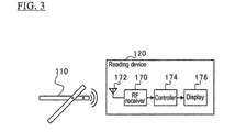
- FIG. 3 is a block diagram that illustrates the function of the reading device 120.
- the reading device 120 comprises an RF receiver 170, a reading antenna 172, a controller 174 and a display 176.
- the RF receiver 170 establishes wireless communication, all at once, with the plurality of RFID tags 156 that are fixed to the plurality of blades 150, by way of the reading antenna 172, by electromagnetic induction at 130 kHz to 135 kHz, 13.56 MHz or the like, or by radio waves of 433 MHz, 900 MHz, 2.45 GHz or the like. Establishment of wireless communication is described in detail further on.
- the controller 174 controls the entirety of the reading device 120 by way of semiconductor integrated circuits that include, for instance, a central processing unit (CPU), a ROM that stores programs and the like, and a RAM that serves as a work area.
- the controller 174 summates the thicknesses of the blades 150, as indicated by the read thickness information, to derive thereby the separation distance of the objects 130.
- Such a configuration allows performing, easily and accurately, the summation calculation, which is cumbersome for numerical values that include the number of digits that is difficult to grasp, e.g., values including decimal points. Human error can be avoided thereby.
- the type and thickness of the selected blades 150, and the total value thereof (separation distance) are all digitized. Accordingly, the information can be stored in a storage medium along with the date and time, and can be forwarded to the exterior via some other communication scheme. This enables, for instance, statistical processing and the like relating to the objects and the time and date.
- the display 176 which is made up of a liquid crystal display, an organic electro luminescent (EL) display or the like, displays the separation distance as derived by the controller 174.
- EL organic electro luminescent
- RFIDs enable omni-directional wireless communication in the order of several cm to several m. In the present embodiment, however, the thickness of the selected blades 150 alone is to be grasped from among the prepared blades 150. Therefore, wireless communication is to be established with only the RFID tags 156 that are formed in the selected blades 150 and that are within a predetermined range 180 denoted by the dashed line in FIG. 2(b) .
- the reading antenna 172 of the reading device 120 is configured to have directionality so as to enable wireless communication with only those RFID tags 156 that are present within the predetermined range 180; alternatively, the intensity of the radio waves is adjusted and the communication range of the reading antenna 172 is limited to the predetermined range 180.
- the relationship between the first ends 150a of the blades 150 and the RFID tags 156 is set up as described below, in such a manner that, during measurement, the RFID tags 156 that are fixed to the second ends 150c of the blades 150 are present within the predetermined range 180, in a state where the first ends 150a of the blades 150 are pinched between objects.
- the central angles, centered on the pivot pin 154, that are formed by wire connections to the first ends 150a of the blade 150 extending from the pivot pin 154 and the wire connections to the RFID tags 156 extending from the pivot pin 154, are set to be equal, and likewise, and the distances between the pivot pin 154 and the RFID tags 156 are likewise set to be equal, across the blades 150.
- the central angles formed by the wire connections from the pivot pin 154 to the first ends 150a of the blades 150 and the wire connections from the pivot pin 154 to the RFID tags 156 are all 180° angles, and the distances from the pivot pin 154 to the RFID tags 156 in the blades 150 are likewise equal.
- the RFID tags 156 of the respective superposed blades 150 become likewise superposed in the thickness direction. Therefore, all the RFID tags 156 of the selected blades 150 can be kept within the predetermined range 180 with respect to the reading antenna 172 of the reading device 120.
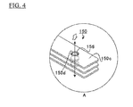
- FIG. 4 is an enlarged diagram of portion A in FIG. 2(b) .
- the surroundings of the RFID tags 156 are configured as described below in such a way so as to enable wireless communication, with good efficiency, between the reading antenna 172 and the RFID tags 156 superposed as described above.
- the blades 150 are formed of a conductor, such as a metal or the like and the RFID tags 156 are fixed at a position at which the conductor is absent in at least one direction.
- the blades 150 are formed of a metal, which is a conductor; also, the through-holes 150d are formed in the direction at which the RFID tags 156 overlap (thickness direction of the blades 150), as indicated by the arrow in FIG. 4 . Therefore, the overlapping RFID tags 156 form a passageway for radio waves only in the thickness direction of the blade 150, while being surrounded by conductors in the length direction and the width direction of the blades 150.
- the reading device 120 can establish wireless communication reliably in the direction denoted by the white arrow in FIG. 4 . If the RFID tags 156 have directionality, that direction may overlap the direction (thickness direction of the blades 150) at which the conductors are absent.
- the reading antenna 172 can establish reliably wireless communication only with the plurality of targeted RFID tags 156, and a shield can be formed between the plurality of targeted RFID tags 156 and other RFID tags 156 that are fixed to non-selected blades 150. Therefore, no erroneous wireless communication is established, and, accordingly, there can be efficiently aggregated the thickness information of the target RFID tags 156 alone, and the separation distance can be worked out accurately.
- the passive-type RFID tags 156 transmit the thickness information to the reading device 120 through superposition (reflection) of a modulated signal of the thickness information onto the portion of the unmodulated carrier of radio waves from the reading device 120. Upon measurement, therefore, the plurality of RFID tags 156 reacts all at once with the radio waves of the reading device 120.
- thickness information can be acquired all at once by relying on various techniques, for instance setting communication frequencies dissimilar from those of the RFID tags 156, and establishing time-division wireless communication, by varying the communication frequency, or by setting dissimilar timings at which the modulated signal is superposed on the portion of the unmodulated carrier of the radio waves from the reading device 120.
- FIG. 5 is a flowchart illustrating the flow of a separation distance determination method that utilizes the thickness gauge 110 and the reading device 120.
- the measurer selects one or a plurality of blades 150, from the thickness gauge 110, in accordance with the separation distance of the objects 130, and inserts the plurality of blades 150 between the objects 130.
- the measurer brings the reading device 120 close to the second ends 150c of the inserted blades 150 in such a manner that the reading antenna 172 becomes positioned in the thickness direction of the blades 150.
- the reading device 120 transmits radio waves that comprise information for reading the thickness information (step S200), and determines whether or not there is a response from the RFID tags 156 (step S202). The reading device 120 repeats this response determination until there is a response from the RFID tags 156 (NO in step S202). When there is a response (YES in step S202), the reading device 120 reads the thickness information by way of the RF receiver 170 (step S204).
- the controller 174 Upon reading of the thickness information, the controller 174 summates the thicknesses of each of the blades 150 as denoted by the read thickness information, to derive thereby the separation distance of the objects 130 (step S206).
- the display 176 displays the separation distance derived by the controller 174 (step S208).
- the separation distance determination system 100 and the separation distance determination method explained above make it possible to obtain, easily and accurately, a substantial separation distance of a gap between objects.
- the thickness information of the blades 150 can be acquired easily and reliably by way of the RFID tags 156, while human error can be avoided through automatic calculation by the reading device 120. Measurement of the separation distance can be rendered thus more convenient, while affording greater work efficiency.
- the direction in which conductors are absent is the thickness direction of the blades 150, but, as illustrated in Fig 6 , a cutout may be provided instead in the second ends 150c of the blades 150, in the length direction of the latter, such that the RFID tags 156 are fixed in that cutout.
- the reading antenna 172 establishes wireless communication in the length direction of the blades 150, as indicated by the white arrow in FIG. 6 .
- the thickness direction of the blades 150 can be covered by conductors, and contact between the measurer and the RFID tags 156 can be avoided.
- the plurality of blades 150 is accommodated in the folder 152, but the folder 152 need not be provided; also, the plurality of blades 150 may be connected to the pivot pin 154, or the blades 150 may be used independently from each other.
- Processing in the various steps in the separation distance determination method of the present description need not necessarily be carried out in a time series according to sequence set forth in the flowchart, and may be carried out in parallel or in subroutines.
- the present invention can be used in a separation distance determination system for determination of a separation distance between objects, and in a thickness gauge that is inserted between objects.
Landscapes
- Physics & Mathematics (AREA)
- General Physics & Mathematics (AREA)
- A Measuring Device Byusing Mechanical Method (AREA)
- Measurement Of Length, Angles, Or The Like Using Electric Or Magnetic Means (AREA)
- Length-Measuring Instruments Using Mechanical Means (AREA)
Abstract
Description
- The present invention relates to a separation distance determination system for determination of a separation distance between objects, and to a thickness gauge that is adapted to be inserted between the objects.
- In some instances, the separation distance of gaps that arise, or that are intentionally provided, between objects in structures and machinery and equipment, is measured, with high precision and at a high resolution of 0.01 mm. However, in some instances it is not possible to simply use a distance-measuring tool such as a caliper or the like if the separation distance of a gap to be measured is narrow.
- In capacitive GAP measuring instruments, for instance, separation distances can be obtained by inserting a thin sheet-like probe into a gap between objects, causing current to flow between the objects and an electrode (probe), and measuring the voltage at that time.
- However, accurate separation distances have been difficult to obtain using such measuring instruments in cases where, for instance, the thickness of the probe and the position of the probe between objects, among other parameters, are subjected to numerous limitations, or instances where objects are not conductors, for instance in the case of carbon-fiber reinforced plastic (CFRP).
- A technology has been disclosed (for instance, in Japanese Unexamined Patent Application Publication
JP-A-8-304 061 - This technology does not depend on the material of the objects; however, the technology allows only measuring the separation distance of the opening (inlet) of the gap between the objects. The measurement result was in some instances different from the substantial separation distance between opposing planes in the gap.
- Therefore, thickness gauges are used that allow obtaining the substantial separation distance of the gap between the objects, without limitation on the material of the objects, in cases where a separation distance is to be measured with high resolution and high precision (for instance, Japanese Unexamined Utility Model (Registration) Application Publication No.
S64-034 501 - In such a thickness gauge, the separation distance can be obtained by inserting a plurality of plate-like blades, of known thickness, between objects, and by summating then the thicknesses of the plurality of inserted blades. Another known technology for preventing human error involves measuring the separation distance all at once, using a caliper, with the blades inserted in the gap, instead of through summation of the thicknesses of the plurality of blades.
- In the above-described technology that utilizes concomitantly a thickness gauge and a caliper, a number of blades in a plurality of bundled blades, as the thickness gauge, are selectively inserted between the objects, and hence alternate blades are selected, i.e. first blade, fifth blade and ninth blade, depending on the separation distance between the objects.
- Therefore, when the caliper was applied, with the blades inserted in the gap, a concern arose in that the caliper might derive a separation distance that was greater than the actual separation distance in proportion to a gap that may arise between the inserted blades at sites other than the insertion portion.
- In the light of the above, it is an object of the present invention to provide a separation distance determination system, and a thickness gauge, that make it possible to obtain, easily and accurately, a substantial separation distance of a gap between objects, while avoiding human error.
- An aspect of the present invention provides a separation distance determination system that derives a separation distance between objects by using a thickness gauge that is inserted between the objects and a reading device.
- The thickness gauge includes: a plurality of blades having first ends adapted to be inserted between the objects; and RFID tags respectively fixed to part of the blades, with these RFID tags being adapted to readably store thickness information corresponding to the thickness of the respective blades, and the reading device includes: an RF receiver adapted for establishing contact-less communication with the RFID tags and for reading the thickness information; and a controller adapted for summating the thicknesses of the blades, as denoted by the read thickness information, to derive thereby the separation distance.
- Another aspect of the present invention provides a thickness gauge that has a plurality of blades having first ends adapted to be inserted between the objects; and RFID tags respectively fixed to part of the blades. These RFID tags are adapted to readably store thickness information corresponding to the thicknesses of the respective blades.
- Through-holes may be provided respectively in the plurality of blades, the thickness gauge may further have a pivot pin inserted through the through-holes of the plurality of blades, with the plurality of blades being able to pivot about the pivot pin.
- The plurality of blades may be configured in which central angles, centered on the pivot pin and formed by a connection extending from the pivot pin to the first end of each of the blades and by a connection extending from the pivot pin to the RFID tags, may be identical to one another and in which distances between the pivot pin and the RFID tags may be identical to one another.
- The blades may be formed of a conductor, and the RFID tags may be fixed at a position at which the conductor is absent in at least one direction.
- The present invention makes it possible to obtain, easily and accurately, a substantial separation distance of a gap between objects, and to enhance convenience and work efficiency, while avoiding human error.
-
- FIG. 1
- is an explanatory diagram for explaining schematically the function of a separation distance determination system;
- FIG. 2
- is a set of external-view diagrams including
FIG. 2(a) and FIG. 2(b) for illustrating the configuration of a thickness gauge; - FIG. 3
- is a block diagram that illustrates the function of a reading device;
- FIG. 4
- is an enlarged diagram of portion A in
FIG. 2(b) ; - FIG. 5
- is a flowchart illustrating the flow of a separation distance determination method that utilizes a thickness gauge and a reading device; and
- FIG. 6
- is an explanatory diagram for explaining another structure of the blades.
- Preferred embodiments of the present invention are explained in detail below with reference to accompanying drawings. The dimensions, materials and other specific numerical values set forth in the embodiments are given merely by way of illustration in order to make the invention easier to comprehend, and, unless explicitly stated, are not meant to limit the present invention in any way.
- In the present description and the drawings, elements that have substantially the same function and configuration are denoted by the same reference numerals, and a recurrent explanation thereof will be omitted. Elements that are not directly related to the present invention are not depicted in the drawings.
-
FIG. 1 is an explanatory diagram for explaining the schematic function of a separationdistance determination system 100. AsFIG. 1 shows, the separation distance determination system 140 is made up of athickness gauge 110 and areading device 120. The present embodiment aims at measuring, with high resolution and high precision, the separation distance of the gaps that arise, or are intentionally provided between objects, in structures (buildings) and machinery and equipment (aircraft, automobiles, marine vessels). - Conceivable examples of object gaps, include, for instance, gaps in pistons, cylinders and exteriors (for instance, carbon-fiber reinforced plastic), as well as gaps between iron cores and coils in generators, electric motors and the like. The separation
distance determination system 100 measures mainly gaps between opposing planes in the object. - The
thickness gauge 110 is a tool such that a part thereof (blade) is inserted between objects to measure, with high resolution and high precision, the substantial separation distance between the objects. Thereading device 120 establishes wireless communication with thethickness gauge 110, and derives automatically the separation distance on the basis of which blades, and how many, are inserted. Thethickness gauge 110 and thereading device 120 are explained in detail further on. -
FIG. 2 is a set of external-view diagrams for illustrating the configuration of thethickness gauge 110. In particular,FIG. 2(a) illustrates a housed configuration andFIG. 2(b) illustrates a configuration during measurement. Thethickness gauge 110 is made up ofblades 150, afolder 152, apivot pin 154, and a radio frequency identification (RFID)tag 156. - For instance, the
blades 150 are each formed as a thin metal plate of thickness ranging from 0.01 mm to 1.00 mm, and are ordinarily prepared as a plurality thereof in onethickness gauge 110. A plurality of combinations of such metal plates allows for instance expressing thicknesses ranging from 0.01 mm to 1.00 mm with a resolution of 0.01 mm. The thickness of the metal plate need not necessarily be dissimilar for eachblade 150. The blades may have thus identical thickness. - The
blades 150 are formed of pliable thin metal plates of identical length. Therefore, asFIG. 2(b) shows, a plurality of blades 150 (hereafter also referred to as selected blades 150) that is selected out of the preparedblades 150 is bent in the thickness direction. First ends 150a ofrespective blades 150 can thus be superposed on each other. The measurer selects a combination ofblades 150 that correspond to the gap between theobjects 130, superposes thefirst ends 150a by swiveling only the selectedblades 150, as denoted by the arrow inFIG. 2(b) , and inserts the superposed blades 150 (selected blades 150) into the gap. The measurer modifies the combination ofblades 150 if the thickness of the superposedblades 150 and the gap do not match each other. - Through-
holes 150b for insertion of a below-describedpivot pin 154 are provided in theblades 150. The through-holes 150b are formed in such a manner that the positions thereof are identical across theblades 150. - For instance, through-holes having a diameter of 5 mm, or grooves (hereafter simply through-
holes 150d), for fixing the RFID tags 156, are provided in second ends 150c of theblades 150. The through-holes 150d may have any shape, for instance circular, rectangular or the like, so long as the RFID tags 156 can be fixed therein. - The
folder 152 is formed through bending of a metal plate to a C-shape, in such a manner that the ends of the metal plate oppose each other. As illustrated inFIG. 2(a) , thefolder 152 accommodates the prepared plurality ofblades 150. Thepivot pin 154 is formed as a long pin the length whereof corresponds to the thickness of thethickness gauge 110, such that thepivot pin 154 runs through the through-holes 150b of theblades 150, with theblades 150 accommodated in thefolder 152. Theblades 150 can pivot thus about the center of thepivot pin 154, as illustrated inFIG. 2(b) . - The RFID tags 156, which are wireless ICs having for instance a thickness of 0.8 mm or less (the thinner the RFID tags 156, the more preferable the latter are), are fixed in the through-
holes 150d that are formed in theblades 150. Thickness information corresponding to the thickness ofrespective blades 150 is stored, readably by contact-less wireless communication, in the RFID tags 156. - The thickness information may be information that directly denotes the thickness, for instance 0.01 mm or 0.10 mm, or may be information that denotes indirectly the thickness, for instance an identifier or the like of the
respective blade 150, so long as a correspondence relationship therebetween is defined in the below-describedreading device 120. Herein, the term contact-less indicates that wireless communication can be established both in a contact state and in a noncontact state. - The RFID tags 156 include active-type and passive-type tags. Passive-type tags that take up a small volume are used in the present case, but active-type tags are not ruled out. Passive-type RFID tags 156 have ordinarily no built-in batteries, and operate using an energy source in the form of radio waves that are received from the below-described
reading device 120. The thickness information is transmitted to thereading device 120 through superposition (reflection) of a modulated signal of the thickness information onto the portion of an unmodulated carrier of radio waves from thereading device 120. - The RFID tags 156 are fixed to the
blades 150 by, for instance, being adhered to a plastic film that is disposed on the rear side of the through-holes 150d that are formed in theblades 150, or by molding, using a resin or the like, with the RFID tags 156 embedded in the through-holes 150d. Preferably, the plastic film, resin or the like has low conductivity (is non-shielding) and elasticity. -
FIG. 3 is a block diagram that illustrates the function of thereading device 120. Thereading device 120 comprises anRF receiver 170, areading antenna 172, acontroller 174 and adisplay 176. - When the measurer brings the reading
antenna 172 close to the second ends 150c of theblades 150 of thethickness gauge 110, theRF receiver 170 establishes wireless communication, all at once, with the plurality ofRFID tags 156 that are fixed to the plurality ofblades 150, by way of thereading antenna 172, by electromagnetic induction at 130 kHz to 135 kHz, 13.56 MHz or the like, or by radio waves of 433 MHz, 900 MHz, 2.45 GHz or the like. Establishment of wireless communication is described in detail further on. - The
controller 174 controls the entirety of thereading device 120 by way of semiconductor integrated circuits that include, for instance, a central processing unit (CPU), a ROM that stores programs and the like, and a RAM that serves as a work area. By way of theRF receiver 170, thecontroller 174 summates the thicknesses of theblades 150, as indicated by the read thickness information, to derive thereby the separation distance of theobjects 130. Such a configuration allows performing, easily and accurately, the summation calculation, which is cumbersome for numerical values that include the number of digits that is difficult to grasp, e.g., values including decimal points. Human error can be avoided thereby. - The type and thickness of the selected
blades 150, and the total value thereof (separation distance) are all digitized. Accordingly, the information can be stored in a storage medium along with the date and time, and can be forwarded to the exterior via some other communication scheme. This enables, for instance, statistical processing and the like relating to the objects and the time and date. - The
display 176, which is made up of a liquid crystal display, an organic electro luminescent (EL) display or the like, displays the separation distance as derived by thecontroller 174. - The establishment of wireless communication is described in detail next. So-called RFIDs enable omni-directional wireless communication in the order of several cm to several m. In the present embodiment, however, the thickness of the selected
blades 150 alone is to be grasped from among theprepared blades 150. Therefore, wireless communication is to be established with only the RFID tags 156 that are formed in the selectedblades 150 and that are within apredetermined range 180 denoted by the dashed line inFIG. 2(b) . - Therefore, the reading
antenna 172 of thereading device 120 is configured to have directionality so as to enable wireless communication with only thoseRFID tags 156 that are present within thepredetermined range 180; alternatively, the intensity of the radio waves is adjusted and the communication range of thereading antenna 172 is limited to thepredetermined range 180. - The relationship between the first ends 150a of the
blades 150 and the RFID tags 156 is set up as described below, in such a manner that, during measurement, the RFID tags 156 that are fixed to the second ends 150c of theblades 150 are present within thepredetermined range 180, in a state where the first ends 150a of theblades 150 are pinched between objects. - Specifically, the central angles, centered on the
pivot pin 154, that are formed by wire connections to the first ends 150a of theblade 150 extending from thepivot pin 154 and the wire connections to the RFID tags 156 extending from thepivot pin 154, are set to be equal, and likewise, and the distances between thepivot pin 154 and the RFID tags 156 are likewise set to be equal, across theblades 150. - In the present embodiment, as illustrated in
FIG. 2(b) , the central angles formed by the wire connections from thepivot pin 154 to the first ends 150a of theblades 150 and the wire connections from thepivot pin 154 to the RFID tags 156 are all 180° angles, and the distances from thepivot pin 154 to the RFID tags 156 in theblades 150 are likewise equal. - As a result, when the plurality of
blades 150 that are inserted between the plurality of objects, from among the plurality ofblades 150, is superposed in the thickness direction, the RFID tags 156 of the respective superposedblades 150 become likewise superposed in the thickness direction. Therefore, all the RFID tags 156 of the selectedblades 150 can be kept within thepredetermined range 180 with respect to thereading antenna 172 of thereading device 120. -
FIG. 4 is an enlarged diagram of portion A inFIG. 2(b) . The surroundings of the RFID tags 156 are configured as described below in such a way so as to enable wireless communication, with good efficiency, between the readingantenna 172 and the RFID tags 156 superposed as described above. Specifically, theblades 150 are formed of a conductor, such as a metal or the like and the RFID tags 156 are fixed at a position at which the conductor is absent in at least one direction. - In the present embodiment, the
blades 150 are formed of a metal, which is a conductor; also, the through-holes 150d are formed in the direction at which the RFID tags 156 overlap (thickness direction of the blades 150), as indicated by the arrow inFIG. 4 . Therefore, the overlapping RFID tags 156 form a passageway for radio waves only in the thickness direction of theblade 150, while being surrounded by conductors in the length direction and the width direction of theblades 150. - Therefore, the
reading device 120 can establish wireless communication reliably in the direction denoted by the white arrow inFIG. 4 . If the RFID tags 156 have directionality, that direction may overlap the direction (thickness direction of the blades 150) at which the conductors are absent. - By virtue of such a configuration, the reading
antenna 172 can establish reliably wireless communication only with the plurality of targeted RFID tags 156, and a shield can be formed between the plurality of targetedRFID tags 156 andother RFID tags 156 that are fixed tonon-selected blades 150. Therefore, no erroneous wireless communication is established, and, accordingly, there can be efficiently aggregated the thickness information of thetarget RFID tags 156 alone, and the separation distance can be worked out accurately. - As described above, the passive-type RFID tags 156 transmit the thickness information to the
reading device 120 through superposition (reflection) of a modulated signal of the thickness information onto the portion of the unmodulated carrier of radio waves from thereading device 120. Upon measurement, therefore, the plurality of RFID tags 156 reacts all at once with the radio waves of thereading device 120. - In the separation
distance determination system 100, accordingly, thickness information can be acquired all at once by relying on various techniques, for instance setting communication frequencies dissimilar from those of the RFID tags 156, and establishing time-division wireless communication, by varying the communication frequency, or by setting dissimilar timings at which the modulated signal is superposed on the portion of the unmodulated carrier of the radio waves from thereading device 120. -
FIG. 5 is a flowchart illustrating the flow of a separation distance determination method that utilizes thethickness gauge 110 and thereading device 120. The measurer selects one or a plurality ofblades 150, from thethickness gauge 110, in accordance with the separation distance of theobjects 130, and inserts the plurality ofblades 150 between theobjects 130. - When the thickness of the overlapping
blades 150 matches the separation distance, the measurer brings thereading device 120 close to the second ends 150c of the insertedblades 150 in such a manner that the readingantenna 172 becomes positioned in the thickness direction of theblades 150. - By way of the
RF receiver 170, thereading device 120 transmits radio waves that comprise information for reading the thickness information (step S200), and determines whether or not there is a response from the RFID tags 156 (step S202). Thereading device 120 repeats this response determination until there is a response from the RFID tags 156 (NO in step S202). When there is a response (YES in step S202), thereading device 120 reads the thickness information by way of the RF receiver 170 (step S204). - Upon reading of the thickness information, the
controller 174 summates the thicknesses of each of theblades 150 as denoted by the read thickness information, to derive thereby the separation distance of the objects 130 (step S206). Thedisplay 176 displays the separation distance derived by the controller 174 (step S208). - Through the use of the
thickness gauge 110, the separationdistance determination system 100 and the separation distance determination method explained above make it possible to obtain, easily and accurately, a substantial separation distance of a gap between objects. - Also, the thickness information of the
blades 150 can be acquired easily and reliably by way of the RFID tags 156, while human error can be avoided through automatic calculation by thereading device 120. Measurement of the separation distance can be rendered thus more convenient, while affording greater work efficiency. - Preferred embodiments of the present invention have been explained above with reference to accompanying drawings, but the present invention is not meant in any way to be limited to these embodiments. It will be apparent to a person skilled in the art that various modifications and alterations can be conceivably made without departing from the scope of the present invention. It is understood that such modifications and alterations belong, as a matter of course, to the technical scope of the present invention.
- In the above-described embodiment, for instance, the direction in which conductors are absent is the thickness direction of the
blades 150, but, as illustrated inFig 6 , a cutout may be provided instead in the second ends 150c of theblades 150, in the length direction of the latter, such that the RFID tags 156 are fixed in that cutout. - In that case, the reading
antenna 172 establishes wireless communication in the length direction of theblades 150, as indicated by the white arrow inFIG. 6 . As a result, the thickness direction of theblades 150 can be covered by conductors, and contact between the measurer and the RFID tags 156 can be avoided. - In the above-described embodiment, an example has been explained in which the plurality of
blades 150 is accommodated in thefolder 152, but thefolder 152 need not be provided; also, the plurality ofblades 150 may be connected to thepivot pin 154, or theblades 150 may be used independently from each other. - Processing in the various steps in the separation distance determination method of the present description need not necessarily be carried out in a time series according to sequence set forth in the flowchart, and may be carried out in parallel or in subroutines.
- The present invention can be used in a separation distance determination system for determination of a separation distance between objects, and in a thickness gauge that is inserted between objects.
-
- 100
- = separation distance determination system
- 110
- = thickness gauge
- 120
- = reading device
- 150
- = blade
- 150a
- = first end
- 150b
- = through-hole
- 150c
- = second end
- 150d
- = through-hole
- 152
- = folder
- 154
- = pivot pin
- 156
- = RFID tag
- 170
- = RF receiver
- 172
- = reading antenna
- 174
- = controller
- 176
- = display
Claims (5)
- A thickness gauge (110), comprising:- a plurality of blades (150) having first ends (150a) adapted to be inserted between objects for detecting a separation distance; and- RFID tags (156) respectively fixed to part (150c) of the blades (150), the RFID tags (156) being adapted to readably store thickness information corresponding to the thicknesses of the respective blades (150).
- The thickness gauge (110) according to claim 1,
wherein through-holes (150b) are provided respectively in the plurality of blades (150),
wherein the thickness gauge (110) further comprises a pivot pin (154) inserted through the through-holes (150b) of the plurality of blades (150), and
wherein with the plurality of blades (150) is able to pivot about the pivot pin (154). - The thickness gauge (110) according to claim 2,
wherein the plurality of blades (150) are configured in which central angles, centered on the pivot pin (154) and formed by a connection extending from the pivot pin (154) to the first end (150c) of each of the blades (150) and by a connection extending from the pivot pin (154) to the RFID tags (156), are identical to one another and in which distances between the pivot pin (154) and the RFID tags (156) are identical to one another. - The thickness gauge (110) according to any of claims 1 to 3, wherein the blades (150) are formed respectively of a conductor, and wherein the RFID tags (156) are fixed at positions (150c) at which the respective conductor is absent in at least one direction.
- A separation distance determination system (100) for determining a separation distance between objects by using a thickness gauge (110), which is adapted to be inserted between the objects, and a reading device (120),
wherein the system comprises a thickness gauge (110) according to any one of the claims 1 to 4; and
wherein the reading device (120) comprises:- an RF receiver (170) adapted for establishing contact-less communication with the RFID tags (156) and for reading the thickness information; and- a controller (174) adapted for summating the thicknesses of the blades (150), as denoted by the read thickness information, to determine thereby the separation distance.
Applications Claiming Priority (1)
| Application Number | Priority Date | Filing Date | Title |
|---|---|---|---|
| JP2012012582A JP5443522B2 (en) | 2012-01-25 | 2012-01-25 | Separation distance derivation system and thickness gauge |
Publications (2)
| Publication Number | Publication Date |
|---|---|
| EP2620740A1 true EP2620740A1 (en) | 2013-07-31 |
| EP2620740B1 EP2620740B1 (en) | 2015-05-13 |
Family
ID=47603389
Family Applications (1)
| Application Number | Title | Priority Date | Filing Date |
|---|---|---|---|
| EP20130152004 Not-in-force EP2620740B1 (en) | 2012-01-25 | 2013-01-21 | Separation distance determination system and thickness gauge |
Country Status (4)
| Country | Link |
|---|---|
| US (1) | US8832951B2 (en) |
| EP (1) | EP2620740B1 (en) |
| JP (1) | JP5443522B2 (en) |
| CN (1) | CN103267457B (en) |
Cited By (3)
| Publication number | Priority date | Publication date | Assignee | Title |
|---|---|---|---|---|
| WO2014062484A1 (en) * | 2012-10-19 | 2014-04-24 | General Electric Company | Digital feeler gauge and method of using same |
| WO2017030667A1 (en) * | 2015-08-18 | 2017-02-23 | General Electric Company | Secondary data communication methodology for metrological device augmentation |
| EP3336483A1 (en) * | 2016-12-15 | 2018-06-20 | General Electric Company | Digital wireless feeler gauge |
Families Citing this family (13)
| Publication number | Priority date | Publication date | Assignee | Title |
|---|---|---|---|---|
| US9441937B2 (en) | 2012-10-19 | 2016-09-13 | General Electric Company | Method and apparatus for measuring thickness of an object |
| US20160084626A1 (en) * | 2014-09-22 | 2016-03-24 | Lisle Corporation | Brake pad measuring gauge |
| US9500462B2 (en) | 2013-02-14 | 2016-11-22 | Lisle Corporation | Brake lining gauge measurement tools |
| US9389071B2 (en) * | 2013-10-24 | 2016-07-12 | Bell Helicopter Textron Inc. | Estimating thickness of a material layer on an aircraft |
| CN105258609B (en) * | 2015-11-11 | 2018-12-14 | 中车长江车辆有限公司 | For quickly detecting the Special caliper and application method in object gap |
| US10240909B2 (en) | 2016-10-17 | 2019-03-26 | The Boeing Company | Three-dimensional gap measurement systems and methods |
| US10352684B2 (en) * | 2016-10-17 | 2019-07-16 | The Boeing Company | Three-dimensional gap measurement systems and methods |
| EP3620745B1 (en) * | 2018-09-06 | 2021-06-02 | TESA Sàrl | Portable measuring device with autoconfiguration |
| CN110296644B (en) * | 2019-06-24 | 2021-08-31 | 中国航发动力股份有限公司 | A tool and method for measuring the variation of blade throwing and trimming |
| US10935360B1 (en) * | 2019-12-30 | 2021-03-02 | James Mah | Methods and devices for establishing gap dimensions |
| US11561078B2 (en) * | 2020-04-03 | 2023-01-24 | The Boeing Company | Methods and systems for measuring gaps between exterior structures and interior structures |
| CN111968476B (en) * | 2020-08-11 | 2022-04-01 | 广东电网有限责任公司 | Line-tree dynamic distance simulation device and line-tree dynamic distance simulation method |
| US11674788B2 (en) * | 2020-12-08 | 2023-06-13 | Monte Lutz | Valve clearance measuring method and assembly |
Citations (3)
| Publication number | Priority date | Publication date | Assignee | Title |
|---|---|---|---|---|
| US987703A (en) * | 1908-11-27 | 1911-03-28 | Peter A Curtin | Combination measuring-tool. |
| US2217648A (en) * | 1940-03-15 | 1940-10-08 | Starrett L S Co | Adjustable locking multileaf gauge |
| GB994713A (en) * | 1962-06-08 | 1965-06-10 | Standard Telephones Cables Ltd | A mechanical arrangement for defining a relatively small distance |
Family Cites Families (21)
| Publication number | Priority date | Publication date | Assignee | Title |
|---|---|---|---|---|
| JPS6434501U (en) * | 1987-08-26 | 1989-03-02 | ||
| US5063687A (en) * | 1990-09-27 | 1991-11-12 | Equipment Development Services | Adjustable measuring parallels |
| US5471757A (en) * | 1994-05-02 | 1995-12-05 | Mcdonald; Randolph C. | Oil filter size determination kit |
| US5665973A (en) * | 1995-10-25 | 1997-09-09 | Lockheed Corporation | Penetrant transparent comparator |
| US5551162A (en) * | 1994-10-12 | 1996-09-03 | Js Research And Development, Inc. | Hand-held gap and contour measuring gauge |
| AU4194796A (en) * | 1994-10-12 | 1996-05-06 | Js Research And Development, Inc. | Hand-held gap and contour measuring gauge |
| JPH08304061A (en) * | 1995-05-02 | 1996-11-22 | Mitsubishi Heavy Ind Ltd | Clearance gauge |
| JPH10170205A (en) * | 1996-12-12 | 1998-06-26 | Fuji Photo Film Co Ltd | Gap dimension detecting method and its detecting laminated body |
| US6279241B1 (en) * | 1999-03-03 | 2001-08-28 | Industrial Technology Research Institute | Thickness gauge |
| US6438859B1 (en) * | 2001-01-22 | 2002-08-27 | Honeywell International Inc. | Calibrated arcuate wedge tool for measuring a gap adjacent to a curved surface |
| US6813842B2 (en) * | 2003-04-14 | 2004-11-09 | Sun Yieh Industrial Co., Ltd. | Filler gauge with flexible measurement |
| JP4509588B2 (en) * | 2004-01-30 | 2010-07-21 | 株式会社ミツトヨ | Step / gap measuring device |
| JP2005315288A (en) * | 2004-04-27 | 2005-11-10 | Jatco Ltd | Inspection device for continuously variable transmission belts |
| US7134219B2 (en) * | 2004-05-21 | 2006-11-14 | The Regents Of The University Of California | Fiber optic gap gauge |
| JP2006026827A (en) * | 2004-07-16 | 2006-02-02 | Aoi Electronics Co Ltd | Nano gripper device with measuring function |
| JP2007256008A (en) * | 2006-03-22 | 2007-10-04 | Mitsubishi Materials Corp | RFID system for measuring bolt strain with bolt with tag and clamping tool with reader |
| KR100844737B1 (en) * | 2006-11-21 | 2008-07-07 | 기아자동차주식회사 | Seal gap measuring device of automobile |
| JP2008286674A (en) * | 2007-05-18 | 2008-11-27 | Central Motor Co Ltd | Clearance gauge for product |
| JP2009257798A (en) * | 2008-04-14 | 2009-11-05 | Nihon Meccs Co Ltd | Gap measuring gauge |
| CN201242420Y (en) * | 2008-08-01 | 2009-05-20 | 比亚迪股份有限公司 | Surface difference clearance ruler |
| JP2011227811A (en) * | 2010-04-22 | 2011-11-10 | Hitachi-Ge Nuclear Energy Ltd | Work management system and work management method |
-
2012
- 2012-01-25 JP JP2012012582A patent/JP5443522B2/en not_active Expired - Fee Related
-
2013
- 2013-01-18 US US13/745,559 patent/US8832951B2/en active Active
- 2013-01-21 EP EP20130152004 patent/EP2620740B1/en not_active Not-in-force
- 2013-01-25 CN CN201310028800.XA patent/CN103267457B/en not_active Expired - Fee Related
Patent Citations (3)
| Publication number | Priority date | Publication date | Assignee | Title |
|---|---|---|---|---|
| US987703A (en) * | 1908-11-27 | 1911-03-28 | Peter A Curtin | Combination measuring-tool. |
| US2217648A (en) * | 1940-03-15 | 1940-10-08 | Starrett L S Co | Adjustable locking multileaf gauge |
| GB994713A (en) * | 1962-06-08 | 1965-06-10 | Standard Telephones Cables Ltd | A mechanical arrangement for defining a relatively small distance |
Cited By (5)
| Publication number | Priority date | Publication date | Assignee | Title |
|---|---|---|---|---|
| WO2014062484A1 (en) * | 2012-10-19 | 2014-04-24 | General Electric Company | Digital feeler gauge and method of using same |
| US8919004B2 (en) | 2012-10-19 | 2014-12-30 | General Electric Company | Digital feeler gauge and method of using same |
| WO2017030667A1 (en) * | 2015-08-18 | 2017-02-23 | General Electric Company | Secondary data communication methodology for metrological device augmentation |
| EP3336483A1 (en) * | 2016-12-15 | 2018-06-20 | General Electric Company | Digital wireless feeler gauge |
| US10393492B2 (en) | 2016-12-15 | 2019-08-27 | General Electric Company | Digital wireless feeler gauge |
Also Published As
| Publication number | Publication date |
|---|---|
| US20130185950A1 (en) | 2013-07-25 |
| CN103267457B (en) | 2015-05-06 |
| JP5443522B2 (en) | 2014-03-19 |
| EP2620740B1 (en) | 2015-05-13 |
| CN103267457A (en) | 2013-08-28 |
| JP2013152124A (en) | 2013-08-08 |
| US8832951B2 (en) | 2014-09-16 |
Similar Documents
| Publication | Publication Date | Title |
|---|---|---|
| EP2620740B1 (en) | Separation distance determination system and thickness gauge | |
| US8513915B2 (en) | Vehicle alignment for inductive charging | |
| CN103267911B (en) | The non-contact testing system and method for RFID label antenna | |
| EP1873548A1 (en) | Position determination system and position determination method | |
| CN109682292B (en) | Offset detection method and device and wireless charging system | |
| CA2789322A1 (en) | A system and method for measuring phase attributes of electrical grid system and equipment using a smart phone | |
| CN110412339B (en) | Current measuring device and method for power system | |
| CN105277793A (en) | Cable conductor alternating current resistance measuring method and system | |
| CN103344818A (en) | Non-contact electroscope and electroscopy | |
| CN110723019A (en) | Wireless charging guiding and positioning system and method and vehicle-mounted equipment | |
| CN104391269B (en) | Spatial orientation method and apparatus based on radio frequency identification technology | |
| CN110435468B (en) | Wireless charging positioning calibration method and system | |
| CN107846698A (en) | A kind of standing wave ratio measurement method and device | |
| EP3432021B1 (en) | Position detection system | |
| CN114252357A (en) | Metal surface crack monitoring based on RFID antenna sensor | |
| JP2016054596A (en) | Foreign matter detection device | |
| KR20190059156A (en) | Senser for measuring stress and system comprising the same | |
| ITMI20111017A1 (en) | METHOD OF LOCALIZATION OF AN EMITTER ELEMENT OF AN ELECTROMAGNETIC SIGNAL | |
| CN113359065A (en) | Antenna testing method, device and computer readable storage medium | |
| Omar et al. | Embedded active RFID with WSN for machine condition monitoring | |
| CN210803593U (en) | Wireless passive field strength probe | |
| CN208621004U (en) | A kind of powder coating calibrator | |
| CN214703792U (en) | Detection device for flexible radio frequency antenna | |
| CN104459279A (en) | Method for measuring wire current and electronic device | |
| CN113009241B (en) | Detection device and detection method for flexible radio frequency antenna |
Legal Events
| Date | Code | Title | Description |
|---|---|---|---|
| PUAI | Public reference made under article 153(3) epc to a published international application that has entered the european phase |
Free format text: ORIGINAL CODE: 0009012 |
|
| AK | Designated contracting states |
Kind code of ref document: A1 Designated state(s): AL AT BE BG CH CY CZ DE DK EE ES FI FR GB GR HR HU IE IS IT LI LT LU LV MC MK MT NL NO PL PT RO RS SE SI SK SM TR |
|
| AX | Request for extension of the european patent |
Extension state: BA ME |
|
| 17P | Request for examination filed |
Effective date: 20130724 |
|
| RBV | Designated contracting states (corrected) |
Designated state(s): AL AT BE BG CH CY CZ DE DK EE ES FI FR GB GR HR HU IE IS IT LI LT LU LV MC MK MT NL NO PL PT RO RS SE SI SK SM TR |
|
| RAP1 | Party data changed (applicant data changed or rights of an application transferred) |
Owner name: FUJI JUKOGYO KABUSHIKI KAISHA |
|
| GRAP | Despatch of communication of intention to grant a patent |
Free format text: ORIGINAL CODE: EPIDOSNIGR1 |
|
| RIC1 | Information provided on ipc code assigned before grant |
Ipc: G01B 7/14 20060101ALI20141110BHEP Ipc: G01B 5/14 20060101ALI20141110BHEP Ipc: G01V 15/00 20060101ALI20141110BHEP Ipc: G01B 7/06 20060101ALI20141110BHEP Ipc: G01B 3/30 20060101AFI20141110BHEP Ipc: G01B 3/50 20060101ALI20141110BHEP |
|
| INTG | Intention to grant announced |
Effective date: 20141124 |
|
| GRAS | Grant fee paid |
Free format text: ORIGINAL CODE: EPIDOSNIGR3 |
|
| GRAA | (expected) grant |
Free format text: ORIGINAL CODE: 0009210 |
|
| AK | Designated contracting states |
Kind code of ref document: B1 Designated state(s): AL AT BE BG CH CY CZ DE DK EE ES FI FR GB GR HR HU IE IS IT LI LT LU LV MC MK MT NL NO PL PT RO RS SE SI SK SM TR |
|
| REG | Reference to a national code |
Ref country code: GB Ref legal event code: FG4D |
|
| REG | Reference to a national code |
Ref country code: CH Ref legal event code: EP |
|
| REG | Reference to a national code |
Ref country code: IE Ref legal event code: FG4D |
|
| REG | Reference to a national code |
Ref country code: AT Ref legal event code: REF Ref document number: 727006 Country of ref document: AT Kind code of ref document: T Effective date: 20150615 |
|
| REG | Reference to a national code |
Ref country code: DE Ref legal event code: R096 Ref document number: 602013001713 Country of ref document: DE Effective date: 20150625 |
|
| REG | Reference to a national code |
Ref country code: AT Ref legal event code: MK05 Ref document number: 727006 Country of ref document: AT Kind code of ref document: T Effective date: 20150513 |
|
| REG | Reference to a national code |
Ref country code: NL Ref legal event code: MP Effective date: 20150513 |
|
| REG | Reference to a national code |
Ref country code: LT Ref legal event code: MG4D |
|
| PG25 | Lapsed in a contracting state [announced via postgrant information from national office to epo] |
Ref country code: ES Free format text: LAPSE BECAUSE OF FAILURE TO SUBMIT A TRANSLATION OF THE DESCRIPTION OR TO PAY THE FEE WITHIN THE PRESCRIBED TIME-LIMIT Effective date: 20150513 Ref country code: FI Free format text: LAPSE BECAUSE OF FAILURE TO SUBMIT A TRANSLATION OF THE DESCRIPTION OR TO PAY THE FEE WITHIN THE PRESCRIBED TIME-LIMIT Effective date: 20150513 Ref country code: LT Free format text: LAPSE BECAUSE OF FAILURE TO SUBMIT A TRANSLATION OF THE DESCRIPTION OR TO PAY THE FEE WITHIN THE PRESCRIBED TIME-LIMIT Effective date: 20150513 Ref country code: HR Free format text: LAPSE BECAUSE OF FAILURE TO SUBMIT A TRANSLATION OF THE DESCRIPTION OR TO PAY THE FEE WITHIN THE PRESCRIBED TIME-LIMIT Effective date: 20150513 Ref country code: NO Free format text: LAPSE BECAUSE OF FAILURE TO SUBMIT A TRANSLATION OF THE DESCRIPTION OR TO PAY THE FEE WITHIN THE PRESCRIBED TIME-LIMIT Effective date: 20150813 Ref country code: PT Free format text: LAPSE BECAUSE OF FAILURE TO SUBMIT A TRANSLATION OF THE DESCRIPTION OR TO PAY THE FEE WITHIN THE PRESCRIBED TIME-LIMIT Effective date: 20150914 |
|
| PG25 | Lapsed in a contracting state [announced via postgrant information from national office to epo] |
Ref country code: BG Free format text: LAPSE BECAUSE OF FAILURE TO SUBMIT A TRANSLATION OF THE DESCRIPTION OR TO PAY THE FEE WITHIN THE PRESCRIBED TIME-LIMIT Effective date: 20150813 Ref country code: IS Free format text: LAPSE BECAUSE OF FAILURE TO SUBMIT A TRANSLATION OF THE DESCRIPTION OR TO PAY THE FEE WITHIN THE PRESCRIBED TIME-LIMIT Effective date: 20150913 Ref country code: GR Free format text: LAPSE BECAUSE OF FAILURE TO SUBMIT A TRANSLATION OF THE DESCRIPTION OR TO PAY THE FEE WITHIN THE PRESCRIBED TIME-LIMIT Effective date: 20150814 Ref country code: RS Free format text: LAPSE BECAUSE OF FAILURE TO SUBMIT A TRANSLATION OF THE DESCRIPTION OR TO PAY THE FEE WITHIN THE PRESCRIBED TIME-LIMIT Effective date: 20150513 Ref country code: AT Free format text: LAPSE BECAUSE OF FAILURE TO SUBMIT A TRANSLATION OF THE DESCRIPTION OR TO PAY THE FEE WITHIN THE PRESCRIBED TIME-LIMIT Effective date: 20150513 Ref country code: LV Free format text: LAPSE BECAUSE OF FAILURE TO SUBMIT A TRANSLATION OF THE DESCRIPTION OR TO PAY THE FEE WITHIN THE PRESCRIBED TIME-LIMIT Effective date: 20150513 |
|
| PG25 | Lapsed in a contracting state [announced via postgrant information from national office to epo] |
Ref country code: DK Free format text: LAPSE BECAUSE OF FAILURE TO SUBMIT A TRANSLATION OF THE DESCRIPTION OR TO PAY THE FEE WITHIN THE PRESCRIBED TIME-LIMIT Effective date: 20150513 Ref country code: EE Free format text: LAPSE BECAUSE OF FAILURE TO SUBMIT A TRANSLATION OF THE DESCRIPTION OR TO PAY THE FEE WITHIN THE PRESCRIBED TIME-LIMIT Effective date: 20150513 |
|
| REG | Reference to a national code |
Ref country code: FR Ref legal event code: PLFP Year of fee payment: 4 |
|
| REG | Reference to a national code |
Ref country code: DE Ref legal event code: R097 Ref document number: 602013001713 Country of ref document: DE |
|
| PG25 | Lapsed in a contracting state [announced via postgrant information from national office to epo] |
Ref country code: SK Free format text: LAPSE BECAUSE OF FAILURE TO SUBMIT A TRANSLATION OF THE DESCRIPTION OR TO PAY THE FEE WITHIN THE PRESCRIBED TIME-LIMIT Effective date: 20150513 Ref country code: PL Free format text: LAPSE BECAUSE OF FAILURE TO SUBMIT A TRANSLATION OF THE DESCRIPTION OR TO PAY THE FEE WITHIN THE PRESCRIBED TIME-LIMIT Effective date: 20150513 Ref country code: RO Free format text: LAPSE BECAUSE OF NON-PAYMENT OF DUE FEES Effective date: 20150513 Ref country code: CZ Free format text: LAPSE BECAUSE OF FAILURE TO SUBMIT A TRANSLATION OF THE DESCRIPTION OR TO PAY THE FEE WITHIN THE PRESCRIBED TIME-LIMIT Effective date: 20150513 |
|
| PLBE | No opposition filed within time limit |
Free format text: ORIGINAL CODE: 0009261 |
|
| STAA | Information on the status of an ep patent application or granted ep patent |
Free format text: STATUS: NO OPPOSITION FILED WITHIN TIME LIMIT |
|
| 26N | No opposition filed |
Effective date: 20160216 |
|
| PG25 | Lapsed in a contracting state [announced via postgrant information from national office to epo] |
Ref country code: IT Free format text: LAPSE BECAUSE OF FAILURE TO SUBMIT A TRANSLATION OF THE DESCRIPTION OR TO PAY THE FEE WITHIN THE PRESCRIBED TIME-LIMIT Effective date: 20150513 |
|
| PG25 | Lapsed in a contracting state [announced via postgrant information from national office to epo] |
Ref country code: BE Free format text: LAPSE BECAUSE OF NON-PAYMENT OF DUE FEES Effective date: 20160131 Ref country code: SI Free format text: LAPSE BECAUSE OF FAILURE TO SUBMIT A TRANSLATION OF THE DESCRIPTION OR TO PAY THE FEE WITHIN THE PRESCRIBED TIME-LIMIT Effective date: 20150513 |
|
| PG25 | Lapsed in a contracting state [announced via postgrant information from national office to epo] |
Ref country code: BE Free format text: LAPSE BECAUSE OF FAILURE TO SUBMIT A TRANSLATION OF THE DESCRIPTION OR TO PAY THE FEE WITHIN THE PRESCRIBED TIME-LIMIT Effective date: 20150513 Ref country code: LU Free format text: LAPSE BECAUSE OF FAILURE TO SUBMIT A TRANSLATION OF THE DESCRIPTION OR TO PAY THE FEE WITHIN THE PRESCRIBED TIME-LIMIT Effective date: 20160121 |
|
| REG | Reference to a national code |
Ref country code: CH Ref legal event code: PL |
|
| PG25 | Lapsed in a contracting state [announced via postgrant information from national office to epo] |
Ref country code: MC Free format text: LAPSE BECAUSE OF FAILURE TO SUBMIT A TRANSLATION OF THE DESCRIPTION OR TO PAY THE FEE WITHIN THE PRESCRIBED TIME-LIMIT Effective date: 20150513 |
|
| PG25 | Lapsed in a contracting state [announced via postgrant information from national office to epo] |
Ref country code: CH Free format text: LAPSE BECAUSE OF NON-PAYMENT OF DUE FEES Effective date: 20160131 Ref country code: LI Free format text: LAPSE BECAUSE OF NON-PAYMENT OF DUE FEES Effective date: 20160131 |
|
| REG | Reference to a national code |
Ref country code: IE Ref legal event code: MM4A |
|
| REG | Reference to a national code |
Ref country code: FR Ref legal event code: PLFP Year of fee payment: 5 |
|
| PG25 | Lapsed in a contracting state [announced via postgrant information from national office to epo] |
Ref country code: IE Free format text: LAPSE BECAUSE OF NON-PAYMENT OF DUE FEES Effective date: 20160121 |
|
| REG | Reference to a national code |
Ref country code: DE Ref legal event code: R082 Ref document number: 602013001713 Country of ref document: DE Representative=s name: MEISSNER BOLTE PATENTANWAELTE RECHTSANWAELTE P, DE Ref country code: DE Ref legal event code: R081 Ref document number: 602013001713 Country of ref document: DE Owner name: SUBARU CORPORATION, JP Free format text: FORMER OWNER: FUJI JUKOGYO K.K., TOKIO/TOKYO, JP |
|
| PG25 | Lapsed in a contracting state [announced via postgrant information from national office to epo] |
Ref country code: SE Free format text: LAPSE BECAUSE OF FAILURE TO SUBMIT A TRANSLATION OF THE DESCRIPTION OR TO PAY THE FEE WITHIN THE PRESCRIBED TIME-LIMIT Effective date: 20150513 Ref country code: NL Free format text: LAPSE BECAUSE OF FAILURE TO SUBMIT A TRANSLATION OF THE DESCRIPTION OR TO PAY THE FEE WITHIN THE PRESCRIBED TIME-LIMIT Effective date: 20150513 |
|
| PG25 | Lapsed in a contracting state [announced via postgrant information from national office to epo] |
Ref country code: MT Free format text: LAPSE BECAUSE OF FAILURE TO SUBMIT A TRANSLATION OF THE DESCRIPTION OR TO PAY THE FEE WITHIN THE PRESCRIBED TIME-LIMIT Effective date: 20150513 |
|
| REG | Reference to a national code |
Ref country code: FR Ref legal event code: CD Owner name: SUBARU CORPORATION, JP Effective date: 20171114 |
|
| REG | Reference to a national code |
Ref country code: FR Ref legal event code: PLFP Year of fee payment: 6 |
|
| PG25 | Lapsed in a contracting state [announced via postgrant information from national office to epo] |
Ref country code: SM Free format text: LAPSE BECAUSE OF FAILURE TO SUBMIT A TRANSLATION OF THE DESCRIPTION OR TO PAY THE FEE WITHIN THE PRESCRIBED TIME-LIMIT Effective date: 20150513 Ref country code: HU Free format text: LAPSE BECAUSE OF FAILURE TO SUBMIT A TRANSLATION OF THE DESCRIPTION OR TO PAY THE FEE WITHIN THE PRESCRIBED TIME-LIMIT; INVALID AB INITIO Effective date: 20130121 Ref country code: CY Free format text: LAPSE BECAUSE OF FAILURE TO SUBMIT A TRANSLATION OF THE DESCRIPTION OR TO PAY THE FEE WITHIN THE PRESCRIBED TIME-LIMIT Effective date: 20150513 |
|
| PG25 | Lapsed in a contracting state [announced via postgrant information from national office to epo] |
Ref country code: MT Free format text: LAPSE BECAUSE OF FAILURE TO SUBMIT A TRANSLATION OF THE DESCRIPTION OR TO PAY THE FEE WITHIN THE PRESCRIBED TIME-LIMIT Effective date: 20160131 Ref country code: MK Free format text: LAPSE BECAUSE OF FAILURE TO SUBMIT A TRANSLATION OF THE DESCRIPTION OR TO PAY THE FEE WITHIN THE PRESCRIBED TIME-LIMIT Effective date: 20150513 Ref country code: TR Free format text: LAPSE BECAUSE OF FAILURE TO SUBMIT A TRANSLATION OF THE DESCRIPTION OR TO PAY THE FEE WITHIN THE PRESCRIBED TIME-LIMIT Effective date: 20150513 |
|
| PG25 | Lapsed in a contracting state [announced via postgrant information from national office to epo] |
Ref country code: AL Free format text: LAPSE BECAUSE OF FAILURE TO SUBMIT A TRANSLATION OF THE DESCRIPTION OR TO PAY THE FEE WITHIN THE PRESCRIBED TIME-LIMIT Effective date: 20150513 |
|
| PGFP | Annual fee paid to national office [announced via postgrant information from national office to epo] |
Ref country code: FR Payment date: 20230124 Year of fee payment: 11 |
|
| PGFP | Annual fee paid to national office [announced via postgrant information from national office to epo] |
Ref country code: GB Payment date: 20230119 Year of fee payment: 11 Ref country code: DE Payment date: 20230123 Year of fee payment: 11 |
|
| REG | Reference to a national code |
Ref country code: DE Ref legal event code: R119 Ref document number: 602013001713 Country of ref document: DE |
|
| GBPC | Gb: european patent ceased through non-payment of renewal fee |
Effective date: 20240121 |
|
| PG25 | Lapsed in a contracting state [announced via postgrant information from national office to epo] |
Ref country code: DE Free format text: LAPSE BECAUSE OF NON-PAYMENT OF DUE FEES Effective date: 20240801 |
|
| PG25 | Lapsed in a contracting state [announced via postgrant information from national office to epo] |
Ref country code: GB Free format text: LAPSE BECAUSE OF NON-PAYMENT OF DUE FEES Effective date: 20240121 |
|
| PG25 | Lapsed in a contracting state [announced via postgrant information from national office to epo] |
Ref country code: FR Free format text: LAPSE BECAUSE OF NON-PAYMENT OF DUE FEES Effective date: 20240131 |
|
| PG25 | Lapsed in a contracting state [announced via postgrant information from national office to epo] |
Ref country code: GB Free format text: LAPSE BECAUSE OF NON-PAYMENT OF DUE FEES Effective date: 20240121 Ref country code: FR Free format text: LAPSE BECAUSE OF NON-PAYMENT OF DUE FEES Effective date: 20240131 Ref country code: DE Free format text: LAPSE BECAUSE OF NON-PAYMENT OF DUE FEES Effective date: 20240801 |