EP2620708A2 - Gas turbine combustor and operating method thereof - Google Patents
Gas turbine combustor and operating method thereof Download PDFInfo
- Publication number
- EP2620708A2 EP2620708A2 EP13152511.5A EP13152511A EP2620708A2 EP 2620708 A2 EP2620708 A2 EP 2620708A2 EP 13152511 A EP13152511 A EP 13152511A EP 2620708 A2 EP2620708 A2 EP 2620708A2
- Authority
- EP
- European Patent Office
- Prior art keywords
- fuel
- burner
- gas turbine
- burners
- turbine combustor
- Prior art date
- Legal status (The legal status is an assumption and is not a legal conclusion. Google has not performed a legal analysis and makes no representation as to the accuracy of the status listed.)
- Granted
Links
Images



Classifications
-
- F—MECHANICAL ENGINEERING; LIGHTING; HEATING; WEAPONS; BLASTING
- F23—COMBUSTION APPARATUS; COMBUSTION PROCESSES
- F23R—GENERATING COMBUSTION PRODUCTS OF HIGH PRESSURE OR HIGH VELOCITY, e.g. GAS-TURBINE COMBUSTION CHAMBERS
- F23R3/00—Continuous combustion chambers using liquid or gaseous fuel
- F23R3/28—Continuous combustion chambers using liquid or gaseous fuel characterised by the fuel supply
-
- F—MECHANICAL ENGINEERING; LIGHTING; HEATING; WEAPONS; BLASTING
- F23—COMBUSTION APPARATUS; COMBUSTION PROCESSES
- F23N—REGULATING OR CONTROLLING COMBUSTION
- F23N1/00—Regulating fuel supply
- F23N1/002—Regulating fuel supply using electronic means
-
- F—MECHANICAL ENGINEERING; LIGHTING; HEATING; WEAPONS; BLASTING
- F23—COMBUSTION APPARATUS; COMBUSTION PROCESSES
- F23R—GENERATING COMBUSTION PRODUCTS OF HIGH PRESSURE OR HIGH VELOCITY, e.g. GAS-TURBINE COMBUSTION CHAMBERS
- F23R3/00—Continuous combustion chambers using liquid or gaseous fuel
- F23R3/02—Continuous combustion chambers using liquid or gaseous fuel characterised by the air-flow or gas-flow configuration
- F23R3/04—Air inlet arrangements
-
- F—MECHANICAL ENGINEERING; LIGHTING; HEATING; WEAPONS; BLASTING
- F23—COMBUSTION APPARATUS; COMBUSTION PROCESSES
- F23R—GENERATING COMBUSTION PRODUCTS OF HIGH PRESSURE OR HIGH VELOCITY, e.g. GAS-TURBINE COMBUSTION CHAMBERS
- F23R3/00—Continuous combustion chambers using liquid or gaseous fuel
- F23R3/28—Continuous combustion chambers using liquid or gaseous fuel characterised by the fuel supply
- F23R3/34—Feeding into different combustion zones
-
- F—MECHANICAL ENGINEERING; LIGHTING; HEATING; WEAPONS; BLASTING
- F23—COMBUSTION APPARATUS; COMBUSTION PROCESSES
- F23D—BURNERS
- F23D2900/00—Special features of, or arrangements for burners using fluid fuels or solid fuels suspended in a carrier gas
- F23D2900/00015—Pilot burners specially adapted for low load or transient conditions, e.g. for increasing stability
-
- F—MECHANICAL ENGINEERING; LIGHTING; HEATING; WEAPONS; BLASTING
- F23—COMBUSTION APPARATUS; COMBUSTION PROCESSES
- F23N—REGULATING OR CONTROLLING COMBUSTION
- F23N2241/00—Applications
- F23N2241/20—Gas turbines
Definitions
- the present invention relates to a gas turbine combustor and an operating method of the gas turbine combustor.
- One way to lower the NOx of a gas turbine combustor is a premixed combustor; in this case, there is a concern of a backfire phenomenon in which a flame enters a premixing device.
- Japanese Patent Laid-open No. 2003-148734 shows a gas turbine combustor that has fuel nozzles for supplying fuel to a chamber and air holes for supplying air located in the downstream side of the fuel nozzles in which the ejection hole of the fuel nozzle and the air hole are disposed coaxially to make up a fuel combustion nozzle.
- the document discloses a technology concerning a gas turbine combustor for achieving an anti-backfiring characteristic and low NOx combustion.
- Japanese Patent Laid-open No. 2011-075172 discloses a means for preventing flame attachment to an air hole exit by defining the exit location and the exit direction of the air hole.
- a distance for mixing fuel and air is increased based on the technology disclosed in Japanese Patent Laid-open No. 2003-148734 to further reduce NOx discharge.
- a gas turbine needs to be operated stably in a wide range of operating conditions from ignition to full load operation. For this reason, a multi-burner with a plurality of burners has been widely adopted as a gas turbine combustor.
- An object of the present invention is to provide a gas turbine combustor and an operating method of the gas turbine combustor to allow the gas turbine combustor equipped with a multi-burner to ensure combustion stability in the entire range of load conditions of the gas turbine and reduce the generation of unburned combustibles and an increase in liner metal temperature at the same time in partial load conditions of the gas turbine.
- a gas turbine combustor of the present invention comprising: a chamber for mixing and burning supplied fuel and supplied air to generate combustion gas; an air hole plate located in an upstream side of the chamber, forming a plurality of air holes for supplying the air; a plurality of fuel nozzles for supplying the fuel to the plurality of air holes formed in the air hole plate, wherein the air holes are disposed in the downstream side of the fuel nozzles that one of the fuel nozzles is paired with one of the air holes; and a plurality of burners made up of the plurality of air holes and the plurality of fuel nozzles in pairs, characterized in that , the plurality of burners are comprised a center burner disposed on an axis of the gas turbine combustor and a plurality of outer burners installed around the center burner, the center burner is fixed to a first fuel supply system for supplying the fuel to the fuel nozzles in the center burner, the plurality of outer burners is fixed to a second fuel supply system for supplying the fuel to the fuel
- An operating method of a gas turbine combustor of the present invention having a chamber for mixing and burning supplied fuel and supplied air to generate combustion gas; an air hole plate located in an upstream side of the chamber, forming a plurality of air holes for supplying the air; a plurality of fuel nozzles for supplying the fuel to the plurality of air holes formed in the air hole plate, wherein the air holes are disposed in a downstream side of the fuel nozzles that one of the fuel nozzles is paired with one of the air holes; and a plurality of burners made up of the plurality of air holes and the plurality of fuel nozzles in pairs, wherein the plurality of burners are comprised a center burner disposed on an axis of the gas turbine combustor and a plurality of outer burners installed around the center burner, the center burner is fixed to a first fuel supply system for supplying the fuel to the fuel nozzles in the center burner, the plurality of outer burners is fixed to a second fuel supply system for supplying the fuel to the fuel
- a gas turbine combustor and an operating method of the gas turbine combustor can be achieved to allow the gas turbine combustor equipped with a multi-burner to ensure combustion stability in the entire range of load conditions of the gas turbine and reduce the generation of unburned combustibles and an increase in liner metal temperature at the same time in partial load conditions of the gas turbine.
- a gas turbine combustor and an operating method of the gas turbine combustor according to the first embodiment of the present invention will be described with reference to Figs. 1 to 3 .
- Figure 1 is a system diagram showing the entire structure of a gas turbine plant for power generation.
- a gas turbine for power generation is made up of a compressor 1 for pressurizing sucked air 15 to generate high-pressure air 16, a gas turbine combustor 2 for mixing and burning gas fuel 50 and the high-pressure air 16 generated by the compressor 1 to generate high-temperature combustion gas 18, a turbine 3 driven by the high-temperature combustion gas 18 generated in the gas turbine combustor 2, a generator 8 for power generation rotated by the action of the turbine 3, and a shaft 7 for joining the compressor 1, the turbine 3 and the generator 8 together.
- the gas turbine combustor 2 is housed in a casing 4.
- the head portion of the gas turbine combustor 2 is provided with a multi-burner 6 made up of a plurality of fuel nozzles 25, and the inside of the gas turbine combustor 2 in the downstream side of the multi-burner 6 is provided with an approximately cylindrical combustor liner 10 for separating the high-pressure air and fuel gas.
- a chamber 5 is formed in the combustor liner 10 to mix and burn the high-pressure air 16 and the gas fuel 50 to generate the high-temperature combustion gas 18.
- An approximately cylindrical flow sleeve 11 is disposed around the outer periphery of the combustor liner 10, and the sleeve becomes an external wall forming an air passage for passing the high-pressure air.
- the diameter of the flow sleeve 11 is larger than that of the combustor liner 10, and the flow sleeve 11 is disposed concentrically with the combustor liner 10.
- the downstream side of the combustor liner 10 is a transition piece 12 for introducing the high-temperature combustion gas 18 generated in the chamber 5 of the gas turbine combustor 2 into the turbine 3.
- a flow sleeve 13 for surrounding the transition piece 12 is disposed around the outer periphery of the transition piece 12 in the downstream side of the flow sleeve 11.
- the sucked air 15 is pressurized by the compressor 1 and then becomes the high-pressure air 16. After the high-pressure air 16 fills the casing 4, it flows into a space between the transition piece 12 and the flow sleeve 13 for surrounding the transition piece 12 to cool the transition piece 12 from the external surface in the form of convection cooling.
- the high-pressure air 16 passes through an annular passage formed between the flow sleeve 11 and the combustor liner 10 to flow toward the head portion of the gas turbine combustor 2.
- the high-pressure air 16 is used for convection cooling of the combustor liner 10 as it flows.
- part of the high-pressure air 16 flows into the combustor liner 10 from numerous cooling holes provided to the combustor liner 10 to be used for film cooling of the combustor liner 10.
- the remaining combustion air 17 which was not used for the film cooling of the combustor liner 10 flows into the chamber 5 from numerous air holes 32 provided in an air hole plate 31 located at the upstream side of the chamber 5 of the gas turbine combustor 2.
- the combustion air 17 flowed into the combustor liner 10 from the numerous air holes 32 is burned in the chamber 5 formed in the combustor liner 10 along with fuel ejected from a plurality of fuel nozzles 25 of the multi-burner 6 to generate the high-temperature combustion gas 18.
- the high-temperature combustion gas 18 generated by the burning in the chamber 5 in the combustor liner 10 is supplied to the turbine 3 through the transition piece 12 to drive the turbine 3.
- the high-temperature combustion gas 18 is discharged from the turbine 3 as exhaust gas 19.
- the drive force obtained by the turbine 3 is transferred to the compressor 1 and the generator 8 through the shaft 7. Part of the drive force obtained by the turbine 3 drives the compressor 1 to pressurize air to generate high-pressure air. The other part of the drive force obtained by the turbine 3 rotates the generator 8 to generate power.
- the multi-burner 6 made up of the plurality of fuel nozzles 25 in the gas turbine combustor 2 is, as shown in Fig. 1 , fixed with four fuel systems for supplying the fuel 50, which are a first fuel system 51 to a fourth fuel system 54.
- the first fuel system 51 to the fourth fuel system 54 are provided with fuel rate adjusting valves 61 to 64 respectively, and the flow rates of the fuel 50 supplied through the first fuel system 51 to the fourth fuel system 54 are adjusted by changing the opening rate of the respective fuel rate adjusting valves 61 to 64 based on a control signal from a control device 100 to control the output of the gas turbine plant 9.
- the upstream side of the branching point where the system is branched into four systems of the first fuel system 51 to the fourth fuel system 54 is provided with a fuel cutoff valve 60 for cutting off the supply of the fuel 50.
- Fig. 2 is a cross-sectional view showing the detailed configuration of the disk-shaped air hole plate 31, a multi-burner 6 having the plurality of fuel nozzles 25, and fuel nozzle headers 23 constituting a fuel supply portion of the gas turbine combustor 2 according to the present embodiment
- Fig. 3 is the front view of the gas turbine combustor 2 in which the air hole plate 31 is viewed from the chamber 5. The detail of the multi-burner 6 of the gas turbine combustor 2 will be described below with reference to Figs. 2 and 3 .
- the multi-burner 6 provided with the plurality of fuel nozzles 25 is made up of a center burner 33 disposed corresponding to the center of the disk-shaped air hole plate 31 and six outer burners 37 disposed away from each other around the center burner 33 between the center and the outer periphery of the air hole plate 31.
- the center burner 33 and the outer burners 37 are each installed with the numerous fuel nozzles 25 constituting these center burner 33 and outer burners 37 and the fuel nozzle headers 23 for distributing fuel to the fuel nozzles 25 in the upstream side of the fuel nozzles 25.
- the numerous air holes 32 which pass air and the fuel ejected from the fuel nozzles 25 for ejecting them to the chamber 5 of the gas turbine combustor 2 are provided to the air hole plate 31 which is installed in the downstream side of the fuel nozzles 25 and the upstream side of the chamber 5.
- the numerous air holes 32 formed in the air hole plate 31 correspond one-to-one with the numerous fuel nozzles 25 provided to each of the center burner 33 and the six outer burners 37 around the center burner 33; the air hole plate 31 is installed so as to partition the chamber 5.
- the numerous air holes 32 formed in the air hole plate 31 are made up of a plurality of air holes 32 in the first row in the center, a plurality of air holes 32 in the second row around the first row, and a plurality of air holes 32 in the third row around the second row in the center region of the air hole plate 31 corresponding to the center burner 33; the three rows of air holes 32 are arranged concentrically in the center region of the air hole plate 31.
- six areas in the peripheral region of the air hole plate 31 corresponding to the six outer burners 37 each have a plurality of air holes 32 in the first row in the center, a plurality of air holes 32 in the second row around the first row, and a plurality of air holes 32 in the third row around the second row; the three rows of air holes 32 are formed concentrically in each area in the peripheral region of the air hole plate 31.
- the numerous air holes 32 formed in each area in the peripheral region of the air hole plate 31 corresponding to the numerous fuel nozzles 25 installed in each of the center burner 33 and the outer burners 37 are formed diagonally with respect to the axis of the chamber 5 so that each air hole has an angle of traverse to the chamber 5 of the gas turbine combustor 2.
- the numerous air holes 32 formed in the air holes plate 31 cause swirl flows 40 to be formed, which are mixed flows of fuel and air formed in the chamber 5 of the gas turbine combustor 2 in the downstream side of the center burner 33 and the outer burners 37, and the swirl flows 40 generate recirculation flows 41 which hold flames 42 formed by burning the fuel in the chamber 5 of the gas turbine combustor 2.
- the six outer burners 37 installed to the gas turbine combustor 2 in the present embodiment each have numerous inner fuel nozzles 25a and numerous outer fuel nozzles 25b, and the second fuel system 52 to the fourth fuel system 54 are separately installed to supply fuel to the inner fuel nozzles 25a and the outer fuel nozzles 25b.
- the center burner 33 disposed in the center region of the air hole plate 31 in the gas turbine combustor 2 of the present embodiment has the numerous fuel nozzles 25, to which fuel is supplied by the first fuel system 51 connected to the center burner 33.
- the six outer burners 37 installed in the peripheral region of the air hole plate 31 each have the inner fuel nozzles 25a, as shown in Fig. 2 , corresponding to the plurality of air holes 32 in the first row in the center of each area in the peripheral region of the air hole plate 31 and the outer fuel nozzles 25b corresponding to the plurality of air holes 32 in the second and the third rows in each area in the peripheral region of the air hole plate 31, and the second fuel system 52 to the fourth fuel system 54 are connected to the inner fuel nozzles 25a and the outer fuel nozzles 25b separately.
- the second fuel system 52 or the third fuel system 53 is connected to the inner fuel nozzles 25a of the outer burners 37 corresponding to the plurality of air holes 32 in the first row in the center of each area in the peripheral region of the air hole plate 31, and the branched fourth fuel system 54 is connected to the outer fuel nozzles 25b of the outer burners 37 corresponding to the plurality of air holes 32 in the second and the third rows in each area in the peripheral region of the air hole plate 31.
- the six outer burners 37 installed in the peripheral region of the air hole plate 31 are, as shown in Fig. 3 , made up of two specific outer burners 37A which are installed obliquely lower than the center burner 33 in either side (near crossfire tubes 76 to be described later) of the center burner 33 located in the center of the air hole plate 31, and the other four outer burners 37B installed above, below, and obliquely higher than the center burner 33.
- the two specific outer burners 37A are divided into a group of outer burner's inner portions 37a in the inner side and a group of outer burner's outer portions 38 around the outer burner's inner portions 37a.
- the four outer burners 37B are divided into a group of outer burner's inner portions 37b in the inner side and a group of outer burner's outer portions 38 around the outer burner's inner portions 37b.
- the second fuel system 52 is connected to the inner fuel nozzles 25a disposed in the outer burner's inner portions 37a of the two outer burners 37A, and the third fuel system 53 is connected to the inner fuel nozzles 25a disposed in the outer burner's inner portions 37b of the four outer burners 37B.
- the fourth fuel system 54 is branched and connected to the outer fuel nozzles 25b disposed in the outer burner's outer portions 38 of the two specific outer burners 37A and the four outer burners 37B respectively.
- the gas turbine combustor 2 in the present embodiment is operated in operation modes shown in Fig. 4 . That is, in the operating method of the gas turbine combustor 2 according to the present embodiment, the opening rates of the fuel rate adjusting valves 61 to 64 installed to the first fuel system 51 to the fourth fuel system 54 are adjusted to control the supply of fuel according to an increase in the load of the gas turbine based on an operation mode command outputted from the control device 100 shown in Fig. 1 .
- the opening rate of the fuel rate adjusting valve 61 installed to the first fuel system 51 is adjusted to control the supply of fuel based on a control signal from the control device 100 and only the center burner 33 of the gas turbine combustor 2 is burned by itself.
- the low load operation mode A where the center burner 33 in the multi-burner provided to the gas turbine combustor 2 is burned alone is switched to a partial load operation mode B where the fuel nozzles 25a in the outer burner's inner portions 37a in the inner side of the two specific outer burners 37A among the outer burners 37 are burned; in this case, not only the opening rate of the fuel rate adjusting valve 61 installed to the first fuel system 51 for supplying fuel to the center burner 33 but also the opening rate of the fuel rate adjusting valve 62 installed to the second fuel system 52 is controlled based on a control signal from the control device 100 to adjust the supply of fuel supplied to the fuel nozzles 25a in the outer burner's inner portions 37a in the inner side of the two outer burners 37A to burn the fuel nozzles 25a in the outer burner's inner portions 37a in the inner side of the two outer burners 37A; in this way, the operation mode is switched to the partial load operation mode B
- Supplying fuel only to the center burner 33 and the outer burner's inner portions 37a in the inner side of the two outer burners 37A can limit the number of the fuel nozzles for supplying fuel to a small number, so that a fuel air ratio can be increased locally in the outer burner's inner portions 37a of the two outer burners 37A.
- the operation mode B is switched to a partial load operation mode C where fuel is supplied not only to the center burner 33 and the outer burner's inner portions 37a of the two outer burners 37A but also to the fuel nozzles 25a in the outer burner's inner portions 37b in the inner side of the four outer burners 37B to be burned; in this case, in addition to controlling the opening rates of the fuel rate adjusting valve 61 installed to the first fuel system 51 for supplying fuel to the center burner 33 and the fuel rate adjusting valve 62 installed to the second fuel system 52 for supplying fuel to the fuel nozzles 25a in the outer burner's inner portions 37a in the inner side of the two outer burner 37A, the opening rate of the fuel rate adjusting valve 63 installed to the third fuel system 53 for supplying fuel to the fuel nozzles 25a in the outer burner's inner portions 37b in the inner side of the four outer burners 37B is controlled based on a control
- the fuel is supplied only to the center burner 33, the outer burner's inner portions 37a in the inner side of the two outer burners 37A, and the outer burner's inner portions 37b in the inner side of the four outer burners 37B to be burned, which can limit the number of the fuel nozzles for supplying fuel to a small number, so that the fuel air ratio can be increased locally in the outer burner's inner portions 37a of the two outer burners 37A and the outer burner's inner portions 37b of the four outer burners 37B.
- the operation mode C is switched to a full load operation mode D where fuel is supplied not only to the center burner 33, the fuel nozzles 25a in the outer burner's inner portions 37a of the two outer burners 37A, and the fuel nozzles 25a in the outer burner's inner portions 37b of the four outer burners 37B but also to the fuel nozzles 25b in the outer burner's outer portions 38 of the two outer burner 37A and the four outer burners 37B through the fourth fuel system 54 to be burned.
- the opening ratio of the fuel rate adjusting valve 64 installed to the fourth fuel system 54 for supplying fuel to the fuel nozzles 25b in the outer burner's outer portions 38 in the outer side of the two outer burners 37A and the four outer burners 37B are controlled based on a control signal from the control device 100 to adjust the supply of fuel to be burned; in this way, the operation mode is switched to the full load operation mode D with increased load,
- the operation modes A, B, and C are used in lower load conditions than the operation mode D where fuel is supplied to all the fuel systems 51 to 54; and in these modes, the center burner 33, the outer burner's inner portions 37a of the two outer burner 37A, and the outer burner's inner portions 37b of the four outer burner 37B among the six outer burners 37 are combined to be used so that the generation of unburned combustibles and an increase in the liner metal temperature can be reduced.
- the gas turbine combustor 2 in the present embodiment includes a plurality of gas turbine combustors 2 installed in the outer periphery of the gas turbine; among which one of combustors, a gas turbine combustor 2a is provided with an ignition plug 77, and the gas turbine combustor 2a and a gas turbine combustor 2b installed adjacent to the gas turbine combustor 2a are connected by a crossfire tube 76 to propagate a flame.
- the two outer burners 37A disposed obliquely lower than the center burner 33 in either side each have the outer burner's inner portion 37a in the inner side and the outer burner's outer portion 38 in the outer side.
- the remaining four outer burners 37B other than the two outer burners 37A each have the outer burner's inner portion 37b in the inner side and the outer burner's outer portion 38 in the outer side.
- the two outer burners 37A provided with the outer burner's inner portion 37a are each disposed to be closest to the respective crossfire tube 76 among the plurality of outer burners 37.
- fuel is supplied to the center burner 33 and the outer burner's inner portions 37a of the two outer burners 37A in the multi-burner 6 provided in the gas turbine combustor 2a having the ignition plug 77, and the ignition plug 77 is ignited to burn the fuel supplied to the center burner 33 and the fuel nozzles 25a in the outer burner's inner portions 37a of the outer burners 37A; in this way, flames are formed in the center burner 33 and the outer burner's inner portions 37a of the two outer burner 37A located near the crossfire tubes 76.
- the configuration of the outer burners 37 made up of a center burner 33, two outer burners 37A installed near the crossfire tubes 76, and four outer burners 37B in the multi-burner 6 in the adjacent gas turbine combustor 2b is the same as that of the outer burners 37 made up of the center burner 33, the two outer burner 37A, and the four outer burners 37B in the multi-burner 6 in the gas turbine combustor 2a.
- the fuel supplied to the fuel nozzles 25a in the outer burner's inner portions 37a of the two outer burners 37A located near the crossfire tubes 76 is easily ignited by the high-temperature combustion gas flowed from the gas turbine combustor 2a via the crossfire tube 76 to form flames in the center burner 33 and the outer burner's inner portions 37a of the outer burners 37A.
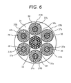
- a gas turbine combustor 2 is shown in Fig. 6 in which the center burner 33 is divided into a center burner's inner portion 33a and a center burner's outer portion 33b and the fuel system 51 for supplying fuel to the center burner 33 is divided into two systems for supplying fuel to the center burner's inner portion 33a and to the center burner's outer portion 33b.
- the rate of fuel supplied to the center burner's inner portion 33a can be made higher than the rate of fuel supplied to the center burner's outer portion 33b to keep the local flame temperature of the center portion high, and since the center portion is the source of flame holding, the loss of flame can be prevented. This can widen a range of the operating conditions of the center burner and allows greater flexibility in using the combustor.
- a gas turbine combustor and an operating method of the gas turbine combustor can be achieved to allow the gas turbine combustor equipped with a multi-burner to ensure combustion stability in the entire range of load conditions of the gas turbine and reduce the generation of unburned combustibles and an increase in the liner metal temperature at the same time in partial load conditions of the gas turbine.
- a gas turbine combustor 2 according to the second embodiment of the present invention will be described with reference to Figs. 7 and 8 .
- the gas turbine combustor 2 in the present embodiment has the same basic configuration and effect as the gas turbine combustor 2 in the first embodiment shown in Figs. 1 to 5 , thus redundant descriptions are omitted and only a difference will be explained.
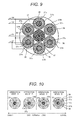
- Fig. 7 shows the gas turbine combustor 2 in the present embodiment; it is a front view of burners viewed from a chamber. Each burner is divided into sections to which fuel is supplied by the same fuel system.
- outer burners 37 installed in the peripheral region of the air hole plate 31 are, as shown in Fig. 7 , made up of three outer burners 37A including the outer burner 37A located at the top and the two specific outer burners 37A installed obliquely lower than the center burner 33 in either side (near the crossfire tubes 76) of the center burner 33 located in the center of the air hole plate 31, and three outer burners 37B installed in the other locations, that is, directly below and obliquely higher than the center burner 33.
- These outer burners 37A and outer burners 37B are disposed alternately.
- the inner fuel nozzles 25a disposed in the outer burner's inner portion 37a of the outer burner 37A disposed at the top are connected with a branched second fuel system 52.
- the gas turbine combustor 2 in the present embodiment is operated in the operation modes shown in Fig. 8 .
- a difference with those of the gas turbine combustor 2 in the first embodiment shown in Fig. 4 is when the gas turbine is switched from the operation mode A to the operation mode B, that is, from low load operation to partial load operation with increased load.
- the opening rate of the fuel rate adjusting valve 61 installed to the first fuel system 51 for supplying fuel to the center burner 33 but also the opening rate of the fuel rate adjusting valve 62 installed to the second fuel system 52 is controlled based on a control signal from the control device 100 to adjust the supply of fuel supplied to the fuel nozzles 25a in the outer burner's inner portions 37a in the inner side of the three outer burners 37A to burn the fuel nozzles 25a in the outer burner's inner portions 37a in the inner side of the three outer burners 37A; in this way, the operation mode is switched to the partial load operation mode B with increased load.
- Supplying fuel only to the center burner 33 and the outer burner's inner portions 37a located in the inner side of the three outer burners 37A such as above can limit the number of the fuel nozzles for supplying fuel to a small number so that a fuel air ratio can be increased locally in the outer burner's inner portions 37a of the three outer burner 37A.
- a deviation can be set for the rate of fuel supplied to the outer burner's inner portions 37a and the outer burner's inner portions 37b and the temperatures of combustion gas in the neighboring burners can be changed to change the combustion speed of flames formed.
- the three outer burners 37A and the three outer burners 37B are disposed alternately to configure the six outer burners 37, allowing more effective control of the amplification of pressure fluctuation.
- a gas turbine combustor and an operating method of the gas turbine combustor can be achieved to allow the gas turbine combustor equipped with a multi-burner to ensure combustion stability in the entire range of load conditions of the gas turbine and reduce the generation of unburned combustibles and an increase in the liner metal temperature at the same time in partial load conditions of the gas turbine.
- a gas turbine combustor 2 according to the third embodiment of the present invention will be described with reference to Figs. 9 and 10 .
- the gas turbine combustor 2 in the present embodiment has the same basic configuration and effect as the gas turbine combustor 2 in the first embodiment shown in Figs. 1 to 5 , thus redundant descriptions are omitted and only a difference will be explained.
- Fig. 9 is a gas turbine combustor 2 in the present embodiment; it is a front view of burners viewed from a chamber. Each burner is divided into sections to which fuel is supplied by the same fuel system.
- six outer burners 37 installed in the peripheral region of the air hole plate 31 are, as shown in Fig. 9 , made up of three outer burners 37A including the outer burner 37A located at the bottom and the specific two outer burners 37A installed obliquely lower than the center burner 33 in either side (near the crossfire tubes 76) of the center burner 33 located in the center of the air hole plate 31, and three outer burners 37B installed higher than the center burner 33, that is, directly above and obliquely higher than the center burner 33.
- the gas turbine combustor 2 in the present embodiment is operated in the operation modes shown in Fig. 10 .
- a difference with those of the gas turbine combustor 2 in the first embodiment shown in Fig. 4 is when the gas turbine is switched from the operation mode A to the operation mode B, that is, from low load operation to partial load operation with increased load.
- the opening rate of the fuel rate adjusting valve 61 installed to the first fuel system 51 for supplying fuel to the center burner 33 but also the opening rate of the fuel rate adjusting valve 62 installed to the second fuel system 52 is controlled based on a control signal from the control device 100 to adjust the supply of fuel supplied to the fuel nozzles 25a in the outer burner's inner portions 37a in the inner side of the three outer burners 37A to burn the fuel nozzles 25a in the outer burner's inner portions 37a in the inner side of the three outer burners 37A; in this way, the operation mode is switched to the partial load operation mode B with increased load.
- a gas turbine combustor and an operating method of the gas turbine combustor can be achieved to allow the gas turbine combustor equipped with a multi-burner to ensure combustion stability in the entire range of load conditions of the gas turbine and reduce the generation of unburned combustibles and an increase in the liner metal temperature at the same time in partial load conditions of the gas turbine.
- a gas turbine combustor 2 according to the fourth embodiment of the present invention will be described with reference to Figs. 11 and 12 .
- the gas turbine combustor 2 in the present embodiment has the same basic configuration and effect as the gas turbine combustor 2 in the first embodiment shown in Figs. 1 to 5 , thus redundant descriptions are omitted and only a difference will be explained.
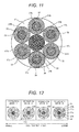
- Fig. 11 showing the gas turbine combustor 2 of the present embodiment is a front view of the burners viewed from the chamber. Each burner is divided into sections to which fuel is supplied by the same fuel system.
- six outer burners 37 installed in the peripheral region of the air hole plate 31 are, as shown in Fig. 11 , made up of two specific outer burners 37A installed obliquely lower than the center burner 33 in either side (near the crossfire tubes 76) of the center burner 33 located in the center of the air hole plate 31 and four outer burners 37B including the two outer burners 37B installed above and below the center burner 33 and the two outer burners 37B installed obliquely higher than the center burner 33.
- the burners in the gas turbine combustor 2 in the present embodiment including the center burner 33, the two outer burners 37A, and the four outer burners 37B each have air holes arranged in four circular rows and fuel nozzles disposed in four rows corresponding to the air holes.
- the air holes in the two rows from the center in the outer burners 37A are controlled as the same group and the air holes in the two rows from the center in the outer burners 37B are also controlled as the same group.
- the gas turbine combustor 2 in the present embodiment is operated in the operation modes shown in Fig. 12 in the same manner as the operation modes of the gas turbine combustor 2 in the first embodiment shown in Fig. 4 .
- the gas turbine combustor 2 in the present embodiment can increase the area of boundary between fuel and air by increasing the number of nozzles without enlarging the air holes and the fuel nozzles to promote the mixture of fuel and air. Then, uniform premixed combustion can be achieved to obtain low NOx combustion.
- the gas turbine combustor 2 in the present embodiment has two rows of air holes in the outer burner's inner portions 37a of the outer burners 37A and the outer burner's inner portions 37b of the outer burners 37B to enlarge the flame holding area, thus flames can be held stably.
- having the two rows of air holes in the outer burner's inner portions 37 of the outer burners 37A and the outer burner's inner portions 37b of the outer burners 37B will lower the local fuel air ratios in partial load conditions, but since the fuel rate of the entire gas turbine is increased and the fuel is burned diffusely, the discharge of unburned combustibles can be reduced.
- a gas turbine combustor and an operating method of the gas turbine combustor can be achieved to allow the gas turbine combustor equipped with a multi-burner to ensure combustion stability in the entire range of load conditions of the gas turbine and reduce the generation of unburned combustibles and an increase in the liner metal temperature at the same time in partial load conditions of the gas turbine.
- the present invention is applicable to a gas turbine combustor equipped with a multi-burner and an operating method of the gas turbine combustor.
Landscapes
- Engineering & Computer Science (AREA)
- Chemical & Material Sciences (AREA)
- Combustion & Propulsion (AREA)
- Mechanical Engineering (AREA)
- General Engineering & Computer Science (AREA)
- Gas Burners (AREA)
Abstract
Description
- The present invention relates to a gas turbine combustor and an operating method of the gas turbine combustor.
- There is a need for gas turbines to be lower in NOx from the perspective of environmental protection.
- One way to lower the NOx of a gas turbine combustor is a premixed combustor; in this case, there is a concern of a backfire phenomenon in which a flame enters a premixing device.
- Japanese Patent Laid-open No.
2003-148734 - In addition, Japanese Patent Laid-open No.
2011-075172 2003-148734 - {Patent Literature 1} Japanese Patent Laid-open No.
2003-148734 - {Patent Literature 2} Japanese Patent Laid-open No.
2011-075172 - A gas turbine needs to be operated stably in a wide range of operating conditions from ignition to full load operation. For this reason, a multi-burner with a plurality of burners has been widely adopted as a gas turbine combustor.
- While the above Japanese Patent Laid-open No.
2003-148734 2011-075172 - An object of the present invention is to provide a gas turbine combustor and an operating method of the gas turbine combustor to allow the gas turbine combustor equipped with a multi-burner to ensure combustion stability in the entire range of load conditions of the gas turbine and reduce the generation of unburned combustibles and an increase in liner metal temperature at the same time in partial load conditions of the gas turbine.
- A gas turbine combustor of the present invention comprising: a chamber for mixing and burning supplied fuel and supplied air to generate combustion gas; an air hole plate located in an upstream side of the chamber, forming a plurality of air holes for supplying the air; a plurality of fuel nozzles for supplying the fuel to the plurality of air holes formed in the air hole plate, wherein the air holes are disposed in the downstream side of the fuel nozzles that one of the fuel nozzles is paired with one of the air holes; and a plurality of burners made up of the plurality of air holes and the plurality of fuel nozzles in pairs, characterized in that, the plurality of burners are comprised a center burner disposed on an axis of the gas turbine combustor and a plurality of outer burners installed around the center burner, the center burner is fixed to a first fuel supply system for supplying the fuel to the fuel nozzles in the center burner, the plurality of outer burners is fixed to a second fuel supply system for supplying the fuel to the fuel nozzles in outer burner's inner portions which are inner regions of specific outer burners among the outer burners, the plurality of outer burners is fixed to a third fuel supply system for supplying the fuel to the fuel nozzles in outer burner's inner portions which are inner regions of outer burners other than the specific outer burners, the plurality of outer burners is fixed to a fourth fuel supply system for supplying the fuel to the fuel nozzles in outer burner's outer portions which are outer regions of the outer burners, wherein when a gas turbine is operated in a low load or partial load condition, the fuel is supplied to the fuel nozzles in the center burner or to the fuel nozzles in the center burner and in the outer burner's inner portions which are the inner regions of the specific outer burners among the plurality of outer burners through the first to the fourth fuel supply systems selected based on the operation condition of the gas turbine.
- An operating method of a gas turbine combustor of the present invention having a chamber for mixing and burning supplied fuel and supplied air to generate combustion gas; an air hole plate located in an upstream side of the chamber, forming a plurality of air holes for supplying the air; a plurality of fuel nozzles for supplying the fuel to the plurality of air holes formed in the air hole plate, wherein the air holes are disposed in a downstream side of the fuel nozzles that one of the fuel nozzles is paired with one of the air holes; and a plurality of burners made up of the plurality of air holes and the plurality of fuel nozzles in pairs, wherein the plurality of burners are comprised a center burner disposed on an axis of the gas turbine combustor and a plurality of outer burners installed around the center burner, the center burner is fixed to a first fuel supply system for supplying the fuel to the fuel nozzles in the center burner, the plurality of outer burners is fixed to a second fuel supply system for supplying the fuel to the fuel nozzles in outer burner's inner portions which are inner regions of specific outer burners among the outer burners, the plurality of outer burners is fixed to a third fuel supply system for supplying the fuel to the fuel nozzles in outer burner's inner portions which are inner regions of the outer burners other than the specific outer burners, and the plurality of outer burners is fixed to a fourth fuel supply system for supplying the fuel to the fuel nozzles in outer burner's outer portions which are outer regions of the outer burners, the operating method of a gas turbine combustor comprising the steps of: supplying the fuel through the first fuel supply system to the fuel nozzles disposed in the center burner to burn the chamber when a gas turbine is operated in a low load condition; supplying the fuel additionally through the second fuel supply system to the fuel nozzles disposed in the outer burner's inner portions which are the inner regions of the specific outer burners among the plurality of outer burners to burn the chamber when the gas turbine is operated in a partial load condition with load increased more than that of the low load gas turbine; supplying the fuel additionally through the third fuel supply system to the fuel nozzles disposed in the outer burner's inner portions which are the inner regions of all other outer burners among the plurality of outer burners except for the specific outer burners to burn the chamber when the gas turbine is operated in a partial load condition with load increased more than that of said partial load gas turbine; and supplying the fuel additionally through the fourth fuel supply system to the fuel nozzles disposed in the outer burner's outer portions which are the outer regions of all the outer burners to burn the chamber when the gas turbine is operated in a full load condition with load further increased.
- According to the present invention, a gas turbine combustor and an operating method of the gas turbine combustor can be achieved to allow the gas turbine combustor equipped with a multi-burner to ensure combustion stability in the entire range of load conditions of the gas turbine and reduce the generation of unburned combustibles and an increase in liner metal temperature at the same time in partial load conditions of the gas turbine.
-
- {
Fig. 1} Figure 1 is a system diagram of a plant showing a schematic structure of a gas turbine plant to which a gas turbine combustor according to the first embodiment of the present invention is applied. - {
Fig. 2} Figure 2 is a partial cross-sectional view showing a detailed configuration of a fuel supply portion made up of fuel nozzle headers, fuel nozzles and an air hole plate in the gas turbine combustor according to the first embodiment of the present invention. - {
Fig. 3} Figure 3 is a front view of the air hole plate, viewed from the chamber side, in the gas turbine combustor according to the first embodiment shown inFig. 2 . - {
Fig. 4} Figure 4 is an illustration of operation modes showing an example of a fuel staging method for the gas turbine combustor according to the first embodiment shown inFig. 2 . - {
Fig. 5} Figure 5 illustrates an example of a method of supplying fuel at ignition for the gas turbine combustor according to the first embodiment shown inFig. 1 . - {
Fig. 6} Figure 6 is a front view of a variation of the air hole plate, viewed from the chamber side, in the gas turbine combustor according to the first embodiment shown inFig. 1 . - {
Fig. 7} Figure 7 is a front view of an air hole plate, viewed from the chamber side, in a gas turbine combustor according to the second embodiment of the present invention. - {
Fig. 8} Figure 8 is an illustration of operation modes showing an example of a fuel staging method for the gas turbine combustor according to the second embodiment shown inFig. 7 . - {
Fig. 9} Figure 9 is a front view of an air hole plate, viewed from the chamber side, in a gas turbine combustor according to the third embodiment of the present invention. - {
Fig. 10} Figure 10 is an illustration of operation modes showing an example of a fuel staging method for the gas turbine combustor according to the third embodiment shown inFig. 9 . - {
Fig. 11} Figure 11 is a front view of an air hole plate, viewed from the chamber side, in a gas turbine combustor according to the fourth embodiment of the present invention. - {
Fig. 12} Figure 12 is an illustration of operation modes showing an example of a fuel staging method for the gas turbine combustor according to the fourth embodiment shown inFig. 11 . - Gas turbine combustors and operating methods of the gas turbine combustors according to the embodiments of the present invention will be described below with reference to accompanying drawings.
- A gas turbine combustor and an operating method of the gas turbine combustor according to the first embodiment of the present invention will be described with reference to
Figs. 1 to 3 . -
Figure 1 is a system diagram showing the entire structure of a gas turbine plant for power generation. - In a gas turbine plant 9 shown in
Fig. 1 , a gas turbine for power generation is made up of a compressor 1 for pressurizing suckedair 15 to generate high-pressure air 16, agas turbine combustor 2 for mixing and burninggas fuel 50 and the high-pressure air 16 generated by the compressor 1 to generate high-temperature combustion gas 18, aturbine 3 driven by the high-temperature combustion gas 18 generated in thegas turbine combustor 2, agenerator 8 for power generation rotated by the action of theturbine 3, and a shaft 7 for joining the compressor 1, theturbine 3 and thegenerator 8 together. - The
gas turbine combustor 2 is housed in acasing 4. The head portion of thegas turbine combustor 2 is provided with a multi-burner 6 made up of a plurality offuel nozzles 25, and the inside of thegas turbine combustor 2 in the downstream side of the multi-burner 6 is provided with an approximatelycylindrical combustor liner 10 for separating the high-pressure air and fuel gas. - A
chamber 5 is formed in thecombustor liner 10 to mix and burn the high-pressure air 16 and thegas fuel 50 to generate the high-temperature combustion gas 18. - An approximately
cylindrical flow sleeve 11 is disposed around the outer periphery of thecombustor liner 10, and the sleeve becomes an external wall forming an air passage for passing the high-pressure air. The diameter of theflow sleeve 11 is larger than that of thecombustor liner 10, and theflow sleeve 11 is disposed concentrically with thecombustor liner 10. - The downstream side of the
combustor liner 10 is atransition piece 12 for introducing the high-temperature combustion gas 18 generated in thechamber 5 of thegas turbine combustor 2 into theturbine 3. - A
flow sleeve 13 for surrounding thetransition piece 12 is disposed around the outer periphery of thetransition piece 12 in the downstream side of theflow sleeve 11. - The sucked
air 15 is pressurized by the compressor 1 and then becomes the high-pressure air 16. After the high-pressure air 16 fills thecasing 4, it flows into a space between thetransition piece 12 and theflow sleeve 13 for surrounding thetransition piece 12 to cool thetransition piece 12 from the external surface in the form of convection cooling. - Then, the high-
pressure air 16 passes through an annular passage formed between theflow sleeve 11 and thecombustor liner 10 to flow toward the head portion of thegas turbine combustor 2. The high-pressure air 16 is used for convection cooling of thecombustor liner 10 as it flows. - In addition, part of the high-
pressure air 16 flows into thecombustor liner 10 from numerous cooling holes provided to thecombustor liner 10 to be used for film cooling of thecombustor liner 10. - Out of the high-
pressure air 16, the remainingcombustion air 17 which was not used for the film cooling of thecombustor liner 10 flows into thechamber 5 fromnumerous air holes 32 provided in anair hole plate 31 located at the upstream side of thechamber 5 of thegas turbine combustor 2. - The
combustion air 17 flowed into thecombustor liner 10 from thenumerous air holes 32 is burned in thechamber 5 formed in thecombustor liner 10 along with fuel ejected from a plurality offuel nozzles 25 of the multi-burner 6 to generate the high-temperature combustion gas 18. - The high-
temperature combustion gas 18 generated by the burning in thechamber 5 in thecombustor liner 10 is supplied to theturbine 3 through thetransition piece 12 to drive theturbine 3. - After driving the
turbine 3, the high-temperature combustion gas 18 is discharged from theturbine 3 asexhaust gas 19. - The drive force obtained by the
turbine 3 is transferred to the compressor 1 and thegenerator 8 through the shaft 7. Part of the drive force obtained by theturbine 3 drives the compressor 1 to pressurize air to generate high-pressure air. The other part of the drive force obtained by theturbine 3 rotates thegenerator 8 to generate power. - The multi-burner 6 made up of the plurality of
fuel nozzles 25 in thegas turbine combustor 2 is, as shown inFig. 1 , fixed with four fuel systems for supplying thefuel 50, which are afirst fuel system 51 to afourth fuel system 54. - The
first fuel system 51 to thefourth fuel system 54 are provided with fuelrate adjusting valves 61 to 64 respectively, and the flow rates of thefuel 50 supplied through thefirst fuel system 51 to thefourth fuel system 54 are adjusted by changing the opening rate of the respective fuelrate adjusting valves 61 to 64 based on a control signal from acontrol device 100 to control the output of the gas turbine plant 9. - Additionally, the upstream side of the branching point where the system is branched into four systems of the
first fuel system 51 to thefourth fuel system 54 is provided with a fuel cutoff valve 60 for cutting off the supply of thefuel 50. -
Fig. 2 is a cross-sectional view showing the detailed configuration of the disk-shapedair hole plate 31, a multi-burner 6 having the plurality offuel nozzles 25, andfuel nozzle headers 23 constituting a fuel supply portion of thegas turbine combustor 2 according to the present embodiment, andFig. 3 is the front view of thegas turbine combustor 2 in which theair hole plate 31 is viewed from thechamber 5. The detail of the multi-burner 6 of thegas turbine combustor 2 will be described below with reference toFigs. 2 and 3 . - As shown in
Figs. 2 and 3 , in thegas turbine combustor 2 of the present embodiment, the multi-burner 6 provided with the plurality offuel nozzles 25 is made up of acenter burner 33 disposed corresponding to the center of the disk-shapedair hole plate 31 and sixouter burners 37 disposed away from each other around thecenter burner 33 between the center and the outer periphery of theair hole plate 31. - The
center burner 33 and theouter burners 37 are each installed with thenumerous fuel nozzles 25 constituting thesecenter burner 33 andouter burners 37 and thefuel nozzle headers 23 for distributing fuel to thefuel nozzles 25 in the upstream side of thefuel nozzles 25. - Then, the
numerous air holes 32 which pass air and the fuel ejected from thefuel nozzles 25 for ejecting them to thechamber 5 of thegas turbine combustor 2 are provided to theair hole plate 31 which is installed in the downstream side of thefuel nozzles 25 and the upstream side of thechamber 5. - Furthermore, as shown in the front view of the
gas turbine combustor 2 inFig. 3 , thenumerous air holes 32 formed in theair hole plate 31 correspond one-to-one with thenumerous fuel nozzles 25 provided to each of thecenter burner 33 and the sixouter burners 37 around thecenter burner 33; theair hole plate 31 is installed so as to partition thechamber 5. - In other words, the
numerous air holes 32 formed in theair hole plate 31 are made up of a plurality ofair holes 32 in the first row in the center, a plurality ofair holes 32 in the second row around the first row, and a plurality ofair holes 32 in the third row around the second row in the center region of theair hole plate 31 corresponding to thecenter burner 33; the three rows ofair holes 32 are arranged concentrically in the center region of theair hole plate 31. - In the same manner, six areas in the peripheral region of the
air hole plate 31 corresponding to the sixouter burners 37 each have a plurality ofair holes 32 in the first row in the center, a plurality ofair holes 32 in the second row around the first row, and a plurality ofair holes 32 in the third row around the second row; the three rows ofair holes 32 are formed concentrically in each area in the peripheral region of theair hole plate 31. - Furthermore, the
numerous air holes 32 formed in each area in the peripheral region of theair hole plate 31 corresponding to thenumerous fuel nozzles 25 installed in each of thecenter burner 33 and theouter burners 37 are formed diagonally with respect to the axis of thechamber 5 so that each air hole has an angle of traverse to thechamber 5 of thegas turbine combustor 2. - The
numerous air holes 32 formed in theair holes plate 31 cause swirl flows 40 to be formed, which are mixed flows of fuel and air formed in thechamber 5 of thegas turbine combustor 2 in the downstream side of thecenter burner 33 and theouter burners 37, and the swirl flows 40 generate recirculation flows 41 which holdflames 42 formed by burning the fuel in thechamber 5 of thegas turbine combustor 2. - The six
outer burners 37 installed to thegas turbine combustor 2 in the present embodiment each have numerousinner fuel nozzles 25a and numerousouter fuel nozzles 25b, and thesecond fuel system 52 to thefourth fuel system 54 are separately installed to supply fuel to theinner fuel nozzles 25a and theouter fuel nozzles 25b. - The
center burner 33 disposed in the center region of theair hole plate 31 in thegas turbine combustor 2 of the present embodiment has thenumerous fuel nozzles 25, to which fuel is supplied by thefirst fuel system 51 connected to thecenter burner 33. - The six
outer burners 37 installed in the peripheral region of theair hole plate 31 each have theinner fuel nozzles 25a, as shown inFig. 2 , corresponding to the plurality ofair holes 32 in the first row in the center of each area in the peripheral region of theair hole plate 31 and theouter fuel nozzles 25b corresponding to the plurality ofair holes 32 in the second and the third rows in each area in the peripheral region of theair hole plate 31, and thesecond fuel system 52 to thefourth fuel system 54 are connected to theinner fuel nozzles 25a and theouter fuel nozzles 25b separately. - In other words, the
second fuel system 52 or thethird fuel system 53 is connected to theinner fuel nozzles 25a of theouter burners 37 corresponding to the plurality ofair holes 32 in the first row in the center of each area in the peripheral region of theair hole plate 31, and the branchedfourth fuel system 54 is connected to theouter fuel nozzles 25b of theouter burners 37 corresponding to the plurality ofair holes 32 in the second and the third rows in each area in the peripheral region of theair hole plate 31. - In the
gas turbine combustor 2 in the present embodiment, the sixouter burners 37 installed in the peripheral region of theair hole plate 31 are, as shown inFig. 3 , made up of two specificouter burners 37A which are installed obliquely lower than thecenter burner 33 in either side (nearcrossfire tubes 76 to be described later) of thecenter burner 33 located in the center of theair hole plate 31, and the other fourouter burners 37B installed above, below, and obliquely higher than thecenter burner 33. - The two specific
outer burners 37A are divided into a group of outer burner'sinner portions 37a in the inner side and a group of outer burner'souter portions 38 around the outer burner'sinner portions 37a. - In the same manner, the four
outer burners 37B are divided into a group of outer burner'sinner portions 37b in the inner side and a group of outer burner'souter portions 38 around the outer burner'sinner portions 37b. - The
second fuel system 52 is connected to theinner fuel nozzles 25a disposed in the outer burner'sinner portions 37a of the twoouter burners 37A, and thethird fuel system 53 is connected to theinner fuel nozzles 25a disposed in the outer burner'sinner portions 37b of the fourouter burners 37B. - In addition, the
fourth fuel system 54 is branched and connected to theouter fuel nozzles 25b disposed in the outer burner'souter portions 38 of the two specificouter burners 37A and the fourouter burners 37B respectively. - Next, an operating method of the
gas turbine combustor 2 according to the present embodiment will be described with reference toFigs. 1 to 4 . - The
gas turbine combustor 2 in the present embodiment is operated in operation modes shown inFig. 4 . That is, in the operating method of thegas turbine combustor 2 according to the present embodiment, the opening rates of the fuelrate adjusting valves 61 to 64 installed to thefirst fuel system 51 to thefourth fuel system 54 are adjusted to control the supply of fuel according to an increase in the load of the gas turbine based on an operation mode command outputted from thecontrol device 100 shown inFig. 1 . - For example, when the gas turbine is operated in a low load operation mode A where the
center burner 33 of the multi-burner provided to thegas turbine combustor 2 is burned alone, the opening rate of the fuelrate adjusting valve 61 installed to thefirst fuel system 51 is adjusted to control the supply of fuel based on a control signal from thecontrol device 100 and only thecenter burner 33 of thegas turbine combustor 2 is burned by itself. - Next, when the gas turbine is switched from the low load operation to partial load operation with increased load, the low load operation mode A where the
center burner 33 in the multi-burner provided to thegas turbine combustor 2 is burned alone is switched to a partial load operation mode B where thefuel nozzles 25a in the outer burner'sinner portions 37a in the inner side of the two specificouter burners 37A among theouter burners 37 are burned; in this case, not only the opening rate of the fuelrate adjusting valve 61 installed to thefirst fuel system 51 for supplying fuel to thecenter burner 33 but also the opening rate of the fuelrate adjusting valve 62 installed to thesecond fuel system 52 is controlled based on a control signal from thecontrol device 100 to adjust the supply of fuel supplied to thefuel nozzles 25a in the outer burner'sinner portions 37a in the inner side of the twoouter burners 37A to burn thefuel nozzles 25a in the outer burner'sinner portions 37a in the inner side of the twoouter burners 37A; in this way, the operation mode is switched to the partial load operation mode B with increased load. - Supplying fuel only to the
center burner 33 and the outer burner'sinner portions 37a in the inner side of the twoouter burners 37A can limit the number of the fuel nozzles for supplying fuel to a small number, so that a fuel air ratio can be increased locally in the outer burner'sinner portions 37a of the twoouter burners 37A. - This causes diffusion flames to be formed in the
chamber 5 of thegas turbine combustor 2, thereby reducing the generation of unburned combustibles even when a large amount of air is flowing around. - Furthermore, since air is flowing around the diffusion flames from the outer burner's
outer portions 38 in the outer side of the twoouter burners 37A, it is possible to prevent the flames formed in thechamber 5 from directly interfering with the liner, and an increase in the metal temperature can be prevented even under a condition that the local fuel air ratio gets high immediately before the operation mode is switched to an operation mode C. - In the operating method of the gas turbine combustor 2 in the present embodiment, when the load of the gas turbine is further increased, the operation mode B is switched to a partial load operation mode C where fuel is supplied not only to the center burner 33 and the outer burner's inner portions 37a of the two outer burners 37A but also to the fuel nozzles 25a in the outer burner's inner portions 37b in the inner side of the four outer burners 37B to be burned; in this case, in addition to controlling the opening rates of the fuel rate adjusting valve 61 installed to the first fuel system 51 for supplying fuel to the center burner 33 and the fuel rate adjusting valve 62 installed to the second fuel system 52 for supplying fuel to the fuel nozzles 25a in the outer burner's inner portions 37a in the inner side of the two outer burner 37A, the opening rate of the fuel rate adjusting valve 63 installed to the third fuel system 53 for supplying fuel to the fuel nozzles 25a in the outer burner's inner portions 37b in the inner side of the four outer burners 37B is controlled based on a control signal from the control device 100 to adjust the supply of fuel to be burned, and the operation mode is switched to the partial load operation mode C with increased load to supply the fuel to the center burner 33, the outer burner's inner portions 37a of the two outer burners 37A, and the outer burner's inner portions 37b of the four outer burners 37B to be burned.
- In this operation mode C, in the same manner as the operation mode B, the fuel is supplied only to the
center burner 33, the outer burner'sinner portions 37a in the inner side of the twoouter burners 37A, and the outer burner'sinner portions 37b in the inner side of the fourouter burners 37B to be burned, which can limit the number of the fuel nozzles for supplying fuel to a small number, so that the fuel air ratio can be increased locally in the outer burner'sinner portions 37a of the twoouter burners 37A and the outer burner'sinner portions 37b of the fourouter burners 37B. - This can increase the fuel air ratio locally in the outer burners, and stable diffusion flames can be formed in the
chamber 5 of thegas turbine combustor 2 to reduce the generation of unburned combustibles. - Furthermore, since air is flowing around the diffusion flames from the outer burner's
outer portions 38 in the outer side of the twoouter burner 37A and the four outer burners 38B, it is possible to prevent the flames formed in thechamber 5 from directly interfering with the liner, and an increase in the metal temperature can be prevented even under a condition that the local fuel air ratio gets high immediately before the operation mode is switched to an operation mode D. - In the operating method of the
gas turbine combustor 2 in the present embodiment, when the load of the gas turbine is further increased to be full load operation, the operation mode C is switched to a full load operation mode D where fuel is supplied not only to thecenter burner 33, thefuel nozzles 25a in the outer burner'sinner portions 37a of the twoouter burners 37A, and thefuel nozzles 25a in the outer burner'sinner portions 37b of the fourouter burners 37B but also to thefuel nozzles 25b in the outer burner'souter portions 38 of the twoouter burner 37A and the fourouter burners 37B through thefourth fuel system 54 to be burned. - When the partial load operation mode C is switched to the full load operation mode D, in addition to controlling the opening ratios of the fuel rate adjusting valve 61 installed to the first fuel system 51 for supplying fuel to the center burner 33, the fuel rate adjusting valve 62 installed to the second fuel system 52 for supplying fuel to the fuel nozzles 25a in the outer burner's inner portions 37a in the inner side of the two outer burners 37A, and the fuel rate adjusting valve 63 installed to the third fuel system 53 for supplying fuel to the fuel nozzles 25a in the outer burner's inner portions 37b in the inner side of the four outer burners 37B, the opening ratio of the fuel rate adjusting valve 64 installed to the fourth fuel system 54 for supplying fuel to the fuel nozzles 25b in the outer burner's outer portions 38 in the outer side of the two outer burners 37A and the four outer burners 37B are controlled based on a control signal from the control device 100 to adjust the supply of fuel to be burned; in this way, the operation mode is switched to the full load operation mode D with increased load, and gas turbine is operated in full load by supplying the fuel to the center burner 33, the outer burner's inner portions 37a of the two outer burners 37A, the outer burner's inner portions 37b of the four outer burner 37B, and the outer burner's outer portions 38 of the two outer burners 37A and the four outer burners 37B to be burned.
- As described above, in the operating method of the
gas turbine combustor 2 in the present embodiment, the operation modes A, B, and C are used in lower load conditions than the operation mode D where fuel is supplied to all thefuel systems 51 to 54; and in these modes, thecenter burner 33, the outer burner'sinner portions 37a of the twoouter burner 37A, and the outer burner'sinner portions 37b of the fourouter burner 37B among the sixouter burners 37 are combined to be used so that the generation of unburned combustibles and an increase in the liner metal temperature can be reduced. - Next, an embodiment of an ignition method in the above operating method of the
gas turbine combustor 2 according to the present embodiment will be described with reference to a schematic diagram shown inFig. 5 . - In the schematic diagram of
Fig. 5 showing the ignition method of thegas turbine combustor 2, thegas turbine combustor 2 in the present embodiment includes a plurality ofgas turbine combustors 2 installed in the outer periphery of the gas turbine; among which one of combustors, agas turbine combustor 2a is provided with anignition plug 77, and thegas turbine combustor 2a and agas turbine combustor 2b installed adjacent to thegas turbine combustor 2a are connected by acrossfire tube 76 to propagate a flame. - In the
gas turbine combustor 2a according to the present embodiment, out of the sixouter burners 37 installed around onecenter burner 33, the twoouter burners 37A disposed obliquely lower than thecenter burner 33 in either side each have the outer burner'sinner portion 37a in the inner side and the outer burner'souter portion 38 in the outer side. - Furthermore, out of the six
outer burners 37 installed around thecenter burner 33, the remaining fourouter burners 37B other than the twoouter burners 37A each have the outer burner'sinner portion 37b in the inner side and the outer burner'souter portion 38 in the outer side. - The two
outer burners 37A provided with the outer burner'sinner portion 37a are each disposed to be closest to therespective crossfire tube 76 among the plurality ofouter burners 37. - At the ignition of the
gas turbine combustors 2, fuel is supplied to thecenter burner 33 and the outer burner'sinner portions 37a of the twoouter burners 37A in themulti-burner 6 provided in thegas turbine combustor 2a having theignition plug 77, and theignition plug 77 is ignited to burn the fuel supplied to thecenter burner 33 and thefuel nozzles 25a in the outer burner'sinner portions 37a of theouter burners 37A; in this way, flames are formed in thecenter burner 33 and the outer burner'sinner portions 37a of the twoouter burner 37A located near thecrossfire tubes 76. - Then, when the inner pressure of the ignited
gas turbine combustor 2a is increased and flames are formed near thecrossfire tubes 76, high-temperature combustion gas generated in thegas turbine combustor 2a flows into thegas turbine combustors 2b adjacent to thegas turbine combustor 2a via thecrossfire tubes 76. - The configuration of the
outer burners 37 made up of acenter burner 33, twoouter burners 37A installed near thecrossfire tubes 76, and fourouter burners 37B in themulti-burner 6 in the adjacentgas turbine combustor 2b is the same as that of theouter burners 37 made up of thecenter burner 33, the twoouter burner 37A, and the fourouter burners 37B in themulti-burner 6 in thegas turbine combustor 2a. So, in thegas turbine combustor 2b also, the fuel supplied to thefuel nozzles 25a in the outer burner'sinner portions 37a of the twoouter burners 37A located near thecrossfire tubes 76 is easily ignited by the high-temperature combustion gas flowed from thegas turbine combustor 2a via thecrossfire tube 76 to form flames in thecenter burner 33 and the outer burner'sinner portions 37a of theouter burners 37A. - Then, when the inner pressure of the ignited
gas turbine combustor 2b is increased and flames are formed near thecrossfire tubes 76, the high-temperature combustion gas generated in thegas turbine combustor 2b flows into agas turbine combustor 2 adjacent to thegas turbine combustor 2b via thecrossfire tube 76; in this way, fire can be propagated further to the othergas turbine combustors 2. - As another example of the gas turbine combustor of the present embodiment, a
gas turbine combustor 2 is shown inFig. 6 in which thecenter burner 33 is divided into a center burner'sinner portion 33a and a center burner'souter portion 33b and thefuel system 51 for supplying fuel to thecenter burner 33 is divided into two systems for supplying fuel to the center burner'sinner portion 33a and to the center burner'souter portion 33b. - In this case, even when the local fuel air ratio of the
center burner 33 is low, the rate of fuel supplied to the center burner'sinner portion 33a can be made higher than the rate of fuel supplied to the center burner'souter portion 33b to keep the local flame temperature of the center portion high, and since the center portion is the source of flame holding, the loss of flame can be prevented. This can widen a range of the operating conditions of the center burner and allows greater flexibility in using the combustor. - According to the present embodiment, a gas turbine combustor and an operating method of the gas turbine combustor can be achieved to allow the gas turbine combustor equipped with a multi-burner to ensure combustion stability in the entire range of load conditions of the gas turbine and reduce the generation of unburned combustibles and an increase in the liner metal temperature at the same time in partial load conditions of the gas turbine.
- A
gas turbine combustor 2 according to the second embodiment of the present invention will be described with reference toFigs. 7 and 8 . - The
gas turbine combustor 2 in the present embodiment has the same basic configuration and effect as thegas turbine combustor 2 in the first embodiment shown inFigs. 1 to 5 , thus redundant descriptions are omitted and only a difference will be explained. -
Fig. 7 shows thegas turbine combustor 2 in the present embodiment; it is a front view of burners viewed from a chamber. Each burner is divided into sections to which fuel is supplied by the same fuel system. - In the
gas turbine combustor 2 in the present embodiment shown inFig. 7 , sixouter burners 37 installed in the peripheral region of theair hole plate 31 are, as shown inFig. 7 , made up of threeouter burners 37A including theouter burner 37A located at the top and the two specificouter burners 37A installed obliquely lower than thecenter burner 33 in either side (near the crossfire tubes 76) of thecenter burner 33 located in the center of theair hole plate 31, and threeouter burners 37B installed in the other locations, that is, directly below and obliquely higher than thecenter burner 33. Theseouter burners 37A andouter burners 37B are disposed alternately. - In the present embodiment, the
inner fuel nozzles 25a disposed in the outer burner'sinner portion 37a of theouter burner 37A disposed at the top are connected with a branchedsecond fuel system 52. - The
gas turbine combustor 2 in the present embodiment is operated in the operation modes shown inFig. 8 . A difference with those of thegas turbine combustor 2 in the first embodiment shown inFig. 4 is when the gas turbine is switched from the operation mode A to the operation mode B, that is, from low load operation to partial load operation with increased load. - In this case, not only the opening rate of the fuel
rate adjusting valve 61 installed to thefirst fuel system 51 for supplying fuel to thecenter burner 33 but also the opening rate of the fuelrate adjusting valve 62 installed to thesecond fuel system 52 is controlled based on a control signal from thecontrol device 100 to adjust the supply of fuel supplied to thefuel nozzles 25a in the outer burner'sinner portions 37a in the inner side of the threeouter burners 37A to burn thefuel nozzles 25a in the outer burner'sinner portions 37a in the inner side of the threeouter burners 37A; in this way, the operation mode is switched to the partial load operation mode B with increased load. - Supplying fuel only to the
center burner 33 and the outer burner'sinner portions 37a located in the inner side of the threeouter burners 37A such as above can limit the number of the fuel nozzles for supplying fuel to a small number so that a fuel air ratio can be increased locally in the outer burner'sinner portions 37a of the threeouter burner 37A. - This causes diffusion flames to be formed in the
chamber 5 of thegas turbine combustor 2, thereby reducing the generation of unburned combustibles even when a large amount of air is flowing around. - Furthermore, since air is flowing around the diffusion flames from the outer burner's
outer portions 38 located in the outer side of the threeouter burners 37A, it is possible to prevent the flames formed in thechamber 5 from directly interfering with the liner, and an increase in the metal temperature can be prevented even under a condition that the local fuel air ratio gets high immediately before the operation mode is switched to an operation mode C. - Moreover, in the
gas turbine combustor 2 in the present embodiment at the occurrence of combustion dynamics, a deviation can be set for the rate of fuel supplied to the outer burner'sinner portions 37a and the outer burner'sinner portions 37b and the temperatures of combustion gas in the neighboring burners can be changed to change the combustion speed of flames formed. - This will shift fluctuating frequencies so that the amplification of pressure fluctuation in the entire
gas turbine combustor 2 can be prevented. In thegas turbine combustor 2 in the present embodiment, the threeouter burners 37A and the threeouter burners 37B are disposed alternately to configure the sixouter burners 37, allowing more effective control of the amplification of pressure fluctuation. - According to the present embodiment, a gas turbine combustor and an operating method of the gas turbine combustor can be achieved to allow the gas turbine combustor equipped with a multi-burner to ensure combustion stability in the entire range of load conditions of the gas turbine and reduce the generation of unburned combustibles and an increase in the liner metal temperature at the same time in partial load conditions of the gas turbine.
- A
gas turbine combustor 2 according to the third embodiment of the present invention will be described with reference toFigs. 9 and 10 . - The
gas turbine combustor 2 in the present embodiment has the same basic configuration and effect as thegas turbine combustor 2 in the first embodiment shown inFigs. 1 to 5 , thus redundant descriptions are omitted and only a difference will be explained. -
Fig. 9 is agas turbine combustor 2 in the present embodiment; it is a front view of burners viewed from a chamber. Each burner is divided into sections to which fuel is supplied by the same fuel system. - In the
gas turbine combustor 2 in the present embodiment shown inFig. 9 , sixouter burners 37 installed in the peripheral region of theair hole plate 31 are, as shown inFig. 9 , made up of threeouter burners 37A including theouter burner 37A located at the bottom and the specific twoouter burners 37A installed obliquely lower than thecenter burner 33 in either side (near the crossfire tubes 76) of thecenter burner 33 located in the center of theair hole plate 31, and threeouter burners 37B installed higher than thecenter burner 33, that is, directly above and obliquely higher than thecenter burner 33. - The
gas turbine combustor 2 in the present embodiment is operated in the operation modes shown inFig. 10 . A difference with those of thegas turbine combustor 2 in the first embodiment shown inFig. 4 is when the gas turbine is switched from the operation mode A to the operation mode B, that is, from low load operation to partial load operation with increased load. - In this case, not only the opening rate of the fuel
rate adjusting valve 61 installed to thefirst fuel system 51 for supplying fuel to thecenter burner 33 but also the opening rate of the fuelrate adjusting valve 62 installed to thesecond fuel system 52 is controlled based on a control signal from thecontrol device 100 to adjust the supply of fuel supplied to thefuel nozzles 25a in the outer burner'sinner portions 37a in the inner side of the threeouter burners 37A to burn thefuel nozzles 25a in the outer burner'sinner portions 37a in the inner side of the threeouter burners 37A; in this way, the operation mode is switched to the partial load operation mode B with increased load. - Supplying fuel only to the
center burner 33 and the outer burner'sinner portions 37a in the inner side of the threeouter burners 37A such as this can further reduce the generation of unburned combustibles since flames are formed close to each other and cooling of the frames by the surrounding air is decreased. - According to the present embodiment, a gas turbine combustor and an operating method of the gas turbine combustor can be achieved to allow the gas turbine combustor equipped with a multi-burner to ensure combustion stability in the entire range of load conditions of the gas turbine and reduce the generation of unburned combustibles and an increase in the liner metal temperature at the same time in partial load conditions of the gas turbine.
- A
gas turbine combustor 2 according to the fourth embodiment of the present invention will be described with reference toFigs. 11 and 12 . - The
gas turbine combustor 2 in the present embodiment has the same basic configuration and effect as thegas turbine combustor 2 in the first embodiment shown inFigs. 1 to 5 , thus redundant descriptions are omitted and only a difference will be explained. - The gas turbine combustor according to the fourth embodiment of the present invention is shown in
Fig. 11. Fig. 11 showing thegas turbine combustor 2 of the present embodiment is a front view of the burners viewed from the chamber. Each burner is divided into sections to which fuel is supplied by the same fuel system. - In the
gas turbine combustor 2 in the present embodiment shown inFig. 11 , sixouter burners 37 installed in the peripheral region of theair hole plate 31 are, as shown inFig. 11 , made up of two specificouter burners 37A installed obliquely lower than thecenter burner 33 in either side (near the crossfire tubes 76) of thecenter burner 33 located in the center of theair hole plate 31 and fourouter burners 37B including the twoouter burners 37B installed above and below thecenter burner 33 and the twoouter burners 37B installed obliquely higher than thecenter burner 33. - Furthermore, the burners in the
gas turbine combustor 2 in the present embodiment including thecenter burner 33, the twoouter burners 37A, and the fourouter burners 37B each have air holes arranged in four circular rows and fuel nozzles disposed in four rows corresponding to the air holes. Among the air holes, the air holes in the two rows from the center in theouter burners 37A are controlled as the same group and the air holes in the two rows from the center in theouter burners 37B are also controlled as the same group. - The
gas turbine combustor 2 in the present embodiment is operated in the operation modes shown inFig. 12 in the same manner as the operation modes of thegas turbine combustor 2 in the first embodiment shown inFig. 4 . - While a gas turbine combustor for a high-output gas turbine tends to be large in size, the
gas turbine combustor 2 in the present embodiment can increase the area of boundary between fuel and air by increasing the number of nozzles without enlarging the air holes and the fuel nozzles to promote the mixture of fuel and air. Then, uniform premixed combustion can be achieved to obtain low NOx combustion. - When the size of one burner is enlarged and the number of rows is increased, having only the center row as a flame holding point may cause instability in holding flames.
- However, the
gas turbine combustor 2 in the present embodiment has two rows of air holes in the outer burner'sinner portions 37a of theouter burners 37A and the outer burner'sinner portions 37b of theouter burners 37B to enlarge the flame holding area, thus flames can be held stably. - As in the
gas turbine combustor 2 in the present embodiment, having the two rows of air holes in the outer burner'sinner portions 37 of theouter burners 37A and the outer burner'sinner portions 37b of theouter burners 37B will lower the local fuel air ratios in partial load conditions, but since the fuel rate of the entire gas turbine is increased and the fuel is burned diffusely, the discharge of unburned combustibles can be reduced. - According to the present embodiment, a gas turbine combustor and an operating method of the gas turbine combustor can be achieved to allow the gas turbine combustor equipped with a multi-burner to ensure combustion stability in the entire range of load conditions of the gas turbine and reduce the generation of unburned combustibles and an increase in the liner metal temperature at the same time in partial load conditions of the gas turbine.
- The present invention is applicable to a gas turbine combustor equipped with a multi-burner and an operating method of the gas turbine combustor.
- Features, components and specific details of the structures of the above-described embodiments may be exchanged or combined to form further embodiments optimized for the respective application. As far as those modifications are readily apparent for an expert skilled in the art they shall be disclosed implicitly by the above description without specifying explicitly every possible combination, for the sake of conciseness of the present description.
Claims (6)
- A gas turbine combustor comprising: a chamber (5) for mixing and burning supplied fuel (50) and supplied air (16) to generate combustion gas (18);
an air hole plate (31) located in an upstream side of the chamber (5), forming a plurality of air holes (32) for supplying the air (16);
a plurality of fuel nozzles (25) for supplying the fuel (50) to the plurality of air holes (32) formed in the air hole plate (31),
wherein the air holes (32) are disposed in the downstream side of the fuel nozzles (25) that one of the fuel nozzles (25) is paired with one of the air holes (32); and
a plurality of burners (6) made up of the plurality of air holes (32) and the plurality of fuel nozzles (25) in pairs,
characterized in that,
the plurality of burners (6) are comprised a center burner (33) disposed on an axis of the gas turbine combustor (2) and a plurality of outer burners (37) installed around the center burner (33),
the center burner (33) is fixed to a first fuel supply system (51) for supplying the fuel to the fuel nozzles (25) in the center burner (33),
the plurality of outer burners (37) is fixed to a second fuel supply system (52) for supplying the fuel to the fuel nozzles (25) in outer burner's inner portions (37a; 37b) which are inner regions of specific outer burners (37) among the outer burners (37),
the plurality of outer burners (37) is fixed to a third fuel supply system (53) for supplying the fuel to the fuel nozzles (25) in outer burner's inner portions (37a; 37b) which are inner regions of outer burners (37) other than the specific outer burners (37),
the plurality of outer burners (37) is fixed to a fourth fuel supply system (54) for supplying the fuel to the fuel nozzles (25) in outer burner's outer portions (38) which are outer regions of the outer burners (37),
wherein when a gas turbine (9) is operated in a low load or partial load condition, the fuel is supplied to the fuel nozzles (25) in the center burner (33) or to the fuel nozzles (25) in the center burner (33) and in the outer burner's inner portions (37a; 37b) which are the inner regions of the specific outer burners (37) among the plurality of outer burners (37) through the first to the fourth fuel supply systems selected based on the operation condition of the gas turbine (9). - The gas turbine combustor according to claim 1,
wherein the plurality of outer burners (37) are arranged in two groups of the specific outer burners (37) having first outer burner's inner portions (37a; 37b) supplied with the fuel through the second fuel supply system and the other outer burners (37) having second outer burner's inner portions (37a; 37b) supplied with the fuel through the third fuel supply system (53),
every one of the plurality of outer burners (37) has the outer burner's outer portion (38) in the outer side of the outer burner (37), and the outer burner's outer portions (38) make up a group to be supplied with the fuel through the fourth fuel supply system (54). - The gas turbine combustor according to claim 2,
wherein the specific outer burners (37) having the first outer burner's inner portions (37a; 37b) supplied with the fuel (50) through the second fuel supply system (52) are the outer burners (37) disposed near crossfire tubes connecting neighboring gas turbine combustors (2) among the plurality of outer burners (37) installed. - The gas turbine combustor according to claim 2 or 3, wherein the specific outer burners (37) having the first outer burner's inner portions (37a; 37b) supplied with the fuel (50) through the second fuel supply system (52) and the other outer burners (37) having the second outer burner's inner portions (37a; 37b) supplied with the fuel through the third fuel supply system (53) are disposed alternately.
- The gas turbine combustor according to at least one of claims 2 to 4,
wherein a plurality of the gas turbine combustors (2) are installed, and
when the gas turbine combustors (2) are ignited, the fuel (50) is supplied to the center burner (33) installed to the gas turbine combustor (2) to be ignited and the outer burner's inner portions (37a; 37b) which are the inner regions of the outer burners (37) disposed near the crossfire tubes connecting the gas turbine combustor (2) to be ignited and the gas turbine combustors (2) adjacent to the gas turbine combustor (2) to be ignited. - An operating method of a gas turbine combustor having a chamber (5) for mixing and burning supplied fuel (50) and supplied air (16) to generate combustion gas (18); an air hole plate (31) located in an upstream side of the chamber (5), forming a plurality of air holes (32) for supplying the air (16); a plurality of fuel nozzles (25) for supplying the fuel (50) to the plurality of air holes (32) formed in the air hole plate (31), wherein the air holes (32) are disposed in a downstream side of the fuel nozzles (25) that one of the fuel nozzles (25) is paired with one of the air holes (32); and a plurality of burners (6) made up of the plurality of air holes (32) and the plurality of fuel nozzles (25) in pairs, wherein the plurality of burners (6) are comprised a center burner (33) disposed on an axis of the gas turbine combustor (2) and a plurality of outer burners (37) installed around the center burner (33),
the center burner (33) is fixed to a first fuel supply system (51) for supplying the fuel (50) to the fuel nozzles (25) in the center burner (33),
the plurality of outer burners (37) is fixed to a second fuel supply system (52) for supplying the fuel (50) to the fuel nozzles (25) in outer burner's inner portions (37a; 37b) which are inner regions of specific outer burners (37) among the outer burners (37),
the plurality of outer burners (37) is fixed to a third fuel supply system (53) for supplying the fuel to the fuel nozzles (25) in outer burner's inner portions (37a; 37b) which are inner regions of the outer burners (37) other than the specific outer burners (37), and
the plurality of outer burners (37) is fixed to a fourth fuel supply system (54) for supplying the fuel to the fuel nozzles (25) in outer burner's outer portions (38) which are outer regions of the outer burners (37),
the operating method of a gas turbine combustor comprising the steps of:supplying the fuel (50) through the first fuel supply system (51) to the fuel nozzles (25) disposed in the center burner (33) to burn the chamber (5) when a gas turbine (9) is operated in a low load condition;supplying the fuel additionally through the second fuel supply system (52) to the fuel nozzles (25) disposed in the outer burner's inner portions (37a; 37b) which are the inner regions of the specific outer burners (37) among the plurality of outer burners (37) to burn the chamber (5) when the gas turbine (9) is operated in a partial load condition with load increased more than that of the low load gas turbine (9);supplying the fuel additionally through the third fuel supply system (53) to the fuel nozzles disposed in the outer burner's inner portions (37a; 37b) which are the inner regions of all other outer burners (37) among the plurality of outer burners (37) except for the specific outer burners (37) to burn the chamber (5) when the gas turbine (9) is operated in a partial load condition with load increased more than that of said partial load gas turbine (9); andsupplying the fuel (50) additionally through the fourth fuel supply system (54) to the fuel nozzles (25) disposed in the outer burner's outer portions (38) which are the outer regions of all the outer burners (37) to burn the chamber (5) when the gas turbine (9) is operated in a full load condition with load further increased.
Applications Claiming Priority (1)
| Application Number | Priority Date | Filing Date | Title |
|---|---|---|---|
| JP2012014960A JP5458121B2 (en) | 2012-01-27 | 2012-01-27 | Gas turbine combustor and method of operating gas turbine combustor |
Publications (3)
| Publication Number | Publication Date |
|---|---|
| EP2620708A2 true EP2620708A2 (en) | 2013-07-31 |
| EP2620708A3 EP2620708A3 (en) | 2017-11-15 |
| EP2620708B1 EP2620708B1 (en) | 2020-09-09 |
Family
ID=47709857
Family Applications (1)
| Application Number | Title | Priority Date | Filing Date |
|---|---|---|---|
| EP13152511.5A Active EP2620708B1 (en) | 2012-01-27 | 2013-01-24 | Gas turbine combustor and operating method thereof |
Country Status (4)
| Country | Link |
|---|---|
| US (1) | US20130192245A1 (en) |
| EP (1) | EP2620708B1 (en) |
| JP (1) | JP5458121B2 (en) |
| CN (1) | CN103225822B (en) |
Cited By (4)
| Publication number | Priority date | Publication date | Assignee | Title |
|---|---|---|---|---|
| EP2865945A1 (en) * | 2013-10-25 | 2015-04-29 | Mitsubishi Hitachi Power Systems, Ltd. | Gas turbine combustor and gas turbine combustor control method |
| EP2977681A1 (en) * | 2014-07-24 | 2016-01-27 | Mitsubishi Hitachi Power Systems, Ltd. | Gas turbine combustor |
| CN107023830A (en) * | 2017-05-26 | 2017-08-08 | 泉州市明燃厨房设备有限公司 | A kind of burner nozzle base |
| EP3686493A1 (en) * | 2019-01-23 | 2020-07-29 | General Electric Company | Gas turbine load/unload path control |
Families Citing this family (10)
| Publication number | Priority date | Publication date | Assignee | Title |
|---|---|---|---|---|
| JP6190670B2 (en) * | 2013-08-30 | 2017-08-30 | 三菱日立パワーシステムズ株式会社 | Gas turbine combustion system |
| JP6210810B2 (en) * | 2013-09-20 | 2017-10-11 | 三菱日立パワーシステムズ株式会社 | Dual fuel fired gas turbine combustor |
| WO2015068212A1 (en) * | 2013-11-05 | 2015-05-14 | 三菱日立パワーシステムズ株式会社 | Gas turbine combustor |
| JP6484546B2 (en) * | 2015-11-13 | 2019-03-13 | 三菱日立パワーシステムズ株式会社 | Gas turbine combustor |
| WO2018212761A1 (en) * | 2017-05-16 | 2018-11-22 | Siemens Aktiengesellschaft | Binary fuel staging scheme for improved turndown emissions in lean premixed gas turbine combustion |
| JP7489759B2 (en) * | 2018-11-20 | 2024-05-24 | 三菱重工業株式会社 | Combustor and gas turbine |
| CN110925790A (en) * | 2019-11-06 | 2020-03-27 | 西北工业大学 | A combustion chamber shower nozzle |
| CN111594875B (en) * | 2020-04-21 | 2021-08-06 | 南京航空航天大学 | A kind of intelligent control system and working method of multi-point fuel injection in combustion chamber head |
| JP7307701B2 (en) * | 2020-05-01 | 2023-07-12 | 三菱重工業株式会社 | gas turbine combustor |
| JP2024179737A (en) * | 2023-06-15 | 2024-12-26 | 三菱重工業株式会社 | Combustor and gas turbine |
Citations (2)
| Publication number | Priority date | Publication date | Assignee | Title |
|---|---|---|---|---|
| JP2003148734A (en) | 2001-08-29 | 2003-05-21 | Hitachi Ltd | Gas turbine combustor and method of operating gas turbine combustor |
| JP2011075172A (en) | 2009-09-30 | 2011-04-14 | Hitachi Ltd | Combustor |
Family Cites Families (29)
| Publication number | Priority date | Publication date | Assignee | Title |
|---|---|---|---|---|
| US4249372A (en) * | 1979-07-16 | 1981-02-10 | General Electric Company | Cross-ignition assembly for combustion apparatus |
| JP2790966B2 (en) * | 1993-08-19 | 1998-08-27 | 株式会社日立製作所 | Gas turbine combustion apparatus and method for starting the same |
| DE19615910B4 (en) * | 1996-04-22 | 2006-09-14 | Alstom | burner arrangement |
| US6598383B1 (en) * | 1999-12-08 | 2003-07-29 | General Electric Co. | Fuel system configuration and method for staging fuel for gas turbines utilizing both gaseous and liquid fuels |
| US6928823B2 (en) * | 2001-08-29 | 2005-08-16 | Hitachi, Ltd. | Gas turbine combustor and operating method thereof |
| US6813889B2 (en) * | 2001-08-29 | 2004-11-09 | Hitachi, Ltd. | Gas turbine combustor and operating method thereof |
| US6962055B2 (en) * | 2002-09-27 | 2005-11-08 | United Technologies Corporation | Multi-point staging strategy for low emission and stable combustion |
| US6931853B2 (en) * | 2002-11-19 | 2005-08-23 | Siemens Westinghouse Power Corporation | Gas turbine combustor having staged burners with dissimilar mixing passage geometries |
| JP2005106305A (en) * | 2003-09-29 | 2005-04-21 | Hitachi Ltd | Nozzle for fuel combustion and fuel supply method for gas turbine combustor |
| JP2006017381A (en) * | 2004-07-01 | 2006-01-19 | Hitachi Ltd | Coaxial jet type combustor |
| JP4015656B2 (en) * | 2004-11-17 | 2007-11-28 | 三菱重工業株式会社 | Gas turbine combustor |
| US8511097B2 (en) * | 2005-03-18 | 2013-08-20 | Kawasaki Jukogyo Kabushiki Kaisha | Gas turbine combustor and ignition method of igniting fuel mixture in the same |
| JP4466667B2 (en) * | 2007-03-19 | 2010-05-26 | 株式会社日立製作所 | High-humidity air-utilizing gas turbine, control device for high-humidity air-utilizing gas turbine, and control method for high-humidity air-utilizing gas turbine |
| JP4959620B2 (en) * | 2007-04-26 | 2012-06-27 | 株式会社日立製作所 | Combustor and fuel supply method for combustor |
| EP1985926B1 (en) * | 2007-04-26 | 2018-09-05 | Mitsubishi Hitachi Power Systems, Ltd. | Combustion equipment and combustion method |
| JP2009052795A (en) * | 2007-08-27 | 2009-03-12 | Hitachi Ltd | Gas turbine combustor |
| JP4906689B2 (en) * | 2007-11-29 | 2012-03-28 | 株式会社日立製作所 | Burner, combustion device, and method for modifying combustion device |
| JP4979615B2 (en) * | 2008-03-05 | 2012-07-18 | 株式会社日立製作所 | Combustor and fuel supply method for combustor |
| US8631656B2 (en) * | 2008-03-31 | 2014-01-21 | General Electric Company | Gas turbine engine combustor circumferential acoustic reduction using flame temperature nonuniformities |
| JP4961415B2 (en) * | 2008-12-04 | 2012-06-27 | 株式会社日立製作所 | Gas turbine combustor |
| JP4997217B2 (en) * | 2008-12-05 | 2012-08-08 | 株式会社日立製作所 | Gas turbine operating method and gas turbine combustor |
| US8145403B2 (en) * | 2008-12-31 | 2012-03-27 | General Electric Company | Operating a turbine at baseload on cold fuel with hot fuel combustion hardware |
| US8763399B2 (en) * | 2009-04-03 | 2014-07-01 | Hitachi, Ltd. | Combustor having modified spacing of air blowholes in an air blowhole plate |
| JP2011112286A (en) * | 2009-11-27 | 2011-06-09 | Hitachi Ltd | Gas turbine combustor |
| JP5084847B2 (en) * | 2010-01-13 | 2012-11-28 | 株式会社日立製作所 | Gas turbine combustor |
| US8613197B2 (en) * | 2010-08-05 | 2013-12-24 | General Electric Company | Turbine combustor with fuel nozzles having inner and outer fuel circuits |
| EP2423589A1 (en) * | 2010-08-27 | 2012-02-29 | Siemens Aktiengesellschaft | Burner assembly |
| JP5470662B2 (en) * | 2011-01-27 | 2014-04-16 | 株式会社日立製作所 | Gas turbine combustor |
| US9291098B2 (en) * | 2012-11-14 | 2016-03-22 | General Electric Company | Turbomachine and staged combustion system of a turbomachine |
-
2012
- 2012-01-27 JP JP2012014960A patent/JP5458121B2/en active Active
-
2013
- 2013-01-17 US US13/743,927 patent/US20130192245A1/en not_active Abandoned
- 2013-01-24 CN CN201310027279.8A patent/CN103225822B/en active Active
- 2013-01-24 EP EP13152511.5A patent/EP2620708B1/en active Active
Patent Citations (2)
| Publication number | Priority date | Publication date | Assignee | Title |
|---|---|---|---|---|
| JP2003148734A (en) | 2001-08-29 | 2003-05-21 | Hitachi Ltd | Gas turbine combustor and method of operating gas turbine combustor |
| JP2011075172A (en) | 2009-09-30 | 2011-04-14 | Hitachi Ltd | Combustor |
Cited By (8)
| Publication number | Priority date | Publication date | Assignee | Title |
|---|---|---|---|---|
| EP2865945A1 (en) * | 2013-10-25 | 2015-04-29 | Mitsubishi Hitachi Power Systems, Ltd. | Gas turbine combustor and gas turbine combustor control method |
| EP2977681A1 (en) * | 2014-07-24 | 2016-01-27 | Mitsubishi Hitachi Power Systems, Ltd. | Gas turbine combustor |
| US10401031B2 (en) | 2014-07-24 | 2019-09-03 | Mitsubishi Hitachi Power Systems, Ltd. | Gas turbine combustor |
| CN107023830A (en) * | 2017-05-26 | 2017-08-08 | 泉州市明燃厨房设备有限公司 | A kind of burner nozzle base |
| CN107023830B (en) * | 2017-05-26 | 2023-11-07 | 泉州市明燃厨房设备有限公司 | Burner nozzle base |
| EP3686493A1 (en) * | 2019-01-23 | 2020-07-29 | General Electric Company | Gas turbine load/unload path control |
| US11384940B2 (en) | 2019-01-23 | 2022-07-12 | General Electric Company | Gas turbine load/unload path control |
| US11506389B2 (en) | 2019-01-23 | 2022-11-22 | General Electric Company | Gas turbine load/unload path control |
Also Published As
| Publication number | Publication date |
|---|---|
| CN103225822B (en) | 2015-04-15 |
| CN103225822A (en) | 2013-07-31 |
| EP2620708B1 (en) | 2020-09-09 |
| JP5458121B2 (en) | 2014-04-02 |
| EP2620708A3 (en) | 2017-11-15 |
| JP2013155626A (en) | 2013-08-15 |
| US20130192245A1 (en) | 2013-08-01 |
Similar Documents
| Publication | Publication Date | Title |
|---|---|---|
| EP2620708B1 (en) | Gas turbine combustor and operating method thereof | |
| JP5948489B2 (en) | Gas turbine combustor | |
| JP5940227B2 (en) | Gas turbine combustor | |
| US9027349B2 (en) | Gas turbine gaseous fuel injection system | |
| EP2306090A2 (en) | Gas turbine combustor | |
| EP1985926A2 (en) | Combustion equipment and combustion method | |
| EP2873922B1 (en) | Gas turbine combustor | |
| EP2993404B1 (en) | Dilution gas or air mixer for a combustor of a gas turbine | |
| EP2682586B1 (en) | Gas turbine combustor and operating method for gas turbine combustor | |
| JP4961415B2 (en) | Gas turbine combustor | |
| JP2014105886A (en) | Combustor | |
| JP2016023916A (en) | Gas turbine combustor | |
| JP6239943B2 (en) | Gas turbine combustor | |
| JP4854613B2 (en) | Combustion apparatus and gas turbine combustor | |
| JP5926118B2 (en) | Burner, combustor, gas turbine equipment and combustor control method | |
| JP6068117B2 (en) | Combustor | |
| JP5331909B2 (en) | Combustor | |
| JP2011058758A (en) | Gas turbine combustor | |
| JP6182395B2 (en) | Gas turbine combustor and control method thereof | |
| HK1125689B (en) | Combustion equipment and burner combustion method | |
| HK1125689A1 (en) | Combustion equipment and burner combustion method | |
| HK1130877B (en) | Burner, combusting apparatus, remodeling method for combusting apparatus | |
| HK1130877A1 (en) | Burner, combusting apparatus, remodeling method for combusting apparatus |
Legal Events
| Date | Code | Title | Description |
|---|---|---|---|
| PUAI | Public reference made under article 153(3) epc to a published international application that has entered the european phase |
Free format text: ORIGINAL CODE: 0009012 |
|
| 17P | Request for examination filed |
Effective date: 20130322 |
|
| AK | Designated contracting states |
Kind code of ref document: A2 Designated state(s): AL AT BE BG CH CY CZ DE DK EE ES FI FR GB GR HR HU IE IS IT LI LT LU LV MC MK MT NL NO PL PT RO RS SE SI SK SM TR |
|
| AX | Request for extension of the european patent |
Extension state: BA ME |
|
| RAP1 | Party data changed (applicant data changed or rights of an application transferred) |
Owner name: MITSUBISHI HITACHI POWER SYSTEMS, LTD. |
|
| RAP1 | Party data changed (applicant data changed or rights of an application transferred) |
Owner name: MITSUBISHI HITACHI POWER SYSTEMS, LTD. |
|
| PUAL | Search report despatched |
Free format text: ORIGINAL CODE: 0009013 |
|
| AK | Designated contracting states |
Kind code of ref document: A3 Designated state(s): AL AT BE BG CH CY CZ DE DK EE ES FI FR GB GR HR HU IE IS IT LI LT LU LV MC MK MT NL NO PL PT RO RS SE SI SK SM TR |
|
| AX | Request for extension of the european patent |
Extension state: BA ME |
|
| RIC1 | Information provided on ipc code assigned before grant |
Ipc: F23R 3/28 20060101ALI20171010BHEP Ipc: F23R 3/34 20060101ALI20171010BHEP Ipc: F23N 1/00 20060101AFI20171010BHEP |
|
| STAA | Information on the status of an ep patent application or granted ep patent |
Free format text: STATUS: EXAMINATION IS IN PROGRESS |
|
| 17Q | First examination report despatched |
Effective date: 20180919 |
|
| GRAP | Despatch of communication of intention to grant a patent |
Free format text: ORIGINAL CODE: EPIDOSNIGR1 |
|
| STAA | Information on the status of an ep patent application or granted ep patent |
Free format text: STATUS: GRANT OF PATENT IS INTENDED |
|
| INTG | Intention to grant announced |
Effective date: 20200416 |
|
| GRAS | Grant fee paid |
Free format text: ORIGINAL CODE: EPIDOSNIGR3 |
|
| GRAA | (expected) grant |
Free format text: ORIGINAL CODE: 0009210 |
|
| STAA | Information on the status of an ep patent application or granted ep patent |
Free format text: STATUS: THE PATENT HAS BEEN GRANTED |
|
| AK | Designated contracting states |
Kind code of ref document: B1 Designated state(s): AL AT BE BG CH CY CZ DE DK EE ES FI FR GB GR HR HU IE IS IT LI LT LU LV MC MK MT NL NO PL PT RO RS SE SI SK SM TR |
|
| REG | Reference to a national code |
Ref country code: GB Ref legal event code: FG4D |
|
| REG | Reference to a national code |
Ref country code: AT Ref legal event code: REF Ref document number: 1312030 Country of ref document: AT Kind code of ref document: T Effective date: 20200915 Ref country code: CH Ref legal event code: EP |
|
| REG | Reference to a national code |
Ref country code: DE Ref legal event code: R096 Ref document number: 602013072306 Country of ref document: DE |
|
| REG | Reference to a national code |
Ref country code: IE Ref legal event code: FG4D |
|
| REG | Reference to a national code |
Ref country code: DE Ref legal event code: R082 Ref document number: 602013072306 Country of ref document: DE Representative=s name: MERH-IP MATIAS ERNY REICHL HOFFMANN PATENTANWA, DE Ref country code: DE Ref legal event code: R081 Ref document number: 602013072306 Country of ref document: DE Owner name: MITSUBISHI POWER, LTD., JP Free format text: FORMER OWNER: MITSUBISHI HITACHI POWER SYSTEMS, LTD., YOKOHAMA, KANAGAWA, JP |
|
| REG | Reference to a national code |
Ref country code: LT Ref legal event code: MG4D |
|
| PG25 | Lapsed in a contracting state [announced via postgrant information from national office to epo] |
Ref country code: LT Free format text: LAPSE BECAUSE OF FAILURE TO SUBMIT A TRANSLATION OF THE DESCRIPTION OR TO PAY THE FEE WITHIN THE PRESCRIBED TIME-LIMIT Effective date: 20200909 Ref country code: HR Free format text: LAPSE BECAUSE OF FAILURE TO SUBMIT A TRANSLATION OF THE DESCRIPTION OR TO PAY THE FEE WITHIN THE PRESCRIBED TIME-LIMIT Effective date: 20200909 Ref country code: GR Free format text: LAPSE BECAUSE OF FAILURE TO SUBMIT A TRANSLATION OF THE DESCRIPTION OR TO PAY THE FEE WITHIN THE PRESCRIBED TIME-LIMIT Effective date: 20201210 Ref country code: FI Free format text: LAPSE BECAUSE OF FAILURE TO SUBMIT A TRANSLATION OF THE DESCRIPTION OR TO PAY THE FEE WITHIN THE PRESCRIBED TIME-LIMIT Effective date: 20200909 Ref country code: NO Free format text: LAPSE BECAUSE OF FAILURE TO SUBMIT A TRANSLATION OF THE DESCRIPTION OR TO PAY THE FEE WITHIN THE PRESCRIBED TIME-LIMIT Effective date: 20201209 Ref country code: SE Free format text: LAPSE BECAUSE OF FAILURE TO SUBMIT A TRANSLATION OF THE DESCRIPTION OR TO PAY THE FEE WITHIN THE PRESCRIBED TIME-LIMIT Effective date: 20200909 Ref country code: BG Free format text: LAPSE BECAUSE OF FAILURE TO SUBMIT A TRANSLATION OF THE DESCRIPTION OR TO PAY THE FEE WITHIN THE PRESCRIBED TIME-LIMIT Effective date: 20201209 |
|
| REG | Reference to a national code |
Ref country code: AT Ref legal event code: MK05 Ref document number: 1312030 Country of ref document: AT Kind code of ref document: T Effective date: 20200909 |
|
| REG | Reference to a national code |
Ref country code: NL Ref legal event code: MP Effective date: 20200909 |
|
| PG25 | Lapsed in a contracting state [announced via postgrant information from national office to epo] |
Ref country code: RS Free format text: LAPSE BECAUSE OF FAILURE TO SUBMIT A TRANSLATION OF THE DESCRIPTION OR TO PAY THE FEE WITHIN THE PRESCRIBED TIME-LIMIT Effective date: 20200909 Ref country code: PL Free format text: LAPSE BECAUSE OF FAILURE TO SUBMIT A TRANSLATION OF THE DESCRIPTION OR TO PAY THE FEE WITHIN THE PRESCRIBED TIME-LIMIT Effective date: 20200909 Ref country code: LV Free format text: LAPSE BECAUSE OF FAILURE TO SUBMIT A TRANSLATION OF THE DESCRIPTION OR TO PAY THE FEE WITHIN THE PRESCRIBED TIME-LIMIT Effective date: 20200909 |
|
| PG25 | Lapsed in a contracting state [announced via postgrant information from national office to epo] |
Ref country code: PT Free format text: LAPSE BECAUSE OF FAILURE TO SUBMIT A TRANSLATION OF THE DESCRIPTION OR TO PAY THE FEE WITHIN THE PRESCRIBED TIME-LIMIT Effective date: 20210111 Ref country code: NL Free format text: LAPSE BECAUSE OF FAILURE TO SUBMIT A TRANSLATION OF THE DESCRIPTION OR TO PAY THE FEE WITHIN THE PRESCRIBED TIME-LIMIT Effective date: 20200909 Ref country code: SM Free format text: LAPSE BECAUSE OF FAILURE TO SUBMIT A TRANSLATION OF THE DESCRIPTION OR TO PAY THE FEE WITHIN THE PRESCRIBED TIME-LIMIT Effective date: 20200909 Ref country code: RO Free format text: LAPSE BECAUSE OF FAILURE TO SUBMIT A TRANSLATION OF THE DESCRIPTION OR TO PAY THE FEE WITHIN THE PRESCRIBED TIME-LIMIT Effective date: 20200909 Ref country code: CZ Free format text: LAPSE BECAUSE OF FAILURE TO SUBMIT A TRANSLATION OF THE DESCRIPTION OR TO PAY THE FEE WITHIN THE PRESCRIBED TIME-LIMIT Effective date: 20200909 Ref country code: EE Free format text: LAPSE BECAUSE OF FAILURE TO SUBMIT A TRANSLATION OF THE DESCRIPTION OR TO PAY THE FEE WITHIN THE PRESCRIBED TIME-LIMIT Effective date: 20200909 |
|
| PG25 | Lapsed in a contracting state [announced via postgrant information from national office to epo] |
Ref country code: ES Free format text: LAPSE BECAUSE OF FAILURE TO SUBMIT A TRANSLATION OF THE DESCRIPTION OR TO PAY THE FEE WITHIN THE PRESCRIBED TIME-LIMIT Effective date: 20200909 Ref country code: AT Free format text: LAPSE BECAUSE OF FAILURE TO SUBMIT A TRANSLATION OF THE DESCRIPTION OR TO PAY THE FEE WITHIN THE PRESCRIBED TIME-LIMIT Effective date: 20200909 Ref country code: AL Free format text: LAPSE BECAUSE OF FAILURE TO SUBMIT A TRANSLATION OF THE DESCRIPTION OR TO PAY THE FEE WITHIN THE PRESCRIBED TIME-LIMIT Effective date: 20200909 Ref country code: IS Free format text: LAPSE BECAUSE OF FAILURE TO SUBMIT A TRANSLATION OF THE DESCRIPTION OR TO PAY THE FEE WITHIN THE PRESCRIBED TIME-LIMIT Effective date: 20210109 |
|
| REG | Reference to a national code |
Ref country code: DE Ref legal event code: R097 Ref document number: 602013072306 Country of ref document: DE |
|
| PG25 | Lapsed in a contracting state [announced via postgrant information from national office to epo] |
Ref country code: SK Free format text: LAPSE BECAUSE OF FAILURE TO SUBMIT A TRANSLATION OF THE DESCRIPTION OR TO PAY THE FEE WITHIN THE PRESCRIBED TIME-LIMIT Effective date: 20200909 |
|
| PLBE | No opposition filed within time limit |
Free format text: ORIGINAL CODE: 0009261 |
|
| STAA | Information on the status of an ep patent application or granted ep patent |
Free format text: STATUS: NO OPPOSITION FILED WITHIN TIME LIMIT |
|
| 26N | No opposition filed |
Effective date: 20210610 |
|
| PG25 | Lapsed in a contracting state [announced via postgrant information from national office to epo] |
Ref country code: SI Free format text: LAPSE BECAUSE OF FAILURE TO SUBMIT A TRANSLATION OF THE DESCRIPTION OR TO PAY THE FEE WITHIN THE PRESCRIBED TIME-LIMIT Effective date: 20200909 Ref country code: DK Free format text: LAPSE BECAUSE OF FAILURE TO SUBMIT A TRANSLATION OF THE DESCRIPTION OR TO PAY THE FEE WITHIN THE PRESCRIBED TIME-LIMIT Effective date: 20200909 Ref country code: MC Free format text: LAPSE BECAUSE OF FAILURE TO SUBMIT A TRANSLATION OF THE DESCRIPTION OR TO PAY THE FEE WITHIN THE PRESCRIBED TIME-LIMIT Effective date: 20200909 |
|
| REG | Reference to a national code |
Ref country code: CH Ref legal event code: PL |
|
| GBPC | Gb: european patent ceased through non-payment of renewal fee |
Effective date: 20210124 |
|
| PG25 | Lapsed in a contracting state [announced via postgrant information from national office to epo] |
Ref country code: LU Free format text: LAPSE BECAUSE OF NON-PAYMENT OF DUE FEES Effective date: 20210124 |
|
| REG | Reference to a national code |
Ref country code: BE Ref legal event code: MM Effective date: 20210131 |
|
| PG25 | Lapsed in a contracting state [announced via postgrant information from national office to epo] |
Ref country code: IT Free format text: LAPSE BECAUSE OF FAILURE TO SUBMIT A TRANSLATION OF THE DESCRIPTION OR TO PAY THE FEE WITHIN THE PRESCRIBED TIME-LIMIT Effective date: 20200909 Ref country code: FR Free format text: LAPSE BECAUSE OF NON-PAYMENT OF DUE FEES Effective date: 20210131 |
|
| PG25 | Lapsed in a contracting state [announced via postgrant information from national office to epo] |
Ref country code: GB Free format text: LAPSE BECAUSE OF NON-PAYMENT OF DUE FEES Effective date: 20210124 Ref country code: CH Free format text: LAPSE BECAUSE OF NON-PAYMENT OF DUE FEES Effective date: 20210131 Ref country code: LI Free format text: LAPSE BECAUSE OF NON-PAYMENT OF DUE FEES Effective date: 20210131 |
|
| PG25 | Lapsed in a contracting state [announced via postgrant information from national office to epo] |
Ref country code: IE Free format text: LAPSE BECAUSE OF NON-PAYMENT OF DUE FEES Effective date: 20210124 |
|
| PG25 | Lapsed in a contracting state [announced via postgrant information from national office to epo] |
Ref country code: IS Free format text: LAPSE BECAUSE OF FAILURE TO SUBMIT A TRANSLATION OF THE DESCRIPTION OR TO PAY THE FEE WITHIN THE PRESCRIBED TIME-LIMIT Effective date: 20210109 |
|
| PG25 | Lapsed in a contracting state [announced via postgrant information from national office to epo] |
Ref country code: BE Free format text: LAPSE BECAUSE OF NON-PAYMENT OF DUE FEES Effective date: 20210131 |
|
| PG25 | Lapsed in a contracting state [announced via postgrant information from national office to epo] |
Ref country code: HU Free format text: LAPSE BECAUSE OF FAILURE TO SUBMIT A TRANSLATION OF THE DESCRIPTION OR TO PAY THE FEE WITHIN THE PRESCRIBED TIME-LIMIT; INVALID AB INITIO Effective date: 20130124 |
|
| PG25 | Lapsed in a contracting state [announced via postgrant information from national office to epo] |
Ref country code: CY Free format text: LAPSE BECAUSE OF FAILURE TO SUBMIT A TRANSLATION OF THE DESCRIPTION OR TO PAY THE FEE WITHIN THE PRESCRIBED TIME-LIMIT Effective date: 20200909 |
|
| PG25 | Lapsed in a contracting state [announced via postgrant information from national office to epo] |
Ref country code: MK Free format text: LAPSE BECAUSE OF FAILURE TO SUBMIT A TRANSLATION OF THE DESCRIPTION OR TO PAY THE FEE WITHIN THE PRESCRIBED TIME-LIMIT Effective date: 20200909 |
|
| PG25 | Lapsed in a contracting state [announced via postgrant information from national office to epo] |
Ref country code: MT Free format text: LAPSE BECAUSE OF FAILURE TO SUBMIT A TRANSLATION OF THE DESCRIPTION OR TO PAY THE FEE WITHIN THE PRESCRIBED TIME-LIMIT Effective date: 20200909 |
|
| PG25 | Lapsed in a contracting state [announced via postgrant information from national office to epo] |
Ref country code: TR Free format text: LAPSE BECAUSE OF FAILURE TO SUBMIT A TRANSLATION OF THE DESCRIPTION OR TO PAY THE FEE WITHIN THE PRESCRIBED TIME-LIMIT Effective date: 20200909 |
|
| PGFP | Annual fee paid to national office [announced via postgrant information from national office to epo] |
Ref country code: DE Payment date: 20251203 Year of fee payment: 14 |