EP2620587A2 - Series configured variable flow restrictors for use in a subterranean well - Google Patents
Series configured variable flow restrictors for use in a subterranean well Download PDFInfo
- Publication number
- EP2620587A2 EP2620587A2 EP13152471.2A EP13152471A EP2620587A2 EP 2620587 A2 EP2620587 A2 EP 2620587A2 EP 13152471 A EP13152471 A EP 13152471A EP 2620587 A2 EP2620587 A2 EP 2620587A2
- Authority
- EP
- European Patent Office
- Prior art keywords
- fluid
- outlet
- flow
- fluid composition
- diode
- Prior art date
- Legal status (The legal status is an assumption and is not a legal conclusion. Google has not performed a legal analysis and makes no representation as to the accuracy of the status listed.)
- Withdrawn
Links
- 239000012530 fluid Substances 0.000 claims abstract description 303
- 230000004044 response Effects 0.000 claims abstract description 21
- 238000004891 communication Methods 0.000 claims abstract description 10
- 238000000034 method Methods 0.000 claims abstract description 9
- 238000004519 manufacturing process Methods 0.000 claims description 16
- 238000002347 injection Methods 0.000 claims description 14
- 239000007924 injection Substances 0.000 claims description 14
- 238000009434 installation Methods 0.000 claims description 3
- 239000000203 mixture Substances 0.000 description 147
- 239000007789 gas Substances 0.000 description 22
- 230000001965 increasing effect Effects 0.000 description 20
- XLYOFNOQVPJJNP-UHFFFAOYSA-N water Substances O XLYOFNOQVPJJNP-UHFFFAOYSA-N 0.000 description 19
- 230000015572 biosynthetic process Effects 0.000 description 12
- 239000003921 oil Substances 0.000 description 12
- 230000001419 dependent effect Effects 0.000 description 9
- 230000007423 decrease Effects 0.000 description 8
- 230000009286 beneficial effect Effects 0.000 description 4
- 230000001276 controlling effect Effects 0.000 description 4
- 230000008901 benefit Effects 0.000 description 3
- 230000003247 decreasing effect Effects 0.000 description 3
- 229930195733 hydrocarbon Natural products 0.000 description 3
- 150000002430 hydrocarbons Chemical class 0.000 description 3
- 239000004215 Carbon black (E152) Substances 0.000 description 2
- 230000033228 biological regulation Effects 0.000 description 2
- 239000007788 liquid Substances 0.000 description 2
- 238000007792 addition Methods 0.000 description 1
- 238000007796 conventional method Methods 0.000 description 1
- 238000012217 deletion Methods 0.000 description 1
- 230000037430 deletion Effects 0.000 description 1
- 238000005553 drilling Methods 0.000 description 1
- 230000003628 erosive effect Effects 0.000 description 1
- 239000007792 gaseous phase Substances 0.000 description 1
- 230000001939 inductive effect Effects 0.000 description 1
- 239000007791 liquid phase Substances 0.000 description 1
- 238000012986 modification Methods 0.000 description 1
- 230000004048 modification Effects 0.000 description 1
- 230000002265 prevention Effects 0.000 description 1
- 230000001105 regulatory effect Effects 0.000 description 1
- 239000004576 sand Substances 0.000 description 1
- -1 steam Substances 0.000 description 1
- 230000000638 stimulation Effects 0.000 description 1
- 238000006467 substitution reaction Methods 0.000 description 1
- 238000011144 upstream manufacturing Methods 0.000 description 1
Images




Classifications
-
- E—FIXED CONSTRUCTIONS
- E21—EARTH OR ROCK DRILLING; MINING
- E21B—EARTH OR ROCK DRILLING; OBTAINING OIL, GAS, WATER, SOLUBLE OR MELTABLE MATERIALS OR A SLURRY OF MINERALS FROM WELLS
- E21B43/00—Methods or apparatus for obtaining oil, gas, water, soluble or meltable materials or a slurry of minerals from wells
- E21B43/12—Methods or apparatus for controlling the flow of the obtained fluid to or in wells
-
- E—FIXED CONSTRUCTIONS
- E21—EARTH OR ROCK DRILLING; MINING
- E21B—EARTH OR ROCK DRILLING; OBTAINING OIL, GAS, WATER, SOLUBLE OR MELTABLE MATERIALS OR A SLURRY OF MINERALS FROM WELLS
- E21B2200/00—Special features related to earth drilling for obtaining oil, gas or water
- E21B2200/02—Down-hole chokes or valves for variably regulating fluid flow
Definitions
- This disclosure relates generally to equipment utilized and operations performed in conjunction with a subterranean well and, in an example described below, more particularly provides a series configuration of variable flow restrictors.
- variable flow resistance system which brings improvements to the art of regulating fluid flow in wells.
- resistance to flow through a vortex device is dependent on a rotation of a fluid composition as it enters the vortex device.
- Another example is described, in which multiple vortex devices are connected in series.
- the disclosure provides to the art a variable flow resistance system for use in a subterranean well.
- the system can include a vortex device through which a fluid composition flows.
- a resistance to flow of the fluid composition through the vortex device is dependent on a rotation of the fluid composition at an inlet to the vortex device.
- a variable flow resistance system described below can include a first vortex device having an outlet, and a second vortex device which receives a fluid composition from the outlet of the first vortex device.
- a resistance to flow of the fluid composition through the second vortex device is dependent on a rotation of the fluid composition at the outlet of the first vortex device.
- a variable flow resistance system can include a first vortex device which causes increased rotation of a fluid composition at an outlet of the first vortex device in response to an increase in a velocity of the fluid composition, and a second vortex device which receives the fluid composition from the outlet of the first vortex device.
- a resistance to flow of the fluid composition through the second vortex device is dependent on the rotation of the fluid composition at the outlet of the first vortex device.
- the device includes a first fluid diode comprising a first interior surface that defines a first interior chamber, and an outlet from the first interior chamber, the first interior surface operable to direct fluid to rotate in a rotational direction through the outlet; and a second fluid diode comprising a second interior surface that defines a second interior chamber in fluid communication with the outlet, the second interior surface operable to direct fluid to rotate in the rotational direction in response to receiving the fluid rotating in the rotational direction through the outlet.
- the disclosure below also describes a method of controlling flow in a wellbore in a subterranean zone.
- An example is described in which the method comprises communicating fluid through a first fluid diode and a second fluid diode in a flow path between an interior and an exterior of a well device in the subterranean zone. Communicating the fluid through the first fluid diode and the second fluid diode can cause the fluid to rotate within the first fluid diode in a rotational direction and to rotate within the second fluid diode in the rotational direction.
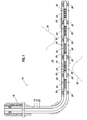
- FIG. 1 Representatively illustrated in FIG. 1 is a well system 10 which can embody principles of this disclosure.
- a wellbore 12 has a generally vertical uncased section 14 extending downwardly from casing 16, as well as a generally horizontal uncased section 18 extending through an earth formation 20.
- a tubular string 22 (such as a production tubing string) is installed in the wellbore 12. Interconnected in the tubular string 22 are multiple well screens 24, variable flow resistance systems 25 and packers 26.
- the packers 26 seal off an annulus 28 formed radially between the tubular string 22 and the wellbore section 18. In this manner, fluids 30 may be produced from multiple intervals or zones of the formation 20 via isolated portions of the annulus 28 between adjacent pairs of the packers 26.
- a well screen 24 and a variable flow resistance system 25 are interconnected in the tubular string 22.
- the well screen 24 filters the fluids 30 flowing into the tubular string 22 from the annulus 28.
- the variable flow resistance system 25 variably restricts flow of the fluids 30 into the tubular string 22, based on certain characteristics of the fluids.
- the wellbore 12 it is not necessary in keeping with the principles of this disclosure for the wellbore 12 to include a generally vertical wellbore section 14 or a generally horizontal wellbore section 18. It is not necessary for fluids 30 to be only produced from the formation 20 since, in other examples, fluids could be injected into a formation, fluids could be both injected into and produced from a formation, etc.
- variable flow resistance system 25 It is not necessary for one each of the well screen 24 and variable flow resistance system 25 to be positioned between each adjacent pair of the packers 26. It is not necessary for a single variable flow resistance system 25 to be used in conjunction with a single well screen 24. Any number, arrangement and/or combination of these components may be used.
- variable flow resistance system 25 it is not necessary for any variable flow resistance system 25 to be used with a well screen 24.
- the injected fluid could be flowed through a variable flow resistance system 25, without also flowing through a well screen 24.
- variable flow resistance systems 25, packers 26 or any other components of the tubular string 22 it is not necessary for the well screens 24, variable flow resistance systems 25, packers 26 or any other components of the tubular string 22 to be positioned in uncased sections 14, 18 of the wellbore 12. Any section of the wellbore 12 may be cased or uncased, and any portion of the tubular string 22 may be positioned in an uncased or cased section of the wellbore, in keeping with the principles of this disclosure.
- variable flow resistance systems 25 can provide these benefits by increasing resistance to flow if a fluid velocity increases beyond a selected level (e.g., to thereby balance flow among zones, prevent water or gas coning, etc.), and/or increasing resistance to flow if a fluid viscosity decreases below a selected level (e.g., to thereby restrict flow of an undesired fluid, such as water or gas, in an oil producing well).
- viscosity is used to indicate any of the rheological properties including kinematic viscosity, yield strength, viscoplasticity, surface tension, wettability, etc.
- Whether a fluid is a desired or an undesired fluid depends on the purpose of the production or injection operation being conducted. For example, if it is desired to produce oil from a well, but not to produce water or gas, then oil is a desired fluid and water and gas are undesired fluids. If it is desired to produce gas from a well, but not to produce water or oil, the gas is a desired fluid, and water and oil are undesired fluids. If it is desired to inject steam into a formation, but not to inject water, then steam is a desired fluid and water is an undesired fluid.
- a fluid composition 36 (which can include one or more fluids, such as oil and water, liquid water and steam, oil and gas, gas and water, oil, water and gas, etc.) flows into the well screen 24, is thereby filtered, and then flows into an inlet 38 of the variable flow resistance system 25.
- a fluid composition can include one or more undesired or desired fluids. Both steam and water can be combined in a fluid composition. As another example, oil, water and/or gas can be combined in a fluid composition.
- variable flow resistance system 25 Flow of the fluid composition 36 through the variable flow resistance system 25 is resisted based on one or more characteristics (such as viscosity, velocity, density, etc.) of the fluid composition.
- the fluid composition 36 is then discharged from the variable flow resistance system 25 to an interior of the tubular string 22 via an outlet 40.
- the well screen 24 may not be used in conjunction with the variable flow resistance system 25 (e.g., in injection operations), the fluid composition 36 could flow in an opposite direction through the various elements of the well system 10 (e.g., in injection operations), a single variable flow resistance system could be used in conjunction with multiple well screens, multiple variable flow resistance systems could be used with one or more well screens, the fluid composition could be received from or discharged into regions of a well other than an annulus or a tubular string, the fluid composition could flow through the variable flow resistance system prior to flowing through the well screen, any other components could be interconnected upstream or downstream of the well screen and/or variable flow resistance system, etc.
- the principles of this disclosure are not limited at all to the details of the example depicted in FIG. 2 and described herein.
- well screen 24 depicted in FIG. 2 is of the type known to those skilled in the art as a wire-wrapped well screen, any other types or combinations of well screens (such as sintered, expanded, pre-packed, wire mesh, etc.) may be used in other examples. Additional components (such as shrouds, shunt tubes, lines, instrumentation, sensors, inflow control devices, etc.) may also be used, if desired.
- variable flow resistance system 25 is depicted in simplified form in FIG. 2 , but in a preferred example the system can include various passages and devices for performing various functions, as described more fully below.
- the system 25 can at least partially extend circumferentially about the tubular string 22, or the system may be formed in a wall of a tubular structure interconnected as part of the tubular string.
- the system 25 may not extend circumferentially about a tubular string or be formed in a wall of a tubular structure.
- the system 25 could be formed in a flat structure, etc.
- the system 25 could be in a separate housing that is attached to the tubular string 22, or it could be oriented so that the axis of the outlet 40 is parallel to the axis of the tubular string.
- the system 25 could be on a logging string or attached to a device that is not tubular in shape. Any orientation or configuration of the system 25 may be used in keeping with the principles of this disclosure.
- FIGS. 3A & B a more detailed cross-sectional view of one example of the system 25 is representatively illustrated.
- the system 25 is depicted in FIGS. 3A & B as if it is "unrolled" from its circumferentially extending configuration to a generally planar configuration.
- the fluid composition 36 enters the system 25 via the inlet 38, and exits the system via the outlet 40.
- a resistance to flow of the fluid composition 36 through the system 25 varies based on one or more characteristics of the fluid composition.
- the inlet 38, the outlet 40, and a flow passage 42 and flow chamber 44 through which the fluid composition 36 flows between the inlet and the outlet, are elements of a vortex device 46 which restricts flow of the fluid composition based on certain characteristics of the fluid composition.
- Rotational flow of the fluid composition 36 increases in the chamber 44, thereby increasing restriction to flow through the chamber, for example, when a velocity of the fluid composition increases, when a viscosity of the fluid composition decreases, when a density of the fluid composition increases, and/or when a ratio of desired fluid to undesired fluid in the fluid composition decreases.
- the chamber 44 is generally cylindrical-shaped, and the flow passage 42 intersects the chamber tangentially, so that fluid entering the chamber via the inlet 48 tends to flow clockwise (as viewed in FIG. 3A ) about the outlet 40.
- a bypass passage 50 intersects the passage 42 downstream of the inlet 38, and the bypass passage also intersects the chamber 44 tangentially. However, fluid entering the chamber 44 through the bypass passage 50 via an inlet 52 tends to flow counterclockwise (as viewed in FIG. 3A ) about the outlet 40.
- a relatively high velocity and/or low viscosity fluid composition 36 flows through the flow passage 42 from the system inlet 38 to the flow chamber 44.
- a relatively low velocity and/or high viscosity fluid composition 36 flows through the flow passage 42 to the chamber 44 in FIG. 3B .
- a substantially larger proportion of the fluid composition flows to the chamber 44 via the bypass passage 50 in FIG. 3B .
- the flows entering the chamber 44 via the inlets 48, 52 are about equal. These flows effectively "cancel” or counteract each other, so that there is relatively little rotational flow of the fluid composition 36 in the chamber 44.
- the much more circuitous flow path taken by the fluid composition 36 in the example of FIG. 3A dissipates more of the fluid composition's energy at the same flow rate and, thus, results in more resistance to flow, as compared to the much more direct flow path taken by the fluid composition in the example of FIG. 3B .
- the variable flow resistance system 25 of FIGS. 3A & B will provide less resistance to flow of the fluid composition 36 when it has an increased ratio of desired to undesired fluid therein, and will provide greater resistance to flow when the fluid composition has a decreased ratio of desired to undesired fluid therein.
- the chamber 44 in this example has a cylindrical shape with a central outlet 40, and the fluid composition 36 (at least in FIG. 3A ) spirals about the chamber, increasing in velocity as it nears the outlet, driven by a pressure differential from the inlet 44 to the outlet, the chamber may be referred to as a "vortex" chamber.
- Circular flow inducing structures 54 are used in the chamber 44 in the configuration of FIGS. 3A & B .
- the structures 54 operate to maintain circular flow of the fluid composition 36 about the outlet 40, or at least to impede inward flow of the fluid composition toward the outlet, when the fluid composition does flow circularly about the outlet. Openings 56 in the structures 54 permit the fluid composition 36 to eventually flow inward to the outlet 40.
- the vortex device 46 is depicted in a situation in which an increased velocity and/or reduced viscosity of the fluid composition 36 results in a substantial proportion of the fluid composition flowing into the chamber 44 via the inlet 48.
- the fluid composition 36 thus, spirals about the outlet 40 in the chamber 44, and a resistance to flow through the vortex device 46 increases.
- a reduced viscosity can be due to a relatively low ratio of desired fluid to undesired fluid in the fluid composition 36.
- a velocity of the fluid composition 36 has decreased and/or a viscosity of the fluid composition has increased, and as a result, proportionately more of the fluid composition flows from the passage 42 and via the passage 50 to the inlet 52.
- the increased viscosity of the fluid composition 36 may be due to an increased ratio of desired to undesired fluids in the fluid composition.
- the flows into the chamber 44 from the two inlets 48, 52 are oppositely directed (or at least the flow of the fluid composition through the inlet 52 opposes the flow through the inlet 48), they counteract each other.
- the fluid composition 36 flows more directly to the outlet 40 and a resistance to flow through the vortex device 46 is decreased, and the fluid composition has reduced (or no) rotation at the outlet 40.
- FIG. 4 another configuration of the variable flow resistance system 25 is representatively illustrated.
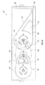
- the vortex device 46 is used in series with two additional vortex devices 58, 60.
- three vortex devices 46, 58, 60 are depicted in FIG. 4 , it will be appreciated that any number of vortex devices may be connected in series, in keeping with the principles of this disclosure.
- An outlet 62 of the vortex device 46 corresponds to an inlet of the vortex device 58
- an outlet 64 of the vortex device 58 corresponds to an inlet of the vortex device 60.
- the fluid composition 36 flows from the system 25 inlet 38 to the chamber 44, from the chamber 44 to the vortex device 58 via the outlet/inlet 62, from the outlet/inlet 62 to a vortex chamber 66 of the vortex device 58, from the chamber 66 to the vortex device 60 via the outlet/inlet 64, from the outlet/inlet 64 to a vortex chamber 68 of the vortex device 60, and from the chamber 68 to the outlet 40 of the system 25.
- Each of the vortex devices 58, 60 includes two passages 70, 72 and 74, 76, respectively, which function somewhat similar to the passages 42, 50 of the vortex device 46. However, the proportions of the fluid composition 36 which flows through each of the passages 70, 72 and 74, 76 varies based on a rotation of the fluid composition as it enters the respective vortex device 58, 60, as described more fully below.
- variable flow resistance system 25 a cross-sectional view of the variable flow resistance system 25 is representatively illustrated, as viewed along line 5-5 of FIG. 4 .
- the manner in which the outlet/inlet 62 and outlet/inlet 64 provide fluid communication between the vortex devices 46, 58, 60 can be readily seen.
- FIG. 5 it may also be seen that the vortex devices 46, 58, 60 are "stacked" in a compact manner, alternating orientation back and forth.
- the vortex devices 46, 58, 60 could be otherwise arranged, in keeping with the principles of this disclosure.
- variable flow resistance system 25 of FIGS. 4 & 5 is depicted, with a relatively low viscosity, high density and/or high velocity fluid composition 36 flowing through the system in FIG. 6A , and with a relatively high viscosity, low density and/or low velocity fluid composition flowing through the system in FIG. 6B .
- These examples demonstrate how the resistance to flow through the system 25 varies based on certain characteristics of the fluid composition 36.
- FIG. 6A significant spiraling flow of the fluid composition 36 is present in the vortex device 46 (similar to that described above in relation to FIG. 3A ). As a result, the fluid composition 36 is rotating significantly when it flows from the chamber 44 to the vortex device 58 via the outlet/inlet 62.
- This rotational flow of the fluid composition 36 causes a greater proportion of the fluid composition to flow through the passage 70, as compared to the proportion of the fluid composition which flows through the passage 72.
- the manner in which the rotating fluid composition 36 impinges on the curved walls of the passages 70, 72 at their intersection with the outlet/inlet 62 causes this difference in the proportions of the fluid composition which flows through each of the passages.
- the fluid composition 36 rotates as it exits the chamber 66 via the outlet/inlet 64.
- This rotational flow of the fluid composition 36 causes a greater proportion of the fluid composition to flow through the passage 74, as compared to the proportion of the fluid composition which flows through the passage 76.
- the manner in which the rotating fluid composition 36 impinges on the curved walls of the passages 74, 76 at their intersection with the outlet/inlet 64 causes this difference in the proportions of the fluid composition which flows through each of the passages.
- a relatively high viscosity and/or low velocity fluid composition 36 flows through the system 25.
- rotational flow of the fluid composition 36 in each of the chambers 44, 66, 68 is significantly reduced, and so the resistance to flow of the fluid composition through the chambers is also significantly reduced.
- the resistance to flow of the relatively high viscosity and/or low velocity fluid composition 36 is much less in FIG. 6B , as compared to the resistance to flow of the relatively low viscosity and/or high velocity fluid composition in FIG. 6A .
- any of the features of any of the configurations of the system 25 described above may be included in any of the other configurations of the system and, thus, it should be understood that these features are not exclusive to any one particular configuration of the system.
- the system 25 can be used in any type of well system (e.g., not only in the well system 10), and for accomplishing various purposes in various well operations, including but not limited to injection, stimulation, completion, production, conformance, drilling operations, etc.
- FIGS. 4-6B provides significant advancements to the art of controlling flow in a well.
- the resistance to flow of the fluid composition 36 through the system 25 can be substantially increased by connecting the vortex devices 46, 58, 60 in series, and by resisting flow of the fluid composition in response to its rotation as it passes from one vortex device to the next.
- the above disclosure provides to the art a variable flow resistance system 25 for use in a subterranean well.
- the system 25 can include a vortex device 58 or 60 through which a fluid composition 36 flows.
- a resistance to flow of the fluid composition 36 through the vortex device 58 or 60 is dependent on a rotation of the fluid composition 36 at an inlet 62 or 64 to the vortex device 58 or 60.
- the resistance to flow of the fluid composition 36 through the vortex device 58 or 60 can increase in response to an increased rotation of the fluid composition 36 at the inlet 62 or 64 to the vortex device 58 or 60.
- the rotation of the fluid composition 36 at the inlet 62 or 64 can increase in response to a decrease in viscosity of the fluid composition 36.
- the rotation of the fluid composition 36 at the inlet 62 or 64 can increase in response to an increase in velocity of the fluid composition 36.
- the rotation of the fluid composition 36 at the inlet 62 or 64 can increase in response to a decrease in a ratio of desired to undesired fluid in the fluid composition 36.
- An outlet 64 of the vortex device 58 can comprise an inlet 64 of another vortex device 60.
- the inlet 64 of the vortex device 60 can comprise an outlet 64 of another vortex device 58.
- the vortex device 58 can comprise at least first and second passages 70, 72 which receive the fluid composition 36 from an outlet 62 of another vortex device 46.
- a difference in proportions of the fluid composition 36 which flows through the respective first and second passages 70, 72 is dependent on the rotation of the fluid composition 36 at the outlet 62.
- the difference in the proportions of the fluid composition 36 which flows through the first and second passages 70, 72 may increase in response to an increase in velocity of the fluid composition 36.
- Rotation of the fluid composition 36 in a vortex chamber 66 increases in response to an increase in the difference in the proportions of the fluid composition 36 which flows through the first and second passages 70, 72.
- variable flow resistance system 25 which can include a first vortex 46 device having an outlet 62, and a second vortex device 58 which receives a fluid composition 36 from the outlet 62 of the first vortex device 46.
- a resistance to flow of the fluid composition 36 through the second vortex device 58 can be dependent on a rotation of the fluid composition 36 at the outlet 62 of the first vortex device 46.
- the rotation of the fluid composition 36 at the outlet 62 may increase in response to a decrease in viscosity of the fluid composition 36, in response to an increase in velocity of the fluid composition 36 and/or in response to a decrease in a ratio of desired to undesired fluid in the fluid composition 36.
- the resistance to flow of the fluid composition 36 through the second vortex device 58 can increase in response to an increase in the rotation of the fluid composition 36 at the outlet 62 of the first vortex device 46.
- An outlet 64 of the second vortex device 58 can comprise an inlet 64 of a third vortex device 60.
- the second vortex device 58 can include at least first and second passages 70, 72 which receive the fluid composition 36 from the outlet 62 of the first vortex device 46. A difference in proportions of the fluid composition 36 which flow through the respective first and second passages 70, 72 is dependent on the rotation of the fluid composition 36 at the outlet 62 of the first vortex device 46.
- the difference in the proportions of the fluid composition 36 which flows through the first and second passages 70, 72 may increase in response to an increase in velocity of the fluid composition 36.
- Rotation of the fluid composition 36 in a vortex chamber 66 of the second vortex device 58 may increase in response to an increase in the difference in the proportions of the fluid composition 36 which flows through the first and second passages 70, 72.
- variable flow resistance system 25 which can include a first vortex device 46 which causes increased rotation of a fluid composition 36 at an outlet 62 of the first vortex device 46 in response to an increase in a velocity of the fluid composition 36, and a second vortex device 58 which receives the fluid composition 36 from the outlet 62 of the first vortex device 46.
- a resistance to flow of the fluid composition 36 through the second vortex device 58 may be dependent on the rotation of the fluid composition 36 at the outlet 62 of the first vortex device 46.
- vortex devices 46, 58, 60 may be of the type known to those skilled in the art as fluid "diodes.”
- a well device for installation in a wellbore 12 in a subterranean zone (e.g., in formation 20) can include a first fluid diode (e.g., vortex device 46) comprising: a first interior surface 80 (see FIGS.
- a second fluid diode e.g., vortex device 58
- a second interior surface 82 that defines a second interior chamber 66 in fluid communication with the outlet 62, the second interior surface 82 operable to direct fluid (e.g., fluid composition 36) to rotate in the rotational direction in response to receiving the fluid rotating in the rotational direction through the outlet 62.
- the second fluid diode can include an inlet (in the FIGS. 4-6B example, the inlet of the chamber 58 is the same as the outlet 62 of the chamber 44) operable to receive the fluid 36 directly from the outlet 62.
- the second interior chamber 66 can comprise: a cylindroidal chamber 66, a first flow passage 70 from the inlet 62 to the cylindroidal chamber 66, and a second flow passage 72 from the inlet 62 to the cylindroidal chamber 66.
- the second interior surface 82 may be operable to direct a majority of the fluid 36 to the first flow passage 70 in response to receiving the fluid 36 rotating in the rotational direction through the inlet 62.
- the first interior surface 80 may be operable to direct fluid 36 to rotate in a rotational direction about a first axis of rotation 84
- the second interior surface 82 may be operable to direct fluid 36 to rotate in a rotational direction about a second axis of rotation 86.
- the first axis of rotation 84 can be parallel to the second axis of rotation 86.
- the first fluid diode 46 and the second fluid diode 58 may be in fluid communication between an interior and an exterior of the well device (e.g., the variable flow resistance system 25).
- the first fluid diode 46 and the second fluid diode 58 can be in fluid communication between the interior and the exterior to communicate production fluid 36 from the exterior of the well device 25 to the interior of the well device 25.
- the well device 25 may comprise a section of a completion string 22.
- the first and second fluid diodes 46, 58 can be in fluid communication between the interior and the exterior to communicate injection fluid 36 from the interior of the well device 25 to the exterior of the well device 25.
- the well device 25 may comprise a section of a working string 22.
- the outlet 62 can comprise a first outlet 62
- the first fluid diode 46 can further comprise a first inlet 38
- the first interior surface 80 may include a first side perimeter surface 80 and first opposing end surfaces 88, a greatest distance between the first opposing end surfaces 88 can be smaller than a largest dimension of the first opposing end surfaces 88, and the first side perimeter surface 80 may be operable to direct flow from the first inlet 38 to rotate about the first outlet 62.
- the second fluid diode 58 can comprise a second inlet 62 operable to receive the fluid 36 directly from the first outlet 62, the second interior surface 82 may include a second side perimeter surface 82 and second opposing end surfaces 90, a greatest distance between the second opposing end surfaces 90 may be smaller than a largest dimension of the second opposing end surfaces 90, and the second side perimeter surface 82 can be operable to direct flow from the second inlet 62 to rotate about a second outlet 64.
- a method of controlling flow in a wellbore 12 in a subterranean zone 20 can include communicating fluid 36 through a first fluid diode 46 and a second fluid diode 58 in a flow path between an interior and an exterior of a well device 25 in the subterranean zone 20. Communicating the fluid 36 through the first fluid diode 46 and the second fluid diode 58 can cause the fluid 36 to rotate within the first fluid diode 46 in a rotational direction and to rotate within the second fluid diode 58 in the rotational direction.
- the fluid 36 may comprise a production or injection fluid.
- Communicating the fluid 36 through the first fluid diode 46 and the second fluid diode 58 can control a resistance to a flow of the fluid 36 between the interior and the exterior based on a characteristic of the flow.
- the characteristic may comprise at least one of viscosity, velocity or density.
- a resistance to flow through the second fluid diode 58 can be based at least in part on a characteristic of inflow received by the second fluid diode 58 from the first fluid diode 46.
Landscapes
- Geology (AREA)
- Life Sciences & Earth Sciences (AREA)
- Engineering & Computer Science (AREA)
- Mining & Mineral Resources (AREA)
- Environmental & Geological Engineering (AREA)
- Fluid Mechanics (AREA)
- Physics & Mathematics (AREA)
- General Life Sciences & Earth Sciences (AREA)
- Geochemistry & Mineralogy (AREA)
- Footwear And Its Accessory, Manufacturing Method And Apparatuses (AREA)
- Cyclones (AREA)
- Jet Pumps And Other Pumps (AREA)
- Earth Drilling (AREA)
- Other Liquid Machine Or Engine Such As Wave Power Use (AREA)
Abstract
Description
- This application is a continuation-in-part of
US application serial no. 12/879846, filed 10 September 2010 - This disclosure relates generally to equipment utilized and operations performed in conjunction with a subterranean well and, in an example described below, more particularly provides a series configuration of variable flow restrictors.
- In a hydrocarbon production well, it is many times beneficial to be able to regulate flow of fluids from an earth formation into a wellbore. A variety of purposes may be served by such regulation, including prevention of water or gas coning, minimizing sand production, minimizing water and/or gas production, maximizing oil and/or gas production, balancing production among zones, etc.
- In an injection well, it is typically desirable to evenly inject water, steam, gas, etc., into multiple zones, so that hydrocarbons are displaced evenly through an earth formation, without the injected fluid prematurely breaking through to a production wellbore. Thus, the ability to regulate flow of fluids from a wellbore into an earth formation can also be beneficial for injection wells.
- Therefore, it will be appreciated that advancements in the art of controlling fluid flow in a well would be desirable in the circumstances mentioned above, and such advancements would also be beneficial in a wide variety of other circumstances.
- In the disclosure below, a variable flow resistance system is provided which brings improvements to the art of regulating fluid flow in wells. One example is described below in which resistance to flow through a vortex device is dependent on a rotation of a fluid composition as it enters the vortex device. Another example is described, in which multiple vortex devices are connected in series.
- In one aspect, the disclosure provides to the art a variable flow resistance system for use in a subterranean well. The system can include a vortex device through which a fluid composition flows. A resistance to flow of the fluid composition through the vortex device is dependent on a rotation of the fluid composition at an inlet to the vortex device.
- In another aspect, a variable flow resistance system described below can include a first vortex device having an outlet, and a second vortex device which receives a fluid composition from the outlet of the first vortex device. A resistance to flow of the fluid composition through the second vortex device is dependent on a rotation of the fluid composition at the outlet of the first vortex device.
- In yet another aspect, a variable flow resistance system can include a first vortex device which causes increased rotation of a fluid composition at an outlet of the first vortex device in response to an increase in a velocity of the fluid composition, and a second vortex device which receives the fluid composition from the outlet of the first vortex device. A resistance to flow of the fluid composition through the second vortex device is dependent on the rotation of the fluid composition at the outlet of the first vortex device.
- A well device for installation in a wellbore in a subterranean zone is also described below. In one example, the device includes a first fluid diode comprising a first interior surface that defines a first interior chamber, and an outlet from the first interior chamber, the first interior surface operable to direct fluid to rotate in a rotational direction through the outlet; and a second fluid diode comprising a second interior surface that defines a second interior chamber in fluid communication with the outlet, the second interior surface operable to direct fluid to rotate in the rotational direction in response to receiving the fluid rotating in the rotational direction through the outlet.
- The disclosure below also describes a method of controlling flow in a wellbore in a subterranean zone. An example is described in which the method comprises communicating fluid through a first fluid diode and a second fluid diode in a flow path between an interior and an exterior of a well device in the subterranean zone. Communicating the fluid through the first fluid diode and the second fluid diode can cause the fluid to rotate within the first fluid diode in a rotational direction and to rotate within the second fluid diode in the rotational direction.
- These and other features, advantages and benefits will become apparent to one of ordinary skill in the art upon careful consideration of the detailed description of representative examples below and the accompanying drawings, in which similar elements are indicated in the various figures using the same reference numbers.
-
-
FIG. 1 is a representative partially cross-sectional view of a well system which can embody principles of the present disclosure. -
FIG. 2 is an enlarged scale representative cross-sectional view of a well screen and a variable flow resistance system which may be used in the well system ofFIG. 1 . -
FIGS. 3A & B are representative "unrolled" cross-sectional views of one configuration of the variable flow resistance system, taken along line 3-3 ofFIG. 2 . -
FIG. 4 is a representative cross-sectional view of another configuration of the variable flow resistance system. -
FIG. 5 is a representative cross-sectional of the variable flow resistance system ofFIG. 4 , taken along line 5-5. -
FIGS. 6A & B are representative cross-sectional views the variable flow resistance system ofFIG. 4 , depicting changes in flow resistance resulting from changes in characteristics of a fluid composition. - Representatively illustrated in
FIG. 1 is awell system 10 which can embody principles of this disclosure. As depicted inFIG. 1 , awellbore 12 has a generally verticaluncased section 14 extending downwardly fromcasing 16, as well as a generally horizontaluncased section 18 extending through anearth formation 20. - A tubular string 22 (such as a production tubing string) is installed in the
wellbore 12. Interconnected in thetubular string 22 aremultiple well screens 24, variableflow resistance systems 25 andpackers 26. - The
packers 26 seal off anannulus 28 formed radially between thetubular string 22 and thewellbore section 18. In this manner,fluids 30 may be produced from multiple intervals or zones of theformation 20 via isolated portions of theannulus 28 between adjacent pairs of thepackers 26. - Positioned between each adjacent pair of the
packers 26, a wellscreen 24 and a variableflow resistance system 25 are interconnected in thetubular string 22. The wellscreen 24 filters thefluids 30 flowing into thetubular string 22 from theannulus 28. The variableflow resistance system 25 variably restricts flow of thefluids 30 into thetubular string 22, based on certain characteristics of the fluids. - At this point, it should be noted that the
well system 10 is illustrated in the drawings and is described herein as merely one example of a wide variety of well systems in which the principles of this disclosure can be utilized. It should be clearly understood that the principles of this disclosure are not limited at all to any of the details of thewell system 10, or components thereof, depicted in the drawings or described herein. - For example, it is not necessary in keeping with the principles of this disclosure for the
wellbore 12 to include a generallyvertical wellbore section 14 or a generallyhorizontal wellbore section 18. It is not necessary forfluids 30 to be only produced from theformation 20 since, in other examples, fluids could be injected into a formation, fluids could be both injected into and produced from a formation, etc. - It is not necessary for one each of the well
screen 24 and variableflow resistance system 25 to be positioned between each adjacent pair of thepackers 26. It is not necessary for a single variableflow resistance system 25 to be used in conjunction with asingle well screen 24. Any number, arrangement and/or combination of these components may be used. - It is not necessary for any variable
flow resistance system 25 to be used with a wellscreen 24. For example, in injection operations, the injected fluid could be flowed through a variableflow resistance system 25, without also flowing through a wellscreen 24. - It is not necessary for the
well screens 24, variableflow resistance systems 25,packers 26 or any other components of thetubular string 22 to be positioned inuncased sections wellbore 12. Any section of thewellbore 12 may be cased or uncased, and any portion of thetubular string 22 may be positioned in an uncased or cased section of the wellbore, in keeping with the principles of this disclosure. - It should be clearly understood, therefore, that this disclosure describes how to make and use certain examples, but the principles of the disclosure are not limited to any details of those examples. Instead, those principles can be applied to a variety of other examples using the knowledge obtained from this disclosure.
- It will be appreciated by those skilled in the art that it would be beneficial to be able to regulate flow of the
fluids 30 into thetubular string 22 from each zone of theformation 20, for example, to prevent water coning 32 or gas coning 34 in the formation. Other uses for flow regulation in a well include, but are not limited to, balancing production from (or injection into) multiple zones, minimizing production or injection of undesired fluids, maximizing production or injection of desired fluids, etc. - Examples of the variable
flow resistance systems 25 described more fully below can provide these benefits by increasing resistance to flow if a fluid velocity increases beyond a selected level (e.g., to thereby balance flow among zones, prevent water or gas coning, etc.), and/or increasing resistance to flow if a fluid viscosity decreases below a selected level (e.g., to thereby restrict flow of an undesired fluid, such as water or gas, in an oil producing well). - As used herein, the term "viscosity" is used to indicate any of the rheological properties including kinematic viscosity, yield strength, viscoplasticity, surface tension, wettability, etc.
- Whether a fluid is a desired or an undesired fluid depends on the purpose of the production or injection operation being conducted. For example, if it is desired to produce oil from a well, but not to produce water or gas, then oil is a desired fluid and water and gas are undesired fluids. If it is desired to produce gas from a well, but not to produce water or oil, the gas is a desired fluid, and water and oil are undesired fluids. If it is desired to inject steam into a formation, but not to inject water, then steam is a desired fluid and water is an undesired fluid.
- If gas is being flowed, it can be difficult to restrict flow of the gas using conventional techniques, which typically involve interposing small diameter passages, orifices, etc. in the gas flow. Unfortunately, these devices can have an increased volumetric flow rate when gas is flowing instead of oil or another fluid, and can result in erosion problems.
- Note that, at downhole temperatures and pressures, hydrocarbon gas can actually be completely or partially in liquid phase. Thus, it should be understood that when the term "gas" is used herein, supercritical, liquid, condensate and/or gaseous phases are included within the scope of that term.
- Referring additionally now to
FIG. 2 , an enlarged scale cross-sectional view of one of the variableflow resistance systems 25 and a portion of one of the well screens 24 is representatively illustrated. In this example, a fluid composition 36 (which can include one or more fluids, such as oil and water, liquid water and steam, oil and gas, gas and water, oil, water and gas, etc.) flows into thewell screen 24, is thereby filtered, and then flows into aninlet 38 of the variableflow resistance system 25. - A fluid composition can include one or more undesired or desired fluids. Both steam and water can be combined in a fluid composition. As another example, oil, water and/or gas can be combined in a fluid composition.
- Flow of the
fluid composition 36 through the variableflow resistance system 25 is resisted based on one or more characteristics (such as viscosity, velocity, density, etc.) of the fluid composition. Thefluid composition 36 is then discharged from the variableflow resistance system 25 to an interior of thetubular string 22 via anoutlet 40. - In other examples, the
well screen 24 may not be used in conjunction with the variable flow resistance system 25 (e.g., in injection operations), thefluid composition 36 could flow in an opposite direction through the various elements of the well system 10 (e.g., in injection operations), a single variable flow resistance system could be used in conjunction with multiple well screens, multiple variable flow resistance systems could be used with one or more well screens, the fluid composition could be received from or discharged into regions of a well other than an annulus or a tubular string, the fluid composition could flow through the variable flow resistance system prior to flowing through the well screen, any other components could be interconnected upstream or downstream of the well screen and/or variable flow resistance system, etc. Thus, it will be appreciated that the principles of this disclosure are not limited at all to the details of the example depicted inFIG. 2 and described herein. - Although the
well screen 24 depicted inFIG. 2 is of the type known to those skilled in the art as a wire-wrapped well screen, any other types or combinations of well screens (such as sintered, expanded, pre-packed, wire mesh, etc.) may be used in other examples. Additional components (such as shrouds, shunt tubes, lines, instrumentation, sensors, inflow control devices, etc.) may also be used, if desired. - The variable
flow resistance system 25 is depicted in simplified form inFIG. 2 , but in a preferred example the system can include various passages and devices for performing various functions, as described more fully below. In addition, thesystem 25 can at least partially extend circumferentially about thetubular string 22, or the system may be formed in a wall of a tubular structure interconnected as part of the tubular string. - In other examples, the
system 25 may not extend circumferentially about a tubular string or be formed in a wall of a tubular structure. For example, thesystem 25 could be formed in a flat structure, etc. Thesystem 25 could be in a separate housing that is attached to thetubular string 22, or it could be oriented so that the axis of theoutlet 40 is parallel to the axis of the tubular string. Thesystem 25 could be on a logging string or attached to a device that is not tubular in shape. Any orientation or configuration of thesystem 25 may be used in keeping with the principles of this disclosure. - Referring additionally now to
FIGS. 3A & B , a more detailed cross-sectional view of one example of thesystem 25 is representatively illustrated. Thesystem 25 is depicted inFIGS. 3A & B as if it is "unrolled" from its circumferentially extending configuration to a generally planar configuration. - As described above, the
fluid composition 36 enters thesystem 25 via theinlet 38, and exits the system via theoutlet 40. A resistance to flow of thefluid composition 36 through thesystem 25 varies based on one or more characteristics of the fluid composition. - The
inlet 38, theoutlet 40, and aflow passage 42 and flowchamber 44 through which thefluid composition 36 flows between the inlet and the outlet, are elements of avortex device 46 which restricts flow of the fluid composition based on certain characteristics of the fluid composition. Rotational flow of thefluid composition 36 increases in thechamber 44, thereby increasing restriction to flow through the chamber, for example, when a velocity of the fluid composition increases, when a viscosity of the fluid composition decreases, when a density of the fluid composition increases, and/or when a ratio of desired fluid to undesired fluid in the fluid composition decreases. - As depicted in
FIG. 3A , thechamber 44 is generally cylindrical-shaped, and theflow passage 42 intersects the chamber tangentially, so that fluid entering the chamber via theinlet 48 tends to flow clockwise (as viewed inFIG. 3A ) about theoutlet 40. Abypass passage 50 intersects thepassage 42 downstream of theinlet 38, and the bypass passage also intersects thechamber 44 tangentially. However, fluid entering thechamber 44 through thebypass passage 50 via aninlet 52 tends to flow counterclockwise (as viewed inFIG. 3A ) about theoutlet 40. - In
FIG. 3A , a relatively high velocity and/or lowviscosity fluid composition 36 flows through theflow passage 42 from thesystem inlet 38 to theflow chamber 44. In contrast, a relatively low velocity and/or highviscosity fluid composition 36 flows through theflow passage 42 to thechamber 44 inFIG. 3B . - Only a small proportion of the
fluid composition 36 flows to thechamber 44 via thebypass passage 50 inFIG. 3A . Thus, a substantial proportion of thefluid composition 36 rotates in thechamber 44, spiraling with increasing rotational velocity toward theoutlet 40. Note that the rotation of thefluid composition 36 at theoutlet 40 will increase as the velocity of the fluid composition entering theinlet 38 increases, and as a viscosity of the fluid composition decreases. - A substantially larger proportion of the fluid composition flows to the
chamber 44 via thebypass passage 50 inFIG. 3B . In this example, the flows entering thechamber 44 via theinlets fluid composition 36 in thechamber 44. - It will be appreciated that the much more circuitous flow path taken by the
fluid composition 36 in the example ofFIG. 3A dissipates more of the fluid composition's energy at the same flow rate and, thus, results in more resistance to flow, as compared to the much more direct flow path taken by the fluid composition in the example ofFIG. 3B . If oil is a desired fluid, and water and/or gas are undesired fluids, then it will be appreciated that the variableflow resistance system 25 ofFIGS. 3A & B will provide less resistance to flow of thefluid composition 36 when it has an increased ratio of desired to undesired fluid therein, and will provide greater resistance to flow when the fluid composition has a decreased ratio of desired to undesired fluid therein. - Since the
chamber 44 in this example has a cylindrical shape with acentral outlet 40, and the fluid composition 36 (at least inFIG. 3A ) spirals about the chamber, increasing in velocity as it nears the outlet, driven by a pressure differential from theinlet 44 to the outlet, the chamber may be referred to as a "vortex" chamber. - Circular
flow inducing structures 54 are used in thechamber 44 in the configuration ofFIGS. 3A & B . Thestructures 54 operate to maintain circular flow of thefluid composition 36 about theoutlet 40, or at least to impede inward flow of the fluid composition toward the outlet, when the fluid composition does flow circularly about the outlet.Openings 56 in thestructures 54 permit thefluid composition 36 to eventually flow inward to theoutlet 40. - As discussed above, in
FIG. 3A , thevortex device 46 is depicted in a situation in which an increased velocity and/or reduced viscosity of thefluid composition 36 results in a substantial proportion of the fluid composition flowing into thechamber 44 via theinlet 48. Thefluid composition 36, thus, spirals about theoutlet 40 in thechamber 44, and a resistance to flow through thevortex device 46 increases. A reduced viscosity can be due to a relatively low ratio of desired fluid to undesired fluid in thefluid composition 36. - Relatively little of the
fluid composition 36 flows into thechamber 44 via theinlet 52 inFIG. 3A , because theflow passage 50 is branched from theflow passage 42 in a manner such that most of the fluid composition remains in theflow passage 42. At relatively high velocities, high densities and/or low viscosities, thefluid composition 36 tends to flow past theflow passage 50. - In
FIG. 3B , a velocity of thefluid composition 36 has decreased and/or a viscosity of the fluid composition has increased, and as a result, proportionately more of the fluid composition flows from thepassage 42 and via thepassage 50 to theinlet 52. The increased viscosity of thefluid composition 36 may be due to an increased ratio of desired to undesired fluids in the fluid composition. - Since, in
FIG. 3B , the flows into thechamber 44 from the twoinlets inlet 52 opposes the flow through the inlet 48), they counteract each other. Thus, thefluid composition 36 flows more directly to theoutlet 40 and a resistance to flow through thevortex device 46 is decreased, and the fluid composition has reduced (or no) rotation at theoutlet 40. - Referring additionally now to
FIG. 4 , another configuration of the variableflow resistance system 25 is representatively illustrated. In this configuration, thevortex device 46 is used in series with twoadditional vortex devices vortex devices FIG. 4 , it will be appreciated that any number of vortex devices may be connected in series, in keeping with the principles of this disclosure. - An
outlet 62 of thevortex device 46 corresponds to an inlet of thevortex device 58, and anoutlet 64 of thevortex device 58 corresponds to an inlet of thevortex device 60. Thefluid composition 36 flows from thesystem 25inlet 38 to thechamber 44, from thechamber 44 to thevortex device 58 via the outlet/inlet 62, from the outlet/inlet 62 to avortex chamber 66 of thevortex device 58, from thechamber 66 to thevortex device 60 via the outlet/inlet 64, from the outlet/inlet 64 to avortex chamber 68 of thevortex device 60, and from thechamber 68 to theoutlet 40 of thesystem 25. - Each of the
vortex devices passages passages vortex device 46. However, the proportions of thefluid composition 36 which flows through each of thepassages respective vortex device - Referring additionally now to
FIG. 5 , a cross-sectional view of the variableflow resistance system 25 is representatively illustrated, as viewed along line 5-5 ofFIG. 4 . In this view, the manner in which the outlet/inlet 62 and outlet/inlet 64 provide fluid communication between thevortex devices - In
FIG. 5 , it may also be seen that thevortex devices vortex devices - Referring additionally now to
FIGS. 6A & B , the variableflow resistance system 25 ofFIGS. 4 &5 is depicted, with a relatively low viscosity, high density and/or highvelocity fluid composition 36 flowing through the system inFIG. 6A , and with a relatively high viscosity, low density and/or low velocity fluid composition flowing through the system inFIG. 6B . These examples demonstrate how the resistance to flow through thesystem 25 varies based on certain characteristics of thefluid composition 36. - In
FIG. 6A , significant spiraling flow of thefluid composition 36 is present in the vortex device 46 (similar to that described above in relation toFIG. 3A ). As a result, thefluid composition 36 is rotating significantly when it flows from thechamber 44 to thevortex device 58 via the outlet/inlet 62. - This rotational flow of the
fluid composition 36 causes a greater proportion of the fluid composition to flow through thepassage 70, as compared to the proportion of the fluid composition which flows through thepassage 72. The manner in which the rotatingfluid composition 36 impinges on the curved walls of thepassages inlet 62 causes this difference in the proportions of the fluid composition which flows through each of the passages. - Since a greater proportion of the
fluid composition 36 flows into thechamber 66 of thevortex device 58 via thepassage 70, the fluid composition rotates within thechamber 66, similar to the manner in which the fluid composition flows spirally through thechamber 44 of thevortex device 46. This spiraling flow of thefluid composition 36 through thechamber 66 generates resistance to flow, with the resistance to flow increasing with increased rotational flow of the fluid composition in the chamber. - The
fluid composition 36 rotates as it exits thechamber 66 via the outlet/inlet 64. This rotational flow of thefluid composition 36 causes a greater proportion of the fluid composition to flow through thepassage 74, as compared to the proportion of the fluid composition which flows through thepassage 76. Similar to that described above for thevortex chamber 58, the manner in which the rotatingfluid composition 36 impinges on the curved walls of thepassages inlet 64 causes this difference in the proportions of the fluid composition which flows through each of the passages. - Since a greater proportion of the
fluid composition 36 flows into thechamber 68 of thevortex device 60 via thepassage 74, the fluid composition rotates within thechamber 68, similar to the manner in which the fluid composition flows spirally through thechamber 66 of thevortex device 58. This spiraling flow of thefluid composition 36 through thechamber 68 generates resistance to flow, with the resistance to flow increasing with increased rotational flow of the fluid composition in the chamber. - Thus, with the relatively high velocity and/or low
viscosity fluid composition 36 inFIG. 6A , rotational flow and resistance to flow is increased in each of thevortex devices single vortex device 46. In addition, the rotational flow through thechambers vortex devices fluid composition 36 at each of the outlet/inlets - In
FIG. 6B , a relatively high viscosity and/or lowvelocity fluid composition 36 flows through thesystem 25. Note that rotational flow of thefluid composition 36 in each of thechambers velocity fluid composition 36 is much less inFIG. 6B , as compared to the resistance to flow of the relatively low viscosity and/or high velocity fluid composition inFIG. 6A . - Note that any of the features of any of the configurations of the
system 25 described above may be included in any of the other configurations of the system and, thus, it should be understood that these features are not exclusive to any one particular configuration of the system. Thesystem 25 can be used in any type of well system (e.g., not only in the well system 10), and for accomplishing various purposes in various well operations, including but not limited to injection, stimulation, completion, production, conformance, drilling operations, etc. - It will be appreciated that the
system 25 ofFIGS. 4-6B provides significant advancements to the art of controlling flow in a well. The resistance to flow of thefluid composition 36 through thesystem 25 can be substantially increased by connecting thevortex devices - The above disclosure provides to the art a variable
flow resistance system 25 for use in a subterranean well. Thesystem 25 can include avortex device fluid composition 36 flows. A resistance to flow of thefluid composition 36 through thevortex device fluid composition 36 at aninlet vortex device - The resistance to flow of the
fluid composition 36 through thevortex device fluid composition 36 at theinlet vortex device - The rotation of the
fluid composition 36 at theinlet fluid composition 36. - The rotation of the
fluid composition 36 at theinlet fluid composition 36. - The rotation of the
fluid composition 36 at theinlet fluid composition 36. - An
outlet 64 of thevortex device 58 can comprise aninlet 64 of anothervortex device 60. Theinlet 64 of thevortex device 60 can comprise anoutlet 64 of anothervortex device 58. - The
vortex device 58 can comprise at least first andsecond passages fluid composition 36 from anoutlet 62 of anothervortex device 46. A difference in proportions of thefluid composition 36 which flows through the respective first andsecond passages fluid composition 36 at theoutlet 62. The difference in the proportions of thefluid composition 36 which flows through the first andsecond passages fluid composition 36. - Rotation of the
fluid composition 36 in avortex chamber 66 increases in response to an increase in the difference in the proportions of thefluid composition 36 which flows through the first andsecond passages - The above disclosure also describes a variable
flow resistance system 25 which can include afirst vortex 46 device having anoutlet 62, and asecond vortex device 58 which receives afluid composition 36 from theoutlet 62 of thefirst vortex device 46. A resistance to flow of thefluid composition 36 through thesecond vortex device 58 can be dependent on a rotation of thefluid composition 36 at theoutlet 62 of thefirst vortex device 46. - The rotation of the
fluid composition 36 at theoutlet 62 may increase in response to a decrease in viscosity of thefluid composition 36, in response to an increase in velocity of thefluid composition 36 and/or in response to a decrease in a ratio of desired to undesired fluid in thefluid composition 36. - The resistance to flow of the
fluid composition 36 through thesecond vortex device 58 can increase in response to an increase in the rotation of thefluid composition 36 at theoutlet 62 of thefirst vortex device 46. - An
outlet 64 of thesecond vortex device 58 can comprise aninlet 64 of athird vortex device 60. - The
second vortex device 58 can include at least first andsecond passages fluid composition 36 from theoutlet 62 of thefirst vortex device 46. A difference in proportions of thefluid composition 36 which flow through the respective first andsecond passages fluid composition 36 at theoutlet 62 of thefirst vortex device 46. - The difference in the proportions of the
fluid composition 36 which flows through the first andsecond passages fluid composition 36. - Rotation of the
fluid composition 36 in avortex chamber 66 of thesecond vortex device 58 may increase in response to an increase in the difference in the proportions of thefluid composition 36 which flows through the first andsecond passages - The above disclosure also describes a variable
flow resistance system 25 which can include afirst vortex device 46 which causes increased rotation of afluid composition 36 at anoutlet 62 of thefirst vortex device 46 in response to an increase in a velocity of thefluid composition 36, and asecond vortex device 58 which receives thefluid composition 36 from theoutlet 62 of thefirst vortex device 46. A resistance to flow of thefluid composition 36 through thesecond vortex device 58 may be dependent on the rotation of thefluid composition 36 at theoutlet 62 of thefirst vortex device 46. - Note that the
vortex devices - A well device (e.g., the variable flow resistance system 25) for installation in a
wellbore 12 in a subterranean zone (e.g., in formation 20) can include a first fluid diode (e.g., vortex device 46) comprising: a first interior surface 80 (seeFIGS. 4 &5 ) that defines a firstinterior chamber 44, and anoutlet 62 from the firstinterior chamber 44, the firstinterior surface 80 operable to direct fluid (e.g., fluid composition 36) to rotate in a rotational direction through theoutlet 62; and a second fluid diode (e.g., vortex device 58) comprising: a secondinterior surface 82 that defines a secondinterior chamber 66 in fluid communication with theoutlet 62, the secondinterior surface 82 operable to direct fluid (e.g., fluid composition 36) to rotate in the rotational direction in response to receiving the fluid rotating in the rotational direction through theoutlet 62. - The second fluid diode can include an inlet (in the
FIGS. 4-6B example, the inlet of thechamber 58 is the same as theoutlet 62 of the chamber 44) operable to receive the fluid 36 directly from theoutlet 62. The secondinterior chamber 66 can comprise: acylindroidal chamber 66, afirst flow passage 70 from theinlet 62 to thecylindroidal chamber 66, and asecond flow passage 72 from theinlet 62 to thecylindroidal chamber 66. - The second
interior surface 82 may be operable to direct a majority of the fluid 36 to thefirst flow passage 70 in response to receiving the fluid 36 rotating in the rotational direction through theinlet 62. - The first
interior surface 80 may be operable todirect fluid 36 to rotate in a rotational direction about a first axis ofrotation 84, and the secondinterior surface 82 may be operable todirect fluid 36 to rotate in a rotational direction about a second axis ofrotation 86. The first axis ofrotation 84 can be parallel to the second axis ofrotation 86. - The
first fluid diode 46 and thesecond fluid diode 58 may be in fluid communication between an interior and an exterior of the well device (e.g., the variable flow resistance system 25). Thefirst fluid diode 46 and thesecond fluid diode 58 can be in fluid communication between the interior and the exterior to communicateproduction fluid 36 from the exterior of thewell device 25 to the interior of thewell device 25. Thewell device 25 may comprise a section of acompletion string 22. - The first and second
fluid diodes injection fluid 36 from the interior of thewell device 25 to the exterior of thewell device 25. Thewell device 25 may comprise a section of a workingstring 22. - The
outlet 62 can comprise afirst outlet 62, thefirst fluid diode 46 can further comprise afirst inlet 38, the firstinterior surface 80 may include a firstside perimeter surface 80 and first opposing end surfaces 88, a greatest distance between the first opposing end surfaces 88 can be smaller than a largest dimension of the first opposing end surfaces 88, and the firstside perimeter surface 80 may be operable to direct flow from thefirst inlet 38 to rotate about thefirst outlet 62. - The
second fluid diode 58 can comprise asecond inlet 62 operable to receive the fluid 36 directly from thefirst outlet 62, the secondinterior surface 82 may include a secondside perimeter surface 82 and second opposing end surfaces 90, a greatest distance between the second opposing end surfaces 90 may be smaller than a largest dimension of the second opposing end surfaces 90, and the secondside perimeter surface 82 can be operable to direct flow from thesecond inlet 62 to rotate about asecond outlet 64. - A method of controlling flow in a
wellbore 12 in asubterranean zone 20 can include communicatingfluid 36 through a firstfluid diode 46 and asecond fluid diode 58 in a flow path between an interior and an exterior of awell device 25 in thesubterranean zone 20. Communicating the fluid 36 through thefirst fluid diode 46 and thesecond fluid diode 58 can cause the fluid 36 to rotate within thefirst fluid diode 46 in a rotational direction and to rotate within thesecond fluid diode 58 in the rotational direction. - The fluid 36 may comprise a production or injection fluid.
- Communicating the fluid 36 through the
first fluid diode 46 and thesecond fluid diode 58 can control a resistance to a flow of the fluid 36 between the interior and the exterior based on a characteristic of the flow. The characteristic may comprise at least one of viscosity, velocity or density. - A resistance to flow through the
second fluid diode 58 can be based at least in part on a characteristic of inflow received by thesecond fluid diode 58 from thefirst fluid diode 46. - It is to be understood that the various examples described above may be utilized in various orientations, such as inclined, inverted, horizontal, vertical, etc., and in various configurations, without departing from the principles of the present disclosure. The embodiments illustrated in the drawings are depicted and described merely as examples of useful applications of the principles of the disclosure, which are not limited to any specific details of these embodiments.
- Of course, a person skilled in the art would, upon a careful consideration of the above description of representative embodiments, readily appreciate that many modifications, additions, substitutions, deletions, and other changes may be made to these specific embodiments, and such changes are within the scope of the principles of the present disclosure. Accordingly, the foregoing detailed description is to be clearly understood as being given by way of illustration and example only, the spirit and scope of the present invention being limited solely by the appended claims and their equivalents.
Claims (15)
- A well device for installation in a wellbore in a subterranean zone, comprising:a first fluid diode comprising:a first interior surface that defines a first interior chamber, andan outlet from the first interior chamber, the first interior surface operable to direct fluid to rotate in a rotational direction through the outlet; anda second fluid diode comprising:a second interior surface that defines a second interior chamber in fluid communication with the outlet, the second interior surface operable to direct fluid to rotate in the rotational direction in response to receiving the fluid rotating in the rotational direction through the outlet.
- The well device of claim 1, wherein the second fluid diode includes an inlet operable to receive the fluid directly from the outlet, and the second interior chamber comprises:a cylindroidal chamber;a first flow passage from the inlet to the cylindroidal chamber; anda second flow passage from the inlet to the cylindroidal chamber.
- The well device of claim 2, wherein the second interior surface is operable to direct a majority of the fluid to the first flow passage in response to receiving the fluid rotating in the rotational direction through the inlet.
- The well device of claim 1, wherein the first interior surface is operable to direct fluid to rotate in the rotational direction about a first axis of rotation, and the second interior surface is operable to direct fluid to rotate in the rotational direction about a second axis of rotation, which is preferably parallel to the first axis of rotation.
- The well device of claim 1, wherein the first fluid diode and the second fluid diode are in fluid communication between the interior and the exterior to communicate production fluid from the exterior of the well device to the interior of the well device.
- The well device of claim 5, wherein the well device comprises a section of a completion string.
- The well device of claim 1, wherein the first and second fluid diodes are in fluid communication between the interior and the exterior to communicate injection fluid from the interior of the well device to the exterior of the well device.
- The well device of claim 4, wherein the well device comprises a section of a working string.
- The well device of claim 1, wherein the outlet comprises a first outlet, the first fluid diode further comprises a first inlet, the first interior surface includes a first side perimeter surface and first opposing end surfaces, a greatest distance between the first opposing end surfaces is smaller than a largest dimension of the first opposing end surfaces, and the first side perimeter surface is operable to direct flow from the first inlet to rotate about the first outlet.
- The well device of claim 9, wherein the second fluid diode further comprises a second inlet operable to receive the fluid directly from the first outlet, the second interior surface includes a second side perimeter surface and second opposing end surfaces, a greatest distance between the second opposing end surfaces is smaller than a largest dimension of the second opposing end surfaces, and the second side perimeter surface is operable to direct flow from the second inlet to rotate about a second outlet.
- A method of controlling flow in a wellbore in a subterranean zone, comprising:communicating fluid through a first fluid diode and a second fluid diode in a flow path between an interior and an exterior of a well device in the subterranean zone, communicating the fluid through the first fluid diode and the second fluid diode causes the fluid to rotate within the first fluid diode in a rotational direction and to rotate within the second fluid diode in the rotational direction.
- The method of claim 11, wherein the fluid comprises a production fluid or an injection fluid.
- The method of claim 11, wherein communicating the fluid through the first fluid diode and the second fluid diode controls a resistance to a flow of the fluid between the interior and the exterior based on a characteristic of the flow.
- The method of claim 13, wherein the characteristic comprises at least one of viscosity, velocity and density.
- The method of claim 13, wherein a resistance to flow through the second fluid diode is based at least in part on a characteristic of inflow received by the second fluid diode from the first fluid diode.
Applications Claiming Priority (1)
| Application Number | Priority Date | Filing Date | Title |
|---|---|---|---|
| US13/359,617 US8950502B2 (en) | 2010-09-10 | 2012-01-27 | Series configured variable flow restrictors for use in a subterranean well |
Publications (2)
| Publication Number | Publication Date |
|---|---|
| EP2620587A2 true EP2620587A2 (en) | 2013-07-31 |
| EP2620587A3 EP2620587A3 (en) | 2015-10-21 |
Family
ID=47713858
Family Applications (1)
| Application Number | Title | Priority Date | Filing Date |
|---|---|---|---|
| EP13152471.2A Withdrawn EP2620587A3 (en) | 2012-01-27 | 2013-01-24 | Series configured variable flow restrictors for use in a subterranean well |
Country Status (10)
| Country | Link |
|---|---|
| EP (1) | EP2620587A3 (en) |
| CN (1) | CN103225494B (en) |
| AU (1) | AU2013200245B2 (en) |
| BR (1) | BR102013001846A2 (en) |
| CA (1) | CA2803212C (en) |
| CO (1) | CO7010167A1 (en) |
| MX (1) | MX2013001009A (en) |
| MY (1) | MY167298A (en) |
| RU (1) | RU2532485C2 (en) |
| SG (1) | SG192387A1 (en) |
Cited By (4)
| Publication number | Priority date | Publication date | Assignee | Title |
|---|---|---|---|---|
| US11261698B2 (en) | 2017-08-03 | 2022-03-01 | Halliburton Energy Services, Inc. | Autonomous inflow control device with a wettability operable fluid selector |
| US20230193723A1 (en) * | 2021-12-16 | 2023-06-22 | Floway Innovations Inc. | Autonomous Flow Control Devices for Viscosity Dominant Flow |
| WO2025053839A1 (en) * | 2023-09-05 | 2025-03-13 | Halliburton Energy Services, Inc. | Fluid flow control system employing a fluidic diode for control pressure |
| WO2025053840A1 (en) * | 2023-09-05 | 2025-03-13 | Halliburton Energy Services, Inc. | Fluid flow control system employing a flow restrictor for control pressure |
Families Citing this family (2)
| Publication number | Priority date | Publication date | Assignee | Title |
|---|---|---|---|---|
| CN108240206A (en) * | 2018-01-08 | 2018-07-03 | 北京合力奇点科技有限公司 | Switchable tune flow control water installations and its control water completion flow string |
| CN115707857A (en) * | 2021-08-19 | 2023-02-21 | 中国石油化工股份有限公司 | Well completion and production integrated pipe column |
Family Cites Families (14)
| Publication number | Priority date | Publication date | Assignee | Title |
|---|---|---|---|---|
| JPS4815551B1 (en) * | 1969-01-28 | 1973-05-15 | ||
| US3586104A (en) * | 1969-12-01 | 1971-06-22 | Halliburton Co | Fluidic vortex choke |
| SU1183770A1 (en) * | 1983-07-11 | 1985-10-07 | Донецкий Ордена Трудового Красного Знамени Политехнический Институт | Arrangement for damping water hammer |
| DE3615747A1 (en) * | 1986-05-09 | 1987-11-12 | Bielefeldt Ernst August | METHOD FOR SEPARATING AND / OR SEPARATING SOLID AND / OR LIQUID PARTICLES WITH A SPIRAL CHAMBER SEPARATOR WITH A SUBMERSIBLE TUBE AND SPIRAL CHAMBER SEPARATOR FOR CARRYING OUT THE METHOD |
| GB0312331D0 (en) * | 2003-05-30 | 2003-07-02 | Imi Vision Ltd | Improvements in fluid control |
| CN101326340B (en) * | 2005-12-19 | 2012-10-31 | 埃克森美孚上游研究公司 | System and method for hydrocarbon production |
| US7708068B2 (en) * | 2006-04-20 | 2010-05-04 | Halliburton Energy Services, Inc. | Gravel packing screen with inflow control device and bypass |
| BRPI0714025B1 (en) * | 2006-07-07 | 2017-12-05 | Statoil Petroleum As | METHOD FOR AUTOMATICALLY ADJUSTING THE FLOW OF A FLUID THROUGH VALVE OR FLOW CONTROL DEVICE AND SELF ADJUSTABLE VALVE (AUTOMATIC) OR FLOW CONTROL DEVICE |
| JP5744850B2 (en) * | 2009-05-11 | 2015-07-08 | トロジャン・テクノロジーズ | Fluid processing system |
| US9109423B2 (en) * | 2009-08-18 | 2015-08-18 | Halliburton Energy Services, Inc. | Apparatus for autonomous downhole fluid selection with pathway dependent resistance system |
| US8291976B2 (en) * | 2009-12-10 | 2012-10-23 | Halliburton Energy Services, Inc. | Fluid flow control device |
| US8261839B2 (en) * | 2010-06-02 | 2012-09-11 | Halliburton Energy Services, Inc. | Variable flow resistance system for use in a subterranean well |
| US8430130B2 (en) * | 2010-09-10 | 2013-04-30 | Halliburton Energy Services, Inc. | Series configured variable flow restrictors for use in a subterranean well |
| US8950502B2 (en) * | 2010-09-10 | 2015-02-10 | Halliburton Energy Services, Inc. | Series configured variable flow restrictors for use in a subterranean well |
-
2013
- 2013-01-15 MY MYPI2013000131A patent/MY167298A/en unknown
- 2013-01-17 AU AU2013200245A patent/AU2013200245B2/en not_active Ceased
- 2013-01-21 CA CA2803212A patent/CA2803212C/en not_active Expired - Fee Related
- 2013-01-24 EP EP13152471.2A patent/EP2620587A3/en not_active Withdrawn
- 2013-01-24 RU RU2013103036/03A patent/RU2532485C2/en not_active IP Right Cessation
- 2013-01-24 BR BRBR102013001846-5A patent/BR102013001846A2/en not_active IP Right Cessation
- 2013-01-24 CO CO13013176A patent/CO7010167A1/en active IP Right Grant
- 2013-01-25 MX MX2013001009A patent/MX2013001009A/en active IP Right Grant
- 2013-01-25 SG SG2013006242A patent/SG192387A1/en unknown
- 2013-01-28 CN CN201310032046.7A patent/CN103225494B/en not_active Expired - Fee Related
Non-Patent Citations (1)
| Title |
|---|
| None |
Cited By (11)
| Publication number | Priority date | Publication date | Assignee | Title |
|---|---|---|---|---|
| US11261698B2 (en) | 2017-08-03 | 2022-03-01 | Halliburton Energy Services, Inc. | Autonomous inflow control device with a wettability operable fluid selector |
| US20230193723A1 (en) * | 2021-12-16 | 2023-06-22 | Floway Innovations Inc. | Autonomous Flow Control Devices for Viscosity Dominant Flow |
| US11846140B2 (en) * | 2021-12-16 | 2023-12-19 | Floway Innovations Inc. | Autonomous flow control devices for viscosity dominant flow |
| US20240093574A1 (en) * | 2021-12-16 | 2024-03-21 | Floway Innovations Inc. | Autonomous Flow Control Devices for Viscosity Dominant Flow |
| US12031409B2 (en) * | 2021-12-16 | 2024-07-09 | Floway Innovations Inc. | Autonomous flow control devices for viscosity dominant flow |
| WO2025053839A1 (en) * | 2023-09-05 | 2025-03-13 | Halliburton Energy Services, Inc. | Fluid flow control system employing a fluidic diode for control pressure |
| WO2025053840A1 (en) * | 2023-09-05 | 2025-03-13 | Halliburton Energy Services, Inc. | Fluid flow control system employing a flow restrictor for control pressure |
| US12486739B2 (en) | 2023-09-05 | 2025-12-02 | Halliburton Energy Services, Inc. | Fluid flow control system employing a fluidic diode for control pressure |
| US12662899B2 (en) | 2023-09-05 | 2026-06-23 | Halliburton Energy Services, Inc. | Fluid flow control system employing a flow restrictor for control pressure |
| GB2645098A (en) * | 2023-09-05 | 2026-07-22 | Halliburton Energy Services Inc | Fluid flow control system employing a flow restrictor for control pressure |
| GB2645113A (en) * | 2023-09-05 | 2026-07-29 | Halliburton Energy Services Inc | Fluid flow control system employing a fluidic diode for control pressure |
Also Published As
| Publication number | Publication date |
|---|---|
| BR102013001846A2 (en) | 2015-07-07 |
| AU2013200245A1 (en) | 2013-08-15 |
| RU2532485C2 (en) | 2014-11-10 |
| CO7010167A1 (en) | 2014-07-31 |
| SG192387A1 (en) | 2013-08-30 |
| CA2803212A1 (en) | 2013-07-27 |
| AU2013200245B2 (en) | 2015-01-22 |
| CN103225494A (en) | 2013-07-31 |
| MY167298A (en) | 2018-08-16 |
| EP2620587A3 (en) | 2015-10-21 |
| MX2013001009A (en) | 2013-07-26 |
| CN103225494B (en) | 2015-12-23 |
| CA2803212C (en) | 2014-05-06 |
| RU2013103036A (en) | 2014-07-27 |
Similar Documents
| Publication | Publication Date | Title |
|---|---|---|
| EP2614215B1 (en) | Series configured variable flow restrictors for use in a subterranean well | |
| US8950502B2 (en) | Series configured variable flow restrictors for use in a subterranean well | |
| AU2017202879B2 (en) | Variable flow resistance system for use in a subterranean well | |
| US8235128B2 (en) | Flow path control based on fluid characteristics to thereby variably resist flow in a subterranean well | |
| EP2609286B1 (en) | Variable flow restrictor for use in a subterranean well | |
| AU2011202159B2 (en) | Variable flow resistance system with circulation inducing structure therein to variably resist flow in a subterranean well | |
| CA2803212C (en) | Series configured variable flow restrictors for use in a subterranean well | |
| AU2017200292B2 (en) | Variable flow resistance with circulation inducing structure therein to variably resist flow in a subterranean well |
Legal Events
| Date | Code | Title | Description |
|---|---|---|---|
| PUAI | Public reference made under article 153(3) epc to a published international application that has entered the european phase |
Free format text: ORIGINAL CODE: 0009012 |
|
| 17P | Request for examination filed |
Effective date: 20130124 |
|
| AK | Designated contracting states |
Kind code of ref document: A2 Designated state(s): AL AT BE BG CH CY CZ DE DK EE ES FI FR GB GR HR HU IE IS IT LI LT LU LV MC MK MT NL NO PL PT RO RS SE SI SK SM TR |
|
| AX | Request for extension of the european patent |
Extension state: BA ME |
|
| RIN1 | Information on inventor provided before grant (corrected) |
Inventor name: DYKSTRA, JASON |
|
| PUAL | Search report despatched |
Free format text: ORIGINAL CODE: 0009013 |
|
| AK | Designated contracting states |
Kind code of ref document: A3 Designated state(s): AL AT BE BG CH CY CZ DE DK EE ES FI FR GB GR HR HU IE IS IT LI LT LU LV MC MK MT NL NO PL PT RO RS SE SI SK SM TR |
|
| AX | Request for extension of the european patent |
Extension state: BA ME |
|
| RIC1 | Information provided on ipc code assigned before grant |
Ipc: E21B 43/12 20060101AFI20150916BHEP |
|
| STAA | Information on the status of an ep patent application or granted ep patent |
Free format text: STATUS: EXAMINATION IS IN PROGRESS |
|
| 17Q | First examination report despatched |
Effective date: 20161125 |
|
| STAA | Information on the status of an ep patent application or granted ep patent |
Free format text: STATUS: THE APPLICATION IS DEEMED TO BE WITHDRAWN |
|
| 18D | Application deemed to be withdrawn |
Effective date: 20170406 |