EP2620408B1 - Method for producing thin, free-standing layers of solid state materials with structured surfaces - Google Patents
Method for producing thin, free-standing layers of solid state materials with structured surfaces Download PDFInfo
- Publication number
- EP2620408B1 EP2620408B1 EP13163963.5A EP13163963A EP2620408B1 EP 2620408 B1 EP2620408 B1 EP 2620408B1 EP 13163963 A EP13163963 A EP 13163963A EP 2620408 B1 EP2620408 B1 EP 2620408B1
- Authority
- EP
- European Patent Office
- Prior art keywords
- auxiliary layer
- layer
- work piece
- pdms
- locally
- Prior art date
- Legal status (The legal status is an assumption and is not a legal conclusion. Google has not performed a legal analysis and makes no representation as to the accuracy of the status listed.)
- Active
Links
- 239000000463 material Substances 0.000 title claims description 332
- 239000007787 solid Substances 0.000 title claims description 103
- 238000004519 manufacturing process Methods 0.000 title claims description 47
- 239000010410 layer Substances 0.000 claims description 792
- 239000004205 dimethyl polysiloxane Substances 0.000 claims description 243
- 235000013870 dimethyl polysiloxane Nutrition 0.000 claims description 243
- 229920000435 poly(dimethylsiloxane) Polymers 0.000 claims description 243
- 238000000034 method Methods 0.000 claims description 160
- 229920000642 polymer Polymers 0.000 claims description 60
- 230000008569 process Effects 0.000 claims description 59
- 239000002131 composite material Substances 0.000 claims description 48
- 229910052710 silicon Inorganic materials 0.000 claims description 47
- 239000010703 silicon Substances 0.000 claims description 47
- 230000008859 change Effects 0.000 claims description 32
- 230000009477 glass transition Effects 0.000 claims description 25
- 238000009826 distribution Methods 0.000 claims description 23
- 238000001816 cooling Methods 0.000 claims description 20
- 230000007547 defect Effects 0.000 claims description 18
- 230000001939 inductive effect Effects 0.000 claims description 17
- 230000007246 mechanism Effects 0.000 claims description 16
- 238000004132 cross linking Methods 0.000 claims description 10
- 238000004901 spalling Methods 0.000 claims description 10
- 230000035939 shock Effects 0.000 claims description 9
- 230000000977 initiatory effect Effects 0.000 claims description 8
- 239000013078 crystal Substances 0.000 claims description 7
- 230000002123 temporal effect Effects 0.000 claims description 5
- 229920001577 copolymer Polymers 0.000 claims description 4
- 229920005573 silicon-containing polymer Polymers 0.000 claims description 4
- 239000002344 surface layer Substances 0.000 claims description 4
- 230000001419 dependent effect Effects 0.000 claims description 3
- 238000003801 milling Methods 0.000 claims description 3
- 230000007704 transition Effects 0.000 claims description 2
- 230000001960 triggered effect Effects 0.000 claims description 2
- CXQXSVUQTKDNFP-UHFFFAOYSA-N octamethyltrisiloxane Chemical compound C[Si](C)(C)O[Si](C)(C)O[Si](C)(C)C CXQXSVUQTKDNFP-UHFFFAOYSA-N 0.000 claims 2
- 238000004987 plasma desorption mass spectroscopy Methods 0.000 claims 2
- 235000012431 wafers Nutrition 0.000 description 168
- 230000035882 stress Effects 0.000 description 103
- XUIMIQQOPSSXEZ-UHFFFAOYSA-N Silicon Chemical compound [Si] XUIMIQQOPSSXEZ-UHFFFAOYSA-N 0.000 description 46
- 229910021421 monocrystalline silicon Inorganic materials 0.000 description 45
- 239000007788 liquid Substances 0.000 description 34
- IJGRMHOSHXDMSA-UHFFFAOYSA-N Atomic nitrogen Chemical compound N#N IJGRMHOSHXDMSA-UHFFFAOYSA-N 0.000 description 30
- 238000013459 approach Methods 0.000 description 23
- KRHYYFGTRYWZRS-UHFFFAOYSA-N hydrofluoric acid Substances F KRHYYFGTRYWZRS-UHFFFAOYSA-N 0.000 description 21
- 238000005530 etching Methods 0.000 description 20
- 238000000059 patterning Methods 0.000 description 19
- 229910052751 metal Inorganic materials 0.000 description 18
- 239000002184 metal Substances 0.000 description 18
- 239000002019 doping agent Substances 0.000 description 17
- VYPSYNLAJGMNEJ-UHFFFAOYSA-N Silicium dioxide Chemical compound O=[Si]=O VYPSYNLAJGMNEJ-UHFFFAOYSA-N 0.000 description 16
- 230000008901 benefit Effects 0.000 description 16
- 239000000126 substance Substances 0.000 description 16
- 229910052757 nitrogen Inorganic materials 0.000 description 15
- 238000012545 processing Methods 0.000 description 14
- 238000010792 warming Methods 0.000 description 14
- WYURNTSHIVDZCO-UHFFFAOYSA-N Tetrahydrofuran Chemical compound C1CCOC1 WYURNTSHIVDZCO-UHFFFAOYSA-N 0.000 description 12
- 238000005520 cutting process Methods 0.000 description 12
- 238000007654 immersion Methods 0.000 description 12
- 230000001678 irradiating effect Effects 0.000 description 12
- 239000000243 solution Substances 0.000 description 12
- 230000004913 activation Effects 0.000 description 11
- 230000015572 biosynthetic process Effects 0.000 description 11
- 238000004140 cleaning Methods 0.000 description 11
- -1 polydimethylsiloxane Polymers 0.000 description 11
- 238000000151 deposition Methods 0.000 description 10
- 239000000203 mixture Substances 0.000 description 10
- WGTYBPLFGIVFAS-UHFFFAOYSA-M tetramethylammonium hydroxide Chemical compound [OH-].C[N+](C)(C)C WGTYBPLFGIVFAS-UHFFFAOYSA-M 0.000 description 10
- QAOWNCQODCNURD-UHFFFAOYSA-N Sulfuric acid Chemical compound OS(O)(=O)=O QAOWNCQODCNURD-UHFFFAOYSA-N 0.000 description 9
- 230000000295 complement effect Effects 0.000 description 9
- 230000008021 deposition Effects 0.000 description 9
- 230000003287 optical effect Effects 0.000 description 9
- FPGGTKZVZWFYPV-UHFFFAOYSA-M tetrabutylammonium fluoride Chemical compound [F-].CCCC[N+](CCCC)(CCCC)CCCC FPGGTKZVZWFYPV-UHFFFAOYSA-M 0.000 description 9
- 239000000654 additive Substances 0.000 description 8
- 230000000694 effects Effects 0.000 description 8
- 238000010438 heat treatment Methods 0.000 description 8
- 230000003534 oscillatory effect Effects 0.000 description 8
- 238000005498 polishing Methods 0.000 description 8
- 238000009281 ultraviolet germicidal irradiation Methods 0.000 description 8
- 229910052782 aluminium Inorganic materials 0.000 description 7
- XAGFODPZIPBFFR-UHFFFAOYSA-N aluminium Chemical compound [Al] XAGFODPZIPBFFR-UHFFFAOYSA-N 0.000 description 7
- 238000006243 chemical reaction Methods 0.000 description 7
- 230000000996 additive effect Effects 0.000 description 6
- 239000000499 gel Substances 0.000 description 6
- 239000002923 metal particle Substances 0.000 description 6
- 230000003647 oxidation Effects 0.000 description 6
- 238000007254 oxidation reaction Methods 0.000 description 6
- 229910021420 polycrystalline silicon Inorganic materials 0.000 description 6
- 239000002904 solvent Substances 0.000 description 6
- SECXISVLQFMRJM-UHFFFAOYSA-N N-Methylpyrrolidone Chemical compound CN1CCCC1=O SECXISVLQFMRJM-UHFFFAOYSA-N 0.000 description 5
- 238000004380 ashing Methods 0.000 description 5
- 238000007796 conventional method Methods 0.000 description 5
- 238000002844 melting Methods 0.000 description 5
- 238000004377 microelectronic Methods 0.000 description 5
- QPJSUIGXIBEQAC-UHFFFAOYSA-N n-(2,4-dichloro-5-propan-2-yloxyphenyl)acetamide Chemical compound CC(C)OC1=CC(NC(C)=O)=C(Cl)C=C1Cl QPJSUIGXIBEQAC-UHFFFAOYSA-N 0.000 description 5
- 239000000377 silicon dioxide Substances 0.000 description 5
- 239000000853 adhesive Substances 0.000 description 4
- 230000001070 adhesive effect Effects 0.000 description 4
- RWCCWEUUXYIKHB-UHFFFAOYSA-N benzophenone Chemical compound C=1C=CC=CC=1C(=O)C1=CC=CC=C1 RWCCWEUUXYIKHB-UHFFFAOYSA-N 0.000 description 4
- 239000012965 benzophenone Substances 0.000 description 4
- 239000011248 coating agent Substances 0.000 description 4
- 238000000576 coating method Methods 0.000 description 4
- 239000002826 coolant Substances 0.000 description 4
- 238000010894 electron beam technology Methods 0.000 description 4
- 238000005516 engineering process Methods 0.000 description 4
- 238000000227 grinding Methods 0.000 description 4
- 230000001976 improved effect Effects 0.000 description 4
- 230000008018 melting Effects 0.000 description 4
- 238000002156 mixing Methods 0.000 description 4
- 230000000737 periodic effect Effects 0.000 description 4
- 238000005240 physical vapour deposition Methods 0.000 description 4
- 239000004065 semiconductor Substances 0.000 description 4
- YMWUJEATGCHHMB-UHFFFAOYSA-N Dichloromethane Chemical compound ClCCl YMWUJEATGCHHMB-UHFFFAOYSA-N 0.000 description 3
- 229910052581 Si3N4 Inorganic materials 0.000 description 3
- HEMHJVSKTPXQMS-UHFFFAOYSA-M Sodium hydroxide Chemical compound [OH-].[Na+] HEMHJVSKTPXQMS-UHFFFAOYSA-M 0.000 description 3
- 239000006117 anti-reflective coating Substances 0.000 description 3
- 239000003795 chemical substances by application Substances 0.000 description 3
- 238000000354 decomposition reaction Methods 0.000 description 3
- 230000007423 decrease Effects 0.000 description 3
- 238000009792 diffusion process Methods 0.000 description 3
- 238000009713 electroplating Methods 0.000 description 3
- 238000010304 firing Methods 0.000 description 3
- 239000006260 foam Substances 0.000 description 3
- 229910052732 germanium Inorganic materials 0.000 description 3
- GNPVGFCGXDBREM-UHFFFAOYSA-N germanium atom Chemical compound [Ge] GNPVGFCGXDBREM-UHFFFAOYSA-N 0.000 description 3
- 239000011521 glass Substances 0.000 description 3
- 230000005484 gravity Effects 0.000 description 3
- 230000033001 locomotion Effects 0.000 description 3
- 150000002739 metals Chemical class 0.000 description 3
- 125000002496 methyl group Chemical group [H]C([H])([H])* 0.000 description 3
- 239000003960 organic solvent Substances 0.000 description 3
- 230000001590 oxidative effect Effects 0.000 description 3
- 239000003504 photosensitizing agent Substances 0.000 description 3
- 238000000623 plasma-assisted chemical vapour deposition Methods 0.000 description 3
- 239000004033 plastic Substances 0.000 description 3
- 229920003023 plastic Polymers 0.000 description 3
- 239000002994 raw material Substances 0.000 description 3
- 229910052594 sapphire Inorganic materials 0.000 description 3
- 239000010980 sapphire Substances 0.000 description 3
- 238000007650 screen-printing Methods 0.000 description 3
- 238000007493 shaping process Methods 0.000 description 3
- 235000012239 silicon dioxide Nutrition 0.000 description 3
- 230000003746 surface roughness Effects 0.000 description 3
- YLQBMQCUIZJEEH-UHFFFAOYSA-N tetrahydrofuran Natural products C=1C=COC=1 YLQBMQCUIZJEEH-UHFFFAOYSA-N 0.000 description 3
- 239000011800 void material Substances 0.000 description 3
- XLYOFNOQVPJJNP-UHFFFAOYSA-N water Substances O XLYOFNOQVPJJNP-UHFFFAOYSA-N 0.000 description 3
- OKTJSMMVPCPJKN-UHFFFAOYSA-N Carbon Chemical compound [C] OKTJSMMVPCPJKN-UHFFFAOYSA-N 0.000 description 2
- UFHFLCQGNIYNRP-UHFFFAOYSA-N Hydrogen Chemical compound [H][H] UFHFLCQGNIYNRP-UHFFFAOYSA-N 0.000 description 2
- 239000004997 Liquid crystal elastomers (LCEs) Substances 0.000 description 2
- 208000032912 Local swelling Diseases 0.000 description 2
- 238000005411 Van der Waals force Methods 0.000 description 2
- XLOMVQKBTHCTTD-UHFFFAOYSA-N Zinc monoxide Chemical compound [Zn]=O XLOMVQKBTHCTTD-UHFFFAOYSA-N 0.000 description 2
- 238000005275 alloying Methods 0.000 description 2
- 230000003667 anti-reflective effect Effects 0.000 description 2
- QVGXLLKOCUKJST-UHFFFAOYSA-N atomic oxygen Chemical compound [O] QVGXLLKOCUKJST-UHFFFAOYSA-N 0.000 description 2
- 238000005452 bending Methods 0.000 description 2
- 230000009286 beneficial effect Effects 0.000 description 2
- 238000007664 blowing Methods 0.000 description 2
- 239000002041 carbon nanotube Substances 0.000 description 2
- 229910021393 carbon nanotube Inorganic materials 0.000 description 2
- 238000005229 chemical vapour deposition Methods 0.000 description 2
- 229910052681 coesite Inorganic materials 0.000 description 2
- 239000002322 conducting polymer Substances 0.000 description 2
- 229920001940 conductive polymer Polymers 0.000 description 2
- 239000000112 cooling gas Substances 0.000 description 2
- 229910052906 cristobalite Inorganic materials 0.000 description 2
- 229920001971 elastomer Polymers 0.000 description 2
- 239000000806 elastomer Substances 0.000 description 2
- 238000001652 electrophoretic deposition Methods 0.000 description 2
- 238000000407 epitaxy Methods 0.000 description 2
- 230000008014 freezing Effects 0.000 description 2
- 238000007710 freezing Methods 0.000 description 2
- 239000007789 gas Substances 0.000 description 2
- 239000001307 helium Substances 0.000 description 2
- 229910052734 helium Inorganic materials 0.000 description 2
- SWQJXJOGLNCZEY-UHFFFAOYSA-N helium atom Chemical compound [He] SWQJXJOGLNCZEY-UHFFFAOYSA-N 0.000 description 2
- 238000006703 hydration reaction Methods 0.000 description 2
- 239000001257 hydrogen Substances 0.000 description 2
- 229910052739 hydrogen Inorganic materials 0.000 description 2
- 230000002706 hydrostatic effect Effects 0.000 description 2
- 239000005457 ice water Substances 0.000 description 2
- 230000006698 induction Effects 0.000 description 2
- 238000005468 ion implantation Methods 0.000 description 2
- 229920000831 ionic polymer Polymers 0.000 description 2
- QWTDNUCVQCZILF-UHFFFAOYSA-N isopentane Chemical compound CCC(C)C QWTDNUCVQCZILF-UHFFFAOYSA-N 0.000 description 2
- 239000012528 membrane Substances 0.000 description 2
- 239000002905 metal composite material Substances 0.000 description 2
- 238000001465 metallisation Methods 0.000 description 2
- 150000004767 nitrides Chemical class 0.000 description 2
- 239000012811 non-conductive material Substances 0.000 description 2
- 125000002524 organometallic group Chemical group 0.000 description 2
- 230000003204 osmotic effect Effects 0.000 description 2
- 239000001301 oxygen Substances 0.000 description 2
- 229910052760 oxygen Inorganic materials 0.000 description 2
- 238000000206 photolithography Methods 0.000 description 2
- 239000004038 photonic crystal Substances 0.000 description 2
- 229920000867 polyelectrolyte Polymers 0.000 description 2
- 239000002861 polymer material Substances 0.000 description 2
- 229920001296 polysiloxane Polymers 0.000 description 2
- 239000010453 quartz Substances 0.000 description 2
- 230000005855 radiation Effects 0.000 description 2
- 230000009467 reduction Effects 0.000 description 2
- 229910052709 silver Inorganic materials 0.000 description 2
- 239000004332 silver Substances 0.000 description 2
- 239000011343 solid material Substances 0.000 description 2
- 238000007711 solidification Methods 0.000 description 2
- 230000008023 solidification Effects 0.000 description 2
- 238000001228 spectrum Methods 0.000 description 2
- 229910052682 stishovite Inorganic materials 0.000 description 2
- 125000001424 substituent group Chemical group 0.000 description 2
- 239000000758 substrate Substances 0.000 description 2
- 230000008961 swelling Effects 0.000 description 2
- 238000012546 transfer Methods 0.000 description 2
- 229910052905 tridymite Inorganic materials 0.000 description 2
- JMASRVWKEDWRBT-UHFFFAOYSA-N Gallium nitride Chemical compound [Ga]#N JMASRVWKEDWRBT-UHFFFAOYSA-N 0.000 description 1
- 229910000846 In alloy Inorganic materials 0.000 description 1
- CBENFWSGALASAD-UHFFFAOYSA-N Ozone Chemical compound [O-][O+]=O CBENFWSGALASAD-UHFFFAOYSA-N 0.000 description 1
- 239000002253 acid Substances 0.000 description 1
- 150000007513 acids Chemical class 0.000 description 1
- 229910045601 alloy Inorganic materials 0.000 description 1
- 239000000956 alloy Substances 0.000 description 1
- 238000000137 annealing Methods 0.000 description 1
- 239000007864 aqueous solution Substances 0.000 description 1
- 239000012298 atmosphere Substances 0.000 description 1
- 239000011324 bead Substances 0.000 description 1
- 230000005587 bubbling Effects 0.000 description 1
- 239000013590 bulk material Substances 0.000 description 1
- 238000003486 chemical etching Methods 0.000 description 1
- 238000002485 combustion reaction Methods 0.000 description 1
- 239000000356 contaminant Substances 0.000 description 1
- 238000012864 cross contamination Methods 0.000 description 1
- 238000002425 crystallisation Methods 0.000 description 1
- 230000008025 crystallization Effects 0.000 description 1
- 230000032798 delamination Effects 0.000 description 1
- AFABGHUZZDYHJO-UHFFFAOYSA-N dimethyl butane Natural products CCCC(C)C AFABGHUZZDYHJO-UHFFFAOYSA-N 0.000 description 1
- 239000006185 dispersion Substances 0.000 description 1
- 239000000428 dust Substances 0.000 description 1
- 238000004070 electrodeposition Methods 0.000 description 1
- 238000007772 electroless plating Methods 0.000 description 1
- 230000005496 eutectics Effects 0.000 description 1
- 230000006355 external stress Effects 0.000 description 1
- 230000002349 favourable effect Effects 0.000 description 1
- 238000009472 formulation Methods 0.000 description 1
- 239000012535 impurity Substances 0.000 description 1
- 238000003698 laser cutting Methods 0.000 description 1
- 238000001459 lithography Methods 0.000 description 1
- 239000011159 matrix material Substances 0.000 description 1
- 230000004048 modification Effects 0.000 description 1
- 238000012986 modification Methods 0.000 description 1
- 230000010355 oscillation Effects 0.000 description 1
- 238000007639 printing Methods 0.000 description 1
- 239000011253 protective coating Substances 0.000 description 1
- 230000035945 sensitivity Effects 0.000 description 1
- HQVNEWCFYHHQES-UHFFFAOYSA-N silicon nitride Chemical compound N12[Si]34N5[Si]62N3[Si]51N64 HQVNEWCFYHHQES-UHFFFAOYSA-N 0.000 description 1
- 230000002269 spontaneous effect Effects 0.000 description 1
- 238000009718 spray deposition Methods 0.000 description 1
- 238000003892 spreading Methods 0.000 description 1
- 230000007480 spreading Effects 0.000 description 1
- 235000011149 sulphuric acid Nutrition 0.000 description 1
- 230000008016 vaporization Effects 0.000 description 1
- 238000013022 venting Methods 0.000 description 1
- 239000011787 zinc oxide Substances 0.000 description 1
Images

Classifications
-
- B—PERFORMING OPERATIONS; TRANSPORTING
- B28—WORKING CEMENT, CLAY, OR STONE
- B28D—WORKING STONE OR STONE-LIKE MATERIALS
- B28D1/00—Working stone or stone-like materials, e.g. brick, concrete or glass, not provided for elsewhere; Machines, devices, tools therefor
- B28D1/22—Working stone or stone-like materials, e.g. brick, concrete or glass, not provided for elsewhere; Machines, devices, tools therefor by cutting, e.g. incising
- B28D1/221—Working stone or stone-like materials, e.g. brick, concrete or glass, not provided for elsewhere; Machines, devices, tools therefor by cutting, e.g. incising by thermic methods
-
- B—PERFORMING OPERATIONS; TRANSPORTING
- B28—WORKING CEMENT, CLAY, OR STONE
- B28D—WORKING STONE OR STONE-LIKE MATERIALS
- B28D1/00—Working stone or stone-like materials, e.g. brick, concrete or glass, not provided for elsewhere; Machines, devices, tools therefor
- B28D1/22—Working stone or stone-like materials, e.g. brick, concrete or glass, not provided for elsewhere; Machines, devices, tools therefor by cutting, e.g. incising
-
- B—PERFORMING OPERATIONS; TRANSPORTING
- B81—MICROSTRUCTURAL TECHNOLOGY
- B81C—PROCESSES OR APPARATUS SPECIALLY ADAPTED FOR THE MANUFACTURE OR TREATMENT OF MICROSTRUCTURAL DEVICES OR SYSTEMS
- B81C1/00—Manufacture or treatment of devices or systems in or on a substrate
-
- B—PERFORMING OPERATIONS; TRANSPORTING
- B81—MICROSTRUCTURAL TECHNOLOGY
- B81C—PROCESSES OR APPARATUS SPECIALLY ADAPTED FOR THE MANUFACTURE OR TREATMENT OF MICROSTRUCTURAL DEVICES OR SYSTEMS
- B81C1/00—Manufacture or treatment of devices or systems in or on a substrate
- B81C1/00436—Shaping materials, i.e. techniques for structuring the substrate or the layers on the substrate
- B81C1/00634—Processes for shaping materials not provided for in groups B81C1/00444 - B81C1/00626
-
- H—ELECTRICITY
- H01—ELECTRIC ELEMENTS
- H01L—SEMICONDUCTOR DEVICES NOT COVERED BY CLASS H10
- H01L21/00—Processes or apparatus adapted for the manufacture or treatment of semiconductor or solid state devices or of parts thereof
- H01L21/02—Manufacture or treatment of semiconductor devices or of parts thereof
- H01L21/04—Manufacture or treatment of semiconductor devices or of parts thereof the devices having at least one potential-jump barrier or surface barrier, e.g. PN junction, depletion layer or carrier concentration layer
- H01L21/18—Manufacture or treatment of semiconductor devices or of parts thereof the devices having at least one potential-jump barrier or surface barrier, e.g. PN junction, depletion layer or carrier concentration layer the devices having semiconductor bodies comprising elements of Group IV of the Periodic System or AIIIBV compounds with or without impurities, e.g. doping materials
- H01L21/30—Treatment of semiconductor bodies using processes or apparatus not provided for in groups H01L21/20 - H01L21/26
- H01L21/302—Treatment of semiconductor bodies using processes or apparatus not provided for in groups H01L21/20 - H01L21/26 to change their surface-physical characteristics or shape, e.g. etching, polishing, cutting
- H01L21/304—Mechanical treatment, e.g. grinding, polishing, cutting
-
- H—ELECTRICITY
- H01—ELECTRIC ELEMENTS
- H01L—SEMICONDUCTOR DEVICES NOT COVERED BY CLASS H10
- H01L21/00—Processes or apparatus adapted for the manufacture or treatment of semiconductor or solid state devices or of parts thereof
- H01L21/70—Manufacture or treatment of devices consisting of a plurality of solid state components formed in or on a common substrate or of parts thereof; Manufacture of integrated circuit devices or of parts thereof
- H01L21/71—Manufacture of specific parts of devices defined in group H01L21/70
- H01L21/76—Making of isolation regions between components
- H01L21/762—Dielectric regions, e.g. EPIC dielectric isolation, LOCOS; Trench refilling techniques, SOI technology, use of channel stoppers
- H01L21/7624—Dielectric regions, e.g. EPIC dielectric isolation, LOCOS; Trench refilling techniques, SOI technology, use of channel stoppers using semiconductor on insulator [SOI] technology
- H01L21/76251—Dielectric regions, e.g. EPIC dielectric isolation, LOCOS; Trench refilling techniques, SOI technology, use of channel stoppers using semiconductor on insulator [SOI] technology using bonding techniques
-
- B—PERFORMING OPERATIONS; TRANSPORTING
- B81—MICROSTRUCTURAL TECHNOLOGY
- B81C—PROCESSES OR APPARATUS SPECIALLY ADAPTED FOR THE MANUFACTURE OR TREATMENT OF MICROSTRUCTURAL DEVICES OR SYSTEMS
- B81C2201/00—Manufacture or treatment of microstructural devices or systems
- B81C2201/03—Processes for manufacturing substrate-free structures
- B81C2201/038—Processes for manufacturing substrate-free structures not provided for in B81C2201/034 - B81C2201/036
-
- Y—GENERAL TAGGING OF NEW TECHNOLOGICAL DEVELOPMENTS; GENERAL TAGGING OF CROSS-SECTIONAL TECHNOLOGIES SPANNING OVER SEVERAL SECTIONS OF THE IPC; TECHNICAL SUBJECTS COVERED BY FORMER USPC CROSS-REFERENCE ART COLLECTIONS [XRACs] AND DIGESTS
- Y10—TECHNICAL SUBJECTS COVERED BY FORMER USPC
- Y10T—TECHNICAL SUBJECTS COVERED BY FORMER US CLASSIFICATION
- Y10T225/00—Severing by tearing or breaking
- Y10T225/10—Methods
Definitions
- the present invention relates to the production of solid state material layers, and in particular, to techniques for producing relatively thin, free-standing layers of solid state materials such as microelectronic materials.
- the present invention also relates to techniques for creating geometrical structures on the surfaces of such layers.
- Fabrication of microelectronic devices typically includes two distinct groups of processing steps: first, a relatively thin free-standing layer is cut from a larger block of solid state material (e.g., a semiconducting material such as silicon), and second, a variety of further processing steps and techniques are used to form structures on this free-standing layer, in particular on its surface. Often, these surface structures do not involve any additional materials but rather are created purely by shaping the material at the surface of the free-standing layer, e.g., by etching.
- solid state material e.g., a semiconducting material such as silicon
- a thin wafer may be cut from a monocrystalline silicon ingot (e.g., using a wiresaw).
- the wafer surface is then further processed (e.g., by polishing) to obtain a smooth surface.
- geometric structures such as trenches, pyramids, mesas, needles, etc. are then formed on the surface of the wafer.
- a mask may not be required, and a single etching step (e.g., by NaOH wet etch) may be sufficient.
- structures such as "photonic crystals" may be created on the wafer surface, facilitating modification of the electro-optic characteristics of the wafer material (in particular, the bandgap). Since it is necessary to control the local arrangement of structures precisely in such applications, the techniques are typically much more involved in terms of processing requirements (e.g., high-quality mask and RIE etching) and thus very expensive.
- Other applications include micro-electromechanical systems, where creating structures (e.g., trenches, mesas) on the surface of a wafer often represents an early step (or steps) in the production of complicated three-dimensional devices such as sensors and actuators.
- the production of thin, free-standing layers of solid state materials with structured surfaces is improved by combining production of the layers with the previously separate production of surface structures.
- Embodiments of the invention provide a single, simple, and inexpensive process that circumvents most of the above -identified disadvantages.
- Embodiments of the invention can produce thin, free-standing layers of solid state materials with locally controllable thickness and locally definable patterns of surface structures.
- thin, free-standing layers of solid state materials with locally controllable patterns of surface structures are produced by inducing locally controllable three-dimensional stress patterns in the solid state material.
- locally controlled stresses may be set up in an auxiliary layer that adheres to the solid state material.
- the auxiliary layer may be joined to a work piece of solid state material through sufficiently strong adhesion.
- the auxiliary layer is prepared in a way that allows locally defined stresses of different magnitudes to be induced at desired locations in this layer. This also induces locally defined stresses in the adhering work piece
- the auxiliary layer may consist of a pattern of areas some with a relatively high coefficient of thermal expansion (CTE) and some (or the remainder) with a relatively low CTE. If the auxiliary layer is adhered to a work piece whose CTE is closer to the "low CTE” than to the "high CTE" of the auxiliary layer, and if the composite structure (auxiliary layer - work piece) is subjected to a temperature change, then in those areas of the auxiliary layer that have high CTE larger stresses will be induced than in those areas with lower CTE. Also, this will induce directly related, locally defined stress patterns in the adhering work piece of solid state material.
- CTE coefficient of thermal expansion
- the auxiliary layer may comprise a polymer characterized by a CTE (the "high CTE") that is greater than about 50*10-6 K-1 at room temperature.
- the polymer is characterized by a CTE that is greater than about 100*10-6 K-1 at room temperature, and more preferably, the polymer is characterized by a CTE that is greater than about 200*10-6 K-1 at room temperature.
- the polymer may be patterned with "void" areas, i.e., areas where the polymer material is locally removed.
- the material is removed through the whole thickness of the auxiliary layer (a "hole") then no stress is locally induced in those areas of the auxiliary layer and the resulting effect is similar as if the auxiliary layer in these areas had a locally different CTE (the "low CTE") that is equal to the CTE of the adhering work piece (for example, for a work piece of silicon the CTE is about 3*10-6 K-1 at room temperature).
- the "void" areas only are dimples (i.e., the material in the auxiliary layer is locally removed only up to a certain depth within the auxiliary layer) then the magnitude of the locally induced stress is in-between the previous case and the other extreme case when no material is removed from the auxiliary layer.
- the auxiliary layer comprises polydimethylsiloxane, or PDMS, having a CTE of about 300*10-6 K-1 at room temperature in the unpatterned state, and the work piece comprises silicon with a CTE of about 3*10-6 K-1
- patterning the auxiliary layer with areas having a CTE difference of at least 1% compared to the rest of the auxiliary layer is sufficient for producing a structured surface on the work piece (e.g., an auxiliary layer comprising PDMS with areas where the CTE is 297*10-6 K-1 at room temperature and other areas where the CTE is 300*10-6 K-1 at room temperature may be used to produce a structured surface on a work piece comprising silicon).
- the auxiliary layer may comprise a material (for example, a metal) characterized by a CTE that is differing from the CTE of the work piece by an absolute value of at least 10*10-6 K-1 at room temperature.
- a material for example, a metal
- a CTE that is differing from the CTE of the work piece by an absolute value of at least 10*10-6 K-1 at room temperature.
- a work piece of silicon having a CTE of approximately 3*10-6 K-1 at room temperature
- an auxiliary layer comprising aluminum having a CTE of approximately 24*10-6 K-1 at room temperature may be used, and the auxiliary layer may be patterned by locally removing the aluminum (fully or partially to any desired depth within the auxiliary layer).
- local material properties other than local CTE may be used to create locally controllable stress patterns in the auxiliary layer, for example local swelling (see below).
- other local material properties in the auxiliary layer that may not necessarily actively create stress patterns in the auxiliary layer but that may influence the dynamic evolution of such stress patterns may be locally modified in order to produce locally defined surface structures on the work piece, for example, a modulus of elasticity (such as Young's modulus) may be locally modified in the auxiliary layer, e.g., by locally changing the degree of cross-linking of a polymer in the auxiliary layer.
- the mechanical stress patterns lead to the peeling off of a thin layer from the work piece, substantially in parallel to the interface between work piece and auxiliary layer ("spalling").
- a pattern of surface structures is formed, and this pattern is dictated by the pattern of local stresses in the auxiliary layer.
- a pattern of surface structures is formed on the face of the work piece that becomes newly exposed by the peeling off of the thin layer, and this pattern is substantially the mirror image (more precisely, the three-dimensional complement) of the pattern formed on the surface of the detached layer.
- the area of the peeled-off thin layer approximately matches the area of the auxiliary layer.
- Each of the two patterned surfaces formed when the thin layer is peeled off from the workpiece can be used again, i.e., another auxiliary layer may be applied to the newly exposed face of the workpiece or to the newly exposed face of the peeled-off layer.
- another auxiliary layer may be applied to the newly exposed face of the workpiece or to the newly exposed face of the peeled-off layer.
- Embodiments of the present invention also relate to producing thin, free-standing layers of solid state materials with structured surfaces from mono- or polycrystalline semiconductor materials.
- the present invention may be deployed where thin mono- or polycrystalline silicon disks are needed or desirable (e.g., due to cost considerations), and where one or both faces of those thin disks are to be patterned with surface structures consisting of the same material as the disks themselves.
- Advantageous applications include the production of cost-effective and efficient mono-crystalline silicon solar cells having surface structures that substantially act as anti-reflective layers or photonic crystals, or structures for micro-electromechanical devices on thin, mechanically flexible substrates.
- embodiments of the invention facilitate peel-off, from a flat monocrystalline silicon slab, of layers having thicknesses of approximately 50 ⁇ m with structured surfaces.
- the invention facilitates creation of surface-structure features having lateral dimensions ranging from significantly below one millimeter up to several centimeters.
- the heights of these features i.e., the local thickness of the thin layer at the feature
- each of these "macroscopic" features can be further endowed with a choice of specific "microscopic" surface roughness patterns, where these microscopic patterns consist of or include substantially periodic structures such as lines, valleys, edges, etc.
- the locally defined stress patterns in the composite (auxiliary layer and adhering work piece) that are required for producing thin, free-standing layers of solid state materials with locally controllable patterns of surface structures according to embodiments of the invention may be created by subjecting this composite to one or more external activation factors (e.g., a change in temperature).
- External activation may create locally defined stress patterns by two different approaches: In one approach a homogeneous external activation may be used (e.g., the whole composite is subjected to the same temperature change) but the auxiliary layer is heterogeneous, i.e., at least one of its material properties is varied within the auxiliary layer according to a predefined pattern (e.g., the CTE of the auxiliary layer is varied locally according to the pattern).
- a homogeneous auxiliary layer may be used, but here the external activation is heterogeneous according to a certain pattern (e.g., an auxiliary layer having the same CTE everywhere is cooled more strongly at certain predefined locations).
- Both approaches may be used individually or in combination. Stresses may locally be created e.g. by local volume changes of the auxiliary layer material. This may be done using special active elements (e.g., by having small actuators such as piezo-electric elements embedded in the auxiliary layer material, and then selectively actuating a subset of them) or, more passively, using the material properties of the auxiliary layer (e.g., inducing different thermal expansion at different locations in the auxiliary layer).
- auxiliary layer-work piece may be locally modified, in particular the thickness of the auxiliary layer and/or the elastic modulus of the auxiliary layer.
- material properties that influence the dynamic evolution of the stress pattern e.g., how the stress pattern changes locally during the splitting off of the thin layer, e.g., dynamics of crack propagation such as crack tip oscillations
- the non-dimensional elastic moduli dependence of bimaterial systems, for traction-prescribed boundary value problems may be expressed in terms of two bimaterial parameters, Sigma, the stiffness ratio of the two materials, and epsilon, the oscillatory index.
- the steady-state solution for the spalling problem substantially depends on the thickness of the auxiliary layer as well as on the stiffness ratio Sigma, but only weakly on the oscillatory index beta. Therefore, in an example of an embodiment of the present invention, locally defined and relatively large variations in the thickness of the produced thin layer are achieved by locally varying the thickness of the auxiliary layer and/or its stiffness.
- locally varying the oscillatory index allows to modify the local properties (e.g., period or amplitude) of relatively smaller (in terms of thickness variation, i.e., amplitude), substantially periodic structures that are produced on the surface of the thin layer by oscillatory behavior at the crack tip.
- a major advantage of the invention lies in significant reduction of the number of processing steps required to produce thin, free-standing layers of solid state materials with structured surfaces.
- the processes for cutting thin layers from a thicker piece of solid state material, and the subsequent processes for forming controllable surface structures on these layers are all combined into a single, much simpler and significantly less expensive process sequence.
- the present approach significantly reduces the material loss that occurs during the production of thin, free-standing layers of solid state materials with structured surfaces.
- the present approach incurs almost no loss of valuable feedstock material. When peeling off a patterned thin layer from a work piece, the feedstock remains almost completely distributed between the peeled-off layer and the remainder of the work piece, with the surface structure patterns on the thin layer and work piece substantially being complementary to each other.
- Embodiments of the invention can be readily integrated into existing production methods, e.g., for the production of thin silicon solar cells with structured surfaces.
- an advantage of the invention is that it can be applied to many different types of solid state materials.
- the present invention is related to a method for producing thin, free-standing layers of solid state materials with structured surfaces.
- the following illustrative embodiments of the invention are described with reference to Figure 1 .
- the work piece 2 is a commercially available monocrystalline silicon wafer.
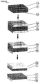
- Figure 1 presents schematically a representative process sequence in accordance with the invention, in four steps (from top to bottom), in perspective view. In the following reference signs are with respect to figure 1 .
- the basic raw material here is a monocrystalline silicon wafer 2, produced in accordance with the Czochralski-method as it is used, e.g., in the microelectronics or photovoltaics industry.
- the wafer 2 has a diameter of approximately 76mm and a thickness of approximately 0.4mm.
- the wafer is lightly n- or p-doped, has a specific electrical resistivity of approximately 10 Ohm cm, and its two faces 1a and 1b are oriented parallel to a ⁇ 100> crystal plane.
- One or both faces 1a and/or 1b of the wafer may be mirror-polished or simply etched and lapped.
- the wafer 2 can be used straight out of wafer production, or it can be roughly pre-cleaned using conventional methods (e.g., with organic solvents and water or by plasma oxidation cleaning).
- STEP 2 On each face 1a and 1b of the wafer 2 a thin layer 3a, 3b of polydiorganolsiloxane (e.g., polydimethylsiloxane, or PDMS; the ensuing discussions refer to PDMS for convenience, but it should be understood that any suitable silicone polymer or copolymer may be employed) is applied and cured (or allowed to cure).
- the preferred thicknesses of these auxiliary layers 3a, 3b are between 0.01mm and 10mm, with a thickness of between about 0.3 mm and about 3 mm more preferred.
- the thicknesses of the two layers 3a, 3b are the same in this illustrative embodiment, but in other embodiments the thicknesses of the two layers may differ.
- PDMS e.g., SYLGARD 184 by Dow Corning
- the liquid PDMS-mixture is first degassed approximately for one hour in vacuum, then it is applied on each face 1a, 1b of the wafer 2 in the desired thickness, and cured on a hotplate (e.g., for 30 minutes at 100°C).
- PDMS layers 3a, 3b have homogeneous thicknesses over most of the wafer area. This can be achieved by putting the wafer on a horizontal surface and letting the PDMS equilibrate by gravity before curing it.
- the three-layer composite (PDMS 3a - wafer 2 - PDMS 3b) is cooled down to room temperature. After that, any PDMS protruding along the circumference of the wafer 2 is removed with a sharp knife, such that the edge of the wafer 2 is essentially free of PDMS, and PDMS covers only the two faces 1a, 1b of the wafer 2. It is possible to avoid having any PDMS protrude over the circumference of the wafer (and thus touch the edge of the wafer) by applying the PDMS to the wafer faces carefully and letting it equilibrate on a horizontal surface; in this way the surface tension of the PDMS will keep it from overflowing onto the wafer edges.
- a tool such as a sharp knife or razor blade, is used to cut an arbitrary pattern 6 of lines and/or other geometrical figures (such as circles, etc.) into the surface of one of the PDMS layers 3a.
- all cuts have the same depth into the PDMS layer 3a, which is less than the thickness of the PDMS layer 3a (i.e., the PDMS layer 3a is nowhere cut completely through to the wafer surface 1a).
- preferred depths for these cuts range from 0.01 mm to 0.99mm, more preferably from 0.1mm to 0.9mm.
- STEP 4 After the patterning step, the composite (PDMS 3a - wafer 2 - PDMS (3b)) is completely immersed in a liquid nitrogen bath (temperature approximately -200°C). Due to the strongly differing thermal expansion coefficients of silicon (approximately 3*10 -6 K -1 ) and PDMS (approximately 300*10 -6 K -1 ), large mechanical stresses are induced in the composite by this cooling. However, in areas that are part of the pattern 6 where the PDMS layer 3a has been cut, the mechanical stresses are locally different, depending on the arrangement and depths of the cuts. After a few seconds of cooling, the wafer 2 splits spontaneously, parallel to its surface 1a, into two thin, monocrystalline silicon disks 5, with one side of each disk 5 still having the corresponding PDMS auxiliary layer 3a or 3b adhering.
- each of the two silicon disks 5 consists essentially of one single piece, with the face where the split occurred showing an image 7a or 7b of the pattern 6 on its surface 4.
- the image patterns 7a and 7b on the two silicon disks 5 are substantially complementary.
- the features in each of the image patterns 7a and 7b may comprise areas of different surface roughness, different surface heights (i.e., different local thicknesses of the corresponding silicon disk 5), or other differences in surface properties compared to the surrounding areas.
- the lateral characteristics of the pattern 6 are reproduced substantially in the complementary images 7a and 7b, at the same scale.
- Features in the pattern 6 that have lateral dimensions greater than about 0.1 mm can be replicated in the image patterns 7a and 7b.
- the disks 5 may - after the splitting - be transferred directly out of the liquid nitrogen bath onto a 100°C hotplate (with the side having the PDMS auxiliary layer 3a or 3b adhered facing down), until the whole PDMS auxiliary layer has warmed up again at least to room temperature.
- a 100°C hotplate with the side having the PDMS auxiliary layer 3a or 3b adhered facing down
- the disks 5 are carefully pressed against a flat support as they warm so that any curling of the layers is reversed, to flatten the layers as the warming proceeds.
- the thin silicon disks 5 with surface patterns 7a and 7b produced according to this method consist substantially of monocrystalline silicon with the same properties as the original wafer 2 and can be directly used.
- the PDMS auxiliary layers 3a or 3b can also be removed from the silicon disks 5, for example by immersion in an appropriate liquid etchant (e.g., a 3:1 mixture by volume of NMP (N-methylpyrrolidone) and TBAF/THF (tetrabutylammoniumfluoride, 1.0M solution in tetrahydrofuran), or also by immersion in hydrofluoric acid).
- an appropriate liquid etchant e.g., a 3:1 mixture by volume of NMP (N-methylpyrrolidone) and TBAF/THF (tetrabutylammoniumfluoride, 1.0M solution in tetrahydrofuran), or also by immersion in hydrofluoric acid).
- a preferred way for removing the PDMS auxiliary layers 3a or 3b is by rinsing with, or immersion in a bath of, hot sulfuric acid (H 2 SO 4 ) etchant, preferably at a temperature above 150°C (and more preferably above 200°C), then removing the produced white silica foam mechanically (e.g., using a brush, and possibly several brushing-etching cycles), and finally cleaning the silicon disk 5 by immersion in hydrofluoric acid.
- H 2 SO 4 hot sulfuric acid
- the patterning step (STEP 3) is performed using irradiation with a laser beam instead of cutting with a sharp knife.
- the laser preferably has a frequency that is strongly absorbed by PDMS (a CO 2 laser meets this criterion), and preferably the intensity and the motion of the beam over the PDMS layer 3a is controlled in an automated or manual fashion to cut a desired pattern.
- Commercially available laser cutters e.g., VERSA LASER VLS 6.60, with 60 Watt CO 2 laser are acceptable.
- the depth of the cut may be varied in any of several ways that may be employed individually or in combination: the laser beam can be focused at different depths, the laser intensity can be varied, the scanning speed of the laser beam over the PDMS surface 3a can be varied, the pulse rate of the laser can be changed, and the laser beam can be passed over the same spots on the PDMS surface 3a repeatedly (possibly with surface cleaning steps between passes).
- the patterning step is performed using chemical etching instead of cutting with a sharp knife, possibly using a mask layer on the surface of the PDMS, and possibly in combination with knife or laser cutting.
- the patterning step is performed by locally burning the PDMS surface 3a at selected locations, but instead of using a laser beam, a hot stamp featuring an embossed shape of the desired pattern is pressed onto the PDMS surface 3a.
- the hot stamp is preferably at a temperature above the PDMS decomposition temperature, more preferably above 550°C.
- the patterning step is performed using any of various possible cutting mechanisms, such as the ones mentioned earlier.
- the patterning step is performed using any of various possible cutting mechanisms, such as the ones mentioned earlier.
- lines cut into the PDMS surface 3a but so are laterally extended, two-dimensional features such as disks, which are also imposed into the PDMS surface 3a.
- This can be done by, for example, using a laser in a raster fashion to create these features based on image data used to control laser firing in the manner of a scanner.
- the patterning step in the present method is performed using any of various cutting mechanisms, such as the ones mentioned earlier.
- the depth of the cut is not kept constant throughout the pattern 6 but rather is locally varied in a pre-determined way.
- the features of the pattern 6 can be given different depths. In this way, for example, features with locally different heights can be produced in the image patterns 7a and 7b.
- cuts may be performed all the way through the PDMS layer 3a onto the surface 1a of the wafer 2.
- one of the two produced disks 5 will have an image pattern 7a of through-holes, and the other one will have the corresponding complementary pattern 7b of shaped mesas with the same thickness as the original wafer 2.
- the patterning step is performed not by cutting patterns into the PDMS auxiliary layer 3a, but rather by locally modifying the properties of the PDMS layer 3a at certain locations corresponding to the features of the desired pattern.
- the mechanical properties of PDMS, and in particular its CTE can be locally modified using the following technique [ Huck et al., Langmuir (2000), 16:3497-3501 ]: The PDMS layer 3a is soaked for 5 h in a 0.25 M solution of benzophenone in dichloromethane. The PDMS layer 3a is then dried for 24 hours in air, in the dark.
- UV light ultraviolet
- the PDMS layer 3a is then exposed to UV irradiation (e.g., 254 nm, 10-30 min) through an amplitude photomask showing the desired pattern 6.
- UV irradiation e.g., 254 nm, 10-30 min
- the exposed regions of the PDMS layer 3a become stiffer and less elastomeric, and have a CTE and elastic modulus that are different from those of the surrounding areas.
- the sensitized PDMS may instead be exposed, e.g., using a UV laser.
- selectively enhanced crosslinking of PDMS (which locally modifies its CTE and other mechanical properties that may influence local stress generation) at locations corresponding to the features of a desired pattern may be achieved, e.g., through irradiation with an infrared laser that selectively heats certain patterns on the surface of the PDMS layer 3a without burning it.
- the patterning step is performed not by cutting patterns into the PDMS auxiliary layer 3a, but rather by locally modifying the properties of the PDMS layer 3a at locations corresponding to features of the desired pattern.
- the mechanical properties of PDMS, and in particular its CTE and/or its elastic modulus can be locally modified by locally embedding other materials with different properties (such as different CTE and/or different elastic modulus) - glass beads, air bubbles, metal particles, fibres etc. - into the PDMS layer.
- the patterning step is performed by using a heterogeneous auxiliary layer 3a comprising at least one patterned layer and at least another non-patterned layer, possibly made from different materials, and possibly with different properties (such as different CTEs).
- a metal structure with the pattern 6 is deposited on the surface of the wafer 2, e.g., using screen printing techniques or lithography and physical vapor deposition.
- PDMS is then applied over both this metal structure and the wafer (thereby partially embedding the metal structure), and is then cured. Since for the metal structure properties such as the CTE are different from those of the PDMS, the produced thin disks 5 have surface structure patterns 7a and 7b that are substantially the images of the pattern 6 of the metal structure.
- the present method is used to split a wafer 2 into two thin disks 5, and the pattern 6 used is a mirror symmetric pattern.
- the properties of the PDMS auxiliary layers 3a and 3b may be chosen such that the thicknesses of the two produced thin disks 5 are the same, or that they are different from each other.
- the present method is used with a certain pattern 6 in the PDMS layer 3a on one side of the wafer, and another pattern 6' in the PDMS layer 3b on the other side of the wafer.
- the pattern 6' may be the same as the pattern 6, or it may be a different pattern.
- the image patterns 7a and 7b on the thin disks 5 that are produced by the method according to this embodiment are then substantially combinations (e.g., superpositions) of the patterns 6 and 6'.
- the present method is first used with a certain pattern 6 in the PDMS layer 3a and/or a pattern 6' in the PDMS layer 3b to produce two thin disks 5, one having a corresponding image pattern 7a and the other one a corresponding mirror image pattern 7b on one side.
- Each of the two disks 5 usually still has a PDMS layer 3a or 3b adhering on the other side.
- These layers may then be replaced with fresh PDMS layers, but it is preferred to leave these layers 3a and 3b adhering to their respective disk 5.
- these layers 3a and/or 3b may then be patterned if desired, or their pattern may be modified if they already were patterned (with patterns 6 or 6') during the first iteration of the method (i.e., for producing the two thin disks 5).
- the method is then applied again by depositing new PDMS auxiliary layers for the next iteration onto those sides of the two thin disks 5 that do not yet have a PDMS layer adhering (i.e., the sides having the surface structure patterns 7a or 7b). None, one or both of these new PDMS auxiliary layers may be patterned if desired (with any desired pattern).
- the second iteration of the method then produces a total of four thinner disks, where two out of those four thinner disks (in general) have locally controllable patterns of surface structures on both sides, i.e., comparable to double-sided printing: On one side they have an image pattern 7a (or its mirror image 7b, respectively) corresponding to a superposition of the patterns 6 and 6' in the old PDMS auxiliary layers 3a and 3b during the first iteration, and on the other side they have an image pattern that corresponds to a superposition of any (possibly modified) pattern in the old PDMS auxiliary layers 3a (or 3b) and any pattern in the corresponding new PDMS auxiliary layer.
- a stress pattern instead of having a pattern 6 of regions with locally different CTE in the PDMS layer 3a and subjecting the composite structure to a temperature change, it is also possible to employ other mechanisms to induce locally differing stresses (i.e., a stress pattern) in the PDMS layer 3a.
- a stress pattern instead of using the same temperature change for the whole PDMS auxiliary layer, different temperature changes may be imposed at different locations in the PDMS auxiliary layer, for example, by selectively cooling certain areas in the auxiliary layer more strongly than others, e.g. using contact with a cooled stamp that has the desired pattern 6 embossed, or by cooling the whole layer and selectively re-heating certain areas e.g. with a laser.
- auxiliary layer for this embodiment it is preferred to use an auxiliary layer material with relatively low thermal conductivity, such as PDMS.
- locally definable stress patterns can be produced by subjecting the auxiliary layer to patterns 6 of locally varying, externally applied physical or chemical conditions (that may furthermore also be temporally varying), e.g. light patterns, heat patterns (different areas having different temperature), solvent patterns (different areas having different solvent concentrations), patterns of electric or magnetic fields, patterns of external mechanical forces acting on the auxiliary layer, etc.
- the auxiliary layer preferably comprises at least one material that interacts with these patterns 6 of externally applied physical or chemical conditions by (locally) changing its volume (e.g., a material that expands under UV light, or in an electric/magnetic field, etc).
- another alternative method for inducing patterns of locally differing stresses is to include active devices such as piezo-electric actuators at certain locations in the PDMS layer 3a and actuate them (e.g., electrically, optically) to generate a stress pattern in the PDMS layer 3a.
- active devices such as piezo-electric actuators at certain locations in the PDMS layer 3a and actuate them (e.g., electrically, optically) to generate a stress pattern in the PDMS layer 3a.
- locally definable stress patterns can be produced by embedding, into the PDMS layer 3a, patterns 6 of different materials that undergo different volume changes when activated by a chemical or physical mechanism.
- Mechanisms that can achieve such a volume change include, in addition to temperature change, a change in humidity (e.g., swelling, de-hydration), a change of solvent composition and/or ionic strength (e.g., osmotic pressure actuators, polyelectrolyte gels, ionic polymer metal composites, conducting polymers, carbon nanotube actuators), a change of pH, phase changes (e.g., freezing of embedded solvent), chemical reactions (e.g., polymer gels), electric activation (e.g., piezoelectric or electrostrictive materials, electrostatic actuators, electro-active polymers), magnetic activation (e.g., "magnetic" gels), optical activation (e.g., liquid crystal elastomers, photo-reactive materials), etc, as well as combinations of any or all of those.
- a change in humidity e.g., swelling, de-hydration
- solvent composition and/or ionic strength e.g., osmotic pressure actuators, poly
- the PDMS layer 3a instead of locally embedding patterns of different materials into the PDMS layer 3a it is possible to locally modify the PDMS itself (chemically) in order to achieve the desired locally different volume changing behavior, e.g., by locally adding different functional side chains to the polymer, or locally changing the degree of cross-linking e.g., by UV irradiation.
- the initiation of the splitting in step 4 is facilitated and control of the splitting process is improved by providing the wafer 2 with one or more structurally weaker zones at certain specific locations on the wafer surface. For example, one or more small defect zones can be created at the edge of the wafer 2.
- Such defect zones can be created mechanically (e.g., by hitting a certain spot on the wafer edge with a sharp pointed hammer, thereby locally shattering the crystal structure and creating a dent or nick, or by sawing, filing, or milling, etc., in order to create a groove or notch), chemically (e.g., locally etching a groove), optically (e.g., locally melting the material using a laser, or ablating it to create groove structures), or by other suitable mechanisms. Splitting will then preferentially start at those defect zones and propagate over the rest of the wafer area from there.
- this is advantageous since by varying the location of these defect zones it is possible to better control the initial depth of the splitting, i.e., the thickness of the produced thin disks 5 at their edges, and in general improve the quality of the edges of the disks 5.
- a groove in the edge (i.e., around the circumference) of the wafer 2 half-way in-between the two faces 1a and 1b may facilitate splitting into two thin disks 5 of equal thickness and with clean-cut edges.
- the weaker zones according to this embodiment may be created before stress is induced in the work piece (e.g., before cooling), or they may be created while the wafer is already under stress.
- the second method also allows to better control the moment in time when splitting starts: If stress is built up in the wafer up to a magnitude just slightly below the critical value where the splitting process would begin spontaneously, then, as soon as a weakness is created, splitting will start, preferentially from the location of that weakness.
- the initiation of the splitting in step 4 is facilitated by subjecting the wafer 2 to controlled shock, e.g., a short shock wave.
- a shock wave in the wafer can be induced by one or more controlled blows with a mechanical device such as a hammer (peening), by delivering ultrasonic pulses, or by strong laser pulses, etc.
- a mechanical device such as a hammer (peening)
- ultrasonic pulses or by strong laser pulses, etc.
- the spatial distribution, intensity and temporal characteristics of such shock waves facilitates modulation of and better control over the splitting process.
- the present method is used on a wafer 2 that already has existing surface structures on at least one of its two faces 1a or 1b.
- Such existing surface structures can be formed from the wafer material itself, or they can involve additional materials (e.g., metallic contacts, anti-reflection layers, dielectric layers, epitaxial layers, etc.), or any combination thereof.
- the PDMS is then applied over these existing structures, covering and conformally surrounding them, so that after curing the PDMS these existing structures become partially embedded in the PDMS layers 3a and/or 3b.
- the pre-existing surface structures on the faces 1a and/or 1b may somewhat influence the stress patterns and thus the produced surface structures 7a and 7b, however, this influence is often small (since the thickness of the pre-existing surface structures is often much smaller than the thickness of the disks) any it may also be compensated using appropriate patterning of the auxiliary layers 3a and/or 3b.
- the present method is used on a wafer 2 that already has existing internal (bulk) structures, such as, e.g., one or more dopant gradients.
- existing internal (bulk) structures such as, e.g., one or more dopant gradients.
- the present method is used on a wafer 2 that already has both existing surface structures and existing internal (bulk) structures.
- the wafer has partially or completely functional devices (electronic, optical, micro-mechanical, chemical, etc.) on one or both of its faces 1a and/or 1b.
- Such devices may include LEDs, laser diodes, solar cells, tandem solar cells, power amplifiers, integrated circuits in general, micro-electromechanical devices such as sensors or actuators, etc.
- the PDMS is then applied over these existing devices on the wafer faces, covering the devices, and conformally surrounding them on the outside, so that after curing the PDMS these existing devices become partially embedded in the PDMS layers 3a and/or 3b.
- the surface structures and internal structures that make up the front part (i.e., the side that is illuminated during normal operation) of a conventional silicon solar cell e.g., front-side doped layer including pn-junction, front metal contact grid, anti-reflective coating
- front-structures are considered and in the following referred to as "front-structures.”
- front-structures are manufactured onto both sides 1a and 1b of a thick mono-crystalline silicon wafer 2.
- this wafer 2 is split into two thinner disks 5 as described above, whereby the device layers are preserved, such that each of these two disks 5 now has “front-structures" but only on one side (i.e., the side still having the corresponding PDMS layer 3a or 3b adhered).
- On the other side of each of the two disks 5 is a "fresh" surface consisting of bulk wafer material, with a surface structure 7a or 7b determined by a pattern 6 in the PDMS.
- the "fresh" surfaces of both disks can now be further processed using conventional methods for making the back sides of silicon solar cells (e.g., back -surface field doping, back-side contact metallization, etc.), completing the manufacturing of two silicon solar cells.
- This example shows a number of advantages: most of the solar cell manufacturing steps can be done on a relatively thick (and therefore less fragile) wafer 2, which facilitates use of inexpensive processes such as screen-printing of the contacts, and simplifies wafer handling in general. Also, the same (front-side) dopant can be diffused into the whole surface of the wafer, i.e., into both its sides 1a and 1b, and there is no need, for example, to subsequently remove the dopant from the back of the wafer (since that is automatically achieved by the splitting process).
- an anti-reflection coating which can also be produced on the whole wafer (e.g., oxidative growth of SiO 2 and/or PECVD deposition of Si 3 N 4 nitride) and then automatically is confined to one side through the splitting process.
- an anti-reflection coating which can also be produced on the whole wafer (e.g., oxidative growth of SiO 2 and/or PECVD deposition of Si 3 N 4 nitride) and then automatically is confined to one side through the splitting process.
- a number of processing steps for solar cell manufacturing can be eliminated or simplified by application of the present method.
- both of the produced thin disks 5 are almost-finished back-contact cells already (possibly only requiring deposition of an anti-reflection coating on the other side). Therefore, the present method can be applied to produce thin, mono-crystalline silicon back-contact solar cells without the need for handling thin wafers through most of the process.
- the invention in another aspect, relates to a device comprising a slab (block, ingot, disk, etc.) of a solid state material divided by a gap into two pieces, one piece being the geometrical complement of the other piece, so that by reducing the gap to zero, the shape, dimensions and mass of the original slab can be retrieved, substantially without any material missing (e.g., without internal voids, etc.).
- At least one of those two pieces is a thin layer, i.e., it is substantially a flat or curved sheet having an area of at least 1cm 2 , and throughout this area its thickness is smaller than 2mm, preferably smaller than 0.5mm.
- At least one of the thin-layer pieces itself has a layer of at least one additional solid state material (referred to as auxiliary layer) adhered to it on the face opposite to the gap.
- auxiliary layer additional solid state material
- those surfaces facing the gap do not contain materials other than the ones that are found in the bulk of the slab (except possibly for, e.g., a native oxide layer if the surfaces are reactive with and exposed to air).
- the invention relates to a device as described above but where, for each of the two pieces, the surfaces facing the gap show a structure according to some pattern, with the surface structures 7a on one piece being substantially complementary to the surface structures 7b on the other piece, and with the pattern being substantially a full-size image of a corresponding pattern 6 in at least one layer of at least one additional solid state material (auxiliary layer) adhered to at least one of the two pieces.
- the pattern 6 in the auxiliary layer is realized by having parts of the auxiliary layer exhibit local material properties (such as locally different CTE or locally different elastic modulus) different from those of the surrounding areas, which, for example, may include parts where the material of the auxiliary layer is partially or completely removed (i.e., void structures).
- the pattern 6 may be a pattern of stresses that is temporarily induced in the auxiliary layer by applying patterns of external physical or chemical influences on the auxiliary layer, such as light patterns, heat patterns, patterns of external mechanical forces acting on the auxiliary layer, etc.
- the approach of the present invention can also be used to produce thin, free-standing layers with structured surfaces from work pieces that consist of solid state materials other than monocrystalline silicon (e.g., polycrystalline silicon, sapphire, germanium, quartz, or amorphous materials such as glass). Also, this approach can be used with work pieces that are composed of several different materials (homogeneous or inhomogeneous composite materials, etc.) or that have an internal structure (laminates, etc.). For example, the approach can be used for work pieces consisting of a monocrystalline silicon wafer with an epitaxially grown layer such as gallium nitride (GaN) on its surface.
- GaN gallium nitride
- auxiliary layers materials other than PDMS - e.g., other polysiloxanes (which can include organometallic groups for, e.g., electric activity) other elastomers, other polymers or plastics in general, or metals such as aluminum or silver, etc. - may be used. It is also possible to utilize auxiliary layers that are composed of several different materials (homogeneous or inhomogeneous composite materials, etc.) or that have an internal structure (laminates, etc.). In general, the work piece is a relatively brittle solid state material. Good adhesion between work piece and auxiliary layer should be achieved and maintained throughout the process, and the auxiliary layer should be amenable to convenient processes for imposing sufficiently strong stress patterns without breaking the auxiliary layer itself.
- the PDMS (or other polymer) in the auxiliary layer can be cured (i.e., its polymer chains cross-linked) by means other than heating it on a hotplate.
- it may be heated by blowing a hot gas over it, or irradiating it with, e.g., infrared light.
- curing may be accomplished using chemical additives, ultraviolet radiation, or electron beam.
- the PDMS (or other polymer, or in general any material in the auxiliary layer) may also be chemically modified to facilitate a particular form of cure (or, in general, solidifying, possibly generating internal stress inside the layer during solidification already), for example, curing PDMS by UV irradiation may be facilitated, e.g., by immersing the PDMS in benzophenone (a photosensitizer that generates radicals under irradiation), or by, e.g., replacing the methyl groups in the PDMS with photoreactive substituents.
- benzophenone a photosensitizer that generates radicals under irradiation
- auxiliary layer may also be removed mechanically, by irradiation, electron beam, and/or heat.
- a PDMS auxiliary layer can be mechanically peeled off from a thin disk 5 of monocrystalline silicon if the face of the disk opposite to the PDMS layer is temporarily fixed (e.g., glued) to a support, and then, e.g., starting from a corner, the PDMS is slowly and carefully peeled off by pulling it in a direction substantially vertical to the surface of the disk, possibly facilitated by inserting a wedge or similar item between the PDMS layer and the disk 5.
- PDMS or other polymers
- PDMS may also be removed by ashing in a plasma, e.g., in an oxygen plasma.
- the PDMS may also be chemically modified such that it decomposes more easily, e.g., under UV irradiation.
- the present approach can be applied to work pieces of almost arbitrary shape and is not limited to planar wafers.
- the present invention may be used, e.g., to peel off thin sheets with structured surfaces directly from a mono-crystalline silicon ingot that is flattened on one side.
- the work piece used is confined by at least one flat surface.
- the auxiliary layer is then applied. It is possible to only peel off one sheet, or several sheets can be peeled off from different surfaces of a work piece at the same time.
- the present approach can also be applied for producing thin, free-standing curved sheets or shells with structured surfaces.
- the auxiliary layer is applied onto a correspondingly curved surface of the work piece.
- the temperature change then leads to the splitting off of a thin, correspondingly curved sheet or shell from the remainder of the work piece along a patterned fracture zone inside the work piece.
- This patterned fracture zone runs everywhere approximately at the same distance to the interface between work piece and auxiliary layer, so that the produced sheet with surface structure patterns has an approximately uniform thickness (except for the patterns 7a and 7b, where thickness variations may be deliberately produced)
- the surface properties of the surface onto which the auxiliary layer is applied are not critical.
- the interface may be smoothly polished, or it may have significant roughness. It is only important to retain adequate adhesion to the auxiliary layer.
- the fracture surface which is formed on the remainder of the work piece when peeling off a sheet from the work piece, can be used subsequently as the surface onto which the auxiliary layer is applied.
- the present approach can be reapplied on the remainder of the work piece. In this way sheet after sheet can be successively peeled off from a single work piece.
- a monocrystalline silicon wafer can be split into two disks with structured surfaces by applying PDMS auxiliary layers onto both sides; neither, one or both of these auxiliary layers can have a pattern 6, and if both have patterns, these patterns can be the same or different from each other.
- Each of these produced two thinner disks can then again be provided on both sides with a PDMS auxiliary layer, again with neither, one or both of them having patterns (6) that may be the same or different, and, repeating the steps of the method, can thus be further split into two even thinner disks with structured surfaces (having different surface structure patterns, if desired), and so on.
- a large number of thin monocrystalline disks with structured surfaces can be obtained from a single monocrystalline silicon wafer.
- eight approximately 50 ⁇ m thick disks with custom structured surfaces can be obtained from a customary 0.4mm thick wafer.
- the dimensions of the thus-produced thin, free-standing layers can be set through appropriate choice of the stress inducing mechanism (e.g., the temperature change), and/or the properties of the auxiliary layer. This is achieved in particular through appropriate choice of the time flow of the stress induction, the magnitude of the stress induced, the dimensions of the auxiliary layer, the geometric shape of the auxiliary layer, and/or the mechanical and/or thermal/optical/chemical/hydrostatic/piezoelectric/etc properties of the auxiliary layer.
- the stress inducing mechanism e.g., the temperature change
- the auxiliary layer may, e.g., be applied in liquid or gaseous state onto the corresponding surface of the work piece, and then be solidified there. Alternatively, the auxiliary layer can also be adhered directly in the solid state onto the surface.
- the adhesion between the auxiliary layer and the surface of the work piece can be achieved through chemical bonding, van-der-Waals forces, or other strong adhesive forces. Also an adhesion through alloying of auxiliary layer and work piece material at the interface, or adhering the auxiliary layer by means of a third material (e.g., an adhesive) onto the surface of the work piece, are possible for the implementation of the present method.
- liquid nitrogen instead of liquid nitrogen, other coolants (e.g., liquid helium, ice water, or cooling solids or cooling gases, etc.) may be used to build up, by cooling, the necessary mechanical stresses inside the auxiliary-layer-work-piece composite. In certain cases it is sufficient to simply cool down the composite to room temperature, so that a special coolant will not be needed. Furthermore, it is possible in certain cases to achieve the necessary mechanical stresses inside the composite by warming up instead of cooling down. Essential for building up the necessary mechanical stresses at a certain temperature T are a sufficiently large difference in thermal expansion between work piece and at least parts of the auxiliary layer, as well as a sufficiently large difference between the temperature T and the temperature at which the auxiliary layer was adhered onto the work piece.
- coolants e.g., liquid helium, ice water, or cooling solids or cooling gases, etc.
- an independent method for producing thin, free-standing layers of solid state materials by stress-induced splitting (spalling) from a work piece in particular a method that enables the use of inexpensive and little-contaminating materials such as polymers in a stress inducing auxiliary layer.
- the work piece 2 is a commercially available monocrystalline silicon wafer.
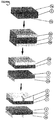
- Figure 2 presents schematically a representative process sequence in accordance with the invention, in four steps (from top to bottom), in perspective view. In the following reference is made to figure 2 .
- the basic raw material here is a monocrystalline silicon wafer 2, produced in accordance with the Czochralski-method as it is used, e.g., in the microelectronics or photovoltaics industry.
- the wafer 2 has a diameter of approximately 76mm and a thickness of approximately 0.4mm.
- the wafer is lightly n- or p-doped, has a specific electrical resistivity of approximately 10 Ohm cm, and its two faces 1a and 1b are oriented parallel to a ⁇ 100> crystal plane.
- One or both faces 1a and/or 1b of the wafer may be mirror-polished or simply etched and lapped.
- the wafer 2 can be used straight out of wafer production, or it can be roughly pre-cleaned using conventional methods (e.g., with organic solvents and water, or by plasma oxidation cleaning).
- STEP 2 On each face 1a and 1b of the wafer 2 a thin layer 3a and 3b of polydiorganolsiloxane (e.g., polydimethylsiloxane, or PDMS; the ensuing discussions refers to PDMS for convenience, but it should be understood that any suitable silicone polymer or copolymer may be employed) is applied and cured (or allowed to cure).
- the preferred thicknesses of these auxiliary layers 3a and 3b are between 0.01mm and 10mm, with a thickness of between about 0.1 mm and about 1 mm more preferred.
- the thicknesses of the two layers 3a, 3b are the same in this illustrative embodiment, but in other embodiments the thicknesses of the two layers can differ.
- PDMS e.g., SYLGARD 184 by Dow Corning
- the liquid PDMS-mixture is first degassed approximately for one hour in vacuum, then it is applied on each face 1a, 1b of the wafer 2 in the desired thickness, and cured on a hotplate (e.g., for 30 minutes at 100°C).
- PDMS layers 3a, 3b have homogeneous thicknesses over most of the wafer area. This can be achieved by putting the wafer on a horizontal surface and letting the PDMS equilibrate by gravity before curing it.
- the three-layer composite (PDMS 3a - wafer 2 - PDMS 3b) is cooled down to room temperature. After that, any PDMS protruding along the circumference of the wafer 2 is removed with a sharp knife, such that the edge of the wafer 2 is essentially free of PDMS, and PDMS covers only the two faces 1a and 1b of the wafer 2. It is possible to avoid having any PDMS protrude over the circumference of the wafer (and thus touch the edge of the wafer) by applying the PDMS to the wafer face carefully and letting it equilibrate on a horizontal surface; in this way the surface tension of the PDMS will keep it from overflowing onto the wafer edges.
- STEP 3 The composite (PDMS 3a - wafer 2 - PDMS 3b) is completely immersed in a liquid nitrogen bath (temperature approximately -200°C). Due to the strongly differing thermal expansion coefficients of silicon (approximately 3*10 -6 K -1 ) and PDMS (approximately 300*10 -6 K -1 ), large mechanical stresses are induced in the composite by this cooling. After the PDMS layers 3a, 3b have substantially reached thermal equilibrium with the surrounding liquid nitrogen bath (e.g., when the intensive "bubbling" in the liquid nitrogen around the PDMS layers 3a, 3b ceases), the composite is taken out of the bath again, exposed to room temperature, and allowed to warm up for a very short time.
- a liquid nitrogen bath temperature approximately -200°C
- This warm up time is preferably chosen short enough that at least some parts of the PDMS layers 3a and 3b still are at temperatures below the glass transition temperature of PDMS (-125°C), and long enough that at least some parts of the PDMS layers 3a, 3b achieve temperatures above the glass transition temperature of PDMS.
- a preferred warm up time is between 1 and 5 seconds for 0.4 mm thick layers of PDMS. This leads to non-homogeneous physical conditions inside the auxiliary layer, i.e., the temperature distribution inside the PDMS layers 3a and 3b is non-homogeneous, with temperatures ranging from approximately room temperature down to approximately -200°C.
- the glass transition temperature of PDMS is approximately -125°C, and since PDMS becomes relatively stiffer (i.e., larger elastic modulus) at temperatures below the glass transition temperature, this results in the PDMS layers 3a and 3b being stiffer (i.e., larger elastic modulus) towards their interfaces with the wafer 2 and softer (smaller elastic modulus) on their outside.
- STEP 4 After the short warm up time, the wafer 2 is hit e.g. with a sharp pointed hammer (peening) at a specific location in the side of the wafer 2, i.e., at a point along its edge, which is not covered by the PDMS layers 3a and 3b. This leads to a locally weak zone or defect in the wafer 2, which in turn triggers a fracture process: The wafer 2 splits spontaneously, in a substantially single, uninterrupted crack propagation movement, parallel to its surface 1a, into two thin, monocrystalline silicon disks 5, with one side of each disk 5 still having the corresponding PDMS auxiliary layer 3a or 3b adhering.
- peening a sharp pointed hammer
- each of the two silicon disks 5 consists essentially of one single piece.
- the disks 5 may - directly after the splitting - be transferred onto a 100°C hotplate (with the side having the PDMS auxiliary layer 3a or 3b adhered facing down), until the whole PDMS auxiliary layer has warmed up again at least to room temperature.
- the disks 5 are carefully pressed against a flat support as they warm so that any curling of the layers is reversed, to flatten the layers as the warming proceeds.
- the thin silicon disks 5 produced according to this method consist substantially of monocrystalline silicon with the same properties as the original wafer 2 and can be directly used.
- the PDMS auxiliary layers 3a or 3b can also be removed from the silicon disks 5, for example by immersion in an appropriate liquid etchant (e.g., a 3:1 mixture by volume ofNMP (N-methylpyrrolidone) and TBAF/THF (tetrabutylammoniumfluoride, 1.0M solution in tetrahydrofuran), or also by immersion in hydrofluoric acid).
- an appropriate liquid etchant e.g., a 3:1 mixture by volume ofNMP (N-methylpyrrolidone) and TBAF/THF (tetrabutylammoniumfluoride, 1.0M solution in tetrahydrofuran), or also by immersion in hydrofluoric acid).
- a preferred way for removing the PDMS auxiliary layers 3a or 3b is by rinsing with, or immersion in a bath of, hot sulfuric acid (H2SO4) etchant, preferably at a temperature above 150°C (and more preferably above 200°C), then removing the produced white silica foam mechanically (e.g., using a brush, and possibly several brushing-etching cycles), and finally cleaning the silicon disk 5 by immersion in hydrofluoric acid.
- H2SO4 hot sulfuric acid
- the fracture initiation step is performed while the composite (PDMS 3a - wafer 2 - PDMS 3b) is still immersed in the liquid nitrogen bath, i.e., during cooling down or after thermal equilibrium with the surrounding liquid nitrogen bath has been reached.
- the short intermediate warm up time is omitted.
- the warm up time in STEP 3 may be extended, such that the thermally induced stresses are no longer large enough for fracturing to start when hitting the wafer 2 with a sharp pointed hammer during STEP 4.
- the composite (PDMS 3a - wafer 2 - PDMS 3b) is again cooled down by immersing into the liquid nitrogen bath, which then leads to spontaneous start of the fracturing process.
- a locally weak zone or defect in the wafer 2 during STEP 4 external stress is applied at certain locations on the outside of the composite (PDMS 3a - wafer 2 - PDMS 3b), which then triggers the fracture (spalling) process by locally increasing stress intensity above the fracture toughness threshold of the wafer material.
- a locally weak zone or defect in the wafer 2 is created before the cooling step (STEP 3).
- this creating of a weak zone does not trigger the fracture process, but allows to define a location where fracture will preferably start once sufficient stress has been built up in the wafer 2 by cooling it down in STEP 3 (fracturing will then start spontaneously in this case, but may also be additionally triggered using any of the above methods).
- a PDMS layer 3a with a CTE differing substantially from the CTE of the wafer 2 and subjecting the composite structure to a temperature change it is also possible to employ other mechanisms to create pre-definable stress patterns in the PDMS layer 3a that can induce the required stress pattern in the wafer 2.
- One such alternative method is to include piezo-electric actuators at certain positions in the PDMS layer 3a and electrically actuate them to generate a stress pattern in the PDMS layer 3a. More generally, locally definable stress patterns can be produced by embedding, into the PDMS layer 3a, patterns of different materials that undergo different volume changes when activated by a chemical or physical mechanism.
- Mechanisms that can achieve such a volume change include, in addition to temperature change, a change in humidity (e.g., swelling, de-hydration), a change of solvent composition and/or ionic strength (e.g., osmotic pressure actuators, polyelectrolyte gels, ionic polymer metal composites, conducting polymers, carbon nanotube actuators), a change of pH, phase changes (e.g., freezing of embedded solvent, crystallization, vaporizing), chemical reactions (e.g., polymer gels), electric activation (e.g., piezoelectric or electrostrictive materials, electrostatic actuators, electro-active polymers), magnetic activation (e.g., "magnetic" gels), optical activation (e.g., liquid crystal elastomers, photo-reactive materials), etc, as well as combinations of any or all of those.
- a change in humidity e.g., swelling, de-hydration
- solvent composition and/or ionic strength e.g., o
- PDMS layer 3a instead of locally embedding different materials into the PDMS layer 3a it is possible to locally modify the PDMS itself (chemically) in order to achieve the desired locally different volume changing behavior, e.g., by locally adding different functional side chains to the polymer, or locally changing the degree of cross-linking e.g., by UV irradiation.
- the present method is used on a wafer 2 that has existing surface structures on at least one of its two faces 1a or 1 b.
- Such existing surface structures can be formed from the wafer material itself, or they can involve additional materials (e.g., metallic contacts, anti-reflection layers, dielectric layers, epitaxial layers, etc.), or any combination thereof.
- the PDMS is then applied over these existing structures, covering and conformally surrounding them, so that after curing the PDMS these existing structures become partially embedded in the PDMS layers 3a and/or 3b.
- the present method is used on a wafer 2 that has existing internal (bulk) structures, such as, e.g., one or more dopant gradients.
- existing internal (bulk) structures such as, e.g., one or more dopant gradients.
- the present method is used on a wafer 2 that has both existing surface structures and existing internal (bulk) structures.
- the wafer has partially or completely functional devices (electronic, optical, micro-mechanical, chemical, etc.) on one or both of its faces 1a and/or 1b.
- Such devices may include LEDs, laser diodes, solar cells, tandem solar cells, power amplifiers, integrated circuits in general, micro-electromechanical devices such as sensors or actuators, etc.
- the PDMS is then applied over these existing devices on the wafer faces, covering the devices, and conformally surrounding them on the outside, so that after curing the PDMS these existing devices become partially embedded in the PDMS layers 3a and/or 3b.
- the surface structures and internal structures that make up the front part of a conventional silicon solar cell are considered and in the following referred to as "front-structures.”
- front-structures e.g., front-side doped layer including pn-junction, front metal contact grid, anti-reflective coating
- front-structures are manufactured onto both sides 1a and 1b of a thick mono-crystalline silicon wafer 2.
- this wafer 2 is split into two thinner disks 5 as described above, whereby the device layers are preserved, such that each of these two disks 5 now has “front-structures" but only on one side (i.e., the side still having the corresponding PDMS layer 3a or 3b adhered).
- On the other side of each of the two disks 5 is a "fresh" surface consisting of bulk wafer material.
- the "fresh" surfaces of both disks can now be further processed using conventional methods for making the back sides of silicon solar cells (e.g., back-surface field doping, back-side contact metallization, etc.), completing the manufacturing of two silicon solar cells.
- This example shows a number of advantages: most of the solar cell manufacturing steps can be done on a relatively thick (and therefore less fragile) wafer 2, which facilitates use of inexpensive processes such as screen-printing of the contacts, and simplifies wafer handling in general. Also, the same (front-side) dopant can be diffused into the whole surface of the wafer, i.e., into both its sides 1a and 1b, and there is no need, for example, to subsequently remove the dopant from the back of the wafer (since that is automatically achieved by the splitting process).
- an anti-reflection coating which can also be produced on the whole wafer (e.g., oxidative growth of SiO2 and/or PECVD deposition of Si3N4 nitride) and then automatically is confined to one side through the splitting process.
- an anti-reflection coating which can also be produced on the whole wafer (e.g., oxidative growth of SiO2 and/or PECVD deposition of Si3N4 nitride) and then automatically is confined to one side through the splitting process.
- a number of processing steps for solar cell manufacturing can be eliminated or simplified by application of the present method.
- both of the produced thin disks 5 become almost-finished back-contact cells already (possibly only requiring deposition of an anti-reflection coating on the other side). Therefore, the present method can be applied to produce thin, mono-crystalline silicon back-contact solar cells without the need for handling thin wafers through most of the process.
- the invention in another aspect, relates to a device comprising a slab (block, ingot, disk, etc.) of a solid state material divided by a gap into two pieces, one piece being the geometrical complement of the other piece, so that by reducing the gap to zero, the shape, dimensions and mass of the original slab can be retrieved, substantially without any material missing (e.g., internal voids, etc.).
- At least one of those two pieces is a thin layer, i.e., it is substantially a flat or curved sheet having an area of at least 1cm 2 , and throughout this area its thickness is smaller than 2mm, preferably smaller than 0.5mm.
- At least one of the thin-layer pieces itself has a layer of at least one additional solid state material (auxiliary layer) with locally varying material properties (e.g., locally varying elastic modulus) adhered to it on the face opposite to the gap.
- auxiliary layer additional solid state material
- locally varying material properties e.g., locally varying elastic modulus
- the approach of the present invention can also be used to produce thin, free-standing layers from work pieces that consist of solid state materials other than monocrystalline silicon (e.g., polycrystalline silicon, sapphire, germanium, quartz, zinc oxide, or amorphous materials such as glass). Also, this approach can be used with work pieces that are composed of several different materials (homogeneous or inhomogeneous composite materials, etc.) or that have an internal structure (laminates, etc.).
- solid state materials e.g., polycrystalline silicon, sapphire, germanium, quartz, zinc oxide, or amorphous materials such as glass.
- this approach can be used with work pieces that are composed of several different materials (homogeneous or inhomogeneous composite materials, etc.) or that have an internal structure (laminates, etc.).
- auxiliary layers materials other than PDMS - e.g., other polysiloxanes (which can include organometallic groups for, e.g., electric activity), other elastomers, other polymers or plastics in general, or metals such as aluminum or silver, etc. - may be used. It is also possible to utilize auxiliary layers that are composed of several different materials (homogeneous or inhomogeneous composite materials, etc.) or that have an internal structure (laminates, etc.). In general, the work piece is a relatively brittle solid state material. Good adhesion between work piece and auxiliary layer should be achieved and maintained throughout the process, and the auxiliary layer should be amenable to convenient processes for imposing sufficiently strong stress patterns without breaking the auxiliary layer itself.
- the PDMS (or other polymer) in the auxiliary layer can be cured (i.e., its polymer chains cross-linked) by means other than heating it on a hotplate.
- it may be heated by blowing a hot gas over it, or irradiating it with, e.g., infrared light.
- curing may be accomplished using chemical additives, ultraviolet radiation, or electron beam.
- the PDMS (or other polymer, or in general any material in the auxiliary layer) may also be chemically modified to facilitate a particular form of cure (or, in general, solidifying, possibly generating internal stress inside the layer during solidification already), for example, curing PDMS by UV irradiation may be facilitated, e.g., by immersing the PDMS in benzophenone (a photosensitizer that generates radicals under irradiation), or by, e.g., replacing the methyl groups in the PDMS with photoreactive substituents.
- benzophenone a photosensitizer that generates radicals under irradiation
- a number of alternative methods may be used to remove the auxiliary layer from the disks 5 at the end of the process.
- the layer may also be removed mechanically, by irradiation, electron beam, and/or heat.
- a PDMS auxiliary layer can be mechanically split off from a thin disk 5 if the face of the disk opposite to the PDMS layer is temporarily fixed (e.g., glued) to a support, and then, e.g., starting from a corner, the PDMS is slowly and carefully split off by pulling it in a direction substantially vertical to the surface of the disk.
- PDMS may simply be heated up, e.g., with a laser or in an oven, above its decomposition temperature (i.e., removal by ashing). It may also be removed by ashing in a plasma, e.g., in an oxygen plasma.
- the PDMS may also be chemically modified such that it decomposes more easily, e.g., under UV irradiation or when exposed to heat.
- the present approach can be applied to work pieces of almost arbitrary shape and is not limited to planar wafers.
- the present invention can be used, e.g., to split off thin sheets directly from a mono-crystalline silicon ingot that is flattened on one side.
- To split off a flat sheet it is sufficient that the work piece used is confined by at least one flat surface.
- On this interface the auxiliary layer is then applied. It is possible to only split off one sheet, or several sheets can be split off from different interfaces of a work piece at the same time.
- the present approach can also be applied for producing thin, free-standing curved sheets or shells. To this end, the auxiliary layer is applied onto a correspondingly curved surface of the work piece.
- the temperature change then leads to the splitting off of a thin, correspondingly curved sheet or shell from the remainder of the work piece along a patterned fracture zone inside the work piece.
- This patterned fracture zone runs everywhere approximately at the same distance to the interface between work piece and auxiliary layer, so that the produced sheet with surface structure patterns has an approximately uniform thickness.
- the surface properties of the interface onto which the auxiliary layer is applied are not critical.
- the interface may be smoothly polished, or it may have significant roughness. It is only important to retain adequate adhesion to the auxiliary layer.
- the fracture surface which is formed on the remainder of the work piece when splitting off a sheet from the work piece, can be used subsequently as the interface onto which the auxiliary layer is applied.
- the present approach can be reapplied on the remainder of the work piece. In this way sheet after sheet can be successively split off from a single work piece.
- a monocrystalline silicon wafer can be split into two disks by applying PDMS auxiliary layers onto both sides.
- Each of these two thinner disks can then again be provided on both sides with a PDMS auxiliary layer, and, repeating the steps of the method, can thus be further split into two even thinner disks, and so on.
- a large number of thin monocrystalline disks can be obtained from a single monocrystalline silicon wafer. For example, in three steps, eight approximately 50 micrometer thick disks can be obtained from a customary 0.4 mm thick wafer.
- the dimensions of the thus-produced thin, free-standing layers can be set through appropriate choice of the stress inducing mechanism (e.g., the temperature change), and/or the properties of the auxiliary layer. This is achieved in particular through appropriate choice of the time flow of the stress induction, the magnitude of the stress induced, the dimensions of the auxiliary layer, the geometric shape of the auxiliary layer, and/or the local mechanical and/or local thermal/chemical/hydrostatic/piezoelectric/etc properties of the auxiliary layer.
- the stress inducing mechanism e.g., the temperature change
- the auxiliary layer can, e.g., be applied in liquid or gaseous state onto the corresponding interface of the work piece, and then be solidified there. Alternatively, the auxiliary layer can also be adhered directly in the solid state onto the interface.
- the adhesion between auxiliary layer and interface can be achieved through chemical bonding, van-der-Waals forces, or other strong adhesive forces. Also an adhesion through alloying of auxiliary layer and work piece material at the interface, or adhering the auxiliary layer by means of a third material (e.g., an adhesive) onto the interface of the work piece, are possible for the implementation of the present method.
- liquid nitrogen instead of liquid nitrogen, other coolants (e.g., liquid helium, ice water, or cooling solids or cooling gases, etc.) may be used to build up, by cooling, the necessary mechanical stresses inside the auxiliary-layer-work-piece composite.
- coolants e.g., liquid helium, ice water, or cooling solids or cooling gases, etc.
- Essential for building up the necessary mechanical stresses at a certain temperature T are a sufficiently large difference in thermal expansion between work piece and at least parts of the auxiliary layer, as well as a sufficiently large difference between the temperature T and the temperature at which the auxiliary layer was adhered onto the work piece.
- the production of thin, free-standing layers of solid state materials by stress-induced splitting (spalling) from a work piece is improved by providing a method that enables the use of a stress inducing auxiliary layer comprising inexpensive and little-contaminating materials such as polymers.
- a stress inducing auxiliary layer comprising inexpensive and little-contaminating materials such as polymers.
- thin, free-standing layers of solid state materials are produced by using mechanical stresses that are induced by physical or chemical changes (e.g., temperature changes) in mutually adhering solid bodies having different material properties, e.g., different coefficient of thermal expansion (CTE).
- CTE coefficient of thermal expansion
- a work piece consisting of a solid state material which preferably has an elastic modulus greater than 100 MPa, more preferably greater than 1 GPa
- another solid material is used, whose physical dimensions (e.g.
- auxiliary layer is adhered onto a surface of the work piece.
- the composite structure consisting of work piece and auxiliary layer is then subjected to a sequence of physical changes such as temperature changes and/or external pressure changes.
- splitting-off of a thin layer from the work piece, substantially in parallel to the interface between work piece and auxiliary layer.
- the area of the split-off thin layer of solid state material approximately matches the area of the auxiliary layer.
- Another auxiliary layer may be applied to the newly exposed face of the workpiece or to the newly exposed face of the split-off layer.
- work pieces e.g., work pieces that substantially consist of a thin sheet, for example, a wafer
- auxiliary layers on two or more (possibly opposing) faces of the work piece of solid state material, e.g. in order to enhance stability and avoid shattering of the remainder of the work piece.
- the absolute difference in CTE between the work piece and the auxiliary layer is greater than 5*10-6 K-1 at room temperature, preferably greater than 50*10-6 K-1 at room temperature, more preferably greater than 100*10-6 K-1 at room temperature, and most preferably greater than 200*10-6 K-1 at room temperature.
- Relatively small absolute differences in CTE may be used if both the work piece and the auxiliary layer can sustain large absolute changes in temperature (e.g., plus or minus 400°C or more) without melting or decomposing or stopping to adhere to each other, however, larger absolute differences in CTE are preferable (for example, since using higher temperatures may increase the risk of cross-contamination by diffusion).
- the work piece may consist of silicon with a CTE of approximately 3*10-6 K-1 at room temperature
- the auxiliary layer may comprise a polymer characterized by a CTE that is greater than about 10*10-6 K-1 at room temperature.
- the polymer is characterized by a CTE that is greater than about 50*10-6 K-1 at room temperature, and more preferably, the polymer is characterized by a CTE that is greater than about 200*10-6 K-1 at room temperature.
- the auxiliary layer may consist of cross-linked polydimethylsiloxane (PDMS), having a CTE of approximately 300*10-6 K-1 at room temperature.
- PDMS cross-linked polydimethylsiloxane
- a method that enables the use of a stress inducing auxiliary layer comprising inexpensive and little-contaminating materials such as polymers, in particular the use of materials that, under normal conditions, have a relatively small elastic modulus (e.g., smaller than 100 MPa, possibly smaller than 10 MPa, or even smaller than 1 MPa) and/or small fracture toughness (e.g., smaller than 5 MPa m 1/2 , possibly smaller than 2 MPa m 1/2 , or even smaller than 1 MPa m 1/2 ).
- a relatively small elastic modulus e.g., smaller than 100 MPa, possibly smaller than 10 MPa, or even smaller than 1 MPa
- small fracture toughness e.g., smaller than 5 MPa m 1/2 , possibly smaller than 2 MPa m 1/2 , or even smaller than 1 MPa m 1/2 .
- a heterogeneous auxiliary layer may be used that comprises different materials, where one material has a relatively large elastic modulus but not necessarily a large fracture toughness, and another material has a relatively large fracture toughness but not necessarily a large elastic modulus. More precisely, the heterogeneous layer comprises different materials, where at least one material has a relatively large elastic modulus, i.e., an elastic modulus greater than 10 MPa, preferably greater than 100Mpa, and more preferably greater than 1 Gpa, and where at least one material has a relatively large fracture toughness, i.e., a fracture toughness greater than 1/10 of the fracture toughness of the work piece material, preferably greater than the fracture toughness of the work piece material, and more preferable greater than 10 times the fracture toughness of the work piece material, and where at least one material has the property that - when it is subjected to a certain sequence of physical changes such as temperature changes and/or external pressure changes - its physical dimensions (e.g.
- the relative concentrations of the different materials in the heterogeneous auxiliary layer may for example also depend on the position within the auxiliary layer, e.g., closer to the interface with the work piece of solid state material the concentration of the material having large elastic modulus may be higher.
- a heterogeneous auxiliary layer may be created by mixing small (possibly nanoporous) silica particles into liquid PDMS, spreading this mixture over a surface of the work piece, and then curing (cross-linking) it, e.g. by heat.
- the PDMS has a shear modulus between approximately 100 kPa and 3 MPa and a fracture toughness between 0.03 and 4 MPa m 1/2 .
- the silica particles have diameters preferably between 0.5 and 10 micrometers, shear modulus between approximately 20 and 40 GPa and a fracture toughness between 0.1 and 1 MPa m 1/2 , all at room temperature.
- the concentration of silica particles in PDMS is between 1% and 80% by weight, preferably between 10% and 30% by weight.
- silica particles may be preferably located close to the interface between auxiliary layer and work piece, i.e., their concentration in the PDMS matrix is highest close to the interface and lower (or zero) in other parts of the auxiliary layer.
- different formulations of the same material may be used in different parts of the auxiliary layer, for example, different polymer chain lengths are used depending on the position within the auxiliary layer.
- different degrees of cross-linking of polymer chains may be used, depending on the position within the auxiliary layer (a locally higher degree of cross-linking may be used to locally increase the glass transition temperature, i.e., to make the material stiffer at predefineable locations within the auxiliary layer).
- Predefineable patterns of areas with locally differing degree of cross-linking may e.g. be created through selective irradiation with a UV light source, e.g. through a mask or by directing a UV laser beam over the desired areas, in particular when using photocurable polymers.
- a material in the auxiliary layer may be locally converted into another material having a different elastic modulus and/or fracture toughness, for example by irradiation, heat, pressure, or chemical reaction.
- a material in the auxiliary layer may be locally converted into another material having a different elastic modulus and/or fracture toughness, for example by irradiation, heat, pressure, or chemical reaction.
- parts or all of the surface of an auxiliary layer substantially comprising PDMS are exposed to, e.g., UV irradiation, ozone treatment, or plasma oxidation.
- a homogeneous auxiliary layer substantially comprising a single material may be used.
- physical conditions are provided such that relevant properties of this material such as fracture toughness and/or elastic modulus vary depending on the position within the auxiliary layer.
- polymers often are relatively brittle (i.e., small fracture toughness, e.g. smaller than 1 MPa m 1/2 ) with comparably large elastic modulus (i.e., "stiffer", e.g. having a shear modulus greater than 100 MPa, or even greater than 1 GPa) at temperatures below their glass transition temperature, and are more ductile (i.e., with large fracture toughness, e.g.
- non-homogeneous physical conditions inside the auxiliary layer may be used to induce locally varying material properties for the auxiliary layer material, e.g. by creating a predefined pattern of temperature distributions inside the auxiliary layer.
- more complex temperature distributions than simple temperature gradients are used, which may be created, for example, by using an auxiliary layer material with a relatively low thermal conductivity and subjecting it to a temporal pattern of temperature changes.
- auxiliary layer at a temperature below the glass transition temperature (Tg) of the auxiliary layer material, and changing the temperature applied at the opposite side of the auxiliary layer from a temperature below Tg to a temperature above Tg and back again to a temperature below Tg (using an appropriate temperature change rate that depends, e.g., on the thermal conductivity and heat capacity of the material), it is possible to achieve a temperature distribution with a maximum above Tg inside the auxiliary layer and temperatures below Tg on the outside. In this way it is possible, for example, to create an auxiliary layer that is relatively ductile and "soft" inside and “stiffer” (and possibly more brittle) in its outer parts. In this example the temperature distribution inside the auxiliary layer is not stable over time, and thus it may be preferable to initiate the splitting-off of the thin layer exactly at a certain predefined moment in time, e.g. using the dynamic splitting initiation described further below.
- Tg glass transition temperature
- a temperature distribution having a maximum above Tg inside the auxiliary layer and temperatures below Tg on the outside may be achieved, for example, by letting the auxiliary layer reach thermal equilibrium (e.g. at room temperature), and then cooling the outside of the auxiliary layer to a temperature of approximately -200°C (e.g., by placing the outside surfaces of the auxiliary layer into thermal contact with a liquid nitrogen bath) for a few seconds (e.g., 2 seconds for a layer of approximately 0.5 mm thickness).
- thermal contact between the auxiliary layer surface and the liquid nitrogen (or any other cold reservoir) may be enhanced, e.g., by immersing the auxiliary layer in a cooled Isopentane bath (for temperatures between approximately -160°C and 0°C) instead of placing it into direct thermal contact with liquid nitrogen.
- different temperatures may be applied at different locations on the auxiliary layer.
- physical parameters other than temperature may be used to create and control non-homogeneous physical conditions inside the auxiliary layer that induce locally varying material properties for the auxiliary layer material. For example, locally applying mechanical pressure locally increases the glass transition temperature Tg of certain materials (and, for some materials, locally increases the shear modulus and/or decreases the fracture toughness).
- auxiliary layer material such as, for example, PDMS
- a certain auxiliary layer material such as, for example, PDMS
- spatially and/or temporally varying patterns of high-frequency (e.g., 100 MHz) mechanical vibrations i.e., acoustic waves
- high-frequency mechanical vibrations i.e., acoustic waves
- transitions from rubber- to glassy-like consistency i.e., locally increases both the glass transition temperature and the shear modulus of the auxiliary layer material.
- auxiliary layer material achieves a similar effect for certain materials (for example, compare the well-known example of "Silly Putty” that shatters on impact when hitting it sharply with a hammer but deforms if the same pressure is slowly applied, i.e., under a sharp shock it behaves as if its Tg had been raised).
- the well-known fact may be used that often viscoelastic properties of polymers (including the glass transition temperature) have a rate dependence, and thus it may be possible to induce pre-definable spatial and/or temporal patterns of differing viscoelastic properties in the auxiliary layer material by subjecting the material to pre-defined spatial and/or temporal patterns of changes of physical parameters, such as patterns of acoustic waves, patterns of electric or magnetic field changes, patterns of temperature changes, etc.
- the induced patterns of locally differing material properties inside the auxiliary layer may not be stable over time, and thus it may be preferable to initiate the splitting-off of the thin layer exactly at a certain predefined moment in time, e.g. using the dynamic splitting initiation described further below.
- non-homogeneous physical conditions inside the auxiliary layer may include creating anisotropic material properties in pre-defined parts of the auxiliary layer. For example, preferentially aligning and/or orienting polymer chains in certain pre-defined parts of an auxiliary layer substantially comprising a polymer results in pre-definable parts of the auxiliary layer having substantially anisotropic elastic modulus. For example, this facilitates fracture (spalling) to start and/or progress more preferentially along certain directions in the work piece rather than along other directions.
- an auxiliary layer comprising one or more materials with anisotropic material properties is used for producing thin layers from a work piece that also has anisotropic material properties.
- a crystalline work piece may be more fragile along certain crystal orientations than along others, leading to undesired vertical cracks in the produced thin layer and possibly even to breakage (shattering).
- an auxiliary layer with anisotropic material properties e.g., anisotropic elastic modulus, or anisotropic CTE
- anisotropic material properties e.g., anisotropic elastic modulus, or anisotropic CTE
- auxiliary layer whose CTE is anisotropic, and by orienting the direction in which the absolute difference between auxiliary layer CTE and work piece CTE is largest in a direction that is substantially not perpendicular to these planes of easy fracture.
- the CTE of the auxiliary layer material substantially depends on certain physical conditions such as temperature or applied mechanical pressure, etc. then the CTE may also be locally controlled by setting up non-homogeneous physical conditions in the auxiliary layer.
- the step of inducing predefined patterns of locally differing material properties (such as position dependent viscoelastic properties) in the auxiliary layer material, and the step of setting up a desired stress distribution in the auxiliary layer for splitting-off the thin layer from the work piece may be combined.
- material properties such as position dependent viscoelastic properties
- setting up a non-homogeneous temperature distribution inside the auxiliary layer is used for certain auxiliary layer materials such as PDMS to both create the desired non-homogeneous distribution of material properties (such as non-homogeneous distribution of shear modulus) and at the same time it is used to induce the desired stress distribution in the auxiliary layer and the adhering work piece.
- the maximum temperature used during the whole process is as low as possible, preferably not higher than 100°C, more preferably not higher than room temperature, in order to reduce the risk of diffusion of contaminants into the thin layer. Therefore, the minimum temperature achieved during the stress inducing temperature change is preferably significantly below 0°C, more preferably below 80°C, and most preferably below 150°C, since a relatively larger temperature change allows to induce larger stress.
- an auxiliary layer whose material properties (such as shear modulus) change substantially during the corresponding temperature change, which preferably comprises temperatures below room temperature.
- the glass transition temperature of the polymer is preferably below room temperature, more preferably below 0°C, and most preferably below 100°C.
- PDMS is preferable as auxiliary layer material in this example since it has a glass transition temperature of approximately -125°C and its shear modulus changes substantially for temperatures above and below its glass transition temperature.
- Such weak zones or defects may be created mechanically by delivering a controlled shock to the work piece (e.g., by hitting a certain spot on the work piece with a sharp pointed hammer (peening), thereby locally shattering the crystal structure and creating a dent or nick, or by delivering ultrasonic pulses, or by strong laser pulses, or by sawing, filing, or milling, etc.), chemically (e.g., locally etching a groove), optically (e.g., locally melting the material using a laser, or ablating it to create groove structures), or by other suitable mechanisms.
- a controlled shock e.g., by hitting a certain spot on the work piece with a sharp pointed hammer (peening), thereby locally shattering the crystal structure and creating a dent or nick, or by delivering ultrasonic pulses, or by strong laser pulses, or by sawing, filing, or milling, etc.
- chemically e.g., locally etching a groove
- optically
- such mechanisms are also used to locally increase the stress in the work piece at one or more clearly defined locations beyond the fracture threshold, which then also leads to controlled fracture initiation.
- structurally weaker zones or defects are created artificially in the work piece before stress is induced in the work piece, or while stress is still being built up. With this last example better control of the location on the work piece where the fracturing process will start is achieved.
- it is preferable to create a weak zone or defect having a pre-defined specific geometry since, e.g. sharp corners (such as the ones resulting from anisotropic KOH etch in monocrystalline silicon) are known to often have significantly reduced fracture toughness compared to the fracture toughness of the bulk material.
- auxiliary layer after the thin layer has been split-off from the work piece (with the auxiliary layer adhering to the thin layer). This facilitates handling and further processing of the thin layer and the adhering auxiliary layer, and reduces the risk of breaking the thin layer after it has been split-off. For example, if cooling is used to induce stress in the composite structure consisting of work piece and adhering auxiliary layer then, after splitting off the thin layer from the work piece, the composite structure consisting of thin layer and adhering auxiliary layer is still under internal stress, and in some examples it is preferable to warm up this composite (thin layer - auxiliary layer) in order to reduce this stress before further processing occurs.
- the auxiliary layer comprises a polymer that has a CTE substantially larger than the CTE of the thin layer and if that polymer is - before warming starts - at a temperature below or substantially close to its glass transition temperature, then during warming up the polymer expands substantially (much more than the thin layer), and for certain polymers such as PDMS the stiffness (i.e., the elastic modulus) of the polymer decreases substantially.
- a non-homogeneous distribution of temperature (and stiffness) in the auxiliary layer such as the one described in this second case is achieved, for example, by preferentially heating the face of the auxiliary layer opposite to the interface with the thin layer, which is achieved, for example, by placing the composite (thin layer - auxiliary layer) on a hotplate (that is at a temperature of, e.g., 100°C for an auxiliary layer comprising PDMS) with the auxiliary layer facing down towards the hotplate.
- a hotplate that is at a temperature of, e.g., 100°C for an auxiliary layer comprising PDMS
- inner parts of the auxiliary layer remain relatively colder, stiffer, and more contracted, while the outer parts of the auxiliary layer expand more and become relatively softer (thereby creating, e.g., an auxiliary layer with a "stiffer core").
- This is achieved, for example, by using an auxiliary layer with a relatively low thermal conductivity and strongly heating the outside of the auxiliary layer.
- different examples of such non-homogeneous physical conditions inside the auxiliary layer may be used.
- pre-definable non-homogeneous physical conditions inside the auxiliary layer may be created in order to control the production of locally definable structures on the surface of the produced thin layer of solid state material.
- the non-dimensional elastic moduli dependence of bimaterial systems, for traction-prescribed boundary value problems may be expressed in terms of two bimaterial parameters, Sigma, the stiffness ratio of the two materials, and epsilon, the oscillatory index.
- the steady-state solution for the spalling problem substantially depends on the thickness of the auxiliary layer as well as on the stiffness ratio Sigma, but only weakly on the oscillatory index beta. Therefore, in an example of an embodiment of the present invention, locally defined and relatively large variations in the thickness of the produced thin layer are achieved by locally varying the thickness of the auxiliary layer and/or its stiffness.
- an auxiliary layer substantially comprising PDMS (with a thickness preferably between 10 and 5000 micrometers), which is adhering to a work piece consisting of a mono-crystalline silicon wafer (with a thickness preferably between 10 and 5000 micrometers), is locally patterned (for example, by cutting the PDMS surface with a sharp knife, to depths preferably between 1 micrometer and the full thickness of the auxiliary layer).
- the local thickness and/or local elastic properties of the auxiliary layer are modified.
- thin silicon layers having thicknesses between 10 and 500 micrometers
- the produced surface-structure features have lateral dimensions ranging from significantly below one millimeter up to several centimeters.
- the heights of these features i.e., the local thickness of the thin layer at the feature
- each of these "macroscopic” features can be further endowed with a choice of specific "microscopic" surface roughness patterns, where these microscopic patterns consist of or include substantially periodic structures such as lines, valleys, edges, etc. that have vertical and lateral dimensions ranging from below 100 nanometers to above several micrometers, and spatial periods ranging from below 100 nanometers to several tens of micrometers.
- the thickness of the produced thin layer of solid state material may be varied by varying the thickness of the auxiliary layer and/or the elastic modulus of the auxiliary layer.
- a relatively thick auxiliary layer is needed to induce enough stress in the work piece for splitting off a thin layer of solid state material. Since for a relatively thick auxiliary layer small absolute variations in the thickness of the auxiliary layer (e.g., due to inaccurate production processes, such as random errors in the amount of auxiliary layer material that is being deposited on the work piece, e.g.
- the resulting relative thickness variations in the produced thin layer of solid state material is also comparably small (as compared to the case of using a thinner auxiliary layer with a larger elastic modulus).
- using a relatively thick auxiliary layer also reduces the effects of small areas of unwanted local variation in material properties within the auxiliary layer on the thickness of the produced thin layer. Therefore, in these examples, using an auxiliary layer with a relatively small elastic modulus is preferable in terms of achieving a better control over the thickness of the produced thin layer of solid state material.
- an auxiliary layer substantially comprising PDMS with a thickness between approximately 0.1 and 1 mm can be used for producing thin layers (having thicknesses between approximately 50 and 300 micrometers) from monocrystalline silicon wafers (having thicknesses between 0.2 and 1 mm), however, an auxiliary layer substantially comprising aluminum requires a thickness between 5 and 100 micrometers for producing the same thin monocrystalline silicon layers. Since for PDMS a much thicker auxiliary layer is used, the process is, in this example, easier to control for PDMS than for aluminum.
- the present invention is also related to a method for producing thin sheets or disks (wafers) from mono- or polycrystalline semiconductor materials.
- the present invention is in particular related to all applications, where thin mono- or polycrystalline silicon disks are needed or desirable (e.g., due to cost reasons). Possible applications include the production of cost-effective and efficient mono- or polycrystalline silicon solar cells, as well as mechanically flexible electronic components and circuits. For example, using the present method it is possible to split off approximately 50 micrometer thick disks from a monocrystalline silicon wafer or from a truncated silicon ingot, in parallel to its surface.
- a significant advantage of the invention lies therein that the present method significantly reduces the material loss that occurs during the production of thin sheets from materials having low ductility, such as e.g. silicon.
- materials having low ductility such as e.g. silicon.
- our method incurs almost no loss of valuable feedstock material.
- the feedstock gets almost completely distributed to the split-off disks and the remainder of the work piece.
- An additional advantage of the invention is that the production of very thin sheets (less than approximately 100 micrometer thickness) is faster and less labor-intensive than with previous methods, such as e.g. grinding and polishing.
- Another advantage of the invention is that the present method, compared to previous methods, requires significantly less expensive equipment and less expensive consumable materials for its execution.
- the present method can very easily be integrated as a substep into existing production methods e.g. for the production of thin silicon wafers or solar cells.
- the present method provides a simple way for more efficient feedstock utilization than with previous methods. Consequently, the production of a larger number of usable thin disks, sheets, or shells from a work piece of given size becomes possible.
- an advantage of the invention is that the described method can be applied to many different types of work piece materials (e.g., for sapphire which can be used e.g. for manufacturing LEDs, or for germanium which can be used e.g. for manufacturing multi-junction "tandem" solar cells).
- work piece materials e.g., for sapphire which can be used e.g. for manufacturing LEDs, or for germanium which can be used e.g. for manufacturing multi-junction "tandem" solar cells.
- the work piece 2 is a commercially available monocrystalline silicon wafer.
- Figure 3 presents schematically a representative process sequence in accordance with the invention, in four steps (from top to bottom), in perspective view. In the following reference is made to figure 3 .
- the basic raw material here is a monocrystalline silicon wafer 2, produced in accordance with the Czochralski-method as it is used, e.g., in the microelectronics or photovoltaics industry.
- the wafer 2 has a diameter of approximately 76mm and a thickness of approximately 0.4mm.
- the wafer is lightly n- or p-doped, has a specific electrical resistivity of approximately 10 Ohm cm, and its two faces 1a and 1b are oriented parallel to a ⁇ 100> crystal plane.
- One or both faces 1a and/or 1b of the wafer may be mirror-polished or simply etched and lapped.
- the wafer 2 can be used straight out of wafer production, or it can be roughly pre-cleaned using conventional methods (e.g., with organic solvents and water, or by plasma oxidation cleaning).
- STEP 2 On each face 1a and 1b of the wafer 2 a thin layer 3a and 3b of polydiorganolsiloxane (e.g., polydimethylsiloxane, or PDMS; the ensuing discussions refers to PDMS for convenience, but it should be understood that any suitable silicone polymer or copolymer may be employed) is applied and cured (or allowed to cure).
- the preferred thicknesses of these auxiliary layers 3a and 3b are between 0.01mm and 10mm, with a thickness of between about 0.3 mm and about 3 mm more preferred.
- the thicknesses of the two layers 3a, 3b are the same in this illustrative embodiment, but in other embodiments the thicknesses of the two layers can differ.
- PDMS e.g., SYLGARD 184 by Dow Corning
- the liquid PDMS-mixture is first degassed approximately for one hour in vacuum, then it is applied on each face 1a, 1b of the wafer 2 in the desired thickness, and cured on a hotplate (e.g., for 30 minutes at 100°C).
- a hotplate e.g., for 30 minutes at 100°C.
- PDMS layers 3a and 3b have homogeneous thicknesses over most of the wafer area. This can be achieved by putting the wafer on a horizontal surface and letting the PDMS equilibrate by gravity before curing it.
- the three-layer composite (PDMS 3a - wafer 2 - PDMS 3b) is cooled down to room temperature. After that, any PDMS protruding along the circumference of the wafer 2 is removed with a sharp knife, such that the edge of the wafer 2 is essentially free of PDMS, and PDMS covers only the two faces 1a, 1b of the wafer 2. It is possible to avoid having any PDMS protrude over the circumference of the wafer (and thus touch the edge of the wafer) by applying the PDMS to the wafer face carefully and letting it equilibrate on a horizontal surface; in this way the surface tension of the PDMS will keep it from overflowing onto the wafer edges.
- the disks 5 may - after the splitting - be transferred directly out of the liquid nitrogen bath onto a 100°C hotplate (with the side having the PDMS auxiliary layer 3a or 3b adhered facing down), until the whole PDMS auxiliary layer has warmed up again at least to room temperature.
- a 100°C hotplate with the side having the PDMS auxiliary layer 3a or 3b adhered facing down
- the disks 5 are carefully pressed against a flat support as they warm so that any curling of the layers is reversed, to flatten the layers as the warming proceeds.
- STEP 4 Finally, a patterning step is performed on one or both of the PDMS auxiliary layers 3a and/or 3b: A laser beam is used to cut an arbitrary pattern 6 of lines and/or other geometrical figures (such as circles, etc.) into the surface of one or both of the PDMS layers 3a and/or 3b. In this embodiment, all cuts extend completely through the full thickness of the corresponding PDMS layers 3a and/or 3b, i.e., in the "mask openings" the PDMS is locally removed (burned away) completely, revealing the surface of the underlying thin silicon disks 5.
- a laser beam is used to cut an arbitrary pattern 6 of lines and/or other geometrical figures (such as circles, etc.) into the surface of one or both of the PDMS layers 3a and/or 3b. In this embodiment, all cuts extend completely through the full thickness of the corresponding PDMS layers 3a and/or 3b, i.e., in the "mask openings" the PDMS is locally removed (
- the laser preferably has a frequency that is strongly absorbed by PDMS (a CO 2 laser meets this criterion), and preferably the intensity and the motion of the beam over the PDMS layers (3a and/or 3b) is controlled in an automated or manual fashion to cut a desired pattern.
- PDMS a CO 2 laser meets this criterion
- Commercially available laser cutters e.g., VERSA LASER VLS 6.60, with 60 Watt CO 2 laser are acceptable.
- a liquid cleaning solution such as an etchant, e.g., by rinsing with a solution containing hydrofluoric acid (HF).
- the thin silicon disks 5 with adhering patterned masks (auxiliary layers 3a and/or 3b) produced according to this method consist substantially of monocrystalline silicon with the same properties as the original wafer 2.
- the adhering patterned masks 3a and/or 3b can then be used for creating locally defined structures on the surface of the thin silicon disks 5. Formation of such structures may be achieved using appropriate additive processes where additional materials are formed or deposited through the mask openings 6 on the surface of the thin silicon disks 5, e.g., by physical vapour deposition, ion implantation, local oxidation, chemical vapour deposition, epitaxy, electroplating, or electrophoretic deposition, etc.
- the structure formation step may also involve subtractive processes where surface structures such as trenches, mesas or pyramids are created through the mask openings 6 by shaping the material at the surface of the thin silicon disk 5 itself, e.g., by dry (e.g., RIE) or wet anisotropic (e.g., KOH) or isotropic (e.g., HF-based) etching.
- dry e.g., RIE
- wet anisotropic e.g., KOH
- isotropic e.g., HF-based
- the PDMS auxiliary layers 3a or 3b may optionally be removed from the silicon disks 5, for example by immersion in an appropriate liquid etchant (e.g., a 3:1 mixture by volume of NMP (N-methylpyrrolidone) and TBAF/THF (tetrabutylammoniumfluoride, 1.0M solution in tetrahydrofuran), or also by immersion in hydrofluoric acid).
- an appropriate liquid etchant e.g., a 3:1 mixture by volume of NMP (N-methylpyrrolidone) and TBAF/THF (tetrabutylammoniumfluoride, 1.0M solution in tetrahydrofuran), or also by immersion in hydrofluoric acid).
- a preferred way for removing the PDMS auxiliary layers 3a or 3b is by rinsing with, or immersion in a bath of, hot sulfuric acid (H 2 SO 4 ) etchant, preferably at a temperature above 150°C (and more preferably above 200°C), then removing the produced white silica foam mechanically (e.g., using a brush, and possibly several brushing-etching cycles), and finally cleaning the silicon disk 5 by immersion in hydrofluoric acid.
- H 2 SO 4 hot sulfuric acid
- the production of thin, free-standing layers of solid state materials with surface structures is improved by combining production of the layers with certain process steps for the previously separate production of surface structures, in particular, with process steps relating to deposition and patterning of a mask on the surface of the layers for subsequent formation of locally definable surface structures.
- Embodiments of the invention provide a simple and inexpensive process that circumvents most of the above-identified disadvantages.
- Embodiments of the invention can produce thin, free-standing layers of solid state materials with locally definable surface structures that may comprise additional solid state materials.
- thin, free-standing layers of solid state materials are produced by inducing locally controllable stresses in the solid state material. Such stresses are induced by setting up locally controlled stresses in an auxiliary layer that adheres to the solid state material.
- the auxiliary layer may be joined to a work piece of solid state material through sufficiently strong adhesion. Under appropriate conditions, the mechanical stresses lead to the splitting-off of a thin layer from the work piece, in parallel to the interface between work piece and auxiliary layer, with the auxiliary layer still adhering to the split-off thin layer.
- the auxiliary layer is then patterned and used as a mask, i.e., the material of the auxiliary layer is selectively removed in certain areas (e.g. by photolithography) in order to form a pattern of mask openings.
- the auxiliary layer locally definable structures can be formed on the underlying surface of the thin layer of solid state material by a number of well-known techniques, e.g., by physical vapor deposition.
- the auxiliary layer itself is prepared in a way that allows locally controlled stresses to be induced.
- the auxiliary layer may comprise a material with a relatively high coefficient of thermal expansion (CTE). If the auxiliary layer is adhered to a work piece whose CTE is substantially lower, and if the composite structure (auxiliary layer - work piece) is subjected to a temperature change, then large stresses can be induced in the work piece, leading to the splitting-off of a thin layer from the work piece.
- CTE coefficient of thermal expansion
- the work piece may consist of silicon with a CTE of approximately 3*10 -6 K -1 at room temperature
- the auxiliary layer may comprise a polymer characterized by a CTE that is greater than about 10*10 -6 K -1 at room temperature.
- the polymer is characterized by a CTE that is greater than about 50*10 -6 K -1 at room temperature, and more preferably, the polymer is characterized by a CTE that is greater than about 200*10 -6 K -1 at room temperature.
- the auxiliary layer consists of cross-linked polydimethylsiloxane (PDMS), having a CTE of approximately 300*10 -6 K -1 at room temperature.
- PDMS cross-linked polydimethylsiloxane
- the auxiliary layer may comprise a material (for example, a metal or a plastic) characterized by a CTE that is differing from the CTE of the work piece by an absolute value of at least 10*10 -6 K -1 at room temperature, preferably by an absolute value of at least 50*10 -6 K -1 at room temperature, more preferably by an absolute value of at least 100*10 -6 K -1 at room temperature, and most preferably by an absolute value of at least 200*10 -6 K -1 at room temperature.
- a material for example, a metal or a plastic
- a CTE that is differing from the CTE of the work piece by an absolute value of at least 10*10 -6 K -1 at room temperature, preferably by an absolute value of at least 50*10 -6 K -1 at room temperature, more preferably by an absolute value of at least 100*10 -6 K -1 at room temperature, and most preferably by an absolute value of at least 200*10 -6 K -1 at room temperature.
- an auxiliary layer comprising aluminum having
- local material properties other than local CTE may be used to create locally controllable stress patterns in the auxiliary layer, for example local swelling.
- auxiliary layer with a relatively large shear modulus is required.
- the fracture toughness of the auxiliary layer material has to be large enough (compared to the fracture toughness of the work piece material) in order to avoid fracturing the auxiliary layer instead of the work piece.
- a stress inducing auxiliary layer comprising inexpensive and little-contaminating materials such as polymers, in particular materials that, under normal conditions, have a relatively small elastic modulus (e.g., smaller than 100 MPa, possibly smaller than 10 MPa, or even smaller than 1 MPa) and/or small fracture toughness (e.g., smaller than 5 MPa m 1/2 , possibly smaller than 2 MPa m 1/2 , or even smaller than 1 MPa m 1/2 ). Therefore, in some examples, a heterogeneous auxiliary layer is used that comprises different materials, where one material has a relatively large elastic modulus but not necessarily a large fracture toughness, and another material has a relatively large fracture toughness but not necessarily a large elastic modulus.
- a relatively small elastic modulus e.g., smaller than 100 MPa, possibly smaller than 10 MPa, or even smaller than 1 MPa
- small fracture toughness e.g., smaller than 5 MPa m 1/2 , possibly smaller than 2 MPa m 1/2 , or even smaller than 1 MPa m
- a homogeneous auxiliary layer substantially comprising a single material is used and physical conditions are provided such that relevant properties of this material such as fracture toughness and/or elastic modulus vary depending on the position within the auxiliary layer (for example, setting up a non-homogeneous temperature distribution in an auxiliary layer whose elastic modulus depends on temperature).
- the induced mechanical stress patterns lead to the splitting off of a thin layer from the work piece, in parallel to the interface between work piece and auxiliary layer.
- the area of the split-off thin layer of solid state material approximately matches the area of the auxiliary layer.
- Each of the two surfaces formed when the thin layer is split off from the workpiece can be used again, i.e., another auxiliary layer may be applied to the newly exposed face of the workpiece or to the newly exposed face of the split-off layer.
- embodiments of the present invention facilitate repeated split-off operations, both from the remainder of the work piece and from a split-off layer, creating further (and thinner) layers on which locally definable surface structures can then be formed by using the corresponding adhering auxiliary layers as masks, as will be described in the following paragraphs.
- work pieces e.g., work pieces that substantially consist of a thin sheet, for example, a wafer
- auxiliary layers on two or more (possibly opposing) faces of the work piece of solid state material, e.g. in order to enhance stability and avoid shattering of the remainder of the work piece.
- the auxiliary layer may be used as a mask in many different ways.
- the auxiliary layer is adhered to the work piece of solid state material, then stresses are induced and a thin layer of solid state material is split-off together with the auxiliary layer, and finally, a pattern of "mask openings" is cut into the auxiliary layer.
- mask openings are areas where the auxiliary layer material is locally removed through the whole thickness of the auxiliary layer revealing the underlying thin layer of solid state material.
- Mask openings may be cut into the auxiliary layer using any appropriate technology, also depending on the material of the auxiliary layer.
- auxiliary layer substantially comprising a polymer mask openings are cut by irradiating the layer with a laser beam and burning away the polymer material at predefined locations, possibly involving an additional step where the burned material is removed from the remainder of the auxiliary layer by using a liquid cleaning solution such as an etchant
- a liquid cleaning solution such as an etchant
- mask openings can be cut by irradiating with a CO 2 laser and then removing the burned material by rinsing with a solution containing hydrofluoric acid (HF).
- HF hydrofluoric acid
- a photolithographic method e.g., a photoactive auxiliary layer is "exposed" with the desired pattern (e.g. by selectively irradiating it with the desired pattern of ultraviolet light) and then "developed” (i.e., the exposed or unexposed part of the auxiliary layer is etched away selectively).
- this process yields a patterned mask on the thin layer of solid state material.
- This patterned mask is then used for creating locally defined structures on the surface of the thin layer. Formation of such structures may be achieved using appropriate additive processes where additional materials (that may be different from the material of the thin layer) are formed or deposited through the mask openings on the surface of the thin layer, e.g., by physical vapour deposition, ion implantation, local oxidation, chemical vapour deposition, epitaxy, electroplating, or electrophoretic deposition, etc.
- the structure formation step may also involve subtractive processes where surface structures such as trenches, mesas or pyramids are created through the mask openings by shaping the material at the surface of the thin layer itself, e.g., by dry (e.g., RIE) or wet anisotropic (e.g., KOH in mono-crystalline silicon) or isotropic (e.g., HF-based) etching, etc.
- dry e.g., RIE
- wet anisotropic e.g., KOH in mono-crystalline silicon
- isotropic e.g., HF-based
- aqueous solutions comprising tetramethylammonium hydroxide (TMAH), e.g., at concentrations between 0.1-10% TMAH by weight (preferably between 1-5% TMAH by weight), at temperatures between 40-100°C (preferably between 70-90°C) can be used to anisotropically etch mono-crystalline silicon using an auxiliary layer substantially comprising PDMS as mask, since the etch rate of PDMS in such a TMAH-based etchant is very small.
- TMAH tetramethylammonium hydroxide
- the auxiliary layer may be used as a mask in a similar way as described above, except that the mask openings are not cut through the whole thickness of the auxiliary layer, but only to a certain depth in the auxiliary layer, starting from the interface between the auxiliary layer and the thin layer of solid state material.
- a pattern of tunnels is created within the auxiliary layer, where the floor of these tunnels is provided by the surface of the thin layer of solid state material, and the other walls of these tunnels are provided by the material of the auxiliary layer.
- These tunnels may be interconnected with other tunnels, and for each - possibly interconnected - system of tunnels at least two openings are provided where the tunnels can be accessed from outside the auxiliary layer-thin layer composite structure.
- tunnels may be cut into the auxiliary layer using any appropriate technology, also depending on the material of the auxiliary layer.
- the preferred dimensions of these tunnels e.g., height, diameter, length) depend on the desired use of the tunnels as well as on the technology used to create these tunnels.
- auxiliary layer comprising a polymer that absorbs light strongly in a part of the electromagnetic spectrum where the solid state material of the thin layer is substantially transparent
- tunnels are cut by irradiation with a laser that has a frequency substantially within that part of the spectrum, in the following way:
- the laser beam is irradiated at the auxiliary layer from the side where the thin layer of solid state material is adhering, i.e., the laser beam is first transmitted through the thin layer of solid state material before being absorbed in the auxiliary layer.
- the parts of the auxiliary layer that are closest to the interface between the auxiliary layer and the thin layer of solid state material are burned away first by the laser.
- a photolithographic method is used, where a two-layer composite auxiliary layer comprising a photoactive "inner” layer adhered to the thin layer of solid state material, and another non-photoactive "outer” layer adhered to the opposite face of the photoactive layer is used.
- This two-layer composite auxiliary layer is then "exposed” with the desired pattern (e.g. by irradiating it with the desired pattern of ultraviolet light) and then "developed", whereby only selected parts (either exposed or unexposed parts, depending on the photoactive material) of the photoactive layer but substantially no parts of the non-photoactive layer are etched away, allowing to create the desired tunnels.
- Flowing liquids through a tunnel is, for example, achieved by providing a supply of liquid at one end of the tunnel and applying a vacuum at the other end (or, more generally, by providing a supply of liquid at some of the outside openings in the network of (possibly interconnected) tunnels and applying vacuum at the remainder of openings).
- One advantage of using such tunnels is that, in principle, in each tunnel a different structure formation process can be used, which allows simultaneous application of different structure formation processes on the thin layer, using only one single mask (e.g., simultaneous electrodeposition of different metals in different tunnels). In this way, for example, different locally definable surface structures consisting of different materials can be created simultaneously on the same thin layer of solid state material, using only one single mask.
- some of the tunnels on the thin layer are filled with a solution containing an n-dopant (for the thin layer material), and other tunnels on the same thin layer are filled with a solution containing a p-dopant. All tunnels can be filled in parallel, and the dopants are then diffused into the thin layer simultaneously, e.g., by heating the composite structure including auxiliary layer with filled tunnels and the adhering thin layer. In this way, locally definable patterns of both n-doped and p-doped areas on the thin layer can be created in a simple and efficient way.
- tunnels may in many cases be faster and more economical than processes using conventional masks, where usually several masks are required to create surface structures consisting of different materials.
- the thin layer of solid state material with the adhering auxiliary layer containing such tunnels may also be used directly in applications, e.g., as a microfluidic device, for example for sensors or actuators.
- a desired pattern of mask openings (fully or partially through the thickness of the auxiliary layer) is cut into the auxiliary layer before the thin layer of solid state material is split-off from the remainder of the workpiece.
- the local dimensions and depths (within the auxiliary layer) of these mask openings affect the local thickness and surface properties of the produced thin layer of solid state material.
- a pattern of surface structures is formed, and this pattern is dictated by the pattern of mask openings in the auxiliary layer.
- a pattern of surface structures is formed on the face of the work piece that becomes newly exposed by the splitting-off of the thin layer, and this pattern is substantially the mirror image (more precisely, the three-dimensional complement) of the pattern formed on the surface of the detached layer.
- other locally defined surface structures can be formed on the opposite face of the thin layer of solid state material (where the auxiliary layer is adhering) by using the auxiliary layer as mask (e.g., for deposition of additional materials, or for etching) according to any of the examples described above.
- some or all of the mask openings are not cut through the full thickness of the auxiliary layer initially but only to a certain depth. However, after the splitting-off these mask openings are then extended through the full thickness of the auxiliary layer, e.g. by applying a homogeneous etch process to the whole surface of the auxiliary layer in order to reduce its thickness everywhere, until the mask openings reach through to the surface of the thin layer of solid state material.
- a desired pattern of mask openings is imprinted on the auxiliary layer before the thin layer of solid state material is split-off from the remainder of the workpiece, however, without removing any material from the auxiliary layer until after the splitting-off.
- a photoactive auxiliary layer is exposed using the desired pattern of mask openings before splitting-off the thin layer of solid state material, but only developed (where some auxiliary layer material is actually removed) after the thin layer is split-off.
- An advantage of this method is that it allows to perform exposure of the mask (i.e., a step where relatively high precision and good optical alignment may be needed) while the thin layer is still attached to the work piece (which is thicker and thus can be handled more easily), and at the same time allows to significantly reduce the above described, possibly undesired mechanical effects of the pattern of mask openings on the local thickness and surface properties of the produced thin layer of solid state material.
- the auxiliary layer may also be used as a kind of "reservoir" mask:
- the auxiliary layer itself can also provide at least part of the materials that are to be deposited onto the thin layer or that are to be reacted with materials of the thin layer.
- the auxiliary layer comprises materials that are used as dopants for the thin layer, and these dopants are diffused ("driven") into the thin layer e.g. by heating the composite structure comprising auxiliary layer and adhering thin layer.
- Diffusion of dopants may be locally limited to certain areas of the thin layer, for example by heating only selected areas of the composite structure (e.g., by irradiating only certain areas selectively with a laser beam), by including the dopant material predominantly in certain areas in the auxiliary layer, or by cutting away selected parts of the auxiliary layer (e.g., by any of the methods described above for creating mask openings) before diffusing the dopant.
- the auxiliary layer may comprise other materials (possibly also substantially confined only to certain areas within the auxiliary layer), which, preferably by means of a certain "activation", "firing", or annealing step (e.g., by heat, or by irradiation with electromagnetic waves, etc), may act chemically and/or physically on the auxiliary layer, the thin layer of solid state material, or both.
- defects and impurities in a thin layer comprising silicon are passivated by diffusing hydrogen from the auxiliary layer (that comprises, e.g., a hydrogen-rich PECVD silicon nitride) into the thin layer.
- metal electric contacts are created on the surface of the thin layer by locally firing an auxiliary layer comprising a metal paste, e.g., by irradiating selected areas of the auxiliary layer with a laser.
- metal electric contacts are created on the surface of the thin layer by ashing a polymer auxiliary layer comprising metal particles, with the metal particles locally melting on the surface of the thin layer into metal structures providing electric contact to the thin layer.
- the metal particles may be inhomogeneously arranged in the auxiliary layer according to the desired contact pattern, or they may be homogeneously distributed in the auxiliary layer and selectively melted only in the desired areas e.g. by irradiating with a laser.
- metal electric contacts inside the auxiliary layer itself and/or electrical connections between auxiliary layer and thin layer are created, e.g., using an auxiliary layer comprising a non-conductive material, such as a polymer, with embedded metal particles arranged as patterns of high and low concentrations of metal particles, leading to locally high and low electrical conductivity, respectively.
- electric contacts inside the auxiliary layer itself and/or electrical connections between auxiliary layer and thin layer are created using an auxiliary layer comprising a non-conductive material, such as a polymer, with embedded tunnels or (microfluidic) channels filled with an electrically conducting liquid such as a low-melting point metal or alloy (e.g., eutectic gallium-indium alloy).
- Such tunnels or channels can be created, e.g., by irradiating the auxiliary layer with a laser transmitted through the thin layer as described above.
- surface structures on the thin layer are created by chemically reacting one or more materials in the auxiliary layer with the material of the thin layer at certain specific locations on the interface between auxiliary layer and thin layer.
- irradiating selected areas of a photoactive auxiliary layer with, e.g., UV light can locally create reactive species such as free radicals, acids, bases, etc that, at the interface between auxiliary layer and thin layer, locally react with the thin layer to form locally defined surface structures, for example, by locally etching or oxidizing the thin layer.
- reactive species such as free radicals, acids, bases, etc that, at the interface between auxiliary layer and thin layer, locally react with the thin layer to form locally defined surface structures, for example, by locally etching or oxidizing the thin layer.
- such reactions are induced over the whole interface between auxiliary layer and thin layer in order to facilitate delamination and removal of the adhering auxiliary layer.
- such locally definable chemical reactions at the interface between auxiliary layer and thin layer are used for producing, e.g., an
- Embodiments of the present invention also relate to producing thin, free-standing layers of solid state materials with structured surfaces from mono- or polycrystalline semiconductor materials.
- the present invention may be deployed where thin mono- or polycrystalline silicon disks are needed or desirable (e.g., due to cost considerations), and where locally definable surface structures comprising also materials other than silicon are to be formed on at least one face of those thin disks.
- Advantageous applications include the production of cost-effective and efficient mono-crystalline silicon solar cells having surface structures that substantially act as electrical contacts, or structures for micro-electromechanical devices on thin, mechanically flexible substrates.
- embodiments of the invention facilitate split-off, from a flat monocrystalline silicon slab, of layers having thicknesses of approximately 50 ⁇ m, and forming locally defined structures on the surface of these layers. On these thin silicon layers, for example, the invention facilitates creation of surface-structure features having lateral dimensions ranging from significantly below one millimeter up to several centimeters.
- a major advantage of the invention lies in significant reduction of the number of processing steps required to produce thin, free-standing layers of solid state materials with surface structures.
- the processes for cutting thin layers from a thicker piece of solid state material, and most of the subsequent processes for forming controllable surface structures on these layers are all combined into a single, much simpler and significantly less expensive process sequence.
- the present approach significantly reduces the material loss that occurs during the production of thin, free-standing layers of solid state materials with surface structures.
- previous methods that employ, e.g., sawing, grinding, polishing, or etching the present approach incurs almost no loss of valuable feedstock material. When splitting off a thin layer from a work piece, the feedstock remains almost completely distributed between the split-off layer and the remainder of the work piece..
- Embodiments of the invention can be readily integrated into existing production methods, e.g., for the production of thin silicon solar cells with surface structures.
- an advantage of the invention is that it can be applied to many different types of solid state materials.
Description
- The present invention relates to the production of solid state material layers, and in particular, to techniques for producing relatively thin, free-standing layers of solid state materials such as microelectronic materials. The present invention also relates to techniques for creating geometrical structures on the surfaces of such layers.
- Fabrication of microelectronic devices typically includes two distinct groups of processing steps: first, a relatively thin free-standing layer is cut from a larger block of solid state material (e.g., a semiconducting material such as silicon), and second, a variety of further processing steps and techniques are used to form structures on this free-standing layer, in particular on its surface. Often, these surface structures do not involve any additional materials but rather are created purely by shaping the material at the surface of the free-standing layer, e.g., by etching.
- As an example, in the first group of processing steps, a thin wafer may be cut from a monocrystalline silicon ingot (e.g., using a wiresaw). The wafer surface is then further processed (e.g., by polishing) to obtain a smooth surface. In a second group of processing steps, geometric structures such as trenches, pyramids, mesas, needles, etc. are then formed on the surface of the wafer. This is achieved through a (usually complicated and expensive) sequence of steps, such as deposition of a mask, mask patterning (e.g., by photolithography), patterning of the underlying wafer surface, such as by dry (e.g., RIE) or wet anisotropic (e.g., KOH) or isotropic (e.g., HF-based) etching, and finally removal of the mask. Structures formed on the surface of a wafer may be used, e.g., to improve the light-to-electricity conversion efficiency of solar cells - for example, by creating random inverted pyramid structures on the wafer surface, which enhances light dispersion into the active area of the solar cell. In this simple case a mask may not be required, and a single etching step (e.g., by NaOH wet etch) may be sufficient. In a more complex example, structures such as "photonic crystals" may be created on the wafer surface, facilitating modification of the electro-optic characteristics of the wafer material (in particular, the bandgap). Since it is necessary to control the local arrangement of structures precisely in such applications, the techniques are typically much more involved in terms of processing requirements (e.g., high-quality mask and RIE etching) and thus very expensive. Other applications include micro-electromechanical systems, where creating structures (e.g., trenches, mesas) on the surface of a wafer often represents an early step (or steps) in the production of complicated three-dimensional devices such as sensors and actuators.
- One general disadvantage of current methods for producing thin, free-standing layers of solid state materials with structured surfaces is the large number of processing steps they typically require, both for producing the free-standing layer itself, and then subsequently for structuring its surface. This makes such techniques expensive and slow, particularly where the local arrangement of the surface structures must be controlled, mandating the use of a mask and lithographic processing. An additional problem is the consumption of solid state material: for example, when cutting thin wafers from an ingot using wiresaws, about 50% of the ingot material is lost as so called "kerf loss" (saw dust, etc.). Further material is lost when polishing the wafers, and also subsequently in the structure -formation steps such as etching. Since the solid state material is often expensive, this adds significantly to the production costs. Furthermore, although for most applications a very thin layer of solid state material is sufficient (and indeed often more favorable in terms of, e.g., electronic or optical properties) to produce the desired devices, most current approaches cannot economically manufacture such, thin free-standing layers of solid state material.
- Recently, methods for producing thin free-standing layers of solid state material with minimal kerf loss have been described. However, there remains a need to for use of inexpensive and little-contaminating materials in the production of such thin, free-standing layers in a controllable way that is simpler and more economical than current methods.
- The object of the present invention is accomplished by the subject-matter of claim 1. Further preferred embodiments are defined by the subject-matters of the dependent claims 2-17.
- In accordance with embodiments of the present invention, the production of thin, free-standing layers of solid state materials with structured surfaces is improved by combining production of the layers with the previously separate production of surface structures. Embodiments of the invention provide a single, simple, and inexpensive process that circumvents most of the above -identified disadvantages. Embodiments of the invention can produce thin, free-standing layers of solid state materials with locally controllable thickness and locally definable patterns of surface structures.
- In various embodiments, thin, free-standing layers of solid state materials with locally controllable patterns of surface structures are produced by inducing locally controllable three-dimensional stress patterns in the solid state material. For example, locally controlled stresses may be set up in an auxiliary layer that adheres to the solid state material. The auxiliary layer may be joined to a work piece of solid state material through sufficiently strong adhesion. The auxiliary layer is prepared in a way that allows locally defined stresses of different magnitudes to be induced at desired locations in this layer. This also induces locally defined stresses in the adhering work piece
- For example, the auxiliary layer may consist of a pattern of areas some with a relatively high coefficient of thermal expansion (CTE) and some (or the remainder) with a relatively low CTE. If the auxiliary layer is adhered to a work piece whose CTE is closer to the "low CTE" than to the "high CTE" of the auxiliary layer, and if the composite structure (auxiliary layer - work piece) is subjected to a temperature change, then in those areas of the auxiliary layer that have high CTE larger stresses will be induced than in those areas with lower CTE. Also, this will induce directly related, locally defined stress patterns in the adhering work piece of solid state material.
- For example, the auxiliary layer may comprise a polymer characterized by a CTE (the "high CTE") that is greater than about 50*10-6 K-1 at room temperature. Preferably, the polymer is characterized by a CTE that is greater than about 100*10-6 K-1 at room temperature, and more preferably, the polymer is characterized by a CTE that is greater than about 200*10-6 K-1 at room temperature. The polymer may be patterned with "void" areas, i.e., areas where the polymer material is locally removed. If the material is removed through the whole thickness of the auxiliary layer (a "hole") then no stress is locally induced in those areas of the auxiliary layer and the resulting effect is similar as if the auxiliary layer in these areas had a locally different CTE (the "low CTE") that is equal to the CTE of the adhering work piece (for example, for a work piece of silicon the CTE is about 3*10-6 K-1 at room temperature). If these "void" areas only are dimples (i.e., the material in the auxiliary layer is locally removed only up to a certain depth within the auxiliary layer) then the magnitude of the locally induced stress is in-between the previous case and the other extreme case when no material is removed from the auxiliary layer. The resulting effect then is similar as if the auxiliary layer in these areas had a locally different CTE (the "low CTE") that is in-between the CTE of the underlying work piece and the CTE of the material of the untreated auxiliary layer (the "high CTE").
- In another example, instead of locally removing the polymer, it is also possible to locally treat the polymer physically or chemically in order to, e.g., locally increase the crosslinking degree of the polymer, which may lead, e.g., to a local decrease in CTE (from "high CTE" to "low CTE"). The difference between "high CTE" and "low CTE" that is required for obtaining the desired effect of producing thin, free-standing layers with structured surfaces from an adhering work piece depends on the desired dimensions of these surface structures, the CTE of the adhering work piece, and on other mechanical properties of the auxiliary layer and the work piece material (in particular, their thicknesses and elastic moduli). For example, if the auxiliary layer comprises polydimethylsiloxane, or PDMS, having a CTE of about 300*10-6 K-1 at room temperature in the unpatterned state, and the work piece comprises silicon with a CTE of about 3*10-6 K-1, then patterning the auxiliary layer with areas having a CTE difference of at least 1% compared to the rest of the auxiliary layer is sufficient for producing a structured surface on the work piece (e.g., an auxiliary layer comprising PDMS with areas where the CTE is 297*10-6 K-1 at room temperature and other areas where the CTE is 300*10-6 K-1 at room temperature may be used to produce a structured surface on a work piece comprising silicon).
- In yet another example, the auxiliary layer may comprise a material (for example, a metal) characterized by a CTE that is differing from the CTE of the work piece by an absolute value of at least 10*10-6 K-1 at room temperature. For example, for a work piece of silicon having a CTE of approximately 3*10-6 K-1 at room temperature an auxiliary layer comprising aluminum having a CTE of approximately 24*10-6 K-1 at room temperature may be used, and the auxiliary layer may be patterned by locally removing the aluminum (fully or partially to any desired depth within the auxiliary layer).
- In yet another example, local material properties other than local CTE may be used to create locally controllable stress patterns in the auxiliary layer, for example local swelling (see below). In addition, other local material properties in the auxiliary layer that may not necessarily actively create stress patterns in the auxiliary layer but that may influence the dynamic evolution of such stress patterns may be locally modified in order to produce locally defined surface structures on the work piece, for example, a modulus of elasticity (such as Young's modulus) may be locally modified in the auxiliary layer, e.g., by locally changing the degree of cross-linking of a polymer in the auxiliary layer.
- Other approaches may be used to produce locally controllable stress patterns in the auxiliary layer, as described below. Regardless of what mechanism is used for producing locally defined stress patterns in the auxiliary layer, this induces directly related, locally defined stress patterns in the adhering work piece of solid state material.
- Under appropriate conditions, the mechanical stress patterns lead to the peeling off of a thin layer from the work piece, substantially in parallel to the interface between work piece and auxiliary layer ("spalling"). Also, under appropriate conditions, on the face of the produced thin layer that was previously inside the work piece, a pattern of surface structures is formed, and this pattern is dictated by the pattern of local stresses in the auxiliary layer. Furthermore, at the same time a pattern of surface structures is formed on the face of the work piece that becomes newly exposed by the peeling off of the thin layer, and this pattern is substantially the mirror image (more precisely, the three-dimensional complement) of the pattern formed on the surface of the detached layer.The area of the peeled-off thin layer approximately matches the area of the auxiliary layer. Each of the two patterned surfaces formed when the thin layer is peeled off from the workpiece can be used again, i.e., another auxiliary layer may be applied to the newly exposed face of the workpiece or to the newly exposed face of the peeled-off layer. Thus, embodiments of the present invention facilitate repeated peel -off operations, creating further layers with surface structures, both from the remainder of the work piece and from a peeled-off layer.
- Embodiments of the present invention also relate to producing thin, free-standing layers of solid state materials with structured surfaces from mono- or polycrystalline semiconductor materials. The present invention may be deployed where thin mono- or polycrystalline silicon disks are needed or desirable (e.g., due to cost considerations), and where one or both faces of those thin disks are to be patterned with surface structures consisting of the same material as the disks themselves. Advantageous applications include the production of cost-effective and efficient mono-crystalline silicon solar cells having surface structures that substantially act as anti-reflective layers or photonic crystals, or structures for micro-electromechanical devices on thin, mechanically flexible substrates. For example, embodiments of the invention facilitate peel-off, from a flat monocrystalline silicon slab, of layers having thicknesses of approximately 50µm with structured surfaces. On these thin silicon layers, for example, the invention facilitates creation of surface-structure features having lateral dimensions ranging from significantly below one millimeter up to several centimeters. The heights of these features (i.e., the local thickness of the thin layer at the feature) can be controlled from zero (i.e., a correspondingly shaped hole in the thin layer) to above several hundred micrometers, depending also on the lateral dimensions of the feature. Furthermore, each of these "macroscopic" features can be further endowed with a choice of specific "microscopic" surface roughness patterns, where these microscopic patterns consist of or include substantially periodic structures such as lines, valleys, edges, etc. that have vertical and lateral dimensions ranging from below 100 nanometers to above several micrometers, and spatial periods ranging from below 100 nanometers to several tens of micrometers. The dimensions of both the "macroscopic" and "microscopic" features that are produced may be controlled through the locally defined stress patterns in the auxiliary layer as well as the mechanical properties of the auxiliary layer.
- In general, the locally defined stress patterns in the composite (auxiliary layer and adhering work piece) that are required for producing thin, free-standing layers of solid state materials with locally controllable patterns of surface structures according to embodiments of the invention may be created by subjecting this composite to one or more external activation factors (e.g., a change in temperature). External activation may create locally defined stress patterns by two different approaches: In one approach a homogeneous external activation may be used (e.g., the whole composite is subjected to the same temperature change) but the auxiliary layer is heterogeneous, i.e., at least one of its material properties is varied within the auxiliary layer according to a predefined pattern (e.g., the CTE of the auxiliary layer is varied locally according to the pattern). In a second approach, a homogeneous auxiliary layer may be used, but here the external activation is heterogeneous according to a certain pattern (e.g., an auxiliary layer having the same CTE everywhere is cooled more strongly at certain predefined locations). Both approaches may be used individually or in combination. Stresses may locally be created e.g. by local volume changes of the auxiliary layer material. This may be done using special active elements (e.g., by having small actuators such as piezo-electric elements embedded in the auxiliary layer material, and then selectively actuating a subset of them) or, more passively, using the material properties of the auxiliary layer (e.g., inducing different thermal expansion at different locations in the auxiliary layer). Also other material properties that influence the stress pattern in the composite (auxiliary layer-work piece) may be locally modified, in particular the thickness of the auxiliary layer and/or the elastic modulus of the auxiliary layer. Finally, also material properties that influence the dynamic evolution of the stress pattern (e.g., how the stress pattern changes locally during the splitting off of the thin layer, e.g., dynamics of crack propagation such as crack tip oscillations) may be locally modified, in particular the elastic moduli. For example, it is known that the non-dimensional elastic moduli dependence of bimaterial systems, for traction-prescribed boundary value problems, may be expressed in terms of two bimaterial parameters, Sigma, the stiffness ratio of the two materials, and epsilon, the oscillatory index. It is also known that for a bimaterial system consisting of a work piece of one material and an auxiliary layer of a second material (taking each material to be isotropic and linearly elastic, with a semi-infinite crack pre-existing in the work piece parallel to the interface, and the work piece and the auxiliary layer assumed infinitely long) the steady-state solution for the spalling problem (e.g., the thickness of the produced thin layer) substantially depends on the thickness of the auxiliary layer as well as on the stiffness ratio Sigma, but only weakly on the oscillatory index beta. Therefore, in an example of an embodiment of the present invention, locally defined and relatively large variations in the thickness of the produced thin layer are achieved by locally varying the thickness of the auxiliary layer and/or its stiffness. Also, locally varying the oscillatory index allows to modify the local properties (e.g., period or amplitude) of relatively smaller (in terms of thickness variation, i.e., amplitude), substantially periodic structures that are produced on the surface of the thin layer by oscillatory behavior at the crack tip.
- A major advantage of the invention lies in significant reduction of the number of processing steps required to produce thin, free-standing layers of solid state materials with structured surfaces. In contrast to traditional methods, the processes for cutting thin layers from a thicker piece of solid state material, and the subsequent processes for forming controllable surface structures on these layers (such as polishing, cleaning, mask deposition, mask patterning, pattern transfer and surface etching, mask removal) are all combined into a single, much simpler and significantly less expensive process sequence. Furthermore, the present approach significantly reduces the material loss that occurs during the production of thin, free-standing layers of solid state materials with structured surfaces. In contrast to previous methods that employ, e.g., sawing, grinding, polishing, or etching, the present approach incurs almost no loss of valuable feedstock material. When peeling off a patterned thin layer from a work piece, the feedstock remains almost completely distributed between the peeled-off layer and the remainder of the work piece, with the surface structure patterns on the thin layer and work piece substantially being complementary to each other.
- Another advantage of the invention is the ability to implement it using significantly less expensive equipment. Embodiments of the invention can be readily integrated into existing production methods, e.g., for the production of thin silicon solar cells with structured surfaces.
- Finally, an advantage of the invention is that it can be applied to many different types of solid state materials.
- The invention will be better understood with the aid of the description of an embodiment given by way of example and illustrated by the figures, in which:
-
Fig.1 illustrates schematically the process sequence of the present method in four steps (from top to bottom), in perspective view; -
Fig.2 illustrates schematically the process sequence of the present method in four steps (from top to bottom), in perspective view; -
Fig.3 illustrates schematically the process sequence of the present method in four steps (from top to bottom), in perspective view. - The present invention is related to a method for producing thin, free-standing layers of solid state materials with structured surfaces. The following illustrative embodiments of the invention are described with reference to
Figure 1 . - In a first embodiment, the
work piece 2 is a commercially available monocrystalline silicon wafer.Figure 1 presents schematically a representative process sequence in accordance with the invention, in four steps (from top to bottom), in perspective view. In the following reference signs are with respect tofigure 1 . - STEP 1: The basic raw material here is a
monocrystalline silicon wafer 2, produced in accordance with the Czochralski-method as it is used, e.g., in the microelectronics or photovoltaics industry. Thewafer 2 has a diameter of approximately 76mm and a thickness of approximately 0.4mm. The wafer is lightly n- or p-doped, has a specific electrical resistivity of approximately 10 Ohm cm, and its twofaces faces 1a and/or 1b of the wafer may be mirror-polished or simply etched and lapped. Thewafer 2 can be used straight out of wafer production, or it can be roughly pre-cleaned using conventional methods (e.g., with organic solvents and water or by plasma oxidation cleaning). - STEP 2: On each
face thin layer auxiliary layers layers face wafer 2 in the desired thickness, and cured on a hotplate (e.g., for 30 minutes at 100°C). In this illustrative embodiment PDMS layers 3a, 3b have homogeneous thicknesses over most of the wafer area. This can be achieved by putting the wafer on a horizontal surface and letting the PDMS equilibrate by gravity before curing it. After the PDMS is cured, the three-layer composite (PDMS 3a - wafer 2 -PDMS 3b) is cooled down to room temperature. After that, any PDMS protruding along the circumference of thewafer 2 is removed with a sharp knife, such that the edge of thewafer 2 is essentially free of PDMS, and PDMS covers only the twofaces wafer 2. It is possible to avoid having any PDMS protrude over the circumference of the wafer (and thus touch the edge of the wafer) by applying the PDMS to the wafer faces carefully and letting it equilibrate on a horizontal surface; in this way the surface tension of the PDMS will keep it from overflowing onto the wafer edges. - STEP 3: Then, a patterning step is performed: A tool, such as a sharp knife or razor blade, is used to cut an
arbitrary pattern 6 of lines and/or other geometrical figures (such as circles, etc.) into the surface of one of the PDMS layers 3a. In this embodiment, all cuts have the same depth into thePDMS layer 3a, which is less than the thickness of thePDMS layer 3a (i.e., thePDMS layer 3a is nowhere cut completely through to thewafer surface 1a). For example, for aPDMS layer 3a having a preferred thickness of 1 mm, preferred depths for these cuts range from 0.01 mm to 0.99mm, more preferably from 0.1mm to 0.9mm. - STEP 4: After the patterning step, the composite (
PDMS 3a - wafer 2 - PDMS (3b)) is completely immersed in a liquid nitrogen bath (temperature approximately -200°C). Due to the strongly differing thermal expansion coefficients of silicon (approximately 3*10-6 K-1) and PDMS (approximately 300*10-6 K-1), large mechanical stresses are induced in the composite by this cooling. However, in areas that are part of thepattern 6 where thePDMS layer 3a has been cut, the mechanical stresses are locally different, depending on the arrangement and depths of the cuts. After a few seconds of cooling, thewafer 2 splits spontaneously, parallel to itssurface 1a, into two thin,monocrystalline silicon disks 5, with one side of eachdisk 5 still having the corresponding PDMSauxiliary layer - With adequate care, each of the two
silicon disks 5 consists essentially of one single piece, with the face where the split occurred showing animage pattern 6 on itssurface 4. Theimage patterns silicon disks 5 are substantially complementary. The features in each of theimage patterns pattern 6 are reproduced substantially in thecomplementary images pattern 6 that have lateral dimensions greater than about 0.1 mm can be replicated in theimage patterns surface 4, thedisks 5 may - after the splitting - be transferred directly out of the liquid nitrogen bath onto a 100°C hotplate (with the side having the PDMSauxiliary layer disks 5 are carefully pressed against a flat support as they warm so that any curling of the layers is reversed, to flatten the layers as the warming proceeds. - The
thin silicon disks 5 withsurface patterns original wafer 2 and can be directly used. Alternatively, the PDMSauxiliary layers silicon disks 5, for example by immersion in an appropriate liquid etchant (e.g., a 3:1 mixture by volume of NMP (N-methylpyrrolidone) and TBAF/THF (tetrabutylammoniumfluoride, 1.0M solution in tetrahydrofuran), or also by immersion in hydrofluoric acid). A preferred way for removing the PDMSauxiliary layers silicon disk 5 by immersion in hydrofluoric acid. - In a second illustrative embodiment, the patterning step (STEP 3) is performed using irradiation with a laser beam instead of cutting with a sharp knife. The laser preferably has a frequency that is strongly absorbed by PDMS (a CO2 laser meets this criterion), and preferably the intensity and the motion of the beam over the
PDMS layer 3a is controlled in an automated or manual fashion to cut a desired pattern. Commercially available laser cutters (e.g., VERSA LASER VLS 6.60, with 60 Watt CO2 laser) are acceptable. The depth of the cut may be varied in any of several ways that may be employed individually or in combination: the laser beam can be focused at different depths, the laser intensity can be varied, the scanning speed of the laser beam over thePDMS surface 3a can be varied, the pulse rate of the laser can be changed, and the laser beam can be passed over the same spots on thePDMS surface 3a repeatedly (possibly with surface cleaning steps between passes). - In a third embodiment, the patterning step is performed using chemical etching instead of cutting with a sharp knife, possibly using a mask layer on the surface of the PDMS, and possibly in combination with knife or laser cutting.
- In a fourth embodiment, the patterning step is performed by locally burning the
PDMS surface 3a at selected locations, but instead of using a laser beam, a hot stamp featuring an embossed shape of the desired pattern is pressed onto thePDMS surface 3a. The hot stamp is preferably at a temperature above the PDMS decomposition temperature, more preferably above 550°C. - In a fifth embodiment, the patterning step is performed using any of various possible cutting mechanisms, such as the ones mentioned earlier. In this case, however, not only are lines cut into the
PDMS surface 3a, but so are laterally extended, two-dimensional features such as disks, which are also imposed into thePDMS surface 3a. This can be done by, for example, using a laser in a raster fashion to create these features based on image data used to control laser firing in the manner of a scanner. - In a sixth embodiment, the patterning step in the present method is performed using any of various cutting mechanisms, such as the ones mentioned earlier. However, here the depth of the cut is not kept constant throughout the
pattern 6 but rather is locally varied in a pre-determined way. In other words, the features of thepattern 6 can be given different depths. In this way, for example, features with locally different heights can be produced in theimage patterns PDMS layer 3a onto thesurface 1a of thewafer 2. If this is done, e.g., for apattern 6 consisting of filled circles (i.e., disks), one of the two produceddisks 5 will have animage pattern 7a of through-holes, and the other one will have the correspondingcomplementary pattern 7b of shaped mesas with the same thickness as theoriginal wafer 2. - In a seventh embodiment, the patterning step is performed not by cutting patterns into the PDMS
auxiliary layer 3a, but rather by locally modifying the properties of thePDMS layer 3a at certain locations corresponding to the features of the desired pattern. For example, the mechanical properties of PDMS, and in particular its CTE, can be locally modified using the following technique [Huck et al., Langmuir (2000), 16:3497-3501]: ThePDMS layer 3a is soaked for 5 h in a 0.25 M solution of benzophenone in dichloromethane. ThePDMS layer 3a is then dried for 24 hours in air, in the dark. This treatment increases the sensitivity of PDMS to irradiation with ultraviolet (UV) light, since the benzophenone - a photosensitizer - generates radicals upon irradiation; these radicals cross-link PDMS. ThePDMS layer 3a is then exposed to UV irradiation (e.g., 254 nm, 10-30 min) through an amplitude photomask showing the desiredpattern 6. The exposed regions of thePDMS layer 3a become stiffer and less elastomeric, and have a CTE and elastic modulus that are different from those of the surrounding areas. Instead of irradiating the sensitized PDMS with UV light patterned by a mask, the sensitized PDMS may instead be exposed, e.g., using a UV laser. Furthermore, selectively enhanced crosslinking of PDMS (which locally modifies its CTE and other mechanical properties that may influence local stress generation) at locations corresponding to the features of a desired pattern may be achieved, e.g., through irradiation with an infrared laser that selectively heats certain patterns on the surface of thePDMS layer 3a without burning it. - In an eighth embodiment, the patterning step is performed not by cutting patterns into the PDMS
auxiliary layer 3a, but rather by locally modifying the properties of thePDMS layer 3a at locations corresponding to features of the desired pattern. For example, the mechanical properties of PDMS, and in particular its CTE and/or its elastic modulus, can be locally modified by locally embedding other materials with different properties (such as different CTE and/or different elastic modulus) - glass beads, air bubbles, metal particles, fibres etc. - into the PDMS layer. - In a ninth embodiment, the patterning step is performed by using a heterogeneous
auxiliary layer 3a comprising at least one patterned layer and at least another non-patterned layer, possibly made from different materials, and possibly with different properties (such as different CTEs). In one implementation, before applying the PDMS, a metal structure with thepattern 6 is deposited on the surface of thewafer 2, e.g., using screen printing techniques or lithography and physical vapor deposition. PDMS is then applied over both this metal structure and the wafer (thereby partially embedding the metal structure), and is then cured. Since for the metal structure properties such as the CTE are different from those of the PDMS, the producedthin disks 5 havesurface structure patterns pattern 6 of the metal structure. - In a tenth embodiment, the present method is used to split a
wafer 2 into twothin disks 5, and thepattern 6 used is a mirror symmetric pattern. This produces twothin disks 5 havingimage patterns auxiliary layers thin disks 5 are the same, or that they are different from each other. - In an eleventh embodiment, the present method is used with a
certain pattern 6 in thePDMS layer 3a on one side of the wafer, and another pattern 6' in thePDMS layer 3b on the other side of the wafer. The pattern 6' may be the same as thepattern 6, or it may be a different pattern. Theimage patterns thin disks 5 that are produced by the method according to this embodiment are then substantially combinations (e.g., superpositions) of thepatterns 6 and 6'. - In a twelfth embodiment, the present method is first used with a
certain pattern 6 in thePDMS layer 3a and/or a pattern 6' in thePDMS layer 3b to produce twothin disks 5, one having acorresponding image pattern 7a and the other one a correspondingmirror image pattern 7b on one side. Each of the twodisks 5 usually still has aPDMS layer layers respective disk 5. Regardless whether they are replaced or re-used, theselayers 3a and/or 3b may then be patterned if desired, or their pattern may be modified if they already were patterned (withpatterns 6 or 6') during the first iteration of the method (i.e., for producing the two thin disks 5). The method is then applied again by depositing new PDMS auxiliary layers for the next iteration onto those sides of the twothin disks 5 that do not yet have a PDMS layer adhering (i.e., the sides having thesurface structure patterns image pattern 7a (or itsmirror image 7b, respectively) corresponding to a superposition of thepatterns 6 and 6' in the old PDMSauxiliary layers auxiliary layers 3a (or 3b) and any pattern in the corresponding new PDMS auxiliary layer. In this way, thin, free-standing layers of solid state materials with similar or different structured surfaces on both sides can be produced. (The method according to this embodiment at the same time produces also two other thinner disks that only have surface structures on one side, corresponding to image patterns from the second iteration). Note that the surface structures on thethin disks 5 produced during the first iteration may somewhat influence the stress patterns and thus the produced surface structures during the second iteration, however, this influence is usually small (since the thickness of the produced surface structures is usually much smaller than the thickness of the disks) any it may also be compensated using appropriate patterning of the auxiliary layers for the second iteration. - In a thirteenth embodiment, instead of having a
pattern 6 of regions with locally different CTE in thePDMS layer 3a and subjecting the composite structure to a temperature change, it is also possible to employ other mechanisms to induce locally differing stresses (i.e., a stress pattern) in thePDMS layer 3a. For example, instead of using the same temperature change for the whole PDMS auxiliary layer, different temperature changes may be imposed at different locations in the PDMS auxiliary layer, for example, by selectively cooling certain areas in the auxiliary layer more strongly than others, e.g. using contact with a cooled stamp that has the desiredpattern 6 embossed, or by cooling the whole layer and selectively re-heating certain areas e.g. with a laser. In this way it is possible to produce patterns of locally differing stresses even using a homogeneous PDMS auxiliary layer (for this embodiment it is preferred to use an auxiliary layer material with relatively low thermal conductivity, such as PDMS). More generally, locally definable stress patterns can be produced by subjecting the auxiliary layer topatterns 6 of locally varying, externally applied physical or chemical conditions (that may furthermore also be temporally varying), e.g. light patterns, heat patterns (different areas having different temperature), solvent patterns (different areas having different solvent concentrations), patterns of electric or magnetic fields, patterns of external mechanical forces acting on the auxiliary layer, etc. The auxiliary layer preferably comprises at least one material that interacts with thesepatterns 6 of externally applied physical or chemical conditions by (locally) changing its volume (e.g., a material that expands under UV light, or in an electric/magnetic field, etc). - In a fourteenth embodiment, another alternative method for inducing patterns of locally differing stresses is to include active devices such as piezo-electric actuators at certain locations in the
PDMS layer 3a and actuate them (e.g., electrically, optically) to generate a stress pattern in thePDMS layer 3a. More generally, locally definable stress patterns can be produced by embedding, into thePDMS layer 3a,patterns 6 of different materials that undergo different volume changes when activated by a chemical or physical mechanism. Mechanisms that can achieve such a volume change include, in addition to temperature change, a change in humidity (e.g., swelling, de-hydration), a change of solvent composition and/or ionic strength (e.g., osmotic pressure actuators, polyelectrolyte gels, ionic polymer metal composites, conducting polymers, carbon nanotube actuators), a change of pH, phase changes (e.g., freezing of embedded solvent), chemical reactions (e.g., polymer gels), electric activation (e.g., piezoelectric or electrostrictive materials, electrostatic actuators, electro-active polymers), magnetic activation (e.g., "magnetic" gels), optical activation (e.g., liquid crystal elastomers, photo-reactive materials), etc, as well as combinations of any or all of those. Also, instead of locally embedding patterns of different materials into thePDMS layer 3a it is possible to locally modify the PDMS itself (chemically) in order to achieve the desired locally different volume changing behavior, e.g., by locally adding different functional side chains to the polymer, or locally changing the degree of cross-linking e.g., by UV irradiation. - In a fifteenth embodiment, the initiation of the splitting in
step 4 is facilitated and control of the splitting process is improved by providing thewafer 2 with one or more structurally weaker zones at certain specific locations on the wafer surface. For example, one or more small defect zones can be created at the edge of thewafer 2. Such defect zones can be created mechanically (e.g., by hitting a certain spot on the wafer edge with a sharp pointed hammer, thereby locally shattering the crystal structure and creating a dent or nick, or by sawing, filing, or milling, etc., in order to create a groove or notch), chemically (e.g., locally etching a groove), optically (e.g., locally melting the material using a laser, or ablating it to create groove structures), or by other suitable mechanisms. Splitting will then preferentially start at those defect zones and propagate over the rest of the wafer area from there. In particular, this is advantageous since by varying the location of these defect zones it is possible to better control the initial depth of the splitting, i.e., the thickness of the producedthin disks 5 at their edges, and in general improve the quality of the edges of thedisks 5. For example, a groove in the edge (i.e., around the circumference) of thewafer 2 half-way in-between the twofaces thin disks 5 of equal thickness and with clean-cut edges. The weaker zones according to this embodiment may be created before stress is induced in the work piece (e.g., before cooling), or they may be created while the wafer is already under stress. The second method also allows to better control the moment in time when splitting starts: If stress is built up in the wafer up to a magnitude just slightly below the critical value where the splitting process would begin spontaneously, then, as soon as a weakness is created, splitting will start, preferentially from the location of that weakness. - In a sixteenth embodiment, instead of simply letting the wafer split spontaneously, the initiation of the splitting in
step 4 is facilitated by subjecting thewafer 2 to controlled shock, e.g., a short shock wave. For example, a shock wave in the wafer can be induced by one or more controlled blows with a mechanical device such as a hammer (peening), by delivering ultrasonic pulses, or by strong laser pulses, etc. The spatial distribution, intensity and temporal characteristics of such shock waves facilitates modulation of and better control over the splitting process. - In a seventeenth embodiment, the present method is used on a
wafer 2 that already has existing surface structures on at least one of its twofaces wafer 2 is split into twothin disks 5, these existing surface structures are preserved on the side of eachdisk 5 that still has the corresponding PDMSauxiliary layer disk 5 shows anew surface structure pattern 6. In this way thin, free-standing layers can be produced with complex surface structures on one side (possibly also involving additional materials, and even providing complete functional devices such as electronic, optical, chemical, or micro-mechanical devices) and other surface structures on the other side, where those other surface structures are formed from the wafer material and determined by thepattern 6 in the PDMS layer. Note that the pre-existing surface structures on thefaces 1a and/or 1b may somewhat influence the stress patterns and thus the producedsurface structures auxiliary layers 3a and/or 3b. - In an eighteenth embodiment, the present method is used on a
wafer 2 that already has existing internal (bulk) structures, such as, e.g., one or more dopant gradients. When thewafer 2 is split into twothin disks 5, these existing internal structures are preserved in the correspondingthin disks 5. In this way thin, free-standing layers with structured surfaces can be produced that have internal (bulk) structures such as dopant gradients. - In a nineteenth embodiment, combining aspects from the previous two embodiments, the present method is used on a
wafer 2 that already has both existing surface structures and existing internal (bulk) structures. In particular, the wafer has partially or completely functional devices (electronic, optical, micro-mechanical, chemical, etc.) on one or both of itsfaces 1a and/or 1b. Such devices may include LEDs, laser diodes, solar cells, tandem solar cells, power amplifiers, integrated circuits in general, micro-electromechanical devices such as sensors or actuators, etc. The PDMS is then applied over these existing devices on the wafer faces, covering the devices, and conformally surrounding them on the outside, so that after curing the PDMS these existing devices become partially embedded in the PDMS layers 3a and/or 3b. When thewafer 2 is split into twothin disks 5, these existing devices are preserved on the side of eachdisk 5 that still has the corresponding PDMSauxiliary layer disk 5 shows anew surface structure pattern 6. In this way thin, free-standing layers of solid state materials can be produced that have complex, partially or already completely functional devices on one side, and other surface structures on the other side, where those other surface structures are formed from the wafer material and determined by thepattern 6 in the PDMS layer. - As an illustrative example for an application of the previous embodiment, the surface structures and internal structures that make up the front part (i.e., the side that is illuminated during normal operation) of a conventional silicon solar cell (e.g., front-side doped layer including pn-junction, front metal contact grid, anti-reflective coating) are considered and in the following referred to as "front-structures." Now, instead of producing these "front-structures" only on one side of a wafer as is conventionally done, such "front-structures" are manufactured onto both
sides crystalline silicon wafer 2. Then thiswafer 2 is split into twothinner disks 5 as described above, whereby the device layers are preserved, such that each of these twodisks 5 now has "front-structures" but only on one side (i.e., the side still having the correspondingPDMS layer disks 5 is a "fresh" surface consisting of bulk wafer material, with asurface structure pattern 6 in the PDMS. The "fresh" surfaces of both disks can now be further processed using conventional methods for making the back sides of silicon solar cells (e.g., back -surface field doping, back-side contact metallization, etc.), completing the manufacturing of two silicon solar cells. This example shows a number of advantages: most of the solar cell manufacturing steps can be done on a relatively thick (and therefore less fragile)wafer 2, which facilitates use of inexpensive processes such as screen-printing of the contacts, and simplifies wafer handling in general. Also, the same (front-side) dopant can be diffused into the whole surface of the wafer, i.e., into both itssides faces crystalline silicon wafer 2, then, after the splitting using the present method, both of the producedthin disks 5 are almost-finished back-contact cells already (possibly only requiring deposition of an anti-reflection coating on the other side). Therefore, the present method can be applied to produce thin, mono-crystalline silicon back-contact solar cells without the need for handling thin wafers through most of the process. - In another aspect, the invention relates to a device comprising a slab (block, ingot, disk, etc.) of a solid state material divided by a gap into two pieces, one piece being the geometrical complement of the other piece, so that by reducing the gap to zero, the shape, dimensions and mass of the original slab can be retrieved, substantially without any material missing (e.g., without internal voids, etc.). At least one of those two pieces is a thin layer, i.e., it is substantially a flat or curved sheet having an area of at least 1cm2, and throughout this area its thickness is smaller than 2mm, preferably smaller than 0.5mm. At least one of the thin-layer pieces itself has a layer of at least one additional solid state material (referred to as auxiliary layer) adhered to it on the face opposite to the gap. For each of the two pieces, those surfaces facing the gap do not contain materials other than the ones that are found in the bulk of the slab (except possibly for, e.g., a native oxide layer if the surfaces are reactive with and exposed to air).
- In another embodiment, the invention relates to a device as described above but where, for each of the two pieces, the surfaces facing the gap show a structure according to some pattern, with the
surface structures 7a on one piece being substantially complementary to thesurface structures 7b on the other piece, and with the pattern being substantially a full-size image of acorresponding pattern 6 in at least one layer of at least one additional solid state material (auxiliary layer) adhered to at least one of the two pieces. Thepattern 6 in the auxiliary layer is realized by having parts of the auxiliary layer exhibit local material properties (such as locally different CTE or locally different elastic modulus) different from those of the surrounding areas, which, for example, may include parts where the material of the auxiliary layer is partially or completely removed (i.e., void structures). In another embodiment, thepattern 6 may be a pattern of stresses that is temporarily induced in the auxiliary layer by applying patterns of external physical or chemical influences on the auxiliary layer, such as light patterns, heat patterns, patterns of external mechanical forces acting on the auxiliary layer, etc. - The approach of the present invention can also be used to produce thin, free-standing layers with structured surfaces from work pieces that consist of solid state materials other than monocrystalline silicon (e.g., polycrystalline silicon, sapphire, germanium, quartz, or amorphous materials such as glass). Also, this approach can be used with work pieces that are composed of several different materials (homogeneous or inhomogeneous composite materials, etc.) or that have an internal structure (laminates, etc.). For example, the approach can be used for work pieces consisting of a monocrystalline silicon wafer with an epitaxially grown layer such as gallium nitride (GaN) on its surface. Furthermore, for the auxiliary layers that are applied onto the work piece, materials other than PDMS - e.g., other polysiloxanes (which can include organometallic groups for, e.g., electric activity) other elastomers, other polymers or plastics in general, or metals such as aluminum or silver, etc. - may be used. It is also possible to utilize auxiliary layers that are composed of several different materials (homogeneous or inhomogeneous composite materials, etc.) or that have an internal structure (laminates, etc.). In general, the work piece is a relatively brittle solid state material. Good adhesion between work piece and auxiliary layer should be achieved and maintained throughout the process, and the auxiliary layer should be amenable to convenient processes for imposing sufficiently strong stress patterns without breaking the auxiliary layer itself.
- Also, the PDMS (or other polymer) in the auxiliary layer can be cured (i.e., its polymer chains cross-linked) by means other than heating it on a hotplate. For example, it may be heated by blowing a hot gas over it, or irradiating it with, e.g., infrared light. Alternatively or in addition, curing may be accomplished using chemical additives, ultraviolet radiation, or electron beam. The PDMS (or other polymer, or in general any material in the auxiliary layer) may also be chemically modified to facilitate a particular form of cure (or, in general, solidifying, possibly generating internal stress inside the layer during solidification already), for example, curing PDMS by UV irradiation may be facilitated, e.g., by immersing the PDMS in benzophenone (a photosensitizer that generates radicals under irradiation), or by, e.g., replacing the methyl groups in the PDMS with photoreactive substituents.
- Similarly, a number of alternative methods may be used to remove the auxiliary layer from the
disks 5 at the end of the process. Instead of, or in addition to chemically etching away the auxiliary layer as described above, the layer may also be removed mechanically, by irradiation, electron beam, and/or heat. For example, a PDMS auxiliary layer can be mechanically peeled off from athin disk 5 of monocrystalline silicon if the face of the disk opposite to the PDMS layer is temporarily fixed (e.g., glued) to a support, and then, e.g., starting from a corner, the PDMS is slowly and carefully peeled off by pulling it in a direction substantially vertical to the surface of the disk, possibly facilitated by inserting a wedge or similar item between the PDMS layer and thedisk 5. Alternatively, PDMS (or other polymers) may simply be heated up, e.g., with a laser or in an oven, above its decomposition temperature (i.e., removal by ashing). It may also be removed by ashing in a plasma, e.g., in an oxygen plasma. The PDMS may also be chemically modified such that it decomposes more easily, e.g., under UV irradiation. Finally, any or all of these approaches may be combined (and straightforwardly adapted if materials other than PDMS are used for the auxiliary layer). - The present approach can be applied to work pieces of almost arbitrary shape and is not limited to planar wafers. In particular, the present invention may be used, e.g., to peel off thin sheets with structured surfaces directly from a mono-crystalline silicon ingot that is flattened on one side. To peel off a flat sheet it is sufficient that the work piece used is confined by at least one flat surface. On this surface the auxiliary layer is then applied. It is possible to only peel off one sheet, or several sheets can be peeled off from different surfaces of a work piece at the same time. Finally, the present approach can also be applied for producing thin, free-standing curved sheets or shells with structured surfaces. To this end, the auxiliary layer is applied onto a correspondingly curved surface of the work piece. The temperature change (or other stress -inducing process) then leads to the splitting off of a thin, correspondingly curved sheet or shell from the remainder of the work piece along a patterned fracture zone inside the work piece. This patterned fracture zone runs everywhere approximately at the same distance to the interface between work piece and auxiliary layer, so that the produced sheet with surface structure patterns has an approximately uniform thickness (except for the
patterns - The surface properties of the surface onto which the auxiliary layer is applied are not critical. The interface may be smoothly polished, or it may have significant roughness. It is only important to retain adequate adhesion to the auxiliary layer. In particular, the fracture surface, which is formed on the remainder of the work piece when peeling off a sheet from the work piece, can be used subsequently as the surface onto which the auxiliary layer is applied. Thus the present approach can be reapplied on the remainder of the work piece. In this way sheet after sheet can be successively peeled off from a single work piece.
- Also, from a peeled-off thin, free-standing layer with structured surfaces, further (thinner) layers can be peeled off by repeating the same steps. For example, using the present method, a monocrystalline silicon wafer can be split into two disks with structured surfaces by applying PDMS auxiliary layers onto both sides; neither, one or both of these auxiliary layers can have a
pattern 6, and if both have patterns, these patterns can be the same or different from each other. Each of these produced two thinner disks can then again be provided on both sides with a PDMS auxiliary layer, again with neither, one or both of them having patterns (6) that may be the same or different, and, repeating the steps of the method, can thus be further split into two even thinner disks with structured surfaces (having different surface structure patterns, if desired), and so on. In this way, a large number of thin monocrystalline disks with structured surfaces can be obtained from a single monocrystalline silicon wafer. For example, in three steps, eight approximately 50µm thick disks with custom structured surfaces can be obtained from a customary 0.4mm thick wafer. - In general, the dimensions of the thus-produced thin, free-standing layers, in particular their thicknesses, can be set through appropriate choice of the stress inducing mechanism (e.g., the temperature change), and/or the properties of the auxiliary layer. This is achieved in particular through appropriate choice of the time flow of the stress induction, the magnitude of the stress induced, the dimensions of the auxiliary layer, the geometric shape of the auxiliary layer, and/or the mechanical and/or thermal/optical/chemical/hydrostatic/piezoelectric/etc properties of the auxiliary layer.
- The auxiliary layer may, e.g., be applied in liquid or gaseous state onto the corresponding surface of the work piece, and then be solidified there. Alternatively, the auxiliary layer can also be adhered directly in the solid state onto the surface. The adhesion between the auxiliary layer and the surface of the work piece can be achieved through chemical bonding, van-der-Waals forces, or other strong adhesive forces. Also an adhesion through alloying of auxiliary layer and work piece material at the interface, or adhering the auxiliary layer by means of a third material (e.g., an adhesive) onto the surface of the work piece, are possible for the implementation of the present method.
- Finally, instead of liquid nitrogen, other coolants (e.g., liquid helium, ice water, or cooling solids or cooling gases, etc.) may be used to build up, by cooling, the necessary mechanical stresses inside the auxiliary-layer-work-piece composite. In certain cases it is sufficient to simply cool down the composite to room temperature, so that a special coolant will not be needed. Furthermore, it is possible in certain cases to achieve the necessary mechanical stresses inside the composite by warming up instead of cooling down. Essential for building up the necessary mechanical stresses at a certain temperature T are a sufficiently large difference in thermal expansion between work piece and at least parts of the auxiliary layer, as well as a sufficiently large difference between the temperature T and the temperature at which the auxiliary layer was adhered onto the work piece.
- According to a different aspect of the present invention is disclosed an independent method for producing thin, free-standing layers of solid state materials by stress-induced splitting (spalling) from a work piece, in particular a method that enables the use of inexpensive and little-contaminating materials such as polymers in a stress inducing auxiliary layer.
- In a first embodiment, the
work piece 2 is a commercially available monocrystalline silicon wafer.Figure 2 presents schematically a representative process sequence in accordance with the invention, in four steps (from top to bottom), in perspective view. In the following reference is made tofigure 2 . - STEP 1: The basic raw material here is a
monocrystalline silicon wafer 2, produced in accordance with the Czochralski-method as it is used, e.g., in the microelectronics or photovoltaics industry. Thewafer 2 has a diameter of approximately 76mm and a thickness of approximately 0.4mm. The wafer is lightly n- or p-doped, has a specific electrical resistivity of approximately 10 Ohm cm, and its twofaces faces 1a and/or 1b of the wafer may be mirror-polished or simply etched and lapped. Thewafer 2 can be used straight out of wafer production, or it can be roughly pre-cleaned using conventional methods (e.g., with organic solvents and water, or by plasma oxidation cleaning). - STEP 2: On each
face thin layer auxiliary layers layers face wafer 2 in the desired thickness, and cured on a hotplate (e.g., for 30 minutes at 100°C). In this illustrative embodiment PDMS layers 3a, 3b have homogeneous thicknesses over most of the wafer area. This can be achieved by putting the wafer on a horizontal surface and letting the PDMS equilibrate by gravity before curing it. After the PDMS is cured, the three-layer composite (PDMS 3a - wafer 2 -PDMS 3b) is cooled down to room temperature. After that, any PDMS protruding along the circumference of thewafer 2 is removed with a sharp knife, such that the edge of thewafer 2 is essentially free of PDMS, and PDMS covers only the twofaces wafer 2. It is possible to avoid having any PDMS protrude over the circumference of the wafer (and thus touch the edge of the wafer) by applying the PDMS to the wafer face carefully and letting it equilibrate on a horizontal surface; in this way the surface tension of the PDMS will keep it from overflowing onto the wafer edges. - STEP 3: The composite (
PDMS 3a - wafer 2 -PDMS 3b) is completely immersed in a liquid nitrogen bath (temperature approximately -200°C). Due to the strongly differing thermal expansion coefficients of silicon (approximately 3*10-6 K-1) and PDMS (approximately 300*10-6 K-1), large mechanical stresses are induced in the composite by this cooling. After the PDMS layers 3a, 3b have substantially reached thermal equilibrium with the surrounding liquid nitrogen bath (e.g., when the intensive "bubbling" in the liquid nitrogen around the PDMS layers 3a, 3b ceases), the composite is taken out of the bath again, exposed to room temperature, and allowed to warm up for a very short time. This warm up time is preferably chosen short enough that at least some parts of the PDMS layers 3a and 3b still are at temperatures below the glass transition temperature of PDMS (-125°C), and long enough that at least some parts of the PDMS layers 3a, 3b achieve temperatures above the glass transition temperature of PDMS. For example, a preferred warm up time is between 1 and 5 seconds for 0.4 mm thick layers of PDMS. This leads to non-homogeneous physical conditions inside the auxiliary layer, i.e., the temperature distribution inside the PDMS layers 3a and 3b is non-homogeneous, with temperatures ranging from approximately room temperature down to approximately -200°C. Since the glass transition temperature of PDMS is approximately -125°C, and since PDMS becomes relatively stiffer (i.e., larger elastic modulus) at temperatures below the glass transition temperature, this results in the PDMS layers 3a and 3b being stiffer (i.e., larger elastic modulus) towards their interfaces with thewafer 2 and softer (smaller elastic modulus) on their outside. - STEP 4: After the short warm up time, the
wafer 2 is hit e.g. with a sharp pointed hammer (peening) at a specific location in the side of thewafer 2, i.e., at a point along its edge, which is not covered by the PDMS layers 3a and 3b. This leads to a locally weak zone or defect in thewafer 2, which in turn triggers a fracture process: Thewafer 2 splits spontaneously, in a substantially single, uninterrupted crack propagation movement, parallel to itssurface 1a, into two thin,monocrystalline silicon disks 5, with one side of eachdisk 5 still having the corresponding PDMSauxiliary layer - With adequate care, each of the two
silicon disks 5 consists essentially of one single piece. In order to avoid additional breaking perpendicular to thesurface 4, thedisks 5 may - directly after the splitting - be transferred onto a 100°C hotplate (with the side having the PDMSauxiliary layer disks 5 are carefully pressed against a flat support as they warm so that any curling of the layers is reversed, to flatten the layers as the warming proceeds. - The
thin silicon disks 5 produced according to this method consist substantially of monocrystalline silicon with the same properties as theoriginal wafer 2 and can be directly used. Alternatively, the PDMSauxiliary layers silicon disks 5, for example by immersion in an appropriate liquid etchant (e.g., a 3:1 mixture by volume ofNMP (N-methylpyrrolidone) and TBAF/THF (tetrabutylammoniumfluoride, 1.0M solution in tetrahydrofuran), or also by immersion in hydrofluoric acid). A preferred way for removing the PDMSauxiliary layers silicon disk 5 by immersion in hydrofluoric acid. - In a second illustrative embodiment, the fracture initiation step (STEP 4) is performed while the composite (
PDMS 3a - wafer 2 -PDMS 3b) is still immersed in the liquid nitrogen bath, i.e., during cooling down or after thermal equilibrium with the surrounding liquid nitrogen bath has been reached. In this embodiment, the short intermediate warm up time is omitted. - In a third illustrative embodiment, the warm up time in STEP 3 may be extended, such that the thermally induced stresses are no longer large enough for fracturing to start when hitting the
wafer 2 with a sharp pointed hammer duringSTEP 4. In this case, afterSTEP 4 has been performed (without fracture occurring), the composite (PDMS 3a - wafer 2 -PDMS 3b) is again cooled down by immersing into the liquid nitrogen bath, which then leads to spontaneous start of the fracturing process. - In a fourth illustrative embodiment, in addition or instead of creating a locally weak zone or defect in the
wafer 2 duringSTEP 4, external stress is applied at certain locations on the outside of the composite (PDMS 3a - wafer 2 -PDMS 3b), which then triggers the fracture (spalling) process by locally increasing stress intensity above the fracture toughness threshold of the wafer material. - In a fifth illustrative embodiment, a locally weak zone or defect in the
wafer 2 is created before the cooling step (STEP 3). In this embodiment, this creating of a weak zone does not trigger the fracture process, but allows to define a location where fracture will preferably start once sufficient stress has been built up in thewafer 2 by cooling it down in STEP 3 (fracturing will then start spontaneously in this case, but may also be additionally triggered using any of the above methods). - In a sixth embodiment, instead of having a
PDMS layer 3a with a CTE differing substantially from the CTE of thewafer 2 and subjecting the composite structure to a temperature change, it is also possible to employ other mechanisms to create pre-definable stress patterns in thePDMS layer 3a that can induce the required stress pattern in thewafer 2. One such alternative method is to include piezo-electric actuators at certain positions in thePDMS layer 3a and electrically actuate them to generate a stress pattern in thePDMS layer 3a. More generally, locally definable stress patterns can be produced by embedding, into thePDMS layer 3a, patterns of different materials that undergo different volume changes when activated by a chemical or physical mechanism. Mechanisms that can achieve such a volume change include, in addition to temperature change, a change in humidity (e.g., swelling, de-hydration), a change of solvent composition and/or ionic strength (e.g., osmotic pressure actuators, polyelectrolyte gels, ionic polymer metal composites, conducting polymers, carbon nanotube actuators), a change of pH, phase changes (e.g., freezing of embedded solvent, crystallization, vaporizing), chemical reactions (e.g., polymer gels), electric activation (e.g., piezoelectric or electrostrictive materials, electrostatic actuators, electro-active polymers), magnetic activation (e.g., "magnetic" gels), optical activation (e.g., liquid crystal elastomers, photo-reactive materials), etc, as well as combinations of any or all of those. Also, instead of locally embedding different materials into thePDMS layer 3a it is possible to locally modify the PDMS itself (chemically) in order to achieve the desired locally different volume changing behavior, e.g., by locally adding different functional side chains to the polymer, or locally changing the degree of cross-linking e.g., by UV irradiation. - In a seventh embodiment, the present method is used on a
wafer 2 that has existing surface structures on at least one of its twofaces wafer 2 is split into twothin disks 5, these existing surface structures are preserved on the side of eachdisk 5 that still has the corresponding PDMSauxiliary layer - In an eighth embodiment, the present method is used on a
wafer 2 that has existing internal (bulk) structures, such as, e.g., one or more dopant gradients. When thewafer 2 is split into twothin disks 5, these existing internal structures are preserved in the correspondingthin disks 5. In this way thin, free-standing layers can be produced that have internal (bulk) structures such as dopant gradients. - In a ninth embodiment, combining aspects from the previous two embodiments, the present method is used on a
wafer 2 that has both existing surface structures and existing internal (bulk) structures. In particular, the wafer has partially or completely functional devices (electronic, optical, micro-mechanical, chemical, etc.) on one or both of itsfaces 1a and/or 1b. Such devices may include LEDs, laser diodes, solar cells, tandem solar cells, power amplifiers, integrated circuits in general, micro-electromechanical devices such as sensors or actuators, etc. The PDMS is then applied over these existing devices on the wafer faces, covering the devices, and conformally surrounding them on the outside, so that after curing the PDMS these existing devices become partially embedded in the PDMS layers 3a and/or 3b. When thewafer 2 is split into twothin disks 5, these existing devices are preserved on the side of eachdisk 5 that still has the corresponding PDMS auxiliary layer (3a or 3b, respectively) adhering. In this way thin, free-standing layers can be produced that have complex, partially or already completely functional devices on one side. - As an illustrative example for an application of the previous embodiment, the surface structures and internal structures that make up the front part of a conventional silicon solar cell (e.g., front-side doped layer including pn-junction, front metal contact grid, anti-reflective coating) are considered and in the following referred to as "front-structures." Now, instead of producing these "front-structures" only on one side of a wafer as is conventionally done, such "front-structures" are manufactured onto both
sides crystalline silicon wafer 2. Then thiswafer 2 is split into twothinner disks 5 as described above, whereby the device layers are preserved, such that each of these twodisks 5 now has "front-structures" but only on one side (i.e., the side still having the correspondingPDMS layer disks 5 is a "fresh" surface consisting of bulk wafer material. The "fresh" surfaces of both disks can now be further processed using conventional methods for making the back sides of silicon solar cells (e.g., back-surface field doping, back-side contact metallization, etc.), completing the manufacturing of two silicon solar cells. This example shows a number of advantages: most of the solar cell manufacturing steps can be done on a relatively thick (and therefore less fragile)wafer 2, which facilitates use of inexpensive processes such as screen-printing of the contacts, and simplifies wafer handling in general. Also, the same (front-side) dopant can be diffused into the whole surface of the wafer, i.e., into both itssides faces crystalline silicon wafer 2, then, after the splitting using the present method, both of the producedthin disks 5 become almost-finished back-contact cells already (possibly only requiring deposition of an anti-reflection coating on the other side). Therefore, the present method can be applied to produce thin, mono-crystalline silicon back-contact solar cells without the need for handling thin wafers through most of the process. - In another aspect, the invention relates to a device comprising a slab (block, ingot, disk, etc.) of a solid state material divided by a gap into two pieces, one piece being the geometrical complement of the other piece, so that by reducing the gap to zero, the shape, dimensions and mass of the original slab can be retrieved, substantially without any material missing (e.g., internal voids, etc.). At least one of those two pieces is a thin layer, i.e., it is substantially a flat or curved sheet having an area of at least 1cm2, and throughout this area its thickness is smaller than 2mm, preferably smaller than 0.5mm. At least one of the thin-layer pieces itself has a layer of at least one additional solid state material (auxiliary layer) with locally varying material properties (e.g., locally varying elastic modulus) adhered to it on the face opposite to the gap. For each of the two pieces, those surfaces facing the gap do not contain materials other than the ones that are found in the bulk of the slab (except possibly for, e.g., a native oxide layer if the surfaces are reactive with and exposed to air).
- The approach of the present invention can also be used to produce thin, free-standing layers from work pieces that consist of solid state materials other than monocrystalline silicon (e.g., polycrystalline silicon, sapphire, germanium, quartz, zinc oxide, or amorphous materials such as glass). Also, this approach can be used with work pieces that are composed of several different materials (homogeneous or inhomogeneous composite materials, etc.) or that have an internal structure (laminates, etc.). Furthermore, for the auxiliary layers that are applied onto the work piece, materials other than PDMS - e.g., other polysiloxanes (which can include organometallic groups for, e.g., electric activity), other elastomers, other polymers or plastics in general, or metals such as aluminum or silver, etc. - may be used. It is also possible to utilize auxiliary layers that are composed of several different materials (homogeneous or inhomogeneous composite materials, etc.) or that have an internal structure (laminates, etc.). In general, the work piece is a relatively brittle solid state material. Good adhesion between work piece and auxiliary layer should be achieved and maintained throughout the process, and the auxiliary layer should be amenable to convenient processes for imposing sufficiently strong stress patterns without breaking the auxiliary layer itself.
- Also, the PDMS (or other polymer) in the auxiliary layer can be cured (i.e., its polymer chains cross-linked) by means other than heating it on a hotplate. For example, it may be heated by blowing a hot gas over it, or irradiating it with, e.g., infrared light. Alternatively or in addition, curing may be accomplished using chemical additives, ultraviolet radiation, or electron beam. The PDMS (or other polymer, or in general any material in the auxiliary layer) may also be chemically modified to facilitate a particular form of cure (or, in general, solidifying, possibly generating internal stress inside the layer during solidification already), for example, curing PDMS by UV irradiation may be facilitated, e.g., by immersing the PDMS in benzophenone (a photosensitizer that generates radicals under irradiation), or by, e.g., replacing the methyl groups in the PDMS with photoreactive substituents.
- Similarly, a number of alternative methods may be used to remove the auxiliary layer from the
disks 5 at the end of the process. Instead of, or in addition to chemically etching away the auxiliary layer as described above, the layer may also be removed mechanically, by irradiation, electron beam, and/or heat. For example, a PDMS auxiliary layer can be mechanically split off from athin disk 5 if the face of the disk opposite to the PDMS layer is temporarily fixed (e.g., glued) to a support, and then, e.g., starting from a corner, the PDMS is slowly and carefully split off by pulling it in a direction substantially vertical to the surface of the disk. Alternatively, PDMS (or other polymers) may simply be heated up, e.g., with a laser or in an oven, above its decomposition temperature (i.e., removal by ashing). It may also be removed by ashing in a plasma, e.g., in an oxygen plasma. The PDMS may also be chemically modified such that it decomposes more easily, e.g., under UV irradiation or when exposed to heat. Finally, any or all of these approaches may be combined (and straightforwardly adapted if materials other than PDMS are used for the auxiliary layer). - The present approach can be applied to work pieces of almost arbitrary shape and is not limited to planar wafers. (In particular, the present invention can be used, e.g., to split off thin sheets directly from a mono-crystalline silicon ingot that is flattened on one side.) To split off a flat sheet it is sufficient that the work piece used is confined by at least one flat surface. On this interface the auxiliary layer is then applied. It is possible to only split off one sheet, or several sheets can be split off from different interfaces of a work piece at the same time. Finally, the present approach can also be applied for producing thin, free-standing curved sheets or shells. To this end, the auxiliary layer is applied onto a correspondingly curved surface of the work piece. The temperature change (or other stress-inducing process) then leads to the splitting off of a thin, correspondingly curved sheet or shell from the remainder of the work piece along a patterned fracture zone inside the work piece. This patterned fracture zone runs everywhere approximately at the same distance to the interface between work piece and auxiliary layer, so that the produced sheet with surface structure patterns has an approximately uniform thickness.
- The surface properties of the interface onto which the auxiliary layer is applied are not critical. The interface may be smoothly polished, or it may have significant roughness. It is only important to retain adequate adhesion to the auxiliary layer. In particular, the fracture surface, which is formed on the remainder of the work piece when splitting off a sheet from the work piece, can be used subsequently as the interface onto which the auxiliary layer is applied. Thus the present approach can be reapplied on the remainder of the work piece. In this way sheet after sheet can be successively split off from a single work piece.
- Also, from a split-off thin, free-standing layer, further (thinner) layers can be split off by repeating the same steps. For example, using the present method, a monocrystalline silicon wafer can be split into two disks by applying PDMS auxiliary layers onto both sides. Each of these two thinner disks can then again be provided on both sides with a PDMS auxiliary layer, and, repeating the steps of the method, can thus be further split into two even thinner disks, and so on. In this way, a large number of thin monocrystalline disks can be obtained from a single monocrystalline silicon wafer. For example, in three steps, eight approximately 50 micrometer thick disks can be obtained from a customary 0.4 mm thick wafer.
- In general, the dimensions of the thus-produced thin, free-standing layers, in particular their thicknesses, can be set through appropriate choice of the stress inducing mechanism (e.g., the temperature change), and/or the properties of the auxiliary layer. This is achieved in particular through appropriate choice of the time flow of the stress induction, the magnitude of the stress induced, the dimensions of the auxiliary layer, the geometric shape of the auxiliary layer, and/or the local mechanical and/or local thermal/chemical/hydrostatic/piezoelectric/etc properties of the auxiliary layer.
- The auxiliary layer can, e.g., be applied in liquid or gaseous state onto the corresponding interface of the work piece, and then be solidified there. Alternatively, the auxiliary layer can also be adhered directly in the solid state onto the interface. The adhesion between auxiliary layer and interface can be achieved through chemical bonding, van-der-Waals forces, or other strong adhesive forces. Also an adhesion through alloying of auxiliary layer and work piece material at the interface, or adhering the auxiliary layer by means of a third material (e.g., an adhesive) onto the interface of the work piece, are possible for the implementation of the present method.
- Finally, instead of liquid nitrogen, other coolants (e.g., liquid helium, ice water, or cooling solids or cooling gases, etc.) may be used to build up, by cooling, the necessary mechanical stresses inside the auxiliary-layer-work-piece composite. In certain cases it is sufficient to simply cool down the composite from a higher temperature to room temperature, so that a special coolant will not be needed. Furthermore, it is possible in certain cases to achieve the necessary mechanical stresses inside the composite by warming up instead of cooling down. Essential for building up the necessary mechanical stresses at a certain temperature T are a sufficiently large difference in thermal expansion between work piece and at least parts of the auxiliary layer, as well as a sufficiently large difference between the temperature T and the temperature at which the auxiliary layer was adhered onto the work piece.
- In accordance with this independent embodiment of the present invention, the production of thin, free-standing layers of solid state materials by stress-induced splitting (spalling) from a work piece is improved by providing a method that enables the use of a stress inducing auxiliary layer comprising inexpensive and little-contaminating materials such as polymers. Embodiments of the invention provide a simple and inexpensive process that reduces the above-identified difficulties for using such materials.
- In various embodiments thin, free-standing layers of solid state materials are produced by using mechanical stresses that are induced by physical or chemical changes (e.g., temperature changes) in mutually adhering solid bodies having different material properties, e.g., different coefficient of thermal expansion (CTE). To this end, in addition to a work piece consisting of a solid state material (which preferably has an elastic modulus greater than 100 MPa, more preferably greater than 1 GPa), another solid material is used, whose physical dimensions (e.g. its volume) change - when it is subjected to a certain sequence of physical changes such as temperature changes and/or external pressure changes - in a way that is substantially different from the corresponding changes in the work piece when the work piece is subjected to the same sequence of physical changes (for example, a solid material whose thermal expansion substantially differs from the thermal expansion of the work piece), and which can be joined to the work piece through strong adhesion. One layer of this additional material (in the following referred to as "auxiliary layer") is adhered onto a surface of the work piece. The composite structure consisting of work piece and auxiliary layer is then subjected to a sequence of physical changes such as temperature changes and/or external pressure changes. Under appropriate conditions the mechanical stresses that are thus induced in the composite structure lead to the splitting-off ("spalling") of a thin layer from the work piece, substantially in parallel to the interface between work piece and auxiliary layer. The area of the split-off thin layer of solid state material approximately matches the area of the auxiliary layer. Each of the two surfaces formed when the thin layer is split off from the workpiece can be used again, i.e., another auxiliary layer may be applied to the newly exposed face of the workpiece or to the newly exposed face of the split-off layer. Thus, embodiments of the present invention facilitate repeated split-off operations, both from the remainder of the work piece and from a split-off layer, creating further (and thinner) layers. Also, for some examples of work pieces (e.g., work pieces that substantially consist of a thin sheet, for example, a wafer) it may be beneficial to form auxiliary layers on two or more (possibly opposing) faces of the work piece of solid state material, e.g. in order to enhance stability and avoid shattering of the remainder of the work piece.
- For example, if one or more changes in temperature are used in order to induce the required mechanical stresses then the absolute difference in CTE between the work piece and the auxiliary layer is greater than 5*10-6 K-1 at room temperature, preferably greater than 50*10-6 K-1 at room temperature, more preferably greater than 100*10-6 K-1 at room temperature, and most preferably greater than 200*10-6 K-1 at room temperature. Relatively small absolute differences in CTE may be used if both the work piece and the auxiliary layer can sustain large absolute changes in temperature (e.g., plus or minus 400°C or more) without melting or decomposing or stopping to adhere to each other, however, larger absolute differences in CTE are preferable (for example, since using higher temperatures may increase the risk of cross-contamination by diffusion). For example, the work piece may consist of silicon with a CTE of approximately 3*10-6 K-1 at room temperature, and the auxiliary layer may comprise a polymer characterized by a CTE that is greater than about 10*10-6 K-1 at room temperature. Preferably, the polymer is characterized by a CTE that is greater than about 50*10-6 K-1 at room temperature, and more preferably, the polymer is characterized by a CTE that is greater than about 200*10-6 K-1 at room temperature. For example, the auxiliary layer may consist of cross-linked polydimethylsiloxane (PDMS), having a CTE of approximately 300*10-6 K-1 at room temperature.
- In various embodiments of the present invention, a method is provided that enables the use of a stress inducing auxiliary layer comprising inexpensive and little-contaminating materials such as polymers, in particular the use of materials that, under normal conditions, have a relatively small elastic modulus (e.g., smaller than 100 MPa, possibly smaller than 10 MPa, or even smaller than 1 MPa) and/or small fracture toughness (e.g., smaller than 5 MPa m1/2, possibly smaller than 2 MPa m1/2, or even smaller than 1 MPa m1/2).
- In one example, a heterogeneous auxiliary layer may be used that comprises different materials, where one material has a relatively large elastic modulus but not necessarily a large fracture toughness, and another material has a relatively large fracture toughness but not necessarily a large elastic modulus. More precisely, the heterogeneous layer comprises different materials, where at least one material has a relatively large elastic modulus, i.e., an elastic modulus greater than 10 MPa, preferably greater than 100Mpa, and more preferably greater than 1 Gpa, and where at least one material has a relatively large fracture toughness, i.e., a fracture toughness greater than 1/10 of the fracture toughness of the work piece material, preferably greater than the fracture toughness of the work piece material, and more preferable greater than 10 times the fracture toughness of the work piece material, and where at least one material has the property that - when it is subjected to a certain sequence of physical changes such as temperature changes and/or external pressure changes - its physical dimensions (e.g. its volume) change substantially different from the corresponding changes in the work piece material when the work piece is subjected to the same sequence of physical changes (for example, a material whose CTE differs from the CTE of the work piece by at least 5*10-6 K-1 at room temperature, preferably more than 50*10-6 K-1 at room temperature, more preferably more than 100*10-6 K-1 at room temperature, and most preferably more than 200*10-6 K-1 at room temperature), and where no single material has all those three properties (i.e., large elastic modulus, large fracture toughness, and physical dimension change substantially different from the work piece). The relative concentrations of the different materials in the heterogeneous auxiliary layer may for example also depend on the position within the auxiliary layer, e.g., closer to the interface with the work piece of solid state material the concentration of the material having large elastic modulus may be higher. For example, a heterogeneous auxiliary layer may be created by mixing small (possibly nanoporous) silica particles into liquid PDMS, spreading this mixture over a surface of the work piece, and then curing (cross-linking) it, e.g. by heat. In this example, at room temperature, the PDMS has a shear modulus between approximately 100 kPa and 3 MPa and a fracture toughness between 0.03 and 4 MPa m1/2. The silica particles have diameters preferably between 0.5 and 10 micrometers, shear modulus between approximately 20 and 40 GPa and a fracture toughness between 0.1 and 1 MPa m1/2, all at room temperature. The concentration of silica particles in PDMS is between 1% and 80% by weight, preferably between 10% and 30% by weight. In another example, silica particles may be preferably located close to the interface between auxiliary layer and work piece, i.e., their concentration in the PDMS matrix is highest close to the interface and lower (or zero) in other parts of the auxiliary layer.
- In another example, different formulations of the same material may be used in different parts of the auxiliary layer, for example, different polymer chain lengths are used depending on the position within the auxiliary layer. In yet another example, different degrees of cross-linking of polymer chains may be used, depending on the position within the auxiliary layer (a locally higher degree of cross-linking may be used to locally increase the glass transition temperature, i.e., to make the material stiffer at predefineable locations within the auxiliary layer). Predefineable patterns of areas with locally differing degree of cross-linking may e.g. be created through selective irradiation with a UV light source, e.g. through a mask or by directing a UV laser beam over the desired areas, in particular when using photocurable polymers.
- In another example, a material in the auxiliary layer may be locally converted into another material having a different elastic modulus and/or fracture toughness, for example by irradiation, heat, pressure, or chemical reaction. For example, parts or all of the surface of an auxiliary layer substantially comprising PDMS are exposed to, e.g., UV irradiation, ozone treatment, or plasma oxidation. Under appropriate conditions this leads - substantially at those locations that were exposed - to the formation of a glassy surface layer in the auxiliary layer (e.g., due to the conversion of -CH3 groups to -OH terminal group functionalities), and this locally defined glassy surface layer has more glass-like properties, i.e., it is stiffer (larger elastic modulus) and than the other parts of the auxiliary layer.
- In another example, a homogeneous auxiliary layer substantially comprising a single material may be used. In this example physical conditions are provided such that relevant properties of this material such as fracture toughness and/or elastic modulus vary depending on the position within the auxiliary layer. For example, polymers often are relatively brittle (i.e., small fracture toughness, e.g. smaller than 1 MPa m1/2) with comparably large elastic modulus (i.e., "stiffer", e.g. having a shear modulus greater than 100 MPa, or even greater than 1 GPa) at temperatures below their glass transition temperature, and are more ductile (i.e., with large fracture toughness, e.g. larger than 1 MPa m1/2) but with comparably small elastic modulus (i.e., "softer", e.g. having a shear modulus smaller than 100 MPa, or even smaller than 10 MPa) at temperatures above their glass transition temperature. By setting up a pre-defined temperature distribution profile (e.g. a temperature gradient) inside an auxiliary layer comprising such a polymer, with the glass transition temperature of the polymer being between the minimum and the maximum temperature in this temperature distribution, then at certain pre-defineable locations inside the auxiliary layer the material of the auxiliary layer becomes more ductile and/or "softer", whereas at other pre-defineable locations it becomes relatively more brittle and/or "stiffer". For example, keeping the interface between the work piece and the adhering auxiliary layer at a temperature below the glass transition temperature of the polymer comprising the auxiliary layer, while keeping the opposite ("free") face of the auxiliary layer at a temperature above the glass transition temperature, results in a temperature gradient across the auxiliary layer. In this example, this leads to parts of the auxiliary layer close to the interface being more brittle and/or "stiffer", and parts of the auxiliary layer close to its "free" face being more ductile and/or "softer".
- In a similar example, non-homogeneous physical conditions inside the auxiliary layer may be used to induce locally varying material properties for the auxiliary layer material, e.g. by creating a predefined pattern of temperature distributions inside the auxiliary layer. In this example, more complex temperature distributions than simple temperature gradients are used, which may be created, for example, by using an auxiliary layer material with a relatively low thermal conductivity and subjecting it to a temporal pattern of temperature changes. For example, by keeping one side of the auxiliary layer at a temperature below the glass transition temperature (Tg) of the auxiliary layer material, and changing the temperature applied at the opposite side of the auxiliary layer from a temperature below Tg to a temperature above Tg and back again to a temperature below Tg (using an appropriate temperature change rate that depends, e.g., on the thermal conductivity and heat capacity of the material), it is possible to achieve a temperature distribution with a maximum above Tg inside the auxiliary layer and temperatures below Tg on the outside. In this way it is possible, for example, to create an auxiliary layer that is relatively ductile and "soft" inside and "stiffer" (and possibly more brittle) in its outer parts. In this example the temperature distribution inside the auxiliary layer is not stable over time, and thus it may be preferable to initiate the splitting-off of the thin layer exactly at a certain predefined moment in time, e.g. using the dynamic splitting initiation described further below.
- For example, in an auxiliary layer substantially comprising PDMS (with a thermal conductivity of approximately 0.15 W m-1 K-1 and a glass transition temperature Tg of approximately -125°C), a temperature distribution having a maximum above Tg inside the auxiliary layer and temperatures below Tg on the outside may be achieved, for example, by letting the auxiliary layer reach thermal equilibrium (e.g. at room temperature), and then cooling the outside of the auxiliary layer to a temperature of approximately -200°C (e.g., by placing the outside surfaces of the auxiliary layer into thermal contact with a liquid nitrogen bath) for a few seconds (e.g., 2 seconds for a layer of approximately 0.5 mm thickness). Due to the relatively low thermal conductivity of the PDMS, in this way a temperature distribution with a maximum above Tg inside the auxiliary layer and temperatures below Tg on the outside is achieved, resulting in an auxiliary layer that is relatively ductile and "soft" inside and "stiffer" in its outer parts. In some examples, thermal contact between the auxiliary layer surface and the liquid nitrogen (or any other cold reservoir) may be enhanced, e.g., by immersing the auxiliary layer in a cooled Isopentane bath (for temperatures between approximately -160°C and 0°C) instead of placing it into direct thermal contact with liquid nitrogen.
- In another example, different temperatures (possibly also changing over time) may be applied at different locations on the auxiliary layer.
- In another example, physical parameters other than temperature may be used to create and control non-homogeneous physical conditions inside the auxiliary layer that induce locally varying material properties for the auxiliary layer material. For example, locally applying mechanical pressure locally increases the glass transition temperature Tg of certain materials (and, for some materials, locally increases the shear modulus and/or decreases the fracture toughness). Or, in another example, subjecting a certain auxiliary layer material such as, for example, PDMS, to spatially and/or temporally varying patterns of high-frequency (e.g., 100 MHz) mechanical vibrations (i.e., acoustic waves) locally induces transitions from rubber- to glassy-like consistency, i.e., locally increases both the glass transition temperature and the shear modulus of the auxiliary layer material. Also, applying localized sharp shocks to the auxiliary layer material achieves a similar effect for certain materials (for example, compare the well-known example of "Silly Putty" that shatters on impact when hitting it sharply with a hammer but deforms if the same pressure is slowly applied, i.e., under a sharp shock it behaves as if its Tg had been raised). More generally, the well-known fact may be used that often viscoelastic properties of polymers (including the glass transition temperature) have a rate dependence, and thus it may be possible to induce pre-definable spatial and/or temporal patterns of differing viscoelastic properties in the auxiliary layer material by subjecting the material to pre-defined spatial and/or temporal patterns of changes of physical parameters, such as patterns of acoustic waves, patterns of electric or magnetic field changes, patterns of temperature changes, etc. Also, in some of these examples the induced patterns of locally differing material properties inside the auxiliary layer may not be stable over time, and thus it may be preferable to initiate the splitting-off of the thin layer exactly at a certain predefined moment in time, e.g. using the dynamic splitting initiation described further below.
- In another example, non-homogeneous physical conditions inside the auxiliary layer that are created using any of the above methods may include creating anisotropic material properties in pre-defined parts of the auxiliary layer. For example, preferentially aligning and/or orienting polymer chains in certain pre-defined parts of an auxiliary layer substantially comprising a polymer results in pre-definable parts of the auxiliary layer having substantially anisotropic elastic modulus. For example, this facilitates fracture (spalling) to start and/or progress more preferentially along certain directions in the work piece rather than along other directions. In another example, an auxiliary layer comprising one or more materials with anisotropic material properties is used for producing thin layers from a work piece that also has anisotropic material properties. For example, a crystalline work piece may be more fragile along certain crystal orientations than along others, leading to undesired vertical cracks in the produced thin layer and possibly even to breakage (shattering). By choosing an auxiliary layer with anisotropic material properties (e.g., anisotropic elastic modulus, or anisotropic CTE) and appropriately orienting this auxiliary layer (with regard to the work piece) the risk of undesired shattering of the work piece or the produced thin layer is reduced in this example. For example, if fracture occurs more easily (i.e., the fracture toughness is smaller) along planes that are oriented in a specific direction (for example, the <111> crystalline plane in monocrystalline silicon), then the risk of such fractures occurring during the production of the thin layer is reduced by using an auxiliary layer whose CTE is anisotropic, and by orienting the direction in which the absolute difference between auxiliary layer CTE and work piece CTE is largest in a direction that is substantially not perpendicular to these planes of easy fracture.
- In another example, if the CTE of the auxiliary layer material substantially depends on certain physical conditions such as temperature or applied mechanical pressure, etc. then the CTE may also be locally controlled by setting up non-homogeneous physical conditions in the auxiliary layer.
- In another example, the step of inducing predefined patterns of locally differing material properties (such as position dependent viscoelastic properties) in the auxiliary layer material, and the step of setting up a desired stress distribution in the auxiliary layer for splitting-off the thin layer from the work piece, may be combined. For example, for an auxiliary layer material that has a CTE differing substantially from the CTE of the work piece, setting up a non-homogeneous temperature distribution inside the auxiliary layer is used for certain auxiliary layer materials such as PDMS to both create the desired non-homogeneous distribution of material properties (such as non-homogeneous distribution of shear modulus) and at the same time it is used to induce the desired stress distribution in the auxiliary layer and the adhering work piece. Also, if stress is induced through a temperature change it is preferable if the maximum temperature used during the whole process is as low as possible, preferably not higher than 100°C, more preferably not higher than room temperature, in order to reduce the risk of diffusion of contaminants into the thin layer. Therefore, the minimum temperature achieved during the stress inducing temperature change is preferably significantly below 0°C, more preferably below 80°C, and most preferably below 150°C, since a relatively larger temperature change allows to induce larger stress. Therefore, since in this example the temperature change is used to induce stress and at the same time create the desired non-homogeneous distribution of material properties in the auxiliary layer, it is preferable to use an auxiliary layer whose material properties (such as shear modulus) change substantially during the corresponding temperature change, which preferably comprises temperatures below room temperature. For example, for an auxiliary layer substantially comprising a polymer, the glass transition temperature of the polymer is preferably below room temperature, more preferably below 0°C, and most preferably below 100°C. For example, PDMS is preferable as auxiliary layer material in this example since it has a glass transition temperature of approximately -125°C and its shear modulus changes substantially for temperatures above and below its glass transition temperature.
- In another example, it may be desirable (e.g. due to temporally varying material properties in the auxiliary layer, see above) to actively trigger the splitting-off of the thin layer at a specific point in time, i.e., a kind of "dynamic splitting initiation". Since fracture of the work piece of solid state material that is under a certain stress usually starts preferentially at structurally weaker zones or defects in the material, and since once a crack is formed less stress is required to further extend the crack, it is possible to first set up a relatively large amount of stress in a substantially defect-free work piece without any fracture occurring, and then at a desired point in time artificially create a weak zone or defect in the work piece which then leads to immediate start of the fracturing process (i.e., trigger the splitting-off of the thin layer), without requiring to further increase the stress in the work piece. Such weak zones or defects may be created mechanically by delivering a controlled shock to the work piece (e.g., by hitting a certain spot on the work piece with a sharp pointed hammer (peening), thereby locally shattering the crystal structure and creating a dent or nick, or by delivering ultrasonic pulses, or by strong laser pulses, or by sawing, filing, or milling, etc.), chemically (e.g., locally etching a groove), optically (e.g., locally melting the material using a laser, or ablating it to create groove structures), or by other suitable mechanisms. In another example, in addition to or instead of creating defect zones, such mechanisms are also used to locally increase the stress in the work piece at one or more clearly defined locations beyond the fracture threshold, which then also leads to controlled fracture initiation. In yet another example, structurally weaker zones or defects are created artificially in the work piece before stress is induced in the work piece, or while stress is still being built up. With this last example better control of the location on the work piece where the fracturing process will start is achieved. In yet another example, it is preferable to create a weak zone or defect having a pre-defined specific geometry, since, e.g. sharp corners (such as the ones resulting from anisotropic KOH etch in monocrystalline silicon) are known to often have significantly reduced fracture toughness compared to the fracture toughness of the bulk material.
- In another example, it is desirable to provide non-homogeneous physical conditions inside the auxiliary layer after the thin layer has been split-off from the work piece (with the auxiliary layer adhering to the thin layer). This facilitates handling and further processing of the thin layer and the adhering auxiliary layer, and reduces the risk of breaking the thin layer after it has been split-off. For example, if cooling is used to induce stress in the composite structure consisting of work piece and adhering auxiliary layer then, after splitting off the thin layer from the work piece, the composite structure consisting of thin layer and adhering auxiliary layer is still under internal stress, and in some examples it is preferable to warm up this composite (thin layer - auxiliary layer) in order to reduce this stress before further processing occurs. However, during this warming up step, in some examples, it is preferable to provide appropriate non-homogeneous physical conditions inside the auxiliary layer: For example, if the auxiliary layer comprises a polymer that has a CTE substantially larger than the CTE of the thin layer and if that polymer is - before warming starts - at a temperature below or substantially close to its glass transition temperature, then during warming up the polymer expands substantially (much more than the thin layer), and for certain polymers such as PDMS the stiffness (i.e., the elastic modulus) of the polymer decreases substantially. Therefore, in this example, if warming occurs preferentially in parts of the auxiliary layer that are close to the interface between auxiliary layer and thin layer, while parts of the auxiliary layer that are further away from this interface remain cooler, then the parts of the auxiliary layer that are close to the interface expand more and become relatively softer (i.e., lower elastic modulus), while parts of the auxiliary layer that are further away from the interface (and cooler) remain more contracted and stiffer. This may lead to excessive bending of the composite (thin layer - auxiliary layer) during warming up, which in turn may lead to breaking (formation of cracks perpendicular to the interface) of the thin layer. On the other hand, if, in this example, warming occurs preferentially in parts of the auxiliary layer that are further away from the interface between auxiliary layer and thin layer, while parts of the auxiliary layer that are closer to this interface remain cooler, then the parts of the auxiliary layer that are further away from the interface expand more and become relatively softer (i.e., lower elastic modulus), while the parts of the auxiliary layer that are close to the interface remain more contracted and stiffer. This second case results in substantially less bending of the composite (thin layer - auxiliary layer), and also substantially reduced risk of breaking the thin layer. A non-homogeneous distribution of temperature (and stiffness) in the auxiliary layer such as the one described in this second case is achieved, for example, by preferentially heating the face of the auxiliary layer opposite to the interface with the thin layer, which is achieved, for example, by placing the composite (thin layer - auxiliary layer) on a hotplate (that is at a temperature of, e.g., 100°C for an auxiliary layer comprising PDMS) with the auxiliary layer facing down towards the hotplate. In this example, it is preferable to use an auxiliary layer with a relatively low thermal conductivity, such as an auxiliary layer comprising PDMS. In another example, inner parts of the auxiliary layer remain relatively colder, stiffer, and more contracted, while the outer parts of the auxiliary layer expand more and become relatively softer (thereby creating, e.g., an auxiliary layer with a "stiffer core"). This is achieved, for example, by using an auxiliary layer with a relatively low thermal conductivity and strongly heating the outside of the auxiliary layer. Depending on the residual stress in the composite (thin layer - auxiliary layer) after it is split off from the work piece, and on the desired further processing of the thin layer, different examples of such non-homogeneous physical conditions inside the auxiliary layer may be used.
- In another example, pre-definable non-homogeneous physical conditions inside the auxiliary layer may be created in order to control the production of locally definable structures on the surface of the produced thin layer of solid state material. For example, it is known that the non-dimensional elastic moduli dependence of bimaterial systems, for traction-prescribed boundary value problems, may be expressed in terms of two bimaterial parameters, Sigma, the stiffness ratio of the two materials, and epsilon, the oscillatory index. It is also known that for a bimaterial system consisting of a work piece of one material and an auxiliary layer of a second material (taking each material to be isotropic and linearly elastic, with a semi-infinite crack pre-existing in the work piece parallel to the interface, and the work piece and the auxiliary layer assumed infinitely long) the steady-state solution for the spalling problem (e.g., the thickness of the produced thin layer) substantially depends on the thickness of the auxiliary layer as well as on the stiffness ratio Sigma, but only weakly on the oscillatory index beta. Therefore, in an example of an embodiment of the present invention, locally defined and relatively large variations in the thickness of the produced thin layer are achieved by locally varying the thickness of the auxiliary layer and/or its stiffness. Also, locally varying the oscillatory index allows to modify the local properties (e.g., period or amplitude) of relatively smaller (in terms of thickness variation, i.e., amplitude), substantially periodic structures that are produced on the surface of the thin layer by oscillatory behavior at the crack tip. For example, an auxiliary layer substantially comprising PDMS (with a thickness preferably between 10 and 5000 micrometers), which is adhering to a work piece consisting of a mono-crystalline silicon wafer (with a thickness preferably between 10 and 5000 micrometers), is locally patterned (for example, by cutting the PDMS surface with a sharp knife, to depths preferably between 1 micrometer and the full thickness of the auxiliary layer). In this way, the local thickness and/or local elastic properties of the auxiliary layer are modified. By subsequent splitting-off (spalling) according to embodiments of the present invention, thin silicon layers (having thicknesses between 10 and 500 micrometers) with locally definable structured surfaces are thus produced. On these thin silicon layers, for example, the produced surface-structure features have lateral dimensions ranging from significantly below one millimeter up to several centimeters. The heights of these features (i.e., the local thickness of the thin layer at the feature) can be controlled from zero (i.e., a correspondingly shaped hole in the thin layer) to above several hundred micrometers, depending also on the lateral dimensions of the feature. Furthermore, each of these "macroscopic" features can be further endowed with a choice of specific "microscopic" surface roughness patterns, where these microscopic patterns consist of or include substantially periodic structures such as lines, valleys, edges, etc. that have vertical and lateral dimensions ranging from below 100 nanometers to above several micrometers, and spatial periods ranging from below 100 nanometers to several tens of micrometers.
- In another example, the thickness of the produced thin layer of solid state material may be varied by varying the thickness of the auxiliary layer and/or the elastic modulus of the auxiliary layer. For example, if an auxiliary layer with a relatively small elastic modulus is used, a relatively thick auxiliary layer is needed to induce enough stress in the work piece for splitting off a thin layer of solid state material. Since for a relatively thick auxiliary layer small absolute variations in the thickness of the auxiliary layer (e.g., due to inaccurate production processes, such as random errors in the amount of auxiliary layer material that is being deposited on the work piece, e.g. by spray deposition) amount to comparably small relative thickness variations, the resulting relative thickness variations in the produced thin layer of solid state material is also comparably small (as compared to the case of using a thinner auxiliary layer with a larger elastic modulus). Furthermore, in a similar way, using a relatively thick auxiliary layer (with a correspondingly smaller elastic modulus) also reduces the effects of small areas of unwanted local variation in material properties within the auxiliary layer on the thickness of the produced thin layer. Therefore, in these examples, using an auxiliary layer with a relatively small elastic modulus is preferable in terms of achieving a better control over the thickness of the produced thin layer of solid state material. For example, an auxiliary layer substantially comprising PDMS with a thickness between approximately 0.1 and 1 mm can be used for producing thin layers (having thicknesses between approximately 50 and 300 micrometers) from monocrystalline silicon wafers (having thicknesses between 0.2 and 1 mm), however, an auxiliary layer substantially comprising aluminum requires a thickness between 5 and 100 micrometers for producing the same thin monocrystalline silicon layers. Since for PDMS a much thicker auxiliary layer is used, the process is, in this example, easier to control for PDMS than for aluminum.
- Finally, in some examples aspects of any or all of the above examples may be combined.
- In particular the present invention is also related to a method for producing thin sheets or disks (wafers) from mono- or polycrystalline semiconductor materials. The present invention is in particular related to all applications, where thin mono- or polycrystalline silicon disks are needed or desirable (e.g., due to cost reasons). Possible applications include the production of cost-effective and efficient mono- or polycrystalline silicon solar cells, as well as mechanically flexible electronic components and circuits. For example, using the present method it is possible to split off approximately 50 micrometer thick disks from a monocrystalline silicon wafer or from a truncated silicon ingot, in parallel to its surface.
- A significant advantage of the invention lies therein that the present method significantly reduces the material loss that occurs during the production of thin sheets from materials having low ductility, such as e.g. silicon. In contrast to previous methods such as, e.g., sawing, grinding, polishing, or etching, our method incurs almost no loss of valuable feedstock material. When splitting off the disks, sheets, or shells from the work piece the feedstock gets almost completely distributed to the split-off disks and the remainder of the work piece.
- An additional advantage of the invention is that the production of very thin sheets (less than approximately 100 micrometer thickness) is faster and less labor-intensive than with previous methods, such as e.g. grinding and polishing.
- Another advantage of the invention is that the present method, compared to previous methods, requires significantly less expensive equipment and less expensive consumable materials for its execution. The present method can very easily be integrated as a substep into existing production methods e.g. for the production of thin silicon wafers or solar cells. The present method provides a simple way for more efficient feedstock utilization than with previous methods. Consequently, the production of a larger number of usable thin disks, sheets, or shells from a work piece of given size becomes possible.
- Finally, an advantage of the invention is that the described method can be applied to many different types of work piece materials (e.g., for sapphire which can be used e.g. for manufacturing LEDs, or for germanium which can be used e.g. for manufacturing multi-junction "tandem" solar cells).
- According to a different aspect of the present invention is related to a independent method for producing thin, free-standing layers of solid state materials with surface structures. The following illustrative embodiments of the background art are described with reference to
Figure 3 . - In a first embodiment, the
work piece 2 is a commercially available monocrystalline silicon wafer.Figure 3 presents schematically a representative process sequence in accordance with the invention, in four steps (from top to bottom), in perspective view. In the following reference is made tofigure 3 . - STEP 1: The basic raw material here is a
monocrystalline silicon wafer 2, produced in accordance with the Czochralski-method as it is used, e.g., in the microelectronics or photovoltaics industry. Thewafer 2 has a diameter of approximately 76mm and a thickness of approximately 0.4mm. The wafer is lightly n- or p-doped, has a specific electrical resistivity of approximately 10 Ohm cm, and its twofaces faces 1a and/or 1b of the wafer may be mirror-polished or simply etched and lapped. Thewafer 2 can be used straight out of wafer production, or it can be roughly pre-cleaned using conventional methods (e.g., with organic solvents and water, or by plasma oxidation cleaning). - STEP 2: On each
face thin layer auxiliary layers layers face wafer 2 in the desired thickness, and cured on a hotplate (e.g., for 30 minutes at 100°C). In this illustrative embodiment PDMS layers 3a and 3b have homogeneous thicknesses over most of the wafer area. This can be achieved by putting the wafer on a horizontal surface and letting the PDMS equilibrate by gravity before curing it. After the PDMS is cured, the three-layer composite (PDMS 3a - wafer 2 -PDMS 3b) is cooled down to room temperature. After that, any PDMS protruding along the circumference of thewafer 2 is removed with a sharp knife, such that the edge of thewafer 2 is essentially free of PDMS, and PDMS covers only the twofaces wafer 2. It is possible to avoid having any PDMS protrude over the circumference of the wafer (and thus touch the edge of the wafer) by applying the PDMS to the wafer face carefully and letting it equilibrate on a horizontal surface; in this way the surface tension of the PDMS will keep it from overflowing onto the wafer edges. - STEP 3: Then the composite (
PDMS 3a - wafer 2 -PDMS 3b) is completely immersed in a liquid nitrogen bath (temperature approximately -200°C). Due to the strongly differing thermal expansion coefficients of silicon (approximately 3×10⁻⁶ K-1) and PDMS (approximately 300×10-6 K-1), large mechanical stresses are induced in the composite by this cooling. After a few seconds of cooling, thewafer 2 splits spontaneously, parallel to itssurface 1a, into two thin,monocrystalline silicon disks 5. With adequate care, each of the twosilicon disks 5 consists essentially of one single piece, with one side of eachdisk 5 still having the corresponding PDMSauxiliary layer surface 4, thedisks 5 may - after the splitting - be transferred directly out of the liquid nitrogen bath onto a 100°C hotplate (with the side having the PDMSauxiliary layer disks 5 are carefully pressed against a flat support as they warm so that any curling of the layers is reversed, to flatten the layers as the warming proceeds. - STEP 4: Finally, a patterning step is performed on one or both of the PDMS
auxiliary layers 3a and/or 3b: A laser beam is used to cut anarbitrary pattern 6 of lines and/or other geometrical figures (such as circles, etc.) into the surface of one or both of the PDMS layers 3a and/or 3b. In this embodiment, all cuts extend completely through the full thickness of the corresponding PDMS layers 3a and/or 3b, i.e., in the "mask openings" the PDMS is locally removed (burned away) completely, revealing the surface of the underlyingthin silicon disks 5. The laser preferably has a frequency that is strongly absorbed by PDMS (a CO2 laser meets this criterion), and preferably the intensity and the motion of the beam over the PDMS layers (3a and/or 3b) is controlled in an automated or manual fashion to cut a desired pattern. Commercially available laser cutters (e.g., VERSA LASER VLS 6.60, with 60 Watt CO2 laser) are acceptable. - Features in the
pattern 6 that have lateral dimensions greater than about 0.1 mm can be created in the PDMS layers 3a and/or 3b. It is preferable to remove possibly remaining burned PDMS material inside themask openings 6 by using a liquid cleaning solution such as an etchant, e.g., by rinsing with a solution containing hydrofluoric acid (HF). - The
thin silicon disks 5 with adhering patterned masks (auxiliary layers 3a and/or 3b) produced according to this method consist substantially of monocrystalline silicon with the same properties as theoriginal wafer 2. The adheringpatterned masks 3a and/or 3b can then be used for creating locally defined structures on the surface of thethin silicon disks 5. Formation of such structures may be achieved using appropriate additive processes where additional materials are formed or deposited through themask openings 6 on the surface of thethin silicon disks 5, e.g., by physical vapour deposition, ion implantation, local oxidation, chemical vapour deposition, epitaxy, electroplating, or electrophoretic deposition, etc. The structure formation step may also involve subtractive processes where surface structures such as trenches, mesas or pyramids are created through themask openings 6 by shaping the material at the surface of thethin silicon disk 5 itself, e.g., by dry (e.g., RIE) or wet anisotropic (e.g., KOH) or isotropic (e.g., HF-based) etching. - After the structure formation process, the PDMS
auxiliary layers silicon disks 5, for example by immersion in an appropriate liquid etchant (e.g., a 3:1 mixture by volume of NMP (N-methylpyrrolidone) and TBAF/THF (tetrabutylammoniumfluoride, 1.0M solution in tetrahydrofuran), or also by immersion in hydrofluoric acid). A preferred way for removing the PDMSauxiliary layers silicon disk 5 by immersion in hydrofluoric acid. - In accordance with embodiments of this independent aspect of the present invention, the production of thin, free-standing layers of solid state materials with surface structures is improved by combining production of the layers with certain process steps for the previously separate production of surface structures, in particular, with process steps relating to deposition and patterning of a mask on the surface of the layers for subsequent formation of locally definable surface structures. Embodiments of the invention provide a simple and inexpensive process that circumvents most of the above-identified disadvantages. Embodiments of the invention can produce thin, free-standing layers of solid state materials with locally definable surface structures that may comprise additional solid state materials.
- In various embodiments, thin, free-standing layers of solid state materials are produced by inducing locally controllable stresses in the solid state material. Such stresses are induced by setting up locally controlled stresses in an auxiliary layer that adheres to the solid state material. The auxiliary layer may be joined to a work piece of solid state material through sufficiently strong adhesion. Under appropriate conditions, the mechanical stresses lead to the splitting-off of a thin layer from the work piece, in parallel to the interface between work piece and auxiliary layer, with the auxiliary layer still adhering to the split-off thin layer. The auxiliary layer is then patterned and used as a mask, i.e., the material of the auxiliary layer is selectively removed in certain areas (e.g. by photolithography) in order to form a pattern of mask openings. Through these openings in the auxiliary layer locally definable structures can be formed on the underlying surface of the thin layer of solid state material by a number of well-known techniques, e.g., by physical vapor deposition.
- The auxiliary layer itself is prepared in a way that allows locally controlled stresses to be induced. For example, the auxiliary layer may comprise a material with a relatively high coefficient of thermal expansion (CTE). If the auxiliary layer is adhered to a work piece whose CTE is substantially lower, and if the composite structure (auxiliary layer - work piece) is subjected to a temperature change, then large stresses can be induced in the work piece, leading to the splitting-off of a thin layer from the work piece.
- For example, the work piece may consist of silicon with a CTE of approximately 3*10-6 K-1 at room temperature, and the auxiliary layer may comprise a polymer characterized by a CTE that is greater than about 10*10-6 K-1 at room temperature. Preferably, the polymer is characterized by a CTE that is greater than about 50*10-6 K-1 at room temperature, and more preferably, the polymer is characterized by a CTE that is greater than about 200*10-6 K-1 at room temperature. In one example, the auxiliary layer consists of cross-linked polydimethylsiloxane (PDMS), having a CTE of approximately 300*10-6 K-1 at room temperature.
- In another example, the auxiliary layer may comprise a material (for example, a metal or a plastic) characterized by a CTE that is differing from the CTE of the work piece by an absolute value of at least 10*10-6 K-1 at room temperature, preferably by an absolute value of at least 50*10-6 K-1 at room temperature, more preferably by an absolute value of at least 100*10-6 K-1 at room temperature, and most preferably by an absolute value of at least 200*10-6 K-1 at room temperature. For example, for a work piece of silicon having a CTE of approximately 3*10-6 K-1 at room temperature an auxiliary layer comprising aluminum having a CTE of approximately 24*10-6 K-1 at room temperature can be used.
- In yet another example, local material properties other than local CTE may be used to create locally controllable stress patterns in the auxiliary layer, for example local swelling.
- Also, in order to create large enough stresses, an auxiliary layer with a relatively large shear modulus is required. Furthermore, the fracture toughness of the auxiliary layer material has to be large enough (compared to the fracture toughness of the work piece material) in order to avoid fracturing the auxiliary layer instead of the work piece. However, in some examples it may be desirable to use a stress inducing auxiliary layer comprising inexpensive and little-contaminating materials such as polymers, in particular materials that, under normal conditions, have a relatively small elastic modulus (e.g., smaller than 100 MPa, possibly smaller than 10 MPa, or even smaller than 1 MPa) and/or small fracture toughness (e.g., smaller than 5 MPa m1/2, possibly smaller than 2 MPa m1/2, or even smaller than 1 MPa m1/2). Therefore, in some examples, a heterogeneous auxiliary layer is used that comprises different materials, where one material has a relatively large elastic modulus but not necessarily a large fracture toughness, and another material has a relatively large fracture toughness but not necessarily a large elastic modulus. In other examples, a homogeneous auxiliary layer substantially comprising a single material is used and physical conditions are provided such that relevant properties of this material such as fracture toughness and/or elastic modulus vary depending on the position within the auxiliary layer (for example, setting up a non-homogeneous temperature distribution in an auxiliary layer whose elastic modulus depends on temperature).
- Under appropriate conditions, the induced mechanical stress patterns lead to the splitting off of a thin layer from the work piece, in parallel to the interface between work piece and auxiliary layer.
- The area of the split-off thin layer of solid state material approximately matches the area of the auxiliary layer. Each of the two surfaces formed when the thin layer is split off from the workpiece can be used again, i.e., another auxiliary layer may be applied to the newly exposed face of the workpiece or to the newly exposed face of the split-off layer. Thus, embodiments of the present invention facilitate repeated split-off operations, both from the remainder of the work piece and from a split-off layer, creating further (and thinner) layers on which locally definable surface structures can then be formed by using the corresponding adhering auxiliary layers as masks, as will be described in the following paragraphs. Finally, for some examples of work pieces (e.g., work pieces that substantially consist of a thin sheet, for example, a wafer) it may be beneficial to form auxiliary layers on two or more (possibly opposing) faces of the work piece of solid state material, e.g. in order to enhance stability and avoid shattering of the remainder of the work piece.
- The auxiliary layer may be used as a mask in many different ways. In one example, the auxiliary layer is adhered to the work piece of solid state material, then stresses are induced and a thin layer of solid state material is split-off together with the auxiliary layer, and finally, a pattern of "mask openings" is cut into the auxiliary layer. In this example, mask openings are areas where the auxiliary layer material is locally removed through the whole thickness of the auxiliary layer revealing the underlying thin layer of solid state material. Mask openings may be cut into the auxiliary layer using any appropriate technology, also depending on the material of the auxiliary layer.
- In one example, for an auxiliary layer substantially comprising a polymer, mask openings are cut by irradiating the layer with a laser beam and burning away the polymer material at predefined locations, possibly involving an additional step where the burned material is removed from the remainder of the auxiliary layer by using a liquid cleaning solution such as an etchant For example, in an auxiliary layer substantially comprising PDMS mask openings can be cut by irradiating with a CO2 laser and then removing the burned material by rinsing with a solution containing hydrofluoric acid (HF).
- In another example, a photolithographic method is used, e.g., a photoactive auxiliary layer is "exposed" with the desired pattern (e.g. by selectively irradiating it with the desired pattern of ultraviolet light) and then "developed" (i.e., the exposed or unexposed part of the auxiliary layer is etched away selectively).
- Regardless of the method used to cut the mask openings, this process yields a patterned mask on the thin layer of solid state material. This patterned mask is then used for creating locally defined structures on the surface of the thin layer. Formation of such structures may be achieved using appropriate additive processes where additional materials (that may be different from the material of the thin layer) are formed or deposited through the mask openings on the surface of the thin layer, e.g., by physical vapour deposition, ion implantation, local oxidation, chemical vapour deposition, epitaxy, electroplating, or electrophoretic deposition, etc. The structure formation step may also involve subtractive processes where surface structures such as trenches, mesas or pyramids are created through the mask openings by shaping the material at the surface of the thin layer itself, e.g., by dry (e.g., RIE) or wet anisotropic (e.g., KOH in mono-crystalline silicon) or isotropic (e.g., HF-based) etching, etc. For example, aqueous solutions comprising tetramethylammonium hydroxide (TMAH), e.g., at concentrations between 0.1-10% TMAH by weight (preferably between 1-5% TMAH by weight), at temperatures between 40-100°C (preferably between 70-90°C) can be used to anisotropically etch mono-crystalline silicon using an auxiliary layer substantially comprising PDMS as mask, since the etch rate of PDMS in such a TMAH-based etchant is very small. Finally, combinations of additive and subtractive processes are also possible for structure formation on the thin layer.
- In another example, the auxiliary layer may be used as a mask in a similar way as described above, except that the mask openings are not cut through the whole thickness of the auxiliary layer, but only to a certain depth in the auxiliary layer, starting from the interface between the auxiliary layer and the thin layer of solid state material. In other words, a pattern of tunnels is created within the auxiliary layer, where the floor of these tunnels is provided by the surface of the thin layer of solid state material, and the other walls of these tunnels are provided by the material of the auxiliary layer. These tunnels may be interconnected with other tunnels, and for each - possibly interconnected - system of tunnels at least two openings are provided where the tunnels can be accessed from outside the auxiliary layer-thin layer composite structure. These tunnels may be cut into the auxiliary layer using any appropriate technology, also depending on the material of the auxiliary layer. The preferred dimensions of these tunnels (e.g., height, diameter, length) depend on the desired use of the tunnels as well as on the technology used to create these tunnels.
- In one example, for an auxiliary layer comprising a polymer that absorbs light strongly in a part of the electromagnetic spectrum where the solid state material of the thin layer is substantially transparent, such tunnels are cut by irradiation with a laser that has a frequency substantially within that part of the spectrum, in the following way: The laser beam is irradiated at the auxiliary layer from the side where the thin layer of solid state material is adhering, i.e., the laser beam is first transmitted through the thin layer of solid state material before being absorbed in the auxiliary layer. In this way the parts of the auxiliary layer that are closest to the interface between the auxiliary layer and the thin layer of solid state material are burned away first by the laser. In this example it may be preferable to provide means for sufficient venting of combustion products, e.g., by always keeping at least one end of the tunnels open to atmosphere, which can be achieved, for example, by starting to cut the tunnels at the edge of the auxiliary layer-thin layer interface.
- In another example of an appropriate technology for cutting such tunnels, a photolithographic method is used, where a two-layer composite auxiliary layer comprising a photoactive "inner" layer adhered to the thin layer of solid state material, and another non-photoactive "outer" layer adhered to the opposite face of the photoactive layer is used. This two-layer composite auxiliary layer is then "exposed" with the desired pattern (e.g. by irradiating it with the desired pattern of ultraviolet light) and then "developed", whereby only selected parts (either exposed or unexposed parts, depending on the photoactive material) of the photoactive layer but substantially no parts of the non-photoactive layer are etched away, allowing to create the desired tunnels.
- Regardless of the method used to cut these tunnels, once they are created they are used for creating locally defined structures on the surface of the thin layer of solid state material (on the "floor" of the tunnels). This may be done by additive processes (e.g., by flowing an electroplating or electroless plating liquid through the tunnels), subtractive processes (e.g., by flowing a liquid etchant through the tunnels), and/or combinations of additive and subtractive processes. Flowing liquids through a tunnel is, for example, achieved by providing a supply of liquid at one end of the tunnel and applying a vacuum at the other end (or, more generally, by providing a supply of liquid at some of the outside openings in the network of (possibly interconnected) tunnels and applying vacuum at the remainder of openings).
- One advantage of using such tunnels (instead of mask openings through the whole thickness of the auxiliary layer, as described above) is that, in principle, in each tunnel a different structure formation process can be used, which allows simultaneous application of different structure formation processes on the thin layer, using only one single mask (e.g., simultaneous electrodeposition of different metals in different tunnels). In this way, for example, different locally definable surface structures consisting of different materials can be created simultaneously on the same thin layer of solid state material, using only one single mask.
- In one example, some of the tunnels on the thin layer are filled with a solution containing an n-dopant (for the thin layer material), and other tunnels on the same thin layer are filled with a solution containing a p-dopant. All tunnels can be filled in parallel, and the dopants are then diffused into the thin layer simultaneously, e.g., by heating the composite structure including auxiliary layer with filled tunnels and the adhering thin layer. In this way, locally definable patterns of both n-doped and p-doped areas on the thin layer can be created in a simple and efficient way. Therefore, using such tunnels may in many cases be faster and more economical than processes using conventional masks, where usually several masks are required to create surface structures consisting of different materials. Furthermore, the thin layer of solid state material with the adhering auxiliary layer containing such tunnels may also be used directly in applications, e.g., as a microfluidic device, for example for sensors or actuators.
- In another example, a desired pattern of mask openings (fully or partially through the thickness of the auxiliary layer) is cut into the auxiliary layer before the thin layer of solid state material is split-off from the remainder of the workpiece. In this example, the local dimensions and depths (within the auxiliary layer) of these mask openings affect the local thickness and surface properties of the produced thin layer of solid state material. Under appropriate conditions, on the face of the thin layer that was inside the work piece before splitting-off, a pattern of surface structures is formed, and this pattern is dictated by the pattern of mask openings in the auxiliary layer.
- Furthermore, at the same time a pattern of surface structures is formed on the face of the work piece that becomes newly exposed by the splitting-off of the thin layer, and this pattern is substantially the mirror image (more precisely, the three-dimensional complement) of the pattern formed on the surface of the detached layer. In addition to these surface structures that are created by the splitting-off process itself, other locally defined surface structures can be formed on the opposite face of the thin layer of solid state material (where the auxiliary layer is adhering) by using the auxiliary layer as mask (e.g., for deposition of additional materials, or for etching) according to any of the examples described above.
- In another example, some or all of the mask openings are not cut through the full thickness of the auxiliary layer initially but only to a certain depth. However, after the splitting-off these mask openings are then extended through the full thickness of the auxiliary layer, e.g. by applying a homogeneous etch process to the whole surface of the auxiliary layer in order to reduce its thickness everywhere, until the mask openings reach through to the surface of the thin layer of solid state material.
- In yet another example, a desired pattern of mask openings is imprinted on the auxiliary layer before the thin layer of solid state material is split-off from the remainder of the workpiece, however, without removing any material from the auxiliary layer until after the splitting-off. In one example, a photoactive auxiliary layer is exposed using the desired pattern of mask openings before splitting-off the thin layer of solid state material, but only developed (where some auxiliary layer material is actually removed) after the thin layer is split-off. An advantage of this method is that it allows to perform exposure of the mask (i.e., a step where relatively high precision and good optical alignment may be needed) while the thin layer is still attached to the work piece (which is thicker and thus can be handled more easily), and at the same time allows to significantly reduce the above described, possibly undesired mechanical effects of the pattern of mask openings on the local thickness and surface properties of the produced thin layer of solid state material.
- In another example, the auxiliary layer may also be used as a kind of "reservoir" mask: In addition to or instead of the mask uses described above, where mask openings define areas where additional additive and/or subtractive processes subsequently deposit materials onto and/or etch away material from the thin layer of solid state material, the auxiliary layer itself can also provide at least part of the materials that are to be deposited onto the thin layer or that are to be reacted with materials of the thin layer. In one example, the auxiliary layer comprises materials that are used as dopants for the thin layer, and these dopants are diffused ("driven") into the thin layer e.g. by heating the composite structure comprising auxiliary layer and adhering thin layer. Diffusion of dopants may be locally limited to certain areas of the thin layer, for example by heating only selected areas of the composite structure (e.g., by irradiating only certain areas selectively with a laser beam), by including the dopant material predominantly in certain areas in the auxiliary layer, or by cutting away selected parts of the auxiliary layer (e.g., by any of the methods described above for creating mask openings) before diffusing the dopant.
- Instead of or in addition to dopants, the auxiliary layer may comprise other materials (possibly also substantially confined only to certain areas within the auxiliary layer), which, preferably by means of a certain "activation", "firing", or annealing step (e.g., by heat, or by irradiation with electromagnetic waves, etc), may act chemically and/or physically on the auxiliary layer, the thin layer of solid state material, or both. In one example, defects and impurities in a thin layer comprising silicon are passivated by diffusing hydrogen from the auxiliary layer (that comprises, e.g., a hydrogen-rich PECVD silicon nitride) into the thin layer.
- In another example, metal electric contacts are created on the surface of the thin layer by locally firing an auxiliary layer comprising a metal paste, e.g., by irradiating selected areas of the auxiliary layer with a laser. In another example, metal electric contacts are created on the surface of the thin layer by ashing a polymer auxiliary layer comprising metal particles, with the metal particles locally melting on the surface of the thin layer into metal structures providing electric contact to the thin layer. The metal particles may be inhomogeneously arranged in the auxiliary layer according to the desired contact pattern, or they may be homogeneously distributed in the auxiliary layer and selectively melted only in the desired areas e.g. by irradiating with a laser. In another example, metal electric contacts inside the auxiliary layer itself and/or electrical connections between auxiliary layer and thin layer are created, e.g., using an auxiliary layer comprising a non-conductive material, such as a polymer, with embedded metal particles arranged as patterns of high and low concentrations of metal particles, leading to locally high and low electrical conductivity, respectively. In another example, electric contacts inside the auxiliary layer itself and/or electrical connections between auxiliary layer and thin layer are created using an auxiliary layer comprising a non-conductive material, such as a polymer, with embedded tunnels or (microfluidic) channels filled with an electrically conducting liquid such as a low-melting point metal or alloy (e.g., eutectic gallium-indium alloy). Such tunnels or channels can be created, e.g., by irradiating the auxiliary layer with a laser transmitted through the thin layer as described above.
- In another example, surface structures on the thin layer are created by chemically reacting one or more materials in the auxiliary layer with the material of the thin layer at certain specific locations on the interface between auxiliary layer and thin layer. For example, irradiating selected areas of a photoactive auxiliary layer with, e.g., UV light, can locally create reactive species such as free radicals, acids, bases, etc that, at the interface between auxiliary layer and thin layer, locally react with the thin layer to form locally defined surface structures, for example, by locally etching or oxidizing the thin layer. In one example, such reactions are induced over the whole interface between auxiliary layer and thin layer in order to facilitate delamination and removal of the adhering auxiliary layer. In other examples, such locally definable chemical reactions at the interface between auxiliary layer and thin layer are used for producing, e.g., an antireflective or protective coating on the thin layer.
- Embodiments of the present invention also relate to producing thin, free-standing layers of solid state materials with structured surfaces from mono- or polycrystalline semiconductor materials. The present invention may be deployed where thin mono- or polycrystalline silicon disks are needed or desirable (e.g., due to cost considerations), and where locally definable surface structures comprising also materials other than silicon are to be formed on at least one face of those thin disks. Advantageous applications include the production of cost-effective and efficient mono-crystalline silicon solar cells having surface structures that substantially act as electrical contacts, or structures for micro-electromechanical devices on thin, mechanically flexible substrates. For example, embodiments of the invention facilitate split-off, from a flat monocrystalline silicon slab, of layers having thicknesses of approximately 50µm, and forming locally defined structures on the surface of these layers. On these thin silicon layers, for example, the invention facilitates creation of surface-structure features having lateral dimensions ranging from significantly below one millimeter up to several centimeters.
- A major advantage of the invention lies in significant reduction of the number of processing steps required to produce thin, free-standing layers of solid state materials with surface structures. In contrast to traditional methods, the processes for cutting thin layers from a thicker piece of solid state material, and most of the subsequent processes for forming controllable surface structures on these layers (such as polishing, cleaning, mask deposition, mask patterning, mask transfer, mask removal) are all combined into a single, much simpler and significantly less expensive process sequence. Furthermore, the present approach significantly reduces the material loss that occurs during the production of thin, free-standing layers of solid state materials with surface structures. In contrast to previous methods that employ, e.g., sawing, grinding, polishing, or etching, the present approach incurs almost no loss of valuable feedstock material. When splitting off a thin layer from a work piece, the feedstock remains almost completely distributed between the split-off layer and the remainder of the work piece..
- Another advantage of the invention is the ability to implement it using significantly less expensive equipment. Embodiments of the invention can be readily integrated into existing production methods, e.g., for the production of thin silicon solar cells with surface structures.
- Finally, an advantage of the invention is that it can be applied to many different types of solid state materials.
Claims (17)
- A method for producing thin, free-standing layers of solid state materials with locally controllable patterns of surface structures by inducing locally controllable three-dimensional stress patterns in a solid state material and an auxiliary layer comprising the steps of:providing the solid state material (2) having at least one exposed surface;applying the auxiliary layer (3a; 3b) to the exposed surface (1 a; 1 b) to form a composite structure; wherein the auxiliary layer (3a; 3b) comprises a silicone polymer or a copolymer;subjecting the composite structure to conditions inducing the three-dimensional stress pattern in the auxiliary layer (3a; 3b) and in the solid state material (2), thereby facilitating fracture of the solid state material (2) substantially along a plane at a depth therein; andremoving the auxiliary layer (3a; 3b) and, therewith, a layer (5) of the solid state material (2) terminating at the fracture depth and having a pattern of surface structures dictated by the pattern of local stresses in the auxiliary layer (3a;3b).
- The method of claim 1, wherein the auxiliary layer (3a; 3b) is composed of several different materials or has an internal structure.
- The method of claim 1 or claim 2, wherein the auxiliary layer (3a; 3b) comprises materials that under normal conditions, have an elastic modulus smaller than 100 MPa and/or a fracture toughness smaller than 5 MPa m1/2.
- The method of claim 2, wherein the heterogeneous layer comprises different materials, where at least one material has an elastic modulus greater than 10 MPa and where at least one material has a fracture toughness greater than 1/10 of the fracture toughness of the work piece material, and where at least one material has the property that - when it is subjected to a certain sequence of physical changes such as temperature changes and/or external pressure changes - its physical dimensions change substantially different from the corresponding changes in the work piece material when the work piece is subjected to the same sequence of physical changes and wherein no single material has all those three properties.
- The method of claim 2, wherein a material in the auxiliary layer (3a; 3b) is locally converted into another material having a different elastic modulus and/or fracture toughness to form a glassy surface layer in the auxiliary layer, wherein this locally defined glassy surface layer has more glass-like properties than the other parts of the auxiliary layer (3a; 3b).
- The method of claim 2, wherein closer to the interface with the work piece of solid state material (2) the concentration of the material having large elastic modulus is higher, wherein the material with the larger elastic modulus is in particular the material of the auxiliary layer.
- The method of claim 2, wherein a locally higher degree of cross-linking of polymer chains is used to locally increase the glass transition temperature to make the material stiffer at predefineable locations within the auxiliary layer (3a; 3b).
- The method of any of the preceding claims, wherein the auxiliary layer (3a; 3b) is adhered onto the interface of the work piece by means of a third material.
- The method of any of the preceding claims, wherein the solid state material consist of silicon with a CTE of approximately 3*10-6 K-1 at room temperature, and the auxiliary layer (3a; 3b) comprises a polymer characterized by a CTE that is greater than about 10*10-6 K-1 at room temperature.
- The method of claim 1, wherein a homogeneous auxiliary layer (3a; 3b) is used substantially comprising a single material,
wherein the physical conditions are provided such that relevant properties of this material such as fracture toughness and/or elastic modulus vary depending on the position within the auxiliary layer (3a; 3b),
wherein by setting up a pre-defined temperature distribution profile inside an auxiliary layer (3a; 3b) with the glass transition temperature of the polymer being between the minimum and the maximum temperature in this temperature distribution, then at certain pre-defineable locations inside the auxiliary layer the material of the auxiliary layer becomes more ductile and/or "softer", whereas at other pre-defineable locations it becomes relatively more brittle and/or "stiffer". - The method of claim 10, wherein non-homogeneous physical conditions inside the auxiliary layer (3a; 3b) are used to induce locally varying material properties for the auxiliary layer material, e.g. by creating a predefined pattern of temperature distributions inside the auxiliary layer (3a; 3b) or by keeping one side of the auxiliary layer (3a; 3b) at a temperature below the glass transition temperature of the auxiliary layer material, and changing the temperature applied at the opposite side of the auxiliary layer (3a; 3b) from a temperature below Tg to a temperature above Tg and back again to a temperature below Tg.
- The method of claim 10 or claim 11, wherein the auxiliary layer substantially comprises PDMS with a thermal conductivity of approximately 0.15 W m-1 K-1 and a glass transition temperature Tg of approximately -125°C and wherein a temperature distribution having a maximum above Tg inside the auxiliary layer and temperatures below Tg on the outside are achieved by letting the auxiliary layer reach thermal equilibrium and then cooling the outside of the auxiliary layer to a temperature of approximately -200°C for a few seconds.
- The method of any of the preceding claims 10 to 12, wherein different temperatures are applied at different locations on the auxiliary layer.
- The method of claim 1, wherein physical parameters other than temperature are used to create and control non-homogeneous physical conditions inside the auxiliary layer (3a; 3b) that induce locally varying material properties for the auxiliary layer material for example, locally applying mechanical pressure locally increases the glass transition temperature Tg of certain materials or subjecting a certain auxiliary layer material such as, PDMS, to spatially and/or temporally varying patterns of high-frequency mechanical vibrations locally induces transitions from rubber- to glassy-like consistency, i.e., locally increases both the glass transition temperature and the shear modulus of the auxiliary layer material or applying localized sharp shocks to the auxiliary layer material or subjecting the material to pre-defined spatial and/or temporal patterns of changes of physical parameters, such as patterns of acoustic waves, patterns of electric or magnetic field changes or patterns of temperature changes
and/or anisotropic material properties are created in pre-defined parts of the auxiliary layer (3a; 3b)
or aligning and/or orienting polymer chains in certain pre-defined parts of the auxiliary layer (3a; 3b) results in pre-definable parts of the auxiliary layer (3a; 3b) having substantially anisotropic elastic modulus to facilitate fracture (spalling) to start and/or progress along certain directions in the work piece (2)
or the auxiliary layer (3a; 3b) comprises one or more materials with anisotropic material properties to produce thin layers (5) from a work piece that also has anisotropic material properties. - The method of any of the preceding claims, wherein the step of inducing predefined patterns of locally differing material properties (such as position dependent viscoelastic properties) in the auxiliary layer material, and the step of setting up a desired stress distribution in the auxiliary layer (3a; 3b) for splitting-off the thin layer from the work piece are combined.
- The method of any of the preceding claims, wherein splitting-off of a thin layer (5) of the solid state material is actively triggered at a specific point in time,
wherein in a substantially defect-free work piece a relatively large amount of stress is set up first without any fracture occurring, and then at a desired point in time a weak zone or defect in the work piece which then leads to immediate start of the fracturing process artificially created without requiring to further increase the stress in the work piece, wherein such weak zones or defects are created mechanically by delivering a controlled shock to the work piece thereby locally shattering the crystal structure and creating a dent or nick, or by delivering ultrasonic pulses, or by strong laser pulses, or by sawing, filing, or milling, or chemically, optically, or by other suitable mechanisms, in addition to or instead of creating defect zones, such mechanisms are also used to locally increase the stress in the work piece (2) at one or more clearly defined locations beyond the fracture threshold, which then also leads to controlled fracture initiation or structurally weaker zones or defects are created artificially in the work piece before stress is induced in the work piece (2), or while stress is still being built up. - The method of any of the preceding claims, wherein the thickness of the produced thin layer (5) of solid state material is varied by varying the thickness of the auxiliary layer (3a; 3b) and/or the elastic modulus of the auxiliary layer (3a; 3b).
Applications Claiming Priority (4)
| Application Number | Priority Date | Filing Date | Title |
|---|---|---|---|
| US14046608P | 2008-12-23 | 2008-12-23 | |
| US17544709P | 2009-05-04 | 2009-05-04 | |
| US17610509P | 2009-05-06 | 2009-05-06 | |
| EP20090807540 EP2379440B1 (en) | 2008-12-23 | 2009-12-18 | Method for producing thin, free-standing layers of solid state materials with structured surfaces |
Related Parent Applications (2)
| Application Number | Title | Priority Date | Filing Date |
|---|---|---|---|
| EP20090807540 Division EP2379440B1 (en) | 2008-12-23 | 2009-12-18 | Method for producing thin, free-standing layers of solid state materials with structured surfaces |
| EP09807540.1 Division | 2009-12-18 |
Publications (2)
| Publication Number | Publication Date |
|---|---|
| EP2620408A1 EP2620408A1 (en) | 2013-07-31 |
| EP2620408B1 true EP2620408B1 (en) | 2016-03-09 |
Family
ID=42288178
Family Applications (3)
| Application Number | Title | Priority Date | Filing Date |
|---|---|---|---|
| EP13163979.1A Active EP2620409B1 (en) | 2008-12-23 | 2009-12-18 | Method for producing thin, free-standing layers of solid state materials with structured surfaces |
| EP20090807540 Active EP2379440B1 (en) | 2008-12-23 | 2009-12-18 | Method for producing thin, free-standing layers of solid state materials with structured surfaces |
| EP13163963.5A Active EP2620408B1 (en) | 2008-12-23 | 2009-12-18 | Method for producing thin, free-standing layers of solid state materials with structured surfaces |
Family Applications Before (2)
| Application Number | Title | Priority Date | Filing Date |
|---|---|---|---|
| EP13163979.1A Active EP2620409B1 (en) | 2008-12-23 | 2009-12-18 | Method for producing thin, free-standing layers of solid state materials with structured surfaces |
| EP20090807540 Active EP2379440B1 (en) | 2008-12-23 | 2009-12-18 | Method for producing thin, free-standing layers of solid state materials with structured surfaces |
Country Status (12)
| Country | Link |
|---|---|
| US (1) | US8877077B2 (en) |
| EP (3) | EP2620409B1 (en) |
| JP (1) | JP5762973B2 (en) |
| KR (1) | KR101527627B1 (en) |
| CN (1) | CN102325717B (en) |
| AU (1) | AU2009331646A1 (en) |
| BR (1) | BRPI0923536A2 (en) |
| CA (1) | CA2747840A1 (en) |
| ES (1) | ES2418142T3 (en) |
| MX (1) | MX2011006750A (en) |
| RU (1) | RU2011130872A (en) |
| WO (1) | WO2010072675A2 (en) |
Families Citing this family (62)
| Publication number | Priority date | Publication date | Assignee | Title |
|---|---|---|---|---|
| WO2009061353A2 (en) | 2007-11-02 | 2009-05-14 | President And Fellows Of Harvard College | Production of free-standing solid state layers by thermal processing of substrates with a polymer |
| CN101781461B (en) * | 2009-01-16 | 2012-01-25 | 清华大学 | Electrostriction composite material and preparation method thereof |
| US8633097B2 (en) | 2009-06-09 | 2014-01-21 | International Business Machines Corporation | Single-junction photovoltaic cell |
| US8802477B2 (en) | 2009-06-09 | 2014-08-12 | International Business Machines Corporation | Heterojunction III-V photovoltaic cell fabrication |
| US8703521B2 (en) | 2009-06-09 | 2014-04-22 | International Business Machines Corporation | Multijunction photovoltaic cell fabrication |
| US8852994B2 (en) | 2010-05-24 | 2014-10-07 | Masimo Semiconductor, Inc. | Method of fabricating bifacial tandem solar cells |
| US8455290B2 (en) * | 2010-09-04 | 2013-06-04 | Masimo Semiconductor, Inc. | Method of fabricating epitaxial structures |
| US8841203B2 (en) * | 2011-06-14 | 2014-09-23 | International Business Machines Corporation | Method for forming two device wafers from a single base substrate utilizing a controlled spalling process |
| US8748296B2 (en) * | 2011-06-29 | 2014-06-10 | International Business Machines Corporation | Edge-exclusion spalling method for improving substrate reusability |
| DE102012001620A1 (en) | 2012-01-30 | 2013-08-01 | Siltectra Gmbh | Process for the preparation of thin sheets of low ductility materials by means of temperature-induced mechanical stress using prefabricated polymer films |
| KR101332306B1 (en) * | 2012-03-30 | 2013-11-22 | 한국기계연구원 | Method for manufacturing nano freestanding nano thin-film |
| US20130316538A1 (en) * | 2012-05-23 | 2013-11-28 | International Business Machines Corporation | Surface morphology generation and transfer by spalling |
| BR102012016393A2 (en) * | 2012-07-02 | 2015-04-07 | Rexam Beverage Can South America S A | Can printing device, can printing process, printed can and blanket |
| DE102012013539A1 (en) | 2012-07-06 | 2014-01-09 | Siltectra Gmbh | Wafers and methods for producing wafers with surface structures |
| DE102013007673A1 (en) | 2013-05-03 | 2014-11-06 | Siltectra Gmbh | Process for the production of wafers by means of a predefined stress distribution |
| DE102013007671A1 (en) | 2013-05-03 | 2014-11-06 | Siltectra Gmbh | Process for producing a wafer with carrier unit |
| DE102013007672A1 (en) | 2013-05-03 | 2014-11-06 | Siltectra Gmbh | Process and apparatus for wafer production with predefined breakaway release point |
| DE102013017272A1 (en) | 2013-06-06 | 2014-12-11 | Siltectra Gmbh | Device and method for producing layer arrangements by means of a fluidic flow barrier |
| US9245955B2 (en) * | 2013-06-28 | 2016-01-26 | Stmicroelectronics, Inc. | Embedded shape SiGe for strained channel transistors |
| KR20150006121A (en) * | 2013-07-08 | 2015-01-16 | 서울대학교산학협력단 | Polyacetylene Nanofibers Temperature Sensors |
| DE102013014615A1 (en) | 2013-09-02 | 2015-03-05 | Siltectra Gmbh | Device and method for producing a wafer with a crack course influencing |
| DE102013014623A1 (en) * | 2013-09-02 | 2015-03-05 | Siltectra Gmbh | Device and method for producing a wafer with a selective positioning in the carrier system |
| DE102013016693A1 (en) | 2013-10-08 | 2015-04-09 | Siltectra Gmbh | Production method for solid state elements by means of laser treatment and temperature-induced stresses |
| DE102014013107A1 (en) | 2013-10-08 | 2015-04-09 | Siltectra Gmbh | Novel wafer manufacturing process |
| DE102014014486A1 (en) | 2013-10-08 | 2015-04-09 | Siltectra Gmbh | Novel wafer manufacturing process |
| DE102013016682A1 (en) | 2013-10-08 | 2015-04-09 | Siltectra Gmbh | Generation of a crack trigger or a crack guide for improved cleavage of a solid layer of a solid |
| DE102013016669A1 (en) | 2013-10-08 | 2015-04-09 | Siltectra Gmbh | Combined manufacturing process for separating a plurality of thin solid layers from a thick solid |
| DE102013016665A1 (en) | 2013-10-08 | 2015-04-09 | Siltectra Gmbh | Combined wafer fabrication process with ion implantation and temperature-induced stresses |
| DE102015000449A1 (en) | 2015-01-15 | 2016-07-21 | Siltectra Gmbh | Solid body distribution by means of material conversion |
| US20150201504A1 (en) * | 2014-01-15 | 2015-07-16 | Applied Nanotech, Inc. | Copper particle composition |
| US11407066B2 (en) * | 2014-01-15 | 2022-08-09 | Siltectra Gmbh | Splitting of a solid using conversion of material |
| DE102014004574A1 (en) | 2014-03-28 | 2015-10-01 | Siltectra Gmbh | Process for the preparation of solid state layers by means of local modification of conductive support structure properties of a multilayer arrangement |
| DE102014006328A1 (en) | 2014-04-30 | 2015-11-05 | Siltectra Gmbh | Combined solid state fabrication process with laser treatment and temperature-induced stresses to produce three-dimensional solids |
| DE102014014422A1 (en) | 2014-09-29 | 2016-03-31 | Siltectra Gmbh | Combined wafer production process with a hole-containing receiving layer |
| DE102014014420A1 (en) * | 2014-09-29 | 2016-04-14 | Siltectra Gmbh | Combined wafer production process with a multi-component receiving layer |
| DE102015103118A1 (en) | 2014-10-06 | 2016-04-07 | Siltectra Gmbh | Splitting method and using a material in a splitting procedure |
| EP3223994B1 (en) | 2014-11-27 | 2023-04-26 | Siltectra GmbH | Laser based slicing method |
| DE102015000450A1 (en) | 2015-01-15 | 2016-07-21 | Siltectra Gmbh | Separating device for the chip-free separation of wafers from donor substrates |
| DE102015003369A1 (en) | 2015-03-16 | 2016-09-22 | Siltectra Gmbh | Transparent and highly stable screen protector |
| DE102015104147B4 (en) | 2015-03-19 | 2019-09-12 | Osram Opto Semiconductors Gmbh | Method for detaching a growth substrate from a layer sequence |
| DE102015004347A1 (en) | 2015-04-02 | 2016-10-06 | Siltectra Gmbh | Generation of physical modifications by means of LASER inside a solid |
| DE102015006971A1 (en) | 2015-04-09 | 2016-10-13 | Siltectra Gmbh | Method for producing low-loss multi-component wafers |
| DE102015004603A1 (en) | 2015-04-09 | 2016-10-13 | Siltectra Gmbh | Combined wafer fabrication process with laser treatment and temperature-induced stresses |
| DE102015008037A1 (en) | 2015-06-23 | 2016-12-29 | Siltectra Gmbh | Method for guiding a tear in the edge region of a donor substrate |
| DE102015008034A1 (en) | 2015-06-23 | 2016-12-29 | Siltectra Gmbh | Method for guiding a tear in the edge region of a donor substrate |
| CN115942752A (en) | 2015-09-21 | 2023-04-07 | 莫诺利特斯3D有限公司 | 3D semiconductor device and structure |
| DE102016000051A1 (en) | 2016-01-05 | 2017-07-06 | Siltectra Gmbh | Method and apparatus for planar generation of modifications in solids |
| EP4166271A1 (en) * | 2016-03-22 | 2023-04-19 | Siltectra GmbH | Method of producing at least one solid state layer at least sectionally curved or curved |
| DE102016014821A1 (en) | 2016-12-12 | 2018-06-14 | Siltectra Gmbh | Method of thinning component-coated solid layers |
| DE102016105616A1 (en) | 2016-03-24 | 2017-09-28 | Siltectra Gmbh | Polymer hybrid material, its use in a splitting process, and method of making the polymer hybrid material |
| WO2017162800A1 (en) | 2016-03-24 | 2017-09-28 | Siltectra Gmbh | Polymer hybrid material for use in a splitting method |
| GB201616955D0 (en) * | 2016-10-06 | 2016-11-23 | University Of Newcastle Upon Tyne | Micro-milling |
| JP7256123B2 (en) | 2016-12-12 | 2023-04-11 | ジルテクトラ ゲゼルシャフト ミット ベシュレンクテル ハフツング | Method for thinning a solid layer with components |
| DE102017010284A1 (en) | 2017-11-07 | 2019-05-09 | Siltectra Gmbh | Method of thinning component-coated solid layers |
| KR20200008566A (en) | 2017-04-20 | 2020-01-28 | 실텍트라 게엠베하 | How to reduce the thickness of the solid state layer in which the component is provided |
| DE102018001605A1 (en) | 2018-03-01 | 2019-09-05 | Siltectra Gmbh | Method for compensating deformations of a laser beam treated and / or coated solid |
| DE102018111450A1 (en) | 2018-05-14 | 2019-11-14 | Infineon Technologies Ag | A method of processing a wide bandgap semiconductor wafer, a method of forming a plurality of thin wide bandgap semiconductor wafers, and wider bandgap semiconductor wafers |
| CN110713168B (en) * | 2018-07-13 | 2023-09-26 | 浙江清华柔性电子技术研究院 | Method for preparing microfluidic device |
| CN109345959A (en) * | 2018-10-12 | 2019-02-15 | 京东方科技集团股份有限公司 | A kind of flexible substrate, flexible display panels, flexible display apparatus and production method |
| CN109665486B (en) * | 2018-12-24 | 2020-08-28 | 中山大学 | Micro-cup and transfer printing preparation method and application thereof |
| US11787690B1 (en) | 2020-04-03 | 2023-10-17 | Knowles Electronics, Llc. | MEMS assembly substrates including a bond layer |
| CN112276176A (en) * | 2020-10-20 | 2021-01-29 | 哈尔滨工业大学 | Micro-milling burr suppression method applied to folded waveguide slow-wave structure |
Family Cites Families (6)
| Publication number | Priority date | Publication date | Assignee | Title |
|---|---|---|---|---|
| US4582559A (en) * | 1984-04-27 | 1986-04-15 | Gould Inc. | Method of making thin free standing single crystal films |
| US6943448B2 (en) * | 2003-01-23 | 2005-09-13 | Akustica, Inc. | Multi-metal layer MEMS structure and process for making the same |
| CN1227153C (en) * | 2003-12-25 | 2005-11-16 | 中国电子科技集团公司第十三研究所 | Silicon-aluminium-silicon structure micro machinery processing method of full dry method |
| US9390999B2 (en) * | 2005-03-23 | 2016-07-12 | Noriaki Kawamura | Metal substrate/metal impregnated carbon composite material structure and method for manufacturing said structure |
| EP1863100A1 (en) * | 2006-05-30 | 2007-12-05 | INTERUNIVERSITAIR MICROELEKTRONICA CENTRUM vzw (IMEC) | Method for the production of thin substrates |
| CN101274738A (en) * | 2007-03-28 | 2008-10-01 | 中国科学院微电子研究所 | Hot shearing stress sensor preparation based on polysilicon characteristic |
-
2009
- 2009-12-18 AU AU2009331646A patent/AU2009331646A1/en not_active Abandoned
- 2009-12-18 MX MX2011006750A patent/MX2011006750A/en not_active Application Discontinuation
- 2009-12-18 JP JP2011542787A patent/JP5762973B2/en active Active
- 2009-12-18 EP EP13163979.1A patent/EP2620409B1/en active Active
- 2009-12-18 ES ES09807540T patent/ES2418142T3/en active Active
- 2009-12-18 EP EP20090807540 patent/EP2379440B1/en active Active
- 2009-12-18 KR KR1020117017441A patent/KR101527627B1/en active IP Right Grant
- 2009-12-18 EP EP13163963.5A patent/EP2620408B1/en active Active
- 2009-12-18 CN CN200980157357.8A patent/CN102325717B/en active Active
- 2009-12-18 CA CA 2747840 patent/CA2747840A1/en not_active Abandoned
- 2009-12-18 US US13/141,821 patent/US8877077B2/en active Active
- 2009-12-18 WO PCT/EP2009/067539 patent/WO2010072675A2/en active Application Filing
- 2009-12-18 RU RU2011130872/28A patent/RU2011130872A/en not_active Application Discontinuation
- 2009-12-18 BR BRPI0923536A patent/BRPI0923536A2/en not_active IP Right Cessation
Also Published As
| Publication number | Publication date |
|---|---|
| CN102325717A (en) | 2012-01-18 |
| AU2009331646A1 (en) | 2011-07-28 |
| CN102325717B (en) | 2015-11-25 |
| AU2009331646A8 (en) | 2011-08-04 |
| WO2010072675A3 (en) | 2011-04-14 |
| US8877077B2 (en) | 2014-11-04 |
| JP5762973B2 (en) | 2015-08-12 |
| EP2620409B1 (en) | 2017-03-01 |
| EP2620409A1 (en) | 2013-07-31 |
| JP2012513312A (en) | 2012-06-14 |
| WO2010072675A2 (en) | 2010-07-01 |
| AU2009331646A2 (en) | 2011-09-15 |
| EP2620408A1 (en) | 2013-07-31 |
| EP2379440A2 (en) | 2011-10-26 |
| BRPI0923536A2 (en) | 2016-01-26 |
| EP2379440B1 (en) | 2013-04-17 |
| CA2747840A1 (en) | 2010-07-01 |
| MX2011006750A (en) | 2011-09-06 |
| KR20110110781A (en) | 2011-10-07 |
| ES2418142T3 (en) | 2013-08-12 |
| RU2011130872A (en) | 2013-01-27 |
| KR101527627B1 (en) | 2015-06-10 |
| US20110259936A1 (en) | 2011-10-27 |
Similar Documents
| Publication | Publication Date | Title |
|---|---|---|
| EP2620408B1 (en) | Method for producing thin, free-standing layers of solid state materials with structured surfaces | |
| US8501589B2 (en) | Method in the microelectronics fields of forming a monocrystalline layer | |
| TWI426546B (en) | Production of free-standing solid state layers by thermal processing of substrates with a polymer | |
| US6605518B1 (en) | Method of separating composite member and process for producing thin film | |
| KR101313123B1 (en) | Microstructure and manufacturing method of the same | |
| Pecholt et al. | Review of laser microscale processing of silicon carbide | |
| CA2406214A1 (en) | Deposited thin films and their use in separation and sarcrificial layer applications | |
| Kajari-Schröder et al. | Lift-off of free-standing layers in the kerfless porous silicon process | |
| JP2006502593A (en) | Method for forming a peelable semiconductor substrate and method for obtaining a semiconductor element | |
| Björkman et al. | Diamond microstructures for optical micro electromechanical systems | |
| CN103426969A (en) | Method of surface morphology generation and transfer by spalling | |
| JP2002100791A (en) | Manufacturing method for solar battery | |
| TWI496189B (en) | Method for producing thin, free-standing layers of solid state materials with structured surfaces | |
| JP2007007845A (en) | Micro-structure and its fabricating method | |
| JP2003229588A (en) | Method of manufacturing thin film semiconductor and method of manufacturing solar battery | |
| Lai | Thin Silicon and Metal-assisted Chemical Etching for Photovoltaic and Electronic Devices | |
| WO2007145066A1 (en) | Method for producing solid phase sheet and solar cell utilizing solid phase sheet | |
| GB2489397A (en) | A method of cleaving thin semiconductor substrates using a surface trench and side etching | |
| KR20030086989A (en) | Enhanced sacrificial layer etching technique for microstructure release |
Legal Events
| Date | Code | Title | Description |
|---|---|---|---|
| PUAI | Public reference made under article 153(3) epc to a published international application that has entered the european phase |
Free format text: ORIGINAL CODE: 0009012 |
|
| AC | Divisional application: reference to earlier application |
Ref document number: 2379440 Country of ref document: EP Kind code of ref document: P |
|
| AK | Designated contracting states |
Kind code of ref document: A1 Designated state(s): AT BE BG CH CY CZ DE DK EE ES FI FR GB GR HR HU IE IS IT LI LT LU LV MC MK MT NL NO PL PT RO SE SI SK SM TR |
|
| 17P | Request for examination filed |
Effective date: 20131105 |
|
| RBV | Designated contracting states (corrected) |
Designated state(s): AT BE BG CH CY CZ DE DK EE ES FI FR GB GR HR HU IE IS IT LI LT LU LV MC MK MT NL NO PL PT RO SE SI SK SM TR |
|
| 17Q | First examination report despatched |
Effective date: 20150330 |
|
| RIC1 | Information provided on ipc code assigned before grant |
Ipc: H01L 21/304 20060101ALI20150723BHEP Ipc: H01L 21/762 20060101ALI20150723BHEP Ipc: B28D 1/00 20060101ALI20150723BHEP Ipc: B81C 1/00 20060101AFI20150723BHEP Ipc: B28D 1/22 20060101ALN20150723BHEP |
|
| GRAP | Despatch of communication of intention to grant a patent |
Free format text: ORIGINAL CODE: EPIDOSNIGR1 |
|
| INTG | Intention to grant announced |
Effective date: 20151008 |
|
| GRAS | Grant fee paid |
Free format text: ORIGINAL CODE: EPIDOSNIGR3 |
|
| GRAA | (expected) grant |
Free format text: ORIGINAL CODE: 0009210 |
|
| AC | Divisional application: reference to earlier application |
Ref document number: 2379440 Country of ref document: EP Kind code of ref document: P |
|
| AK | Designated contracting states |
Kind code of ref document: B1 Designated state(s): AT BE BG CH CY CZ DE DK EE ES FI FR GB GR HR HU IE IS IT LI LT LU LV MC MK MT NL NO PL PT RO SE SI SK SM TR |
|
| REG | Reference to a national code |
Ref country code: GB Ref legal event code: FG4D |
|
| REG | Reference to a national code |
Ref country code: AT Ref legal event code: REF Ref document number: 779331 Country of ref document: AT Kind code of ref document: T Effective date: 20160315 Ref country code: CH Ref legal event code: EP |
|
| REG | Reference to a national code |
Ref country code: IE Ref legal event code: FG4D |
|
| REG | Reference to a national code |
Ref country code: DE Ref legal event code: R096 Ref document number: 602009036747 Country of ref document: DE |
|
| REG | Reference to a national code |
Ref country code: LT Ref legal event code: MG4D |
|
| REG | Reference to a national code |
Ref country code: NL Ref legal event code: MP Effective date: 20160309 |
|
| PG25 | Lapsed in a contracting state [announced via postgrant information from national office to epo] |
Ref country code: GR Free format text: LAPSE BECAUSE OF FAILURE TO SUBMIT A TRANSLATION OF THE DESCRIPTION OR TO PAY THE FEE WITHIN THE PRESCRIBED TIME-LIMIT Effective date: 20160610 Ref country code: HR Free format text: LAPSE BECAUSE OF FAILURE TO SUBMIT A TRANSLATION OF THE DESCRIPTION OR TO PAY THE FEE WITHIN THE PRESCRIBED TIME-LIMIT Effective date: 20160309 Ref country code: FI Free format text: LAPSE BECAUSE OF FAILURE TO SUBMIT A TRANSLATION OF THE DESCRIPTION OR TO PAY THE FEE WITHIN THE PRESCRIBED TIME-LIMIT Effective date: 20160309 Ref country code: NO Free format text: LAPSE BECAUSE OF FAILURE TO SUBMIT A TRANSLATION OF THE DESCRIPTION OR TO PAY THE FEE WITHIN THE PRESCRIBED TIME-LIMIT Effective date: 20160609 Ref country code: ES Free format text: LAPSE BECAUSE OF FAILURE TO SUBMIT A TRANSLATION OF THE DESCRIPTION OR TO PAY THE FEE WITHIN THE PRESCRIBED TIME-LIMIT Effective date: 20160309 |
|
| REG | Reference to a national code |
Ref country code: AT Ref legal event code: MK05 Ref document number: 779331 Country of ref document: AT Kind code of ref document: T Effective date: 20160309 |
|
| PG25 | Lapsed in a contracting state [announced via postgrant information from national office to epo] |
Ref country code: LV Free format text: LAPSE BECAUSE OF FAILURE TO SUBMIT A TRANSLATION OF THE DESCRIPTION OR TO PAY THE FEE WITHIN THE PRESCRIBED TIME-LIMIT Effective date: 20160309 Ref country code: LT Free format text: LAPSE BECAUSE OF FAILURE TO SUBMIT A TRANSLATION OF THE DESCRIPTION OR TO PAY THE FEE WITHIN THE PRESCRIBED TIME-LIMIT Effective date: 20160309 Ref country code: PL Free format text: LAPSE BECAUSE OF FAILURE TO SUBMIT A TRANSLATION OF THE DESCRIPTION OR TO PAY THE FEE WITHIN THE PRESCRIBED TIME-LIMIT Effective date: 20160309 Ref country code: NL Free format text: LAPSE BECAUSE OF FAILURE TO SUBMIT A TRANSLATION OF THE DESCRIPTION OR TO PAY THE FEE WITHIN THE PRESCRIBED TIME-LIMIT Effective date: 20160309 Ref country code: SE Free format text: LAPSE BECAUSE OF FAILURE TO SUBMIT A TRANSLATION OF THE DESCRIPTION OR TO PAY THE FEE WITHIN THE PRESCRIBED TIME-LIMIT Effective date: 20160309 |
|
| PG25 | Lapsed in a contracting state [announced via postgrant information from national office to epo] |
Ref country code: EE Free format text: LAPSE BECAUSE OF FAILURE TO SUBMIT A TRANSLATION OF THE DESCRIPTION OR TO PAY THE FEE WITHIN THE PRESCRIBED TIME-LIMIT Effective date: 20160309 Ref country code: IS Free format text: LAPSE BECAUSE OF FAILURE TO SUBMIT A TRANSLATION OF THE DESCRIPTION OR TO PAY THE FEE WITHIN THE PRESCRIBED TIME-LIMIT Effective date: 20160709 |
|
| PG25 | Lapsed in a contracting state [announced via postgrant information from national office to epo] |
Ref country code: SK Free format text: LAPSE BECAUSE OF FAILURE TO SUBMIT A TRANSLATION OF THE DESCRIPTION OR TO PAY THE FEE WITHIN THE PRESCRIBED TIME-LIMIT Effective date: 20160309 Ref country code: AT Free format text: LAPSE BECAUSE OF FAILURE TO SUBMIT A TRANSLATION OF THE DESCRIPTION OR TO PAY THE FEE WITHIN THE PRESCRIBED TIME-LIMIT Effective date: 20160309 Ref country code: PT Free format text: LAPSE BECAUSE OF FAILURE TO SUBMIT A TRANSLATION OF THE DESCRIPTION OR TO PAY THE FEE WITHIN THE PRESCRIBED TIME-LIMIT Effective date: 20160711 Ref country code: CZ Free format text: LAPSE BECAUSE OF FAILURE TO SUBMIT A TRANSLATION OF THE DESCRIPTION OR TO PAY THE FEE WITHIN THE PRESCRIBED TIME-LIMIT Effective date: 20160309 Ref country code: SM Free format text: LAPSE BECAUSE OF FAILURE TO SUBMIT A TRANSLATION OF THE DESCRIPTION OR TO PAY THE FEE WITHIN THE PRESCRIBED TIME-LIMIT Effective date: 20160309 Ref country code: RO Free format text: LAPSE BECAUSE OF FAILURE TO SUBMIT A TRANSLATION OF THE DESCRIPTION OR TO PAY THE FEE WITHIN THE PRESCRIBED TIME-LIMIT Effective date: 20160309 |
|
| REG | Reference to a national code |
Ref country code: DE Ref legal event code: R097 Ref document number: 602009036747 Country of ref document: DE |
|
| REG | Reference to a national code |
Ref country code: FR Ref legal event code: PLFP Year of fee payment: 8 |
|
| PG25 | Lapsed in a contracting state [announced via postgrant information from national office to epo] |
Ref country code: IT Free format text: LAPSE BECAUSE OF FAILURE TO SUBMIT A TRANSLATION OF THE DESCRIPTION OR TO PAY THE FEE WITHIN THE PRESCRIBED TIME-LIMIT Effective date: 20160309 Ref country code: BE Free format text: LAPSE BECAUSE OF FAILURE TO SUBMIT A TRANSLATION OF THE DESCRIPTION OR TO PAY THE FEE WITHIN THE PRESCRIBED TIME-LIMIT Effective date: 20160309 |
|
| PLBE | No opposition filed within time limit |
Free format text: ORIGINAL CODE: 0009261 |
|
| STAA | Information on the status of an ep patent application or granted ep patent |
Free format text: STATUS: NO OPPOSITION FILED WITHIN TIME LIMIT |
|
| PG25 | Lapsed in a contracting state [announced via postgrant information from national office to epo] |
Ref country code: DK Free format text: LAPSE BECAUSE OF FAILURE TO SUBMIT A TRANSLATION OF THE DESCRIPTION OR TO PAY THE FEE WITHIN THE PRESCRIBED TIME-LIMIT Effective date: 20160309 |
|
| 26N | No opposition filed |
Effective date: 20161212 |
|
| PG25 | Lapsed in a contracting state [announced via postgrant information from national office to epo] |
Ref country code: BG Free format text: LAPSE BECAUSE OF FAILURE TO SUBMIT A TRANSLATION OF THE DESCRIPTION OR TO PAY THE FEE WITHIN THE PRESCRIBED TIME-LIMIT Effective date: 20160609 |
|
| PG25 | Lapsed in a contracting state [announced via postgrant information from national office to epo] |
Ref country code: SI Free format text: LAPSE BECAUSE OF FAILURE TO SUBMIT A TRANSLATION OF THE DESCRIPTION OR TO PAY THE FEE WITHIN THE PRESCRIBED TIME-LIMIT Effective date: 20160309 |
|
| REG | Reference to a national code |
Ref country code: CH Ref legal event code: PL |
|
| PG25 | Lapsed in a contracting state [announced via postgrant information from national office to epo] |
Ref country code: MC Free format text: LAPSE BECAUSE OF FAILURE TO SUBMIT A TRANSLATION OF THE DESCRIPTION OR TO PAY THE FEE WITHIN THE PRESCRIBED TIME-LIMIT Effective date: 20160309 |
|
| REG | Reference to a national code |
Ref country code: IE Ref legal event code: MM4A |
|
| PG25 | Lapsed in a contracting state [announced via postgrant information from national office to epo] |
Ref country code: LU Free format text: LAPSE BECAUSE OF NON-PAYMENT OF DUE FEES Effective date: 20161218 Ref country code: LI Free format text: LAPSE BECAUSE OF NON-PAYMENT OF DUE FEES Effective date: 20161231 Ref country code: CH Free format text: LAPSE BECAUSE OF NON-PAYMENT OF DUE FEES Effective date: 20161231 |
|
| PG25 | Lapsed in a contracting state [announced via postgrant information from national office to epo] |
Ref country code: IE Free format text: LAPSE BECAUSE OF NON-PAYMENT OF DUE FEES Effective date: 20161218 |
|
| REG | Reference to a national code |
Ref country code: FR Ref legal event code: PLFP Year of fee payment: 9 |
|
| PG25 | Lapsed in a contracting state [announced via postgrant information from national office to epo] |
Ref country code: CY Free format text: LAPSE BECAUSE OF FAILURE TO SUBMIT A TRANSLATION OF THE DESCRIPTION OR TO PAY THE FEE WITHIN THE PRESCRIBED TIME-LIMIT Effective date: 20160309 Ref country code: HU Free format text: LAPSE BECAUSE OF FAILURE TO SUBMIT A TRANSLATION OF THE DESCRIPTION OR TO PAY THE FEE WITHIN THE PRESCRIBED TIME-LIMIT; INVALID AB INITIO Effective date: 20091218 |
|
| PG25 | Lapsed in a contracting state [announced via postgrant information from national office to epo] |
Ref country code: MK Free format text: LAPSE BECAUSE OF FAILURE TO SUBMIT A TRANSLATION OF THE DESCRIPTION OR TO PAY THE FEE WITHIN THE PRESCRIBED TIME-LIMIT Effective date: 20160309 |
|
| PG25 | Lapsed in a contracting state [announced via postgrant information from national office to epo] |
Ref country code: MT Free format text: LAPSE BECAUSE OF NON-PAYMENT OF DUE FEES Effective date: 20161218 |
|
| PG25 | Lapsed in a contracting state [announced via postgrant information from national office to epo] |
Ref country code: TR Free format text: LAPSE BECAUSE OF FAILURE TO SUBMIT A TRANSLATION OF THE DESCRIPTION OR TO PAY THE FEE WITHIN THE PRESCRIBED TIME-LIMIT Effective date: 20160309 |
|
| PGFP | Annual fee paid to national office [announced via postgrant information from national office to epo] |
Ref country code: DE Payment date: 20230223 Year of fee payment: 14 |
|
| P01 | Opt-out of the competence of the unified patent court (upc) registered |
Effective date: 20230528 |
|
| PGFP | Annual fee paid to national office [announced via postgrant information from national office to epo] |
Ref country code: GB Payment date: 20231220 Year of fee payment: 15 |
|
| PGFP | Annual fee paid to national office [announced via postgrant information from national office to epo] |
Ref country code: FR Payment date: 20231221 Year of fee payment: 15 |