EP2620258B1 - Locking pliers with handle locking mechanism - Google Patents
Locking pliers with handle locking mechanism Download PDFInfo
- Publication number
- EP2620258B1 EP2620258B1 EP20130152679 EP13152679A EP2620258B1 EP 2620258 B1 EP2620258 B1 EP 2620258B1 EP 20130152679 EP20130152679 EP 20130152679 EP 13152679 A EP13152679 A EP 13152679A EP 2620258 B1 EP2620258 B1 EP 2620258B1
- Authority
- EP
- European Patent Office
- Prior art keywords
- linkage
- handle
- lock member
- jaw
- pliers
- Prior art date
- Legal status (The legal status is an assumption and is not a legal conclusion. Google has not performed a legal analysis and makes no representation as to the accuracy of the status listed.)
- Active
Links
Images


Classifications
-
- B—PERFORMING OPERATIONS; TRANSPORTING
- B25—HAND TOOLS; PORTABLE POWER-DRIVEN TOOLS; MANIPULATORS
- B25B—TOOLS OR BENCH DEVICES NOT OTHERWISE PROVIDED FOR, FOR FASTENING, CONNECTING, DISENGAGING OR HOLDING
- B25B7/00—Pliers; Other hand-held gripping tools with jaws on pivoted limbs; Details applicable generally to pivoted-limb hand tools
- B25B7/12—Pliers; Other hand-held gripping tools with jaws on pivoted limbs; Details applicable generally to pivoted-limb hand tools involving special transmission means between the handles and the jaws, e.g. toggle levers, gears
- B25B7/123—Pliers; Other hand-held gripping tools with jaws on pivoted limbs; Details applicable generally to pivoted-limb hand tools involving special transmission means between the handles and the jaws, e.g. toggle levers, gears with self-locking toggle levers
Definitions
- the present invention relates generally to pliers having an overcenter locking position.
- Locking pliers generally rely on an "overcenter” linkage to lock the pliers into a position compressing jaws thereof against a work piece. It may be appreciated, however, that bumping or otherwise unintentionally disturbing such pliers in such an overcenter locked position may cause the pliers to spring open and disengage from the work piece.
- US 2003/0019045 discloses a multi hand tool comprising a first jaw and a second jaw.
- the first and second jaws having convex outer surfaces.
- the multi tool comprises first and second handles having a pair of spaced upstanding side wills and a base connecting the sides together.
- a locking mechanism is provided which has a linkage connection which connects the second handle with the first handle.
- WO 92/03260 discloses a locking wrench which is provides with handle-restraining means to restrain the upper and lower operating handles against movement between their open and closed states.
- the handle-restraining means comprises a first and second restraining elements respectively formed in part of the lower operating handle and an adjustment screw in the upper operating handle.
- US 4,889,021 discloses clamping pliers with locking means.
- the pliers have a threaded adjustment screw and an associated padlock having a long U-shaped shackle.
- US 2006/0248990 discloses a rescue tool for carrying a roof or sheet goods.
- a pair of clamping arms are joined together by a pivot pin, a helical spring and a quick release mechanism.
- a security strap is attached to the handle with a length that is sufficient to be wrapped around the lower handle and secure the handles in the closed position.
- the present application relates to preventing pliers from unintentionally moving from an overcenter locked position.
- the upper handle is separately formed from and attached to the upper jaw.
- the upper handle is integrally formed with the upper jaw.
- the lower jaw and the linkage are configured to pivot about respective pivot axes in the upper handle.
- the lock member is movable into and out of engagement with the linkage in a direction perpendicular to a direction of movement of the linkage.
- the lock member is received in one or more holes extending through the lower handle.
- the linkage contains a lock receiving recess having a larger sized recess portion and a smaller sized recess portion, the smaller sized recess portion extending through one side of the linkage.
- the lock member comprises a larger sized lock portion and a smaller sized lock portion
- the larger sized lock portion is sized to be received in the larger sized recess portion but not the smaller sized recess portion
- the smaller sized lock portion is sized to be received in both the larger sized recess portion and the smaller sized recess portion.
- the lock member when in the locking configuration, is positioned such that the larger sized lock portion is received in the larger sized recess region, wherein when in the release configuration, the lock member is positioned such that the smaller sized lock portion is received in the larger sized recess region, but may pass through the smaller sized recess region to permit movement of the linkage.
- the lock member comprises a generally cylindrical shape that is slidable relative to the linkage and the lower handle across a direction of motion for the linkage, such that either the larger sized lock portion or the smaller sized lock portion may selectively be positioned within the linkage.
- a snap ring is coupled to the lock member, the snap ring configured to provide a tactile indication of movement between the locking configuration and the release configuration.
- the linkage and the lower handle contain associated lock member recesses, wherein when the lock member is in the locking configuration, a portion of the lock member extends through the lock member recesses of the linkage and the lower handle.
- the lock member is rotatable between the locking configuration and the release configuration.
- a latch handle is coupled to the lock member and configured to facilitate rotation of the lock member between the locking configuration and the release configuration.
- the portion of lock member extendable through the lock member recesses of the linkage and the lower handle comprises a bar coupled to the handle, rotatable into and out of the lock member recesses through manipulation of the latch handle.
- the lock member is coupled to the linkage at a pivot axis of the linkage.
- an adjustment knob is configured to move a pivot axis associated with the linkage relative to the upper jaw.
- a release lever is configured to move the linkage from the jaw-closing position.
- the release lever is coupled to the lower handle.
- the linkage comprises a spring coupled to the lower jaw and the upper structure, configured to bias the lower jaw into a position spaced from the upper jaw in the jaw-opening position.
- the lower handle comprises a U-shaped cross section configured to receive the linkage therein.
- FIG. 1 illustrates an exploded view of an embodiment of a pair of locking pliers 10 of the present invention, wherein components thereof may be seen.
- the locking pliers 10 comprise an upper handle 20 that is elongated between a first end 30 and a second end 40. Received in the first end 30 is an upper jaw 50 of the locking pliers 10, forming an upper structure.
- the upper jaw 50 may be slidably received into the first end 30, and may be secured thereto by any appropriate manner, including but not limited to being welded, glued, removably or non-removably attached by one or more mechanical fasteners, or so on.
- the upper jaw 50 may be integrally formed at the first end 30 of the upper handle 20.
- a first pivot hole 80 of the lower jaw 70 is configured to be received in the upper handle 20, and align with corresponding upper handle pivot holes 90.
- the upper handle pivot holes 90 extend through the upper handle 20 (or otherwise formed on opposing faces of the upper handle 20) and have a receiving space therebetween to receive a portion of the lower jaw 70, such that the first pivot pin 60 passes through both the upper handle pivot holes 90 and the first pivot hole 80, holding the lower jaw 70 within the space between the upper handle pivot holes 90 by the first pivot pin 60.
- the lower jaw 70 is therefore able to pivot on the first pivot pin 60 relative to the upper handle 20 and the upper jaw 50.
- the first pivot pin 60 may be configured as a screw, a bolt, a rivet, or any other appropriate body configured to pivotally secure the lower jaw 70 to the upper handle 20. It may be appreciated, then, that the lower jaw 70 may pivot with respect to the upper jaw 50, to open and close the jaws of the locking pliers 10.
- a lower handle 100 which is elongated, to extend generally parallel to but below the upper handle 20.
- the lower jaw 70 and the lower handle 100 together form a lower structure.
- the lower handle 100 includes therein first lower handle pivot holes 110, that extend through the lower handle 100, and are configured to receive a portion of the lower jaw 70 therebetween.
- the lower handle 100 is configured to receive a portion of the lower jaw 70 that contains a second pivot hole 120 formed therein.
- a second pivot pin 130 is received by both the first lower handle pivot holes 110 and the second pivot hole 120 of the lower jaw 70, to pivotally couple the lower handle 100 and the lower jaw 70.
- the second pivot pin 130 may be configured as a screw, a bolt, a rivet, or any other appropriate body configured to pivotally secure the lower jaw 70 to the lower handle 100.
- An overcenter linkage 140 operatively connects between the upper structure and the lower structure.
- the linkage includes a linkage bar 145, which is configured to move into and out of an overcenter jaw-closing position, described in greater detail below.
- the linkage bar 145 contains therein an upper linkage pivot 150, which is configured to be pivotally coupled to a receiving region in the upper handle 20. While in some embodiments the upper linkage pivot 150 may engage an axle defining a pivot axis in the receiving region, in other embodiments the upper linkage pivot 150 may comprise a curved shape on the linkage bar 145, where the curved shape generally surrounds a pivot axis.
- a lower linkage pivot hole 160 of the linkage bar 145 is configured to be received by the lower handle 100.
- the lower handle 100 includes second lower handle pivot holes 170, surrounding a region in which the lower linkage pivot hole 160 is inserted into, so that the second lower handle pivot holes 170 are aligned with the lower linkage pivot hole 160.
- the lower handle 100 may have a generally U-shaped cross section.
- a third pivot pin 180 may therefore be inserted through both the second lower handle pivot holes 170 and the lower linkage pivot hole 160, such that the linkage bar 145 couples the lower handle 100 to the upper handle 20, and may push or pull on the assembly of the lower handle 100 and the lower jaw 70 to move the locking pliers 10 into and out of a relaxed jaw-opening position, a top-dead-center position, and the overcenter jaw-closing position, as described in greater detail below.
- a spring 190 having a first end 200 that is received in a receiving aperture 210 of the lower jaw 70, and a second end 220 that is received in the upper handle.
- the spring 190 is configured to pull the lower jaw 70 open, which would generally bias the linkage bar 145 into the relaxed jaw-opening position.
- the lower linkage pivot hole 160 is positioned to the interior of the second pivot hole 120 and the upper linkage pivot 150 (i.e.
- the linkage may move from overcenter to top-dead-center (where the lower linkage pivot hole 160 is in alignment across the linkage bar 145 with the second pivot hole 120 and the upper linkage pivot 150), at which point the spring 190 may cause the linkage to spring into the relaxed jaw-opening position, opening the lower jaw 70 from the upper jaw 50, and releasing the work piece.
- the positioning of the linkage bar 145 may be modified by an adjustment knob 230, which may be received in the handle 20, and configured to modify the position of the upper linkage pivot 150 relative to the handle 20.
- the adjustment knob 230 is a turn-screw knob that extends from the second end 40 of the housing 20, and may screw into and out of the housing 20 to move a pivot axis of the linkage bar 145 in the handle 20 either closer to or further from the upper jaw 50.
- the adjustment knob 230 may modify the angle of the linkage bar 145, to allow the lower jaw 70 and the upper jaw 50 to clamp down onto different sizes of work pieces, and with different amounts of force.
- the pivotal coupling of the upper handle 20, lower jaw 70, lower handle 100, and linkage bar 145, as well as the coupling of the spring 190 therebetween, may generally allow the locking pliers 10 to operate through the squeezing of the lower handle 100 towards the upper handle 20.
- the linkage bar 145 may pivot to the top-dead-center position.
- the linkage bar 145 may move to the overcenter jaw-closing position, causing the locking pliers 10 to remain clamped onto the work piece.
- a release lever 240 is pivotally coupled to the lower handle 100.
- a release lever pivot pin 250 may be inserted through third lower handle pivot holes 260 formed in the lower handle 100, and through a corresponding release lever pivot hole 270 formed in the release lever 240.
- a fulcrum point 280 formed in the release lever 240 may press against the linkage bar 145 with sufficient force to bring the linkage bar 145 back out of the overcenter jaw-closing position, and back into the top-dead-center or relaxed jaw-opening positions, releasing the lower jaw 70.
- the release spring 190 may be configured to promote the release of the lower jaw 70 and the linkage bar 145 from being locked in the overcenter jaw-closing position.
- the linkage bar 145 slipping out of the overcenter jaw-closing position, leading to the lower jaw 70 opening away from the upper jaw 50.
- any work piece located between the lower jaw 70 and the upper jaw 50 may be inadvertently released.
- the force of the spring 190 may cause the locking pliers 10 to spring away from the work piece and subsequently fall from where the locking pliers 10 were positioned.
- Such unintentional unlocking of the locking pliers 10 may also occur where a user of the locking pliers 10 accidently pulls on the release lever 240, moving the linkage bar 145 out of the overcenter locked position. As described in greater detail below, preventing such unintentional movements of the linkage bar 145 are an object of the present disclosure.
- a linkage latch 290 may be configured to lock the angle of the linkage bar 145 in place, so that the linkage bar 145 may not move out of the overcenter jaw-closing position, back into the top-dead-center or the relaxed jaw-opening positions.
- the linkage latch 290 is configured to engage a latch receptacle 300 in the linkage bar 145.
- the linkage latch 290 is generally formed as a cylinder having both a smaller diameter region 310 and a larger diameter region 320.
- the linkage latch 290 is configured to extend through a pair of latch holes 330 formed in the lower handle 100 that are positioned to be in alignment with the latch receptacle 300 when the linkage bar 145 is in the overcenter jaw-closing position.
- the latch receptacle 300 may be formed as having a cross-sectional shape of a generally enclosed circle extending through the linkage bar 145, with a side opening 340 extending to one side of the linkage bar 145.
- the linkage latch 290 may slidably be positioned such that either the larger diameter region 320 or the smaller diameter region 310 is within the generally enclosed circular cross-sectional shape of the latch receptacle 300.
- the linkage bar 145 When the larger diameter region 320 is positioned in the latch receptacle 300, the linkage bar 145 surrounds the larger diameter region 320, which is unable to pass through the side opening 340, preventing the linkage bar 145 from moving out of the overcenter locked position due to the engagement between the linkage latch 290 and the latch receptacle 300.
- the linkage latch 290 is positioned such that the smaller diameter region 310 is generally surrounded by the latch receptacle 300
- the linkage bar 145 may freely move from the overcenter jaw-closing position, as the smaller diameter region 310 may pass through the side opening 340 as the linkage bar 145 moves into and out of the overcenter jaw-closing position.
- a snap ring 350 that may be received on the linkage latch 290, so as to provide a tactile sensation as the linkage latch 290 is moved between a locked position (where the larger diameter region 320 is positioned in the latch receptacle 300), and an unlocked position (where the smaller diameter region 310 is positioned in the latch receptacle 300).
- Figures 2 and 3 depict perspective views of the locking pliers 10 as assembled. Specifically, Figure 2 illustrates the locking pliers 10 where the linkage latch 290 is in the unlocked position, such that the linkage bar 145 may freely move into and out of the overcenter position. Accordingly, the smaller diameter region 310 (obscured in Figure 2 ) is positioned to be in the plane of movement of the side opening 340 as the linkage bar 145 moves between the overcenter, top dead center, and relaxed jaw-opening positions. The larger diameter region 320 thus protrudes from the lower handle 100 when the locking pliers are not latched.
- the smaller diameter region 310 may extend from the lower handle 100, while the larger diameter region 320 (obscured in Figure 3 ) positioned to be within the latch receptacle 300, preventing the linkage bar 145 from moving out of the overcenter locked position by being too large to pass through the side opening 340 when the linkage bar 145 attempts to move, holding the linkage bar 145 in place.
- Figure 4 depicts an exploded view of a pair of locking pliers 360 that includes a lower handle 370 and a linkage 380 with a linkage bar 385, which may be locked in place relative to one another by a pivot latch 390, as described in greater detail below.
- Other components of the locking pliers 360 may be similar to corresponding components of the locking pliers 10, and as such, are labeled identically to those components of the locking pliers 10 depicted in Figure 1 .
- the locking pliers 360 include the upper handle 20 having the first end 30 and the second end 40.
- the upper jaw 50 is received in the first end 30, while the adjustment knob 230 is received in the second end 40.
- the locking pliers 360 also includes the lower jaw 70, pivotally coupled to the upper handle 20 by the first pivot pin 60, that extends through the upper handle pivot holes 90 of the upper handle 20 and the first pivot hole 80 of the lower jaw 70. Additionally, the spring 190 is coupled to the upper handle 20 and the lower jaw 70, with the first end 200 being received in the receiving aperture 210 of the lower jaw 70, and the second end 220 being received in the upper handle 20.
- the lower handle 370 of the locking pliers 360 is pivotally coupled to the lower jaw 70.
- the lower jaw 70 is received within the lower handle 370 with first lower handle pivot holes 400 of the lower handle 370 aligned with the second pivot hole 120 of the lower jaw 70, so that the second pivot pin 130 may be inserted therethrough to pivotally couple the lower jaw 70 to the lower handle 370.
- the linkage bar 385 contains an associated lower linkage pivot hole 410, which is received between second lower handle pivot holds 420 of the lower handle 370.
- pivot latch holes 430 of the pivot latch 390 may also be aligned with the lower linkage pivot hole 410 and the second lower handle pivot holes 420, so that the third pivot pin 180 may be inserted therethrough, pivotally coupling the lower handle 370, the linkage bar 385, and the pivot latch 390 together.
- the pivot latch 390 may rotate about the pivot pin 180, and as such may be selectively positioned to engage both a linkage latch receptacle 440 in the pivot latch 390 and lower handle latch receptacles 450 in the lower handle 370, which would lock the linkage bar 385 to the lower handle 370, preventing movement of the linkage bar 385 from the overcenter locked position.
- a pivot latch bar 460 extending between pivot latch flanges 470 containing the pivot latch holes 430 may rotate into the aligned linkage latch receptacle 440 and lower handle latch receptacles 450 when the linkage bar 385 is in the overcenter locked position, thus preventing pivotal motion between the linkage bar 385 and the lower handle 370 to move the linkage bar 385 out of the overcenter locked position.
- such movement of the pivot latch 390 may be effectuated by manipulation of handles 475 extending from the pivot latch flanges 470 for engagement by a finger of a user of the locking pliers 360.
- the pivot latch 390 may be rotated so that the pivot latch bar 460 disengage from the lower handle latch receptacles 450 and the linkage latch receptacle 440, disconnecting the connection between the linkage bar 385 and the lower handle 370.
- the pivot latch bar 460 is configured to be received in a second linkage latch receptacle 480 when the pivot latch 390 is rotated so as to not interfere with the pivotal motion of the linkage bar 385.
- a washer 490 is additionally provided to distribute the load on the third pivot pin 180, reduce wear, or otherwise act as a spacer. It may be appreciated, however, that washers such as the washer 490 are optional, and may be found associated with the other pivot pins, or may be omitted, across various embodiments. In various embodiments, other elements of the linkage bar 385 and the lower handle 370 may generally resemble and function in a manner similar to corresponding elements of the locking pliers 10.
- the linkage bar 385 includes an upper linkage pivot 500 which similarly to upper linkage pivot 150 would be received in the upper handle 20 at a position that is modifiable by the adjustment knob 230.
- the lower handle 370 includes third lower handle pivot holes 510 that may be aligned with the release lever pivot hole 270 of the release lever 240 so that the release lever pivot pin 250 may be inserted therethrough to pivotally couple the release lever 240 to the lower handle 370.
- the linkage bar 385 may include a release lever receiving region 520 configured to enhance the mechanical advantage provided by the fulcrum point 280 of the release lever 240 as it engages the linkage bar 385 to move the linkage bar 385 out over the overcenter locked position.
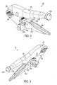
- Figures 5 and 6 depict side views of the locking pliers 360 as assembled.
- Figure 5 illustrates the locking pliers 360 where the pivot latch 390 is in the unlocked position, such that the linkage bar 385 may freely move into and out of the overcenter position.
- pivot latch bar 460 (obscured in Figure 5 ) is positioned to be out of the plane of the alignment between the lower handle latch receptacles 450 and the corresponding linkage latch receptacle 440 (also obscured in Figure 5 ) in the linkage bar 385, so that the linkage bar 385 may move between the overcenter, top dead center, and relaxed jaw-opening positions.
- Figure 6 depicts the pivot latch 390 in the locked position, such that the pivot latch bar 460 is positioned in the plane of alignment between the lower handle latch receptacles 450 and the corresponding linkage latch receptacle 440, preventing the linkage bar 385 from moving relative to the lower handle 370, and thus holding the linkage bar 385 in the overcenter locked position.
- the locking pliers 10, the locking pliers 360, variations thereof, or other such embodiments may each be of any suitable construction or configuration, including but not limited to being formed from metal, plastic, elastomer, wood or combinations thereof.
- the handles i.e. the upper handle 20 and/or the lower handles 100 or 370
- a grip material including but not limited to rubber.
- linkage latch 290 and the pivot latch 390 are configured to couple the linkage bars 145 or 385 to the lower handles 100 or 370
- the linkage latch 290, the pivot latch 390, variations thereof, or other such embodiments may be configured to couple the linkages to the upper handle 20, the lower jaw 70, the upper jaw 50, or any other appropriate location of the locking pliers, so as to selectively prevent movement of the linkage from the overcenter lock position.
Landscapes
- Engineering & Computer Science (AREA)
- Mechanical Engineering (AREA)
- Gripping Jigs, Holding Jigs, And Positioning Jigs (AREA)
- Hand Tools For Fitting Together And Separating, Or Other Hand Tools (AREA)
Description
- The present invention relates generally to pliers having an overcenter locking position.
- Locking pliers generally rely on an "overcenter" linkage to lock the pliers into a position compressing jaws thereof against a work piece. It may be appreciated, however, that bumping or otherwise unintentionally disturbing such pliers in such an overcenter locked position may cause the pliers to spring open and disengage from the work piece.
-
US 2003/0019045 discloses a multi hand tool comprising a first jaw and a second jaw. The first and second jaws having convex outer surfaces. The multi tool comprises first and second handles having a pair of spaced upstanding side wills and a base connecting the sides together. A locking mechanism is provided which has a linkage connection which connects the second handle with the first handle. -
WO 92/03260 -
US 4,889,021 discloses clamping pliers with locking means. The pliers have a threaded adjustment screw and an associated padlock having a long U-shaped shackle. -
US 2006/0248990 discloses a rescue tool for carrying a roof or sheet goods. A pair of clamping arms are joined together by a pivot pin, a helical spring and a quick release mechanism. A security strap is attached to the handle with a length that is sufficient to be wrapped around the lower handle and secure the handles in the closed position. - Among other things, the present application relates to preventing pliers from unintentionally moving from an overcenter locked position.
- According to one aspect of this disclosure, there is provide a pair of pliers according to claim 1
- Preferably the upper handle is separately formed from and attached to the upper jaw.
- Preferably the upper handle is integrally formed with the upper jaw.
- Preferably the lower jaw and the linkage are configured to pivot about respective pivot axes in the upper handle.
- Preferably the lock member is movable into and out of engagement with the linkage in a direction perpendicular to a direction of movement of the linkage.
- Preferably the lock member is received in one or more holes extending through the lower handle.
- Preferably the linkage contains a lock receiving recess having a larger sized recess portion and a smaller sized recess portion, the smaller sized recess portion extending through one side of the linkage.
- Preferably when the lock member comprises a larger sized lock portion and a smaller sized lock portion, the larger sized lock portion is sized to be received in the larger sized recess portion but not the smaller sized recess portion, and the smaller sized lock portion is sized to be received in both the larger sized recess portion and the smaller sized recess portion.
- Preferably when in the locking configuration, the lock member is positioned such that the larger sized lock portion is received in the larger sized recess region, wherein when in the release configuration, the lock member is positioned such that the smaller sized lock portion is received in the larger sized recess region, but may pass through the smaller sized recess region to permit movement of the linkage.
- Preferably the lock member comprises a generally cylindrical shape that is slidable relative to the linkage and the lower handle across a direction of motion for the linkage, such that either the larger sized lock portion or the smaller sized lock portion may selectively be positioned within the linkage.
- Preferably a snap ring is coupled to the lock member, the snap ring configured to provide a tactile indication of movement between the locking configuration and the release configuration.
- Preferably the linkage and the lower handle contain associated lock member recesses, wherein when the lock member is in the locking configuration, a portion of the lock member extends through the lock member recesses of the linkage and the lower handle.
- Preferably the lock member is rotatable between the locking configuration and the release configuration.
- Preferably a latch handle is coupled to the lock member and configured to facilitate rotation of the lock member between the locking configuration and the release configuration.
- Preferably the portion of lock member extendable through the lock member recesses of the linkage and the lower handle comprises a bar coupled to the handle, rotatable into and out of the lock member recesses through manipulation of the latch handle.
- Preferably the lock member is coupled to the linkage at a pivot axis of the linkage.
- Preferably an adjustment knob is configured to move a pivot axis associated with the linkage relative to the upper jaw.
- Preferably a release lever is configured to move the linkage from the jaw-closing position.
- Preferably the release lever is coupled to the lower handle.
- Preferably the linkage comprises a spring coupled to the lower jaw and the upper structure, configured to bias the lower jaw into a position spaced from the upper jaw in the jaw-opening position.
- Preferably the lower handle comprises a U-shaped cross section configured to receive the linkage therein.
- These and other objects, features, and characteristics of the present invention, as well as the methods of operation and functions of the related elements of structure and the combination of parts and economies of manufacture, will become more apparent upon consideration of the following description and the appended claims with reference to the accompanying drawings, all of which form a part of this specification, wherein like reference numerals designate corresponding parts in the various figures. In one embodiment of the invention, the structural components illustrated herein are drawn to scale. It is to be expressly understood, however, that the drawings are for the purpose of illustration and description only and are not a limitation of the invention. In addition, it should be appreciated that structural features shown or described in any one embodiment herein can be used in other embodiments as well. It is to be expressly understood, however, that the drawings are for the purpose of illustration and description only and are not intended as a definition of the limits of the invention. As used in the specification and in the claims, the singular form of "a", "an", and "the" include plural referents unless the context clearly dictates otherwise.
- Features of the pliers in accordance with one embodiment are shown in the drawings, in which like reference numerals designate like elements. The drawings form part of this original disclosure in which:
-
Figure 1 is an exploded view of an embodiment of the locking pliers of the present invention, showing the constituent components thereof; -
Figure 2 is a perspective view of the embodiment ofFigure 1 , showing the locking pliers in an unlocked position, whereby the locking pliers may move into and out of an overcenter locked position; -
Figure 3 is another perspective view of the embodiment ofFigure 1 , showing the locking pliers in a locked position, whereby the locking pliers are prevented from moving out of the overcenter locked position; -
Figure 4 is an exploded view of another embodiment of the locking pliers of the present invention, showing the constituent components thereof; -
Figure 5 is a side view of the embodiment ofFigure 4 , showing the locking pliers in an unlocked position, whereby the locking pliers may move into and out of an overcenter locked position; and -
Figure 6 is another side view of the embodiment ofFigure 4 , showing the locking pliers in a locked position, whereby the locking pliers are prevented from moving out of the overcenter locked position. -
Figure 1 illustrates an exploded view of an embodiment of a pair oflocking pliers 10 of the present invention, wherein components thereof may be seen. Thelocking pliers 10 comprise anupper handle 20 that is elongated between afirst end 30 and asecond end 40. Received in thefirst end 30 is anupper jaw 50 of thelocking pliers 10, forming an upper structure. As shown in the illustrated embodiment, theupper jaw 50 may be slidably received into thefirst end 30, and may be secured thereto by any appropriate manner, including but not limited to being welded, glued, removably or non-removably attached by one or more mechanical fasteners, or so on. In some embodiments, theupper jaw 50 may be integrally formed at thefirst end 30 of theupper handle 20. - Pivotally coupled to the
handle 20 by afirst pivot pin 60 is alower jaw 70. As shown in the illustrated embodiment, afirst pivot hole 80 of thelower jaw 70 is configured to be received in theupper handle 20, and align with corresponding upperhandle pivot holes 90. The upperhandle pivot holes 90 extend through the upper handle 20 (or otherwise formed on opposing faces of the upper handle 20) and have a receiving space therebetween to receive a portion of thelower jaw 70, such that thefirst pivot pin 60 passes through both the upperhandle pivot holes 90 and thefirst pivot hole 80, holding thelower jaw 70 within the space between the upperhandle pivot holes 90 by thefirst pivot pin 60. Thelower jaw 70 is therefore able to pivot on thefirst pivot pin 60 relative to theupper handle 20 and theupper jaw 50. In various embodiments, thefirst pivot pin 60 may be configured as a screw, a bolt, a rivet, or any other appropriate body configured to pivotally secure thelower jaw 70 to theupper handle 20. It may be appreciated, then, that thelower jaw 70 may pivot with respect to theupper jaw 50, to open and close the jaws of thelocking pliers 10. - Also pivotally coupled to the
lower jaw 70 is alower handle 100, which is elongated, to extend generally parallel to but below theupper handle 20. Thelower jaw 70 and thelower handle 100 together form a lower structure. As shown, thelower handle 100 includes therein first lowerhandle pivot holes 110, that extend through thelower handle 100, and are configured to receive a portion of thelower jaw 70 therebetween. Specifically, thelower handle 100 is configured to receive a portion of thelower jaw 70 that contains asecond pivot hole 120 formed therein. Asecond pivot pin 130 is received by both the first lowerhandle pivot holes 110 and thesecond pivot hole 120 of thelower jaw 70, to pivotally couple thelower handle 100 and thelower jaw 70. In various embodiments, thesecond pivot pin 130 may be configured as a screw, a bolt, a rivet, or any other appropriate body configured to pivotally secure thelower jaw 70 to thelower handle 100. - An
overcenter linkage 140 operatively connects between the upper structure and the lower structure. Specifically, the linkage includes alinkage bar 145, which is configured to move into and out of an overcenter jaw-closing position, described in greater detail below. As shown, thelinkage bar 145 contains therein anupper linkage pivot 150, which is configured to be pivotally coupled to a receiving region in theupper handle 20. While in some embodiments theupper linkage pivot 150 may engage an axle defining a pivot axis in the receiving region, in other embodiments theupper linkage pivot 150 may comprise a curved shape on thelinkage bar 145, where the curved shape generally surrounds a pivot axis. A lowerlinkage pivot hole 160 of thelinkage bar 145 is configured to be received by thelower handle 100. In the illustrated embodiment, thelower handle 100 includes second lowerhandle pivot holes 170, surrounding a region in which the lowerlinkage pivot hole 160 is inserted into, so that the second lowerhandle pivot holes 170 are aligned with the lowerlinkage pivot hole 160. As such, in some embodiments thelower handle 100 may have a generally U-shaped cross section. Athird pivot pin 180 may therefore be inserted through both the second lowerhandle pivot holes 170 and the lowerlinkage pivot hole 160, such that thelinkage bar 145 couples thelower handle 100 to theupper handle 20, and may push or pull on the assembly of thelower handle 100 and thelower jaw 70 to move the lockingpliers 10 into and out of a relaxed jaw-opening position, a top-dead-center position, and the overcenter jaw-closing position, as described in greater detail below. - Further coupling the
lower jaw 70 and theupper handle 20 as part of thelinkage 140 may be aspring 190 having afirst end 200 that is received in a receivingaperture 210 of thelower jaw 70, and asecond end 220 that is received in the upper handle. As discussed in greater detail below, thespring 190 is configured to pull thelower jaw 70 open, which would generally bias thelinkage bar 145 into the relaxed jaw-opening position. When the linkage bar 145moves into the jaw-closing position, however, the lowerlinkage pivot hole 160 is positioned to the interior of thesecond pivot hole 120 and the upper linkage pivot 150 (i.e. proximal to theupper handle 20, resulting in any force applied between theupper jaw 50 and thelower jaw 70 act to drive the lowerlinkage pivot hole 160 further inward towards theupper handle 20, instead of causing thelower jaw 70 to open from theupper jaw 50, effectively locking the jaws around a work piece therebetween. As such, it may be appreciated that if the lockingpliers 10 are bumped when in the overcenter jaw-closing position, the linkage may move from overcenter to top-dead-center (where the lowerlinkage pivot hole 160 is in alignment across thelinkage bar 145 with thesecond pivot hole 120 and the upper linkage pivot 150), at which point thespring 190 may cause the linkage to spring into the relaxed jaw-opening position, opening thelower jaw 70 from theupper jaw 50, and releasing the work piece. - It may be appreciated that the positioning of the
linkage bar 145 may be modified by anadjustment knob 230, which may be received in thehandle 20, and configured to modify the position of theupper linkage pivot 150 relative to thehandle 20. In the illustrated embodiment, theadjustment knob 230 is a turn-screw knob that extends from thesecond end 40 of thehousing 20, and may screw into and out of thehousing 20 to move a pivot axis of thelinkage bar 145 in thehandle 20 either closer to or further from theupper jaw 50. As such, theadjustment knob 230 may modify the angle of thelinkage bar 145, to allow thelower jaw 70 and theupper jaw 50 to clamp down onto different sizes of work pieces, and with different amounts of force. - The pivotal coupling of the
upper handle 20,lower jaw 70,lower handle 100, andlinkage bar 145, as well as the coupling of thespring 190 therebetween, may generally allow the lockingpliers 10 to operate through the squeezing of thelower handle 100 towards theupper handle 20. As thelower handle 100 is squeezed with a work piece between theupper jaw 50 andlower jaw 70, thelinkage bar 145 may pivot to the top-dead-center position. As thelower handle 100 is squeezed further, thelinkage bar 145 may move to the overcenter jaw-closing position, causing the lockingpliers 10 to remain clamped onto the work piece. To provide a mechanical advantage to move thelinkage bar 145 back to the top-dead-center or the relaxed jaw-opening positions, and thus release the work piece, arelease lever 240 is pivotally coupled to thelower handle 100. As shown inFigure 1 , a releaselever pivot pin 250 may be inserted through third lowerhandle pivot holes 260 formed in thelower handle 100, and through a corresponding releaselever pivot hole 270 formed in therelease lever 240. By lifting therelease lever 240 towards thelinkage bar 145, afulcrum point 280 formed in therelease lever 240 may press against thelinkage bar 145 with sufficient force to bring thelinkage bar 145 back out of the overcenter jaw-closing position, and back into the top-dead-center or relaxed jaw-opening positions, releasing thelower jaw 70. - As indicated above, it may be appreciated that the
release spring 190 may be configured to promote the release of thelower jaw 70 and thelinkage bar 145 from being locked in the overcenter jaw-closing position. As such, when the lockingpliers 10 are locked around a work piece in the overcenterjaw-closing position, bumping or otherwise disturbing the lockingpliers 10 may result in thelinkage bar 145 slipping out of the overcenter jaw-closing position, leading to thelower jaw 70 opening away from theupper jaw 50. In such a situation, any work piece located between thelower jaw 70 and theupper jaw 50 may be inadvertently released. Additionally, the force of thespring 190 may cause the lockingpliers 10 to spring away from the work piece and subsequently fall from where the lockingpliers 10 were positioned. Such unintentional unlocking of the lockingpliers 10 may also occur where a user of the lockingpliers 10 accidently pulls on therelease lever 240, moving thelinkage bar 145 out of the overcenter locked position. As described in greater detail below, preventing such unintentional movements of thelinkage bar 145 are an object of the present disclosure. - As shown in the exploded view of
Figure 1 , alinkage latch 290 may be configured to lock the angle of thelinkage bar 145 in place, so that thelinkage bar 145 may not move out of the overcenter jaw-closing position, back into the top-dead-center or the relaxed jaw-opening positions. In the illustrated embodiment, thelinkage latch 290 is configured to engage alatch receptacle 300 in thelinkage bar 145. Specifically in the illustrated embodiment, thelinkage latch 290 is generally formed as a cylinder having both asmaller diameter region 310 and alarger diameter region 320. Thelinkage latch 290 is configured to extend through a pair of latch holes 330 formed in thelower handle 100 that are positioned to be in alignment with thelatch receptacle 300 when thelinkage bar 145 is in the overcenter jaw-closing position. As shown in the illustrated embodiment, thelatch receptacle 300 may be formed as having a cross-sectional shape of a generally enclosed circle extending through thelinkage bar 145, with aside opening 340 extending to one side of thelinkage bar 145. With such a configuration, thelinkage latch 290 may slidably be positioned such that either thelarger diameter region 320 or thesmaller diameter region 310 is within the generally enclosed circular cross-sectional shape of thelatch receptacle 300. When thelarger diameter region 320 is positioned in thelatch receptacle 300, thelinkage bar 145 surrounds thelarger diameter region 320, which is unable to pass through theside opening 340, preventing thelinkage bar 145 from moving out of the overcenter locked position due to the engagement between thelinkage latch 290 and thelatch receptacle 300. Alternatively, where thelinkage latch 290 is positioned such that thesmaller diameter region 310 is generally surrounded by thelatch receptacle 300, thelinkage bar 145 may freely move from the overcenter jaw-closing position, as thesmaller diameter region 310 may pass through theside opening 340 as thelinkage bar 145 moves into and out of the overcenter jaw-closing position. Further shown inFigure 1 is asnap ring 350 that may be received on thelinkage latch 290, so as to provide a tactile sensation as thelinkage latch 290 is moved between a locked position (where thelarger diameter region 320 is positioned in the latch receptacle 300), and an unlocked position (where thesmaller diameter region 310 is positioned in the latch receptacle 300). -
Figures 2 and 3 depict perspective views of the lockingpliers 10 as assembled. Specifically,Figure 2 illustrates the lockingpliers 10 where thelinkage latch 290 is in the unlocked position, such that thelinkage bar 145 may freely move into and out of the overcenter position. Accordingly, the smaller diameter region 310 (obscured inFigure 2 ) is positioned to be in the plane of movement of theside opening 340 as thelinkage bar 145 moves between the overcenter, top dead center, and relaxed jaw-opening positions. Thelarger diameter region 320 thus protrudes from thelower handle 100 when the locking pliers are not latched. As shown inFigure 3 , however, when thelinkage latch 290 is in the locked position, thesmaller diameter region 310 may extend from thelower handle 100, while the larger diameter region 320 (obscured inFigure 3 ) positioned to be within thelatch receptacle 300, preventing thelinkage bar 145 from moving out of the overcenter locked position by being too large to pass through theside opening 340 when thelinkage bar 145 attempts to move, holding thelinkage bar 145 in place. - It may be appreciated that other mechanisms for preventing movement of a linkage from the overcenter locked position are also possible, and may be utilized in other embodiments. For example,
Figure 4 depicts an exploded view of a pair of lockingpliers 360 that includes alower handle 370 and alinkage 380 with alinkage bar 385, which may be locked in place relative to one another by apivot latch 390, as described in greater detail below. Other components of the lockingpliers 360 may be similar to corresponding components of the lockingpliers 10, and as such, are labeled identically to those components of the lockingpliers 10 depicted inFigure 1 . For example, the lockingpliers 360 include theupper handle 20 having thefirst end 30 and thesecond end 40. Theupper jaw 50 is received in thefirst end 30, while theadjustment knob 230 is received in thesecond end 40. The lockingpliers 360 also includes thelower jaw 70, pivotally coupled to theupper handle 20 by thefirst pivot pin 60, that extends through the upperhandle pivot holes 90 of theupper handle 20 and thefirst pivot hole 80 of thelower jaw 70. Additionally, thespring 190 is coupled to theupper handle 20 and thelower jaw 70, with thefirst end 200 being received in the receivingaperture 210 of thelower jaw 70, and thesecond end 220 being received in theupper handle 20. - As shown, the
lower handle 370 of the lockingpliers 360 is pivotally coupled to thelower jaw 70. In particular, thelower jaw 70 is received within thelower handle 370 with first lowerhandle pivot holes 400 of thelower handle 370 aligned with thesecond pivot hole 120 of thelower jaw 70, so that thesecond pivot pin 130 may be inserted therethrough to pivotally couple thelower jaw 70 to thelower handle 370. Thelinkage bar 385 contains an associated lowerlinkage pivot hole 410, which is received between second lower handle pivot holds 420 of thelower handle 370. Additionally, pivot latch holes 430 of thepivot latch 390 may also be aligned with the lowerlinkage pivot hole 410 and the second lowerhandle pivot holes 420, so that thethird pivot pin 180 may be inserted therethrough, pivotally coupling thelower handle 370, thelinkage bar 385, and thepivot latch 390 together. With such an alignment, thepivot latch 390 may rotate about thepivot pin 180, and as such may be selectively positioned to engage both a linkage latch receptacle 440 in thepivot latch 390 and lowerhandle latch receptacles 450 in thelower handle 370, which would lock thelinkage bar 385 to thelower handle 370, preventing movement of thelinkage bar 385 from the overcenter locked position. Specifically, apivot latch bar 460 extending betweenpivot latch flanges 470 containing the pivot latch holes 430 may rotate into the aligned linkage latch receptacle 440 and lowerhandle latch receptacles 450 when thelinkage bar 385 is in the overcenter locked position, thus preventing pivotal motion between thelinkage bar 385 and thelower handle 370 to move thelinkage bar 385 out of the overcenter locked position. In an embodiment, such movement of thepivot latch 390 may be effectuated by manipulation ofhandles 475 extending from thepivot latch flanges 470 for engagement by a finger of a user of the lockingpliers 360. To allow the lockingpliers 360 to be subsequently unlocked, thepivot latch 390 may be rotated so that thepivot latch bar 460 disengage from the lowerhandle latch receptacles 450 and the linkage latch receptacle 440, disconnecting the connection between thelinkage bar 385 and thelower handle 370. In the illustrated embodiment, thepivot latch bar 460 is configured to be received in a secondlinkage latch receptacle 480 when thepivot latch 390 is rotated so as to not interfere with the pivotal motion of thelinkage bar 385. - Because the locking
pliers 360 has an increased number of pivoting or otherwise rotating members about thethird pivot pin 180, in the illustrated embodiment awasher 490 is additionally provided to distribute the load on thethird pivot pin 180, reduce wear, or otherwise act as a spacer. It may be appreciated, however, that washers such as thewasher 490 are optional, and may be found associated with the other pivot pins, or may be omitted, across various embodiments. In various embodiments, other elements of thelinkage bar 385 and thelower handle 370 may generally resemble and function in a manner similar to corresponding elements of the lockingpliers 10. For example, thelinkage bar 385 includes anupper linkage pivot 500 which similarly toupper linkage pivot 150 would be received in theupper handle 20 at a position that is modifiable by theadjustment knob 230. Additionally, thelower handle 370 includes third lowerhandle pivot holes 510 that may be aligned with the releaselever pivot hole 270 of therelease lever 240 so that the releaselever pivot pin 250 may be inserted therethrough to pivotally couple therelease lever 240 to thelower handle 370. As shown in the embodiment ofFigure 4 , however, in some embodiments thelinkage bar 385 may include a releaselever receiving region 520 configured to enhance the mechanical advantage provided by thefulcrum point 280 of therelease lever 240 as it engages thelinkage bar 385 to move thelinkage bar 385 out over the overcenter locked position. -
Figures 5 and 6 depict side views of the lockingpliers 360 as assembled. Specifically,Figure 5 illustrates the lockingpliers 360 where thepivot latch 390 is in the unlocked position, such that thelinkage bar 385 may freely move into and out of the overcenter position. Accordingly, pivot latch bar 460 (obscured inFigure 5 ) is positioned to be out of the plane of the alignment between the lowerhandle latch receptacles 450 and the corresponding linkage latch receptacle 440 (also obscured inFigure 5 ) in thelinkage bar 385, so that thelinkage bar 385 may move between the overcenter, top dead center, and relaxed jaw-opening positions. Alternatively,Figure 6 depicts thepivot latch 390 in the locked position, such that thepivot latch bar 460 is positioned in the plane of alignment between the lowerhandle latch receptacles 450 and the corresponding linkage latch receptacle 440, preventing thelinkage bar 385 from moving relative to thelower handle 370, and thus holding thelinkage bar 385 in the overcenter locked position. - Various components of the locking
pliers 10, the lockingpliers 360, variations thereof, or other such embodiments may each be of any suitable construction or configuration, including but not limited to being formed from metal, plastic, elastomer, wood or combinations thereof. In some embodiments, the handles (i.e. theupper handle 20 and/or thelower handles 100 or 370) may be at least partially wrapped in a grip material, including but not limited to rubber. Additionally, while in the illustrated embodiment thelinkage latch 290 and thepivot latch 390 are configured to couple the linkage bars 145 or 385 to thelower handles linkage latch 290, thepivot latch 390, variations thereof, or other such embodiments may be configured to couple the linkages to theupper handle 20, thelower jaw 70, theupper jaw 50, or any other appropriate location of the locking pliers, so as to selectively prevent movement of the linkage from the overcenter lock position. - Although the invention has been described in detail for the purpose of illustration based on what is currently considered to be the most practical and preferred embodiments, it is to be understood that such detail is solely for that purpose and that the invention is not limited to the disclosed embodiments, but, on the contrary, is intended to cover modifications and equivalent arrangements that are within the scope of the appended claims. For example, it is to be understood that the present invention contemplates that, to the extent possible, one or more features of any embodiment can be combined with one or more features of any other embodiment.
Claims (14)
- A pair of pliers comprising:an upper structure including an upper jaw (50) and an upper handle (20) extending from the upper jaw (50);a lower structure including a lower jaw (70) and a lower handle (100), the lower jaw (70) being configured to pivot relative to the upper jaw (50), and the lower handle (100) being configured to pivot relative to the lower jaw (70);an overcenter linkage (140) operatively connected between the upper structure and the lower structure, the linkage (140) biasing the lower handle (100) and the lower jaw (70) away from the upper handle (20) and the upper jaw (50), respectively, when in a jaw-opening position, and enabling the lower jaw (70) and the lower handle (100) to be retained in a closed configuration when the linkage (140) is in a jaw-closing position; anda lock member (290, 390) movable between a locking configuration and a release configuration, wherein when the lock member (290, 390) is in the locking configuration it prevents pivoting movement of the lower handle (100) from the closed configuration and retains the jaws (50, 70) in a closed position, and wherein when the lock member (290, 390) is in the release configuration, it enables the lower handle (100) to be moved away from the closed configuration and allows the jaws (50, 70) to move to an open position, characterized in that when the lock member (290, 390) is in the locking configuration, it fixedly attaches the linkage (140) to the lower handle (100).
- The pliers of claim 1, wherein the upper handle (20) is separately formed from and attached to the upper jaw (50), or alternatively the upper handle (20) is integrally formed with the upper jaw (50).
- The pliers of claims 1 or 2, wherein the lower jaw (70) and the linkage (140) are configured to pivot about respective pivot axes in the upper handle (20).
- The pliers of claims 1 to 3, wherein the lock member (290) is movable into and out of engagement with the linkage (140) in a direction perpendicular to a direction of movement of the linkage (140).
- The pliers of claims 1 to 4, wherein the lock member (290) is received in one or more holes (330) extending through the lower handle (100).
- The pliers of claims 1 to 5, wherein the linkage (140) contains a lock receiving recess (300) having a larger sized recess portion and a smaller sized recess portion (340), the smaller sized recess portion (340) extending through one side of the linkage.
- The pliers of claim 6, wherein when the lock member (290) comprises a larger sized lock portion (320) and a smaller sized lock portion (310), the larger sized lock portion (320) being sized to be received in the larger sized recess portion (300) but not the smaller sized recess portion (340), and the smaller sized lock portion (310) being sized to be received in both the larger sized recess portion (300) and the smaller sized recess portion (340).
- The pliers of claim 7, wherein when in the locking configuration, the lock member (290) is positioned such that the larger sized lock portion (320) is received in the larger sized recess region (300), wherein when in the release configuration, the lock member (290) is positioned such that the smaller sized lock portion (310) is received in the larger sized recess region (300), but may pass through the smaller sized recess region (340) to permit movement of the linkage (140).
- The pliers of claims 7 or 8, wherein the lock member (290) comprises a generally cylindrical shape that is slidable relative to the linkage (140) and the lower handle (100) across a direction of motion for the linkage (140), such that either the larger sized lock portion (320) or the smaller sized lock portion (310) may selectively be positioned within the linkage (140).
- The pliers of claims 1 to 9, further comprising a snap ring (350) coupled to the lock member (290), the snap ring (350) configured to provide a tactile indication of movement between the locking configuration and the release configuration.
- The pliers of claims 1 to 10, wherein the linkage (140) and the lower handle (100) contain associated lock member recesses, wherein when the lock member (290) is in the locking configuration, a portion of the lock member (290) extends through the lock member recesses of the linkage (140) and the lower handle (100).
- The pliers of claims 1 to 11, wherein a latch handle is coupled to the lock member (390) and configured to facilitate rotation of the lock member (390) between the locking configuration and the release configuration.
- The pliers of claim 12, wherein the portion of lock member (290) extendable through the lock member recesses of the linkage (140) and the lower handle (100, 370) comprises a bar (145, 385) coupled to the handle (370), rotatable into and out of the lock member recesses through manipulation of the latch handle.
- The pliers of claims 1 to 13, wherein the lock member (390) is coupled to the linkage at a pivot axis of the linkage (140).
Applications Claiming Priority (1)
| Application Number | Priority Date | Filing Date | Title |
|---|---|---|---|
| US13/360,506 US9027447B2 (en) | 2012-01-27 | 2012-01-27 | Locking pliers with handle locking mechanism |
Publications (2)
| Publication Number | Publication Date |
|---|---|
| EP2620258A1 EP2620258A1 (en) | 2013-07-31 |
| EP2620258B1 true EP2620258B1 (en) | 2014-11-19 |
Family
ID=47715852
Family Applications (1)
| Application Number | Title | Priority Date | Filing Date |
|---|---|---|---|
| EP20130152679 Active EP2620258B1 (en) | 2012-01-27 | 2013-01-25 | Locking pliers with handle locking mechanism |
Country Status (6)
| Country | Link |
|---|---|
| US (1) | US9027447B2 (en) |
| EP (1) | EP2620258B1 (en) |
| AU (1) | AU2013200295B2 (en) |
| BR (1) | BR202013003496U2 (en) |
| CA (1) | CA2802259C (en) |
| MX (1) | MX2013001089A (en) |
Cited By (2)
| Publication number | Priority date | Publication date | Assignee | Title |
|---|---|---|---|---|
| TWI794467B (en) * | 2018-04-11 | 2023-03-01 | 德商韋扎格有限責任兩合公司 | Crimping tool |
| TWI809162B (en) * | 2018-08-23 | 2023-07-21 | 德商韋扎格有限責任兩合公司 | Press- oder crimpzange |
Families Citing this family (19)
| Publication number | Priority date | Publication date | Assignee | Title |
|---|---|---|---|---|
| CN105269477A (en) * | 2014-07-24 | 2016-01-27 | 吴明杰 | Clamping device capable of rapidly adjusting clamping force |
| USD771456S1 (en) | 2014-08-01 | 2016-11-15 | Milwaukee Electric Tool Corporation | Pliers with control key |
| USD755603S1 (en) * | 2014-09-08 | 2016-05-10 | Irwin Industrial Tool Company | Multi-tool |
| US20160207175A1 (en) | 2015-01-15 | 2016-07-21 | Milwaukee Electric Tool Corporation | Locking pliers with improved adjustment member |
| USD782891S1 (en) | 2015-04-02 | 2017-04-04 | Milwaukee Electric Tool Corporation | Locking pliers |
| USD803021S1 (en) * | 2015-07-30 | 2017-11-21 | Ming Chieh Wu | Pliers |
| TWI581923B (en) * | 2015-10-13 | 2017-05-11 | Sullstar Technologies Inc | Clamp tool and its stop mechanism |
| TWI556921B (en) * | 2015-12-25 | 2016-11-11 | Li Tu Wu | Universal pliers security structure |
| US20170203413A1 (en) * | 2016-01-18 | 2017-07-20 | Li-Tu Wu | Safety structure for pliers |
| US20170203414A1 (en) * | 2016-01-18 | 2017-07-20 | Li-Tu Wu | Switching structure for pliers |
| US11541514B2 (en) | 2016-03-23 | 2023-01-03 | Milwaukee Electric Tool Corporation | Locking pliers |
| US20180009086A1 (en) * | 2016-07-07 | 2018-01-11 | Gong Maw Enterprise Co., Ltd. | Self-locking pliers |
| USD804922S1 (en) * | 2016-11-30 | 2017-12-12 | Harry Wong | Big mouth pliers |
| USD863933S1 (en) * | 2017-06-28 | 2019-10-22 | Harley-Davidson Motor Company Group, LLC | Latch handle |
| CN111051004B (en) | 2017-09-11 | 2022-07-22 | 米沃奇电动工具公司 | Locking pliers with movable torque-increasing jaw section |
| US10504495B1 (en) | 2018-07-06 | 2019-12-10 | Daniel Pawlovich | Kick drum pedal clamp mechanism |
| USD910395S1 (en) | 2019-03-11 | 2021-02-16 | Milwaukee Electric Tool Corporation | Pliers |
| TWI730670B (en) * | 2020-03-13 | 2021-06-11 | 新祐工業有限公司 | Labor-saving pliers |
| TWI730669B (en) * | 2020-03-13 | 2021-06-11 | 新祐工業有限公司 | Multifunctional pliers |
Family Cites Families (24)
| Publication number | Priority date | Publication date | Assignee | Title |
|---|---|---|---|---|
| US2532659A (en) * | 1948-06-01 | 1950-12-05 | Burns Bruce | Snap-lock wrench |
| US2539865A (en) | 1949-08-24 | 1951-01-30 | Sarvie Walter | Actuating and locking means for the handles of plier type tools |
| US2643567A (en) * | 1951-09-28 | 1953-06-30 | Johnson John | Toggle actuated plier wrench |
| US2853910A (en) | 1956-11-30 | 1958-09-30 | Petersen William | Latch means for plier type toggle wrench |
| US4889022A (en) * | 1988-03-11 | 1989-12-26 | Peviani Thomas P | Quick releasable vice-grip pliers |
| US4889021A (en) | 1989-01-06 | 1989-12-26 | Morrison Joseph L | Clamping plier with locking means |
| US5014578A (en) * | 1990-01-08 | 1991-05-14 | Flentge Melvin L | Pipe tongs |
| CA2090112A1 (en) * | 1990-08-23 | 1992-02-24 | J. David Mills | Locking wrenches |
| US5052251A (en) * | 1990-08-23 | 1991-10-01 | Blue Water Holding Company, Inc. | Locking wrenches |
| US5233893A (en) * | 1990-11-30 | 1993-08-10 | Schmidt Marion E | Safety plier type toggle wrench |
| FR2736572B1 (en) * | 1995-07-13 | 1997-10-03 | Facom | PLIERS |
| US6199458B1 (en) | 1997-05-27 | 2001-03-13 | Emerson Electric Co. | Locking pliers |
| US6279431B1 (en) | 1999-06-15 | 2001-08-28 | Brett P. Seber | Self-adjusting pliers |
| US6626070B2 (en) | 2001-05-04 | 2003-09-30 | Irwin Industrial Tool Company | Compound toggle link retention mechanism |
| US20030019045A1 (en) | 2001-07-30 | 2003-01-30 | Great Neck Saw Manufacturers, Inc. | Multi hand tool |
| US6941844B2 (en) | 2003-11-10 | 2005-09-13 | Jeffrey B. Hile | Self-adjusting locking pliers |
| US7146887B2 (en) | 2005-02-07 | 2006-12-12 | Robert Evan Hunter | Automatic sizing one-handed locking pliers |
| US20060248990A1 (en) | 2005-05-04 | 2006-11-09 | Todd Bertholf | Rescue tool for carrying a roof or sheet goods |
| US20070209484A1 (en) | 2006-03-13 | 2007-09-13 | Chervenak Thomas M | Locking pliers |
| US20080060486A1 (en) | 2006-09-11 | 2008-03-13 | Thomas Michael Robert | Locking pliers for controlled manipulation of loads |
| WO2008137927A1 (en) | 2007-05-07 | 2008-11-13 | Penn United Technologies, Inc. | Locking pliers with cam |
| US8225700B2 (en) | 2009-01-26 | 2012-07-24 | Hile Jeffrey B | Locking pliers with quick jaw release |
| US8776646B2 (en) * | 2010-02-23 | 2014-07-15 | Irwin Industrial Tool Company | Locking pliers |
| US20120096995A1 (en) * | 2010-10-22 | 2012-04-26 | Shin-An Shih | Self-adjusting locking pliers with rear retainer |
-
2012
- 2012-01-27 US US13/360,506 patent/US9027447B2/en active Active
-
2013
- 2013-01-10 CA CA2802259A patent/CA2802259C/en not_active Expired - Fee Related
- 2013-01-21 AU AU2013200295A patent/AU2013200295B2/en not_active Ceased
- 2013-01-25 MX MX2013001089A patent/MX2013001089A/en not_active Application Discontinuation
- 2013-01-25 EP EP20130152679 patent/EP2620258B1/en active Active
- 2013-01-29 BR BRBR202013003496-2U patent/BR202013003496U2/en not_active Application Discontinuation
Cited By (2)
| Publication number | Priority date | Publication date | Assignee | Title |
|---|---|---|---|---|
| TWI794467B (en) * | 2018-04-11 | 2023-03-01 | 德商韋扎格有限責任兩合公司 | Crimping tool |
| TWI809162B (en) * | 2018-08-23 | 2023-07-21 | 德商韋扎格有限責任兩合公司 | Press- oder crimpzange |
Also Published As
| Publication number | Publication date |
|---|---|
| US9027447B2 (en) | 2015-05-12 |
| CA2802259C (en) | 2017-09-19 |
| AU2013200295B2 (en) | 2017-12-14 |
| MX2013001089A (en) | 2013-07-26 |
| AU2013200295A1 (en) | 2013-08-15 |
| CA2802259A1 (en) | 2013-07-27 |
| BR202013003496U2 (en) | 2015-07-07 |
| US20130192429A1 (en) | 2013-08-01 |
| EP2620258A1 (en) | 2013-07-31 |
Similar Documents
| Publication | Publication Date | Title |
|---|---|---|
| EP2620258B1 (en) | Locking pliers with handle locking mechanism | |
| US9844857B2 (en) | Locking pliers with handle locking mechanism | |
| US8123205B2 (en) | Universal locking mechanism for a clamp | |
| US8827225B2 (en) | Suspension device | |
| US9346178B2 (en) | Snips operable by a single hand | |
| CA1096421A (en) | Lifting clamp | |
| US8776646B2 (en) | Locking pliers | |
| EP1591204B1 (en) | Hand actuable locking clamp | |
| US8079150B2 (en) | Garden shears | |
| US7946039B2 (en) | Hand-held ratchet tool for moving a pair of jaw members toward and away from each other | |
| US7669505B2 (en) | Pin lock pliers | |
| US20090007733A1 (en) | Clamping and cutting apparatus with adjustable head | |
| EP2243598B1 (en) | Ratcheting adjustable wrench | |
| US8444020B1 (en) | Assembly for hand held or remote elevated operation of aerosol spray cans | |
| US5033338A (en) | Self-locking device | |
| EP3064322A1 (en) | Clamping device with removable handles | |
| EP3277901B1 (en) | Latch having tool recess in trigger | |
| US10562156B2 (en) | Ergonomic quick release mechanism for hand-held clamping toggle lock tools | |
| EP2614924A1 (en) | Adjustable self-locking pliers | |
| TW202017705A (en) | Interchangeable jaw pliers | |
| JPS5830044Y2 (en) | Locking device in pruning shears | |
| WO2009003482A1 (en) | Manually operable, lokableclamp, for operation with one hand | |
| JPH0711923U (en) | Umbrella sliding wheel stop structure | |
| US296721A (en) | Benjamin f | |
| US501369A (en) | Wrench |
Legal Events
| Date | Code | Title | Description |
|---|---|---|---|
| PUAI | Public reference made under article 153(3) epc to a published international application that has entered the european phase |
Free format text: ORIGINAL CODE: 0009012 |
|
| AK | Designated contracting states |
Kind code of ref document: A1 Designated state(s): AL AT BE BG CH CY CZ DE DK EE ES FI FR GB GR HR HU IE IS IT LI LT LU LV MC MK MT NL NO PL PT RO RS SE SI SK SM TR |
|
| AX | Request for extension of the european patent |
Extension state: BA ME |
|
| 17P | Request for examination filed |
Effective date: 20140131 |
|
| RBV | Designated contracting states (corrected) |
Designated state(s): AL AT BE BG CH CY CZ DE DK EE ES FI FR GB GR HR HU IE IS IT LI LT LU LV MC MK MT NL NO PL PT RO RS SE SI SK SM TR |
|
| GRAP | Despatch of communication of intention to grant a patent |
Free format text: ORIGINAL CODE: EPIDOSNIGR1 |
|
| INTG | Intention to grant announced |
Effective date: 20140707 |
|
| GRAS | Grant fee paid |
Free format text: ORIGINAL CODE: EPIDOSNIGR3 |
|
| GRAA | (expected) grant |
Free format text: ORIGINAL CODE: 0009210 |
|
| AK | Designated contracting states |
Kind code of ref document: B1 Designated state(s): AL AT BE BG CH CY CZ DE DK EE ES FI FR GB GR HR HU IE IS IT LI LT LU LV MC MK MT NL NO PL PT RO RS SE SI SK SM TR |
|
| REG | Reference to a national code |
Ref country code: GB Ref legal event code: FG4D |
|
| REG | Reference to a national code |
Ref country code: CH Ref legal event code: EP |
|
| REG | Reference to a national code |
Ref country code: AT Ref legal event code: REF Ref document number: 696711 Country of ref document: AT Kind code of ref document: T Effective date: 20141215 |
|
| REG | Reference to a national code |
Ref country code: IE Ref legal event code: FG4D |
|
| REG | Reference to a national code |
Ref country code: DE Ref legal event code: R096 Ref document number: 602013000470 Country of ref document: DE Effective date: 20141231 |
|
| REG | Reference to a national code |
Ref country code: NL Ref legal event code: VDEP Effective date: 20141119 |
|
| REG | Reference to a national code |
Ref country code: AT Ref legal event code: MK05 Ref document number: 696711 Country of ref document: AT Kind code of ref document: T Effective date: 20141119 |
|
| REG | Reference to a national code |
Ref country code: LT Ref legal event code: MG4D |
|
| PG25 | Lapsed in a contracting state [announced via postgrant information from national office to epo] |
Ref country code: IS Free format text: LAPSE BECAUSE OF FAILURE TO SUBMIT A TRANSLATION OF THE DESCRIPTION OR TO PAY THE FEE WITHIN THE PRESCRIBED TIME-LIMIT Effective date: 20150319 Ref country code: NO Free format text: LAPSE BECAUSE OF FAILURE TO SUBMIT A TRANSLATION OF THE DESCRIPTION OR TO PAY THE FEE WITHIN THE PRESCRIBED TIME-LIMIT Effective date: 20150219 Ref country code: LT Free format text: LAPSE BECAUSE OF FAILURE TO SUBMIT A TRANSLATION OF THE DESCRIPTION OR TO PAY THE FEE WITHIN THE PRESCRIBED TIME-LIMIT Effective date: 20141119 Ref country code: ES Free format text: LAPSE BECAUSE OF FAILURE TO SUBMIT A TRANSLATION OF THE DESCRIPTION OR TO PAY THE FEE WITHIN THE PRESCRIBED TIME-LIMIT Effective date: 20141119 Ref country code: PT Free format text: LAPSE BECAUSE OF FAILURE TO SUBMIT A TRANSLATION OF THE DESCRIPTION OR TO PAY THE FEE WITHIN THE PRESCRIBED TIME-LIMIT Effective date: 20150319 Ref country code: FI Free format text: LAPSE BECAUSE OF FAILURE TO SUBMIT A TRANSLATION OF THE DESCRIPTION OR TO PAY THE FEE WITHIN THE PRESCRIBED TIME-LIMIT Effective date: 20141119 Ref country code: NL Free format text: LAPSE BECAUSE OF FAILURE TO SUBMIT A TRANSLATION OF THE DESCRIPTION OR TO PAY THE FEE WITHIN THE PRESCRIBED TIME-LIMIT Effective date: 20141119 |
|
| PG25 | Lapsed in a contracting state [announced via postgrant information from national office to epo] |
Ref country code: GR Free format text: LAPSE BECAUSE OF FAILURE TO SUBMIT A TRANSLATION OF THE DESCRIPTION OR TO PAY THE FEE WITHIN THE PRESCRIBED TIME-LIMIT Effective date: 20150220 Ref country code: HR Free format text: LAPSE BECAUSE OF FAILURE TO SUBMIT A TRANSLATION OF THE DESCRIPTION OR TO PAY THE FEE WITHIN THE PRESCRIBED TIME-LIMIT Effective date: 20141119 Ref country code: CY Free format text: LAPSE BECAUSE OF FAILURE TO SUBMIT A TRANSLATION OF THE DESCRIPTION OR TO PAY THE FEE WITHIN THE PRESCRIBED TIME-LIMIT Effective date: 20141119 Ref country code: AT Free format text: LAPSE BECAUSE OF FAILURE TO SUBMIT A TRANSLATION OF THE DESCRIPTION OR TO PAY THE FEE WITHIN THE PRESCRIBED TIME-LIMIT Effective date: 20141119 Ref country code: SE Free format text: LAPSE BECAUSE OF FAILURE TO SUBMIT A TRANSLATION OF THE DESCRIPTION OR TO PAY THE FEE WITHIN THE PRESCRIBED TIME-LIMIT Effective date: 20141119 Ref country code: RS Free format text: LAPSE BECAUSE OF FAILURE TO SUBMIT A TRANSLATION OF THE DESCRIPTION OR TO PAY THE FEE WITHIN THE PRESCRIBED TIME-LIMIT Effective date: 20141119 Ref country code: LV Free format text: LAPSE BECAUSE OF FAILURE TO SUBMIT A TRANSLATION OF THE DESCRIPTION OR TO PAY THE FEE WITHIN THE PRESCRIBED TIME-LIMIT Effective date: 20141119 Ref country code: PL Free format text: LAPSE BECAUSE OF FAILURE TO SUBMIT A TRANSLATION OF THE DESCRIPTION OR TO PAY THE FEE WITHIN THE PRESCRIBED TIME-LIMIT Effective date: 20141119 |
|
| PG25 | Lapsed in a contracting state [announced via postgrant information from national office to epo] |
Ref country code: CZ Free format text: LAPSE BECAUSE OF FAILURE TO SUBMIT A TRANSLATION OF THE DESCRIPTION OR TO PAY THE FEE WITHIN THE PRESCRIBED TIME-LIMIT Effective date: 20141119 Ref country code: DK Free format text: LAPSE BECAUSE OF FAILURE TO SUBMIT A TRANSLATION OF THE DESCRIPTION OR TO PAY THE FEE WITHIN THE PRESCRIBED TIME-LIMIT Effective date: 20141119 Ref country code: RO Free format text: LAPSE BECAUSE OF FAILURE TO SUBMIT A TRANSLATION OF THE DESCRIPTION OR TO PAY THE FEE WITHIN THE PRESCRIBED TIME-LIMIT Effective date: 20141119 Ref country code: EE Free format text: LAPSE BECAUSE OF FAILURE TO SUBMIT A TRANSLATION OF THE DESCRIPTION OR TO PAY THE FEE WITHIN THE PRESCRIBED TIME-LIMIT Effective date: 20141119 Ref country code: SK Free format text: LAPSE BECAUSE OF FAILURE TO SUBMIT A TRANSLATION OF THE DESCRIPTION OR TO PAY THE FEE WITHIN THE PRESCRIBED TIME-LIMIT Effective date: 20141119 |
|
| REG | Reference to a national code |
Ref country code: DE Ref legal event code: R097 Ref document number: 602013000470 Country of ref document: DE |
|
| PG25 | Lapsed in a contracting state [announced via postgrant information from national office to epo] |
Ref country code: LU Free format text: LAPSE BECAUSE OF FAILURE TO SUBMIT A TRANSLATION OF THE DESCRIPTION OR TO PAY THE FEE WITHIN THE PRESCRIBED TIME-LIMIT Effective date: 20150125 |
|
| PLBE | No opposition filed within time limit |
Free format text: ORIGINAL CODE: 0009261 |
|
| STAA | Information on the status of an ep patent application or granted ep patent |
Free format text: STATUS: NO OPPOSITION FILED WITHIN TIME LIMIT |
|
| PG25 | Lapsed in a contracting state [announced via postgrant information from national office to epo] |
Ref country code: MC Free format text: LAPSE BECAUSE OF FAILURE TO SUBMIT A TRANSLATION OF THE DESCRIPTION OR TO PAY THE FEE WITHIN THE PRESCRIBED TIME-LIMIT Effective date: 20141119 |
|
| 26N | No opposition filed |
Effective date: 20150820 |
|
| REG | Reference to a national code |
Ref country code: IE Ref legal event code: MM4A |
|
| REG | Reference to a national code |
Ref country code: FR Ref legal event code: PLFP Year of fee payment: 4 |
|
| PG25 | Lapsed in a contracting state [announced via postgrant information from national office to epo] |
Ref country code: IT Free format text: LAPSE BECAUSE OF FAILURE TO SUBMIT A TRANSLATION OF THE DESCRIPTION OR TO PAY THE FEE WITHIN THE PRESCRIBED TIME-LIMIT Effective date: 20141119 |
|
| PG25 | Lapsed in a contracting state [announced via postgrant information from national office to epo] |
Ref country code: IE Free format text: LAPSE BECAUSE OF NON-PAYMENT OF DUE FEES Effective date: 20150125 |
|
| PG25 | Lapsed in a contracting state [announced via postgrant information from national office to epo] |
Ref country code: SI Free format text: LAPSE BECAUSE OF FAILURE TO SUBMIT A TRANSLATION OF THE DESCRIPTION OR TO PAY THE FEE WITHIN THE PRESCRIBED TIME-LIMIT Effective date: 20141119 |
|
| REG | Reference to a national code |
Ref country code: CH Ref legal event code: PL |
|
| PG25 | Lapsed in a contracting state [announced via postgrant information from national office to epo] |
Ref country code: CH Free format text: LAPSE BECAUSE OF NON-PAYMENT OF DUE FEES Effective date: 20160131 Ref country code: LI Free format text: LAPSE BECAUSE OF NON-PAYMENT OF DUE FEES Effective date: 20160131 |
|
| REG | Reference to a national code |
Ref country code: FR Ref legal event code: PLFP Year of fee payment: 5 |
|
| PG25 | Lapsed in a contracting state [announced via postgrant information from national office to epo] |
Ref country code: MT Free format text: LAPSE BECAUSE OF FAILURE TO SUBMIT A TRANSLATION OF THE DESCRIPTION OR TO PAY THE FEE WITHIN THE PRESCRIBED TIME-LIMIT Effective date: 20141119 |
|
| PG25 | Lapsed in a contracting state [announced via postgrant information from national office to epo] |
Ref country code: BG Free format text: LAPSE BECAUSE OF FAILURE TO SUBMIT A TRANSLATION OF THE DESCRIPTION OR TO PAY THE FEE WITHIN THE PRESCRIBED TIME-LIMIT Effective date: 20141119 Ref country code: HU Free format text: LAPSE BECAUSE OF FAILURE TO SUBMIT A TRANSLATION OF THE DESCRIPTION OR TO PAY THE FEE WITHIN THE PRESCRIBED TIME-LIMIT; INVALID AB INITIO Effective date: 20130125 |
|
| PG25 | Lapsed in a contracting state [announced via postgrant information from national office to epo] |
Ref country code: BE Free format text: LAPSE BECAUSE OF NON-PAYMENT OF DUE FEES Effective date: 20150131 |
|
| PG25 | Lapsed in a contracting state [announced via postgrant information from national office to epo] |
Ref country code: TR Free format text: LAPSE BECAUSE OF FAILURE TO SUBMIT A TRANSLATION OF THE DESCRIPTION OR TO PAY THE FEE WITHIN THE PRESCRIBED TIME-LIMIT Effective date: 20141119 |
|
| REG | Reference to a national code |
Ref country code: FR Ref legal event code: PLFP Year of fee payment: 6 |
|
| PG25 | Lapsed in a contracting state [announced via postgrant information from national office to epo] |
Ref country code: SM Free format text: LAPSE BECAUSE OF FAILURE TO SUBMIT A TRANSLATION OF THE DESCRIPTION OR TO PAY THE FEE WITHIN THE PRESCRIBED TIME-LIMIT Effective date: 20141119 |
|
| PG25 | Lapsed in a contracting state [announced via postgrant information from national office to epo] |
Ref country code: MK Free format text: LAPSE BECAUSE OF FAILURE TO SUBMIT A TRANSLATION OF THE DESCRIPTION OR TO PAY THE FEE WITHIN THE PRESCRIBED TIME-LIMIT Effective date: 20141119 |
|
| PG25 | Lapsed in a contracting state [announced via postgrant information from national office to epo] |
Ref country code: AL Free format text: LAPSE BECAUSE OF FAILURE TO SUBMIT A TRANSLATION OF THE DESCRIPTION OR TO PAY THE FEE WITHIN THE PRESCRIBED TIME-LIMIT Effective date: 20141119 |
|
| PGFP | Annual fee paid to national office [announced via postgrant information from national office to epo] |
Ref country code: FR Payment date: 20181213 Year of fee payment: 7 |
|
| PG25 | Lapsed in a contracting state [announced via postgrant information from national office to epo] |
Ref country code: FR Free format text: LAPSE BECAUSE OF NON-PAYMENT OF DUE FEES Effective date: 20200131 |
|
| PGFP | Annual fee paid to national office [announced via postgrant information from national office to epo] |
Ref country code: DE Payment date: 20250120 Year of fee payment: 13 |
|
| PGFP | Annual fee paid to national office [announced via postgrant information from national office to epo] |
Ref country code: GB Payment date: 20250123 Year of fee payment: 13 |