EP2620222A1 - Swirling device using inlet particle regulation - Google Patents
Swirling device using inlet particle regulation Download PDFInfo
- Publication number
- EP2620222A1 EP2620222A1 EP11824292.4A EP11824292A EP2620222A1 EP 2620222 A1 EP2620222 A1 EP 2620222A1 EP 11824292 A EP11824292 A EP 11824292A EP 2620222 A1 EP2620222 A1 EP 2620222A1
- Authority
- EP
- European Patent Office
- Prior art keywords
- cyclone
- inlet
- inlet particle
- regulator
- particle
- Prior art date
- Legal status (The legal status is an assumption and is not a legal conclusion. Google has not performed a legal analysis and makes no representation as to the accuracy of the status listed.)
- Granted
Links
Images


Classifications
-
- B—PERFORMING OPERATIONS; TRANSPORTING
- B04—CENTRIFUGAL APPARATUS OR MACHINES FOR CARRYING-OUT PHYSICAL OR CHEMICAL PROCESSES
- B04C—APPARATUS USING FREE VORTEX FLOW, e.g. CYCLONES
- B04C5/00—Apparatus in which the axial direction of the vortex is reversed
- B04C5/02—Construction of inlets by which the vortex flow is generated, e.g. tangential admission, the fluid flow being forced to follow a downward path by spirally wound bulkheads, or with slightly downwardly-directed tangential admission
- B04C5/04—Tangential inlets
-
- B—PERFORMING OPERATIONS; TRANSPORTING
- B04—CENTRIFUGAL APPARATUS OR MACHINES FOR CARRYING-OUT PHYSICAL OR CHEMICAL PROCESSES
- B04C—APPARATUS USING FREE VORTEX FLOW, e.g. CYCLONES
- B04C5/00—Apparatus in which the axial direction of the vortex is reversed
- B04C5/02—Construction of inlets by which the vortex flow is generated, e.g. tangential admission, the fluid flow being forced to follow a downward path by spirally wound bulkheads, or with slightly downwardly-directed tangential admission
-
- B—PERFORMING OPERATIONS; TRANSPORTING
- B04—CENTRIFUGAL APPARATUS OR MACHINES FOR CARRYING-OUT PHYSICAL OR CHEMICAL PROCESSES
- B04C—APPARATUS USING FREE VORTEX FLOW, e.g. CYCLONES
- B04C11/00—Accessories, e.g. safety or control devices, not otherwise provided for, e.g. regulators, valves in inlet or overflow ducting
Definitions
- the invention pertains to the field of non-homogeneous solid-liquid separation and solid particle classification, and in particular, relates to a cyclone based on inlet particle regulation that improves the cyclone efficiency of separation and classification by regulating the particles (distributing the particles by size) at the inlet cross-section of the cyclone.
- the device of the invention may be widely used in energy, chemical engineering, mill run, environmental protection processes, etc. for solid-liquid biphase separation or solid particles classification.
- a cyclone currently used for non-homogeneous separation and solid particle classification is mainly composed of an inlet, a cylinder section, a cone section, an underflow orifice and an overflow orifice.
- scholars and researchers in related art have conducted extensive and intensive studies on the structure dimension of these parts of a cyclone.
- these studies are limited exclusively to these parts inherent to a cyclone.
- inlet structure as involute type, arc type, helix type, concentric circle type and a type featuring multiple pipes arranged symmetrically have been studied and found to have influence on the separation efficiency, precision and energy consumption of a cyclone.
- the separation efficiency and precision of a cyclone separator is affected by three major factors as follows: (1) structure dimension of the cyclone per se; (2) operating parameters; and (3) properties of the material under treatment.
- the first two aspects have been studied in great deal by scholars and researchers in related art.
- relevant scholars enforce separation by incorporation of fine bubbles or an extractant, i.e. a third phase, in an oil-water (liquid-liquid) cyclone separation process to influence the properties of the material, and improve the efficiency of cyclone separation by addition of a flocculant in a liquid-solid separation process to enlarge solid particle size before the particles enter the cyclone separator, resulting in good application effect.
- the invention provides a novel cyclone based on inlet particle regulation, eliminating the drawbacks of the prior art.
- the invention provides a novel cyclone based on inlet particle regulation, which is comprised of an inlet particle regulator and a cyclone, wherein the outlet of the inlet particle regulator is connected to the inlet of the cyclone, and the inlet particle regulator is used to achieve distribution of the particles from large to small or from small to large in the inlet cross-section of the cyclone.
- the inlet cross-section of the cyclone is rectangular.
- the cross-section of the inlet particle regulator is rectangular.
- the inlet particle regulator regulates the particles at its outlet by centrifugal force.
- the body of the inlet particle regulator is a cylinder or annular cylinder.
- the inlet particle regulator is installed by disposing it near the cyclone inlet or enclosing the outer wall of the cylinder section of the cyclone or the outer wall of the overflow tube.
- the inlet and the outlet of the inlet particle regulator are communicated with the body of the inlet particle regulator in the form of involute, tangent or helix.
- the inlet particle regulator is used as a separate particle classification device or as one of a plurality of particle classification devices that are used in collaboration.
- the inlet of the cyclone is communicated with the cylinder section of the cyclone in the form of involute, tangent or helix.
- the inlet particle regulator distributes the particles along the inlet cross-section of the cyclone inwardly from large to small to improve the classification efficiency of the cyclone, or from small to large to improve the separation efficiency of the cyclone.
- the invention provides a cyclone based on inlet particle regulation, which is comprised of an inlet particle regulator and a cyclone, wherein the outlet of the inlet particle regulator is connected to the inlet of the cyclone, and the inlet particle regulator is used to achieve the distribution of the particles from large to small or from small to large in the inlet cross-section of the cyclone, so as to improve the separation performance of the cyclone used alone.
- the inlet particle regulator regulates the particles at its outlet with the help of centrifugal force to achieve distribution of the particles at the inlet cross-section of the cyclone from large to small or from small to large inwardly (in a direction going from the side wall to the center of the cylinder section of the cyclone).
- the body of the inlet particle regulator is a cylinder or annular cylinder (with an additional solid cylinder or hollow cylinder at the center of a larger cylinder) or any other device for distributing particles by size with the help of centrifugal force, wherein its inlet tube is rectangular or circular, and its outlet and the cyclone inlet, each of which may have a rectangular cross-section, are connected.
- the inlet particle regulator is installed by disposing it near the cyclone inlet or enclosing the outer wall of the cylinder section of the cyclone or the outer wall of the overflow tube.
- it may be designed individually to be installed at the outlet of the existing cyclone to improve separation performance.
- the inlet of the cyclone is communicated with the body (cylinder section) of the cyclone in the form of involute, tangent or helix.
- the inlet particle regulator may be used as a separate particle classification device or in collaboration with other devices.
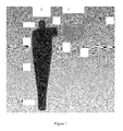
- Fig. 1 is a schematic view of a cyclone based on inlet particle regulation according to one embodiment of the invention.
- the cyclone based on inlet particle regulation is mainly composed of an inlet particle regulator 1 and a cyclone 2, wherein the inlet particle regulator 1 is composed of three parts, namely an inlet 1-1 (a rectangular inlet), a body 1-2 (a cylinder section for centrifugal regulation) and an outlet 1-3 (a rectangular outlet); and the cyclone 2 is composed of five parts, namely an inlet 2-1 (a feed tube), a cylinder section 2-2, a cone section 2-3, an underflow orifice 2-4 and an overflow tube 2-5; a solid-liquid feed mixture enters the inlet particle regulator from the inlet 1-1 and passes through the body 1-2, and then the large particles are distributed from large to small in a direction going from the side wall to the center in the cross-section of the outlet 1-3 before entering the cyclone through the cyclone inlet 2-1 connected therewith
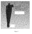
- Fig. 2 is a schematic view of a cyclone based on inlet particle regulation according to another embodiment of the invention.
- the cyclone based on inlet particle regulation is mainly composed of two parts, namely a cylindrical inlet particle regulator 1 and a cyclone 2, wherein the inlet and outlet tubes of the inlet particle regulator are both rectangular while its body is a cylinder; the cyclone is composed of two conventional parts; the outer wall of the outlet tube of the inlet particle regulator is joined to the inner wall of the inlet tube of the cyclone; and the inlet tube of the cyclone is connected to the cylinder section in a tangent form; after a solid-liquid biphase mixture passes through the inlet particle regulator, the particles at the cross-section of the outlet tube are distributed from large to small in a direction going from the outer wall to the inner wall; after entering the inlet tube of the cyclone, the particles at the cross-section of the inlet tube are distributed from small to large in a direction going from the outer wall to the outer wall to
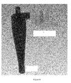
- Fig. 3 is a schematic view of a cyclone based on inlet particle regulation according to yet another embodiment of the invention.
- the cyclone based on inlet particle regulation is mainly composed of two parts, namely a cylindrical inlet particle regulator 1 and a cyclone 2, wherein the outer wall of the outlet tube of the inlet particle regulator is joined to the outer wall of the inlet tube of the cyclone; after a solid-liquid biphase mixture passes through the inlet particle regulator, the particles at the cross-section of the outlet tube are distributed from large to small in a direction going from the outer wall to the inner wall; after entering the inlet tube of the cyclone, the particles at the cross-section of the inlet tube are also distributed from large to small in a direction going from the outer wall to the inner wall; and, as a result, a majority of the small particles go to the overflow tube, while a majority of the large particles go to the underflow orifice, leading to improved classification efficiency of the cyclone.
- Fig. 4 is a schematic view of a cyclone based on inlet particle regulation according to still another embodiment of the invention.
- the cyclone based on inlet particle regulation is mainly composed of two parts, namely an annularly cylindrical inlet particle regulator 1 and a cyclone 2, wherein the body of the inlet particle regulator is an annular cylinder which is used to achieve distribution of the particles at the cross-section of the outlet tube of the inlet particle regulator from large to small in a direction going from the outer wall to the inner wall.
- Fig. 5 is a schematic view of a cyclone based on inlet particle regulation according to another embodiment of the invention.
- the cyclone based on inlet particle regulation is mainly composed of two parts, namely an annularly cylindrical inlet particle regulator 1 and a cyclone 2, wherein the body of the inlet particle regulator is an annular cylinder which is used to achieve distribution of the particles at the cross-section of the outlet tube of the particle regulator from large to small in a direction going from the outer wall to the inner wall.
- the invention combines an inlet particle regulator with an existing cyclone organically to enhance the separation and classification efficiency of the cyclone by regulating the particles (distributing the particles by size) at the cross-section of the cyclone inlet, so that the separation performance of the cyclone used alone is improved in great deal.
- Such a design is advantageous due to its simple structure and high separation efficiency.
- This Example demonstrates a method for improving the separation precision of a cyclone without a particle regulator.
- Fig. 2 two parts composed of a cylindrical inlet particle regulator and a cyclone were used, wherein the inlet and outlet tubes of the inlet particle regulator were both rectangular while its body was a cylinder; the cyclone was composed of conventional parts; the outer wall of the outlet tube of the inlet particle regulator was joined to the inner wall of the inlet tube of the cyclone; and the inlet tube of the cyclone was connected to the cylinder section in a tangent form; after a solid-liquid biphase mixture passed through the inlet particle regulator, the particles at the cross-section of the outlet tube were distributed from large to small in a direction going from the outer wall to the inner wall; after entering the inlet tube of the cyclone, the particles at the cross-section of the inlet tube were distributed from small to large in a direction going from the outer wall to the inner wall; and, as a result, a majority of the small particles went to the underflow
- This Example demonstrates a method for improving the classification efficiency of a cyclone without a particle regulator.
- two parts composed of a cylindrical inlet particle regulator and a cyclone were used.
- This Example was different from Example 1-1 in that the outer wall of the outlet tube of the inlet particle regulator was joined to the outer wall of the inlet tube of the cyclone. After a solid-liquid biphase mixture passed through the inlet particle regulator, the particles at the cross-section of the outlet tube were distributed from large to small in a direction going from the outer wall to the inner wall. After entering the inlet tube of the cyclone, the particles at the cross-section of the inlet tube were also distributed from large to small in a direction going from the outer wall to the inner wall. As a result, a majority of the small particles went to the overflow tube, while a majority of the large particles went to the underflow orifice, leading to improved classification efficiency of the cyclone.
- This Example demonstrates a method for improving the separation precision of a cyclone without a particle regulator.
- a cyclone without a particle regulator.
- two parts composed of an annularly cylindrical inlet particle regulator and a cyclone were used.
- This Example was different from Example 1-1 in that the body of the inlet particle regulator was an annular cylinder which was used to achieve distribution of the particles at the cross-section of the outlet tube of the inlet particle regulator from large to small in a direction going from the outer wall to the inner wall.
- This Example demonstrates a method for improving the classification efficiency of a cyclone without a particle regulator.
- two parts composed of an annularly cylindrical inlet particle regulator and a cyclone were used.
- This Example was different from Example 1-2 in that the body of the particle regulator was an annular cylinder which was used to achieve distribution of the particles at the cross-section of the outlet tube of the particle regulator from large to small in a direction going from the outer wall to the inner wall.
- This Example demonstrates a method for improving the classification efficiency of a cyclone without a particle regulator.
- This Example was different from Example 1-1 in that the body of the inlet particle regulator was an annular cylinder enclosing the overflow tube of the cyclone, and the lower helical tangent outlet was connected to the inlet tube of the cyclone.
- This Example demonstrates a method for improving the classification efficiency of a cyclone without a particle regulator.
- This Example was different from Example 1-1 in that the body of the inlet particle regulator was an annular cylinder enclosing the cylinder section of the cyclone, and the upper helical tangent outlet was connected to the inlet tube of the cyclone.
Landscapes
- Physics & Mathematics (AREA)
- Fluid Mechanics (AREA)
- Cyclones (AREA)
Abstract
Description
- The invention pertains to the field of non-homogeneous solid-liquid separation and solid particle classification, and in particular, relates to a cyclone based on inlet particle regulation that improves the cyclone efficiency of separation and classification by regulating the particles (distributing the particles by size) at the inlet cross-section of the cyclone. The device of the invention may be widely used in energy, chemical engineering, mill run, environmental protection processes, etc. for solid-liquid biphase separation or solid particles classification.
- A cyclone currently used for non-homogeneous separation and solid particle classification is mainly composed of an inlet, a cylinder section, a cone section, an underflow orifice and an overflow orifice. In order to promote the efficiency and precision of cyclone separation, scholars and researchers in related art have conducted extensive and intensive studies on the structure dimension of these parts of a cyclone. However, these studies are limited exclusively to these parts inherent to a cyclone. For example, as the feed pipe is concerned, such forms of inlet structure as involute type, arc type, helix type, concentric circle type and a type featuring multiple pipes arranged symmetrically have been studied and found to have influence on the separation efficiency, precision and energy consumption of a cyclone. Thus, relevant scholars have proposed and invented new cyclones having a helical guide vane, an eccentric volute feeding structure, etc. Nevertheless, study on or application of a method in which a regulating means is added to the inlet to enforce the separation process by way of regulating the inlet particles, i.e. to improve the separation efficiency and precision of an existing cyclone by predistributing the inlet particles, has not yet been reported.
- The separation efficiency and precision of a cyclone separator is affected by three major factors as follows: (1) structure dimension of the cyclone per se; (2) operating parameters; and (3) properties of the material under treatment. The first two aspects have been studied in great deal by scholars and researchers in related art. As to the third aspect, relevant scholars enforce separation by incorporation of fine bubbles or an extractant, i.e. a third phase, in an oil-water (liquid-liquid) cyclone separation process to influence the properties of the material, and improve the efficiency of cyclone separation by addition of a flocculant in a liquid-solid separation process to enlarge solid particle size before the particles enter the cyclone separator, resulting in good application effect. However, for the solid-liquid separation of certain fine slurries, separation precision of lower than 5µm is difficult to be achieved by an existing conventional cyclone separator, and the separation precision can not be improved by introduction of a third phase to modify the properties of the material. It is no doubt that this is a troublesome problem faced by today's researchers.
- Therefore, in view of the problems existing in prior art, there is an urgent need in the art to develop a simple and effective process for improving the efficiency of separation and classification of a cyclone used alone.
- The invention provides a novel cyclone based on inlet particle regulation, eliminating the drawbacks of the prior art.
- The invention provides a novel cyclone based on inlet particle regulation, which is comprised of an inlet particle regulator and a cyclone, wherein the outlet of the inlet particle regulator is connected to the inlet of the cyclone, and the inlet particle regulator is used to achieve distribution of the particles from large to small or from small to large in the inlet cross-section of the cyclone.
- In a preferred embodiment, the inlet cross-section of the cyclone is rectangular.
- In another preferred embodiment, the cross-section of the inlet particle regulator is rectangular.
- In another preferred embodiment, the inlet particle regulator regulates the particles at its outlet by centrifugal force.
- In another preferred embodiment, the body of the inlet particle regulator is a cylinder or annular cylinder.
- In another preferred embodiment, the inlet particle regulator is installed by disposing it near the cyclone inlet or enclosing the outer wall of the cylinder section of the cyclone or the outer wall of the overflow tube.
- In another preferred embodiment, the inlet and the outlet of the inlet particle regulator are communicated with the body of the inlet particle regulator in the form of involute, tangent or helix.
- In another preferred embodiment, the inlet particle regulator is used as a separate particle classification device or as one of a plurality of particle classification devices that are used in collaboration.
- In another preferred embodiment, the inlet of the cyclone is communicated with the cylinder section of the cyclone in the form of involute, tangent or helix.
- In another preferred embodiment, the inlet particle regulator distributes the particles along the inlet cross-section of the cyclone inwardly from large to small to improve the classification efficiency of the cyclone, or from small to large to improve the separation efficiency of the cyclone.
-
-
Fig. 1 is a schematic view of a cyclone based on inlet particle regulation according to one embodiment of the invention. -
Fig. 2 is a schematic view of a cyclone based on inlet particle regulation according to another embodiment of the invention. -
Fig. 3 is a schematic view of a cyclone based on inlet particle regulation according to yet another embodiment of the invention. -
Fig. 4 is a schematic view of a cyclone based on inlet particle regulation according to still another embodiment of the invention. -
Fig. 5 is a schematic view of a cyclone based on inlet particle regulation according to another embodiment of the invention. - After extensive and intensive study, the inventors have found that large particles and small particles interfere with each other during separation. Specifically, in a cyclone, large solid particles moving toward the side wall can block small particles from moving toward the center, and homogeneous solid particles closer to the side wall at the inlet cross-section can be separated more easily to the underflow orifice. Thus, if the particles are predistributed at the inlet before entering the cyclone so that large particles are close to the center and small particles are close to the side wall, the separation precision of the cyclone will be improved effectively. Contrariwise, if it is desired to improve the classification efficiency of the cyclone, the particles at the inlet may be distributed from large to small in a direction going from the side wall to the center. As a result, the separation precision or classification precision of an existing cyclone with a nominal diameter may be improved effectively. The present invention has thus been accomplished on the basis of the foregoing findings.
- The invention provides a cyclone based on inlet particle regulation, which is comprised of an inlet particle regulator and a cyclone, wherein the outlet of the inlet particle regulator is connected to the inlet of the cyclone, and the inlet particle regulator is used to achieve the distribution of the particles from large to small or from small to large in the inlet cross-section of the cyclone, so as to improve the separation performance of the cyclone used alone.
- According to the invention, the inlet particle regulator regulates the particles at its outlet with the help of centrifugal force to achieve distribution of the particles at the inlet cross-section of the cyclone from large to small or from small to large inwardly (in a direction going from the side wall to the center of the cylinder section of the cyclone).
- According to the invention, the body of the inlet particle regulator is a cylinder or annular cylinder (with an additional solid cylinder or hollow cylinder at the center of a larger cylinder) or any other device for distributing particles by size with the help of centrifugal force, wherein its inlet tube is rectangular or circular, and its outlet and the cyclone inlet, each of which may have a rectangular cross-section, are connected.
- According to the invention, the inlet particle regulator is installed by disposing it near the cyclone inlet or enclosing the outer wall of the cylinder section of the cyclone or the outer wall of the overflow tube. Alternatively, in light of an existing cyclone in practical use, it may be designed individually to be installed at the outlet of the existing cyclone to improve separation performance.
- According to the invention, the inlet of the cyclone is communicated with the body (cylinder section) of the cyclone in the form of involute, tangent or helix.
- According to the invention, the inlet particle regulator may be used as a separate particle classification device or in collaboration with other devices.
- Reference will now be made to the drawings.
-
Fig. 1 is a schematic view of a cyclone based on inlet particle regulation according to one embodiment of the invention. As shown inFig. 1 , the cyclone based on inlet particle regulation is mainly composed of an inlet particle regulator 1 and a cyclone 2, wherein the inlet particle regulator 1 is composed of three parts, namely an inlet 1-1 (a rectangular inlet), a body 1-2 (a cylinder section for centrifugal regulation) and an outlet 1-3 (a rectangular outlet); and the cyclone 2 is composed of five parts, namely an inlet 2-1 (a feed tube), a cylinder section 2-2, a cone section 2-3, an underflow orifice 2-4 and an overflow tube 2-5; a solid-liquid feed mixture enters the inlet particle regulator from the inlet 1-1 and passes through the body 1-2, and then the large particles are distributed from large to small in a direction going from the side wall to the center in the cross-section of the outlet 1-3 before entering the cyclone through the cyclone inlet 2-1 connected therewith; the particles in the cross-section of the feed tube may be distributed from large to small or from small to large in a direction going from the side wall to the center, dependent on different separation or classification; and, after entering the cyclone, the mixture is separated through the cylinder section 2-2 and the cone section 2-3, and then the supernatant is discharged from the overflow tube 2-5 while the concentrated liquid containing the solid particles is discharged from the underflow orifice 2-4. -
Fig. 2 is a schematic view of a cyclone based on inlet particle regulation according to another embodiment of the invention. As shown inFig. 2 , the cyclone based on inlet particle regulation is mainly composed of two parts, namely a cylindricalinlet particle regulator 1 and acyclone 2, wherein the inlet and outlet tubes of the inlet particle regulator are both rectangular while its body is a cylinder; the cyclone is composed of two conventional parts; the outer wall of the outlet tube of the inlet particle regulator is joined to the inner wall of the inlet tube of the cyclone; and the inlet tube of the cyclone is connected to the cylinder section in a tangent form; after a solid-liquid biphase mixture passes through the inlet particle regulator, the particles at the cross-section of the outlet tube are distributed from large to small in a direction going from the outer wall to the inner wall; after entering the inlet tube of the cyclone, the particles at the cross-section of the inlet tube are distributed from small to large in a direction going from the outer wall to the inner wall; as a result, a majority of the small particles go to the underflow orifice to be separated out; therefore, the efficiency of the cyclone for separating small particles is improved, and the separation precision of the cyclone is thus promoted. -
Fig. 3 is a schematic view of a cyclone based on inlet particle regulation according to yet another embodiment of the invention. As shown inFig. 3 , the cyclone based on inlet particle regulation is mainly composed of two parts, namely a cylindricalinlet particle regulator 1 and acyclone 2, wherein the outer wall of the outlet tube of the inlet particle regulator is joined to the outer wall of the inlet tube of the cyclone; after a solid-liquid biphase mixture passes through the inlet particle regulator, the particles at the cross-section of the outlet tube are distributed from large to small in a direction going from the outer wall to the inner wall; after entering the inlet tube of the cyclone, the particles at the cross-section of the inlet tube are also distributed from large to small in a direction going from the outer wall to the inner wall; and, as a result, a majority of the small particles go to the overflow tube, while a majority of the large particles go to the underflow orifice, leading to improved classification efficiency of the cyclone. -
Fig. 4 is a schematic view of a cyclone based on inlet particle regulation according to still another embodiment of the invention. As shown inFig. 4 , the cyclone based on inlet particle regulation is mainly composed of two parts, namely an annularly cylindricalinlet particle regulator 1 and acyclone 2, wherein the body of the inlet particle regulator is an annular cylinder which is used to achieve distribution of the particles at the cross-section of the outlet tube of the inlet particle regulator from large to small in a direction going from the outer wall to the inner wall. -
Fig. 5 is a schematic view of a cyclone based on inlet particle regulation according to another embodiment of the invention. As shown inFig. 5 , the cyclone based on inlet particle regulation is mainly composed of two parts, namely an annularly cylindricalinlet particle regulator 1 and acyclone 2, wherein the body of the inlet particle regulator is an annular cylinder which is used to achieve distribution of the particles at the cross-section of the outlet tube of the particle regulator from large to small in a direction going from the outer wall to the inner wall. - The main advantages of the process and the device of the invention include:
- The invention combines an inlet particle regulator with an existing cyclone organically to enhance the separation and classification efficiency of the cyclone by regulating the particles (distributing the particles by size) at the cross-section of the cyclone inlet, so that the separation performance of the cyclone used alone is improved in great deal. Such a design is advantageous due to its simple structure and high separation efficiency.
- The invention will be further illustrated with reference to the following specific Examples. However, it is to be appreciated that these Examples are only intended to demonstrate the invention without limiting the scope of the invention. The test methods in the following Examples for which no specific conditions are indicated will be carried out generally under conventional conditions or under those conditions suggested by the manufacturers. Unless otherwise specified, all percentages and parts are based on weight.
- This Example demonstrates a method for improving the separation precision of a cyclone without a particle regulator. As shown in
Fig. 2 , two parts composed of a cylindrical inlet particle regulator and a cyclone were used, wherein the inlet and outlet tubes of the inlet particle regulator were both rectangular while its body was a cylinder; the cyclone was composed of conventional parts; the outer wall of the outlet tube of the inlet particle regulator was joined to the inner wall of the inlet tube of the cyclone; and the inlet tube of the cyclone was connected to the cylinder section in a tangent form; after a solid-liquid biphase mixture passed through the inlet particle regulator, the particles at the cross-section of the outlet tube were distributed from large to small in a direction going from the outer wall to the inner wall; after entering the inlet tube of the cyclone, the particles at the cross-section of the inlet tube were distributed from small to large in a direction going from the outer wall to the inner wall; and, as a result, a majority of the small particles went to the underflow orifice to be separated out. Therefore, the efficiency of the cyclone for separating small particles was improved, and the separation precision of the cyclone was thus promoted. - This Example demonstrates a method for improving the classification efficiency of a cyclone without a particle regulator. As shown in
Fig. 3 , two parts composed of a cylindrical inlet particle regulator and a cyclone were used. This Example was different from Example 1-1 in that the outer wall of the outlet tube of the inlet particle regulator was joined to the outer wall of the inlet tube of the cyclone. After a solid-liquid biphase mixture passed through the inlet particle regulator, the particles at the cross-section of the outlet tube were distributed from large to small in a direction going from the outer wall to the inner wall. After entering the inlet tube of the cyclone, the particles at the cross-section of the inlet tube were also distributed from large to small in a direction going from the outer wall to the inner wall. As a result, a majority of the small particles went to the overflow tube, while a majority of the large particles went to the underflow orifice, leading to improved classification efficiency of the cyclone. - This Example demonstrates a method for improving the separation precision of a cyclone without a particle regulator. As shown in
Fig. 4 , two parts composed of an annularly cylindrical inlet particle regulator and a cyclone were used. This Example was different from Example 1-1 in that the body of the inlet particle regulator was an annular cylinder which was used to achieve distribution of the particles at the cross-section of the outlet tube of the inlet particle regulator from large to small in a direction going from the outer wall to the inner wall. - This Example demonstrates a method for improving the classification efficiency of a cyclone without a particle regulator. As shown in
Fig. 5 , two parts composed of an annularly cylindrical inlet particle regulator and a cyclone were used. This Example was different from Example 1-2 in that the body of the particle regulator was an annular cylinder which was used to achieve distribution of the particles at the cross-section of the outlet tube of the particle regulator from large to small in a direction going from the outer wall to the inner wall. - This Example demonstrates a method for improving the classification efficiency of a cyclone without a particle regulator. This Example was different from Example 1-1 in that the body of the inlet particle regulator was an annular cylinder enclosing the overflow tube of the cyclone, and the lower helical tangent outlet was connected to the inlet tube of the cyclone.
- This Example demonstrates a method for improving the classification efficiency of a cyclone without a particle regulator. This Example was different from Example 1-1 in that the body of the inlet particle regulator was an annular cylinder enclosing the cylinder section of the cyclone, and the upper helical tangent outlet was connected to the inlet tube of the cyclone.
- All of the literatures mentioned in the invention are incorporated herein by reference, as if each of them were independently incorporated herein by reference. In addition, it is to be understood that, after reading the above teachings of the invention, persons skilled in the art can make various changes or modifications to the invention, and these equivalents are to be included in the scope defined by the appended claims as well.
Claims (10)
- A cyclone based on inlet particle regulation, comprised of an inlet particle regulator (1) and a cyclone (2), wherein the outlet (1-3) of the inlet particle regulator is connected to the inlet (2-1) of the cyclone, and the inlet particle regulator is used to achieve distribution of particles in the inlet cross-section of the cyclone from large to small or from small to large.
- The cyclone based on inlet particle regulation of Claim 1, wherein the inlet cross-section of the cyclone is rectangular.
- The cyclone based on inlet particle regulation of Claim 1 or 2, wherein the cross-section of the inlet particle regulator is rectangular.
- The cyclone based on inlet particle regulation of Claim 1, wherein the inlet particle regulator regulates the particles at its outlet by centrifugal force.
- The cyclone based on inlet particle regulation of Claim 1, wherein the body (1-2) of the inlet particle regulator is a cylinder or annular cylinder.
- The cyclone based on inlet particle regulation of Claim 1, wherein the inlet particle regulator is installed by disposing it near the cyclone inlet or enclosing the outer wall of the cylinder section (2-2) of the cyclone or the outer wall of the overflow tube (2-5).
- The cyclone based on inlet particle regulation of Claim 1, wherein the inlet (1-1) and the outlet (1-3) of the inlet particle regulator are communicated with the body (1-2) of the inlet particle regulator in the form of involute, tangent or helix.
- The cyclone based on inlet particle regulation of Claim 1, wherein the inlet particle regulator is used as a separate particle classification device or as one of a plurality of particle classification devices that are used in collaboration.
- The cyclone based on inlet particle regulation of Claim 1, wherein the inlet (2-1) of the cyclone is communicated with the cylinder section (2-2) of the cyclone in the form of involute, tangent or helix.
- The cyclone based on inlet particle regulation of Claim 1, wherein the inlet particle regulator distributes the particles along the inlet cross-section of the cyclone inwardly from large to small to improve the classification efficiency of the cyclone, or from small to large to improve the separation efficiency of the cyclone.
Applications Claiming Priority (2)
| Application Number | Priority Date | Filing Date | Title |
|---|---|---|---|
| CN201010533906.1A CN101972717B (en) | 2010-11-05 | 2010-11-05 | Swirler based on inlet particle regulating |
| PCT/CN2011/072705 WO2012058900A1 (en) | 2010-11-05 | 2011-04-13 | Swirling device using inlet particle regulation |
Publications (3)
| Publication Number | Publication Date |
|---|---|
| EP2620222A1 true EP2620222A1 (en) | 2013-07-31 |
| EP2620222A4 EP2620222A4 (en) | 2013-10-16 |
| EP2620222B1 EP2620222B1 (en) | 2016-02-10 |
Family
ID=43572642
Family Applications (1)
| Application Number | Title | Priority Date | Filing Date |
|---|---|---|---|
| EP11824292.4A Not-in-force EP2620222B1 (en) | 2010-11-05 | 2011-04-13 | Swirling device using inlet particle regulation |
Country Status (4)
| Country | Link |
|---|---|
| US (1) | US20130298510A1 (en) |
| EP (1) | EP2620222B1 (en) |
| CN (1) | CN101972717B (en) |
| WO (1) | WO2012058900A1 (en) |
Families Citing this family (2)
| Publication number | Priority date | Publication date | Assignee | Title |
|---|---|---|---|---|
| CN101972717B (en) * | 2010-11-05 | 2013-09-18 | 华东理工大学 | Swirler based on inlet particle regulating |
| US20180216818A1 (en) * | 2017-01-30 | 2018-08-02 | Detroit Stoker Company | Ash treatment and reinjection system |
Family Cites Families (19)
| Publication number | Priority date | Publication date | Assignee | Title |
|---|---|---|---|---|
| BE434678A (en) * | 1938-06-20 | |||
| US3091334A (en) * | 1959-07-20 | 1963-05-28 | Denver Equip Co | Centrifugal separation method and means |
| US3865242A (en) * | 1972-12-15 | 1975-02-11 | Combustion Eng | Upstream classifier for a multi-separator |
| US4399027A (en) * | 1979-11-15 | 1983-08-16 | University Of Utah Research Foundation | Flotation apparatus and method for achieving flotation in a centrifugal field |
| GB2116457A (en) * | 1982-03-13 | 1983-09-28 | British Petroleum Co Plc | Inlet mechanism for cyclone separator |
| US5180486A (en) * | 1989-11-28 | 1993-01-19 | Lsr Environmental Systems Company | Potential flow centrifugal separator system for removing solid particulates from a fluid stream |
| US5591253A (en) * | 1995-03-07 | 1997-01-07 | Electric Power Research Institute, Inc. | Electrostatically enhanced separator (EES) |
| US5566835A (en) * | 1995-10-05 | 1996-10-22 | Beloit Technologies, Inc. | Cleaner with inverted hydrocyclone |
| US6193075B1 (en) * | 1996-09-30 | 2001-02-27 | Colgate-Palmolive Company | Air classification of animal by-products |
| US6238579B1 (en) * | 1998-05-12 | 2001-05-29 | Mba Polymers, Inc. | Device for separating solid particles in a fluid stream |
| US6896720B1 (en) * | 1999-02-18 | 2005-05-24 | Adrian Christopher Arnold | Cleaning apparatus |
| GB9930332D0 (en) * | 1999-12-22 | 2000-02-09 | Notetry Ltd | Cyclonic separating apparatus |
| EP1767276A1 (en) * | 2005-09-22 | 2007-03-28 | K.K. Fukuma Technica | Cyclone apparatus with preliminary swirling unit and powder dust remover or automobile including the apparatus |
| US8403149B2 (en) * | 2005-11-18 | 2013-03-26 | Ricoh Company, Ltd. | Cyclone classifier, flash drying system using the cyclone classifier, and toner prepared by the flash drying system |
| JP5604101B2 (en) * | 2006-05-24 | 2014-10-08 | エクソンモービル・ケミカル・パテンツ・インク | Production of monoalkylated aromatic compounds |
| GB2446580B (en) * | 2007-02-16 | 2011-09-14 | Siemens Vai Metals Tech Ltd | Cyclone with classifier inlet and small particle by-pass |
| CN101391239B (en) * | 2008-10-30 | 2010-09-01 | 青岛科技大学 | Multiple-effect cyclone separating device |
| CN101780440A (en) * | 2009-01-20 | 2010-07-21 | 扬州金鑫陶瓷复合钢管有限公司 | Polyurethane cyclone |
| CN101972717B (en) * | 2010-11-05 | 2013-09-18 | 华东理工大学 | Swirler based on inlet particle regulating |
-
2010
- 2010-11-05 CN CN201010533906.1A patent/CN101972717B/en active Active
-
2011
- 2011-04-13 EP EP11824292.4A patent/EP2620222B1/en not_active Not-in-force
- 2011-04-13 US US13/496,278 patent/US20130298510A1/en not_active Abandoned
- 2011-04-13 WO PCT/CN2011/072705 patent/WO2012058900A1/en not_active Ceased
Also Published As
| Publication number | Publication date |
|---|---|
| EP2620222B1 (en) | 2016-02-10 |
| WO2012058900A1 (en) | 2012-05-10 |
| CN101972717B (en) | 2013-09-18 |
| EP2620222A4 (en) | 2013-10-16 |
| CN101972717A (en) | 2011-02-16 |
| US20130298510A1 (en) | 2013-11-14 |
Similar Documents
| Publication | Publication Date | Title |
|---|---|---|
| CN104307288B (en) | The coalescent gas-liquid separator of a kind of high-efficiency cyclone | |
| US8021559B2 (en) | Thickening apparatus and method for thickening | |
| AU2007316099B2 (en) | Thickener and method for thickening | |
| US8715513B2 (en) | Modified compact oil-water separation device and systems and methods for use thereof | |
| KR20150039775A (en) | Apparatus for cyclone separation of a fluid flow into a gas phase and a liquid phase and vessel provided with such an apparatus | |
| CN204564371U (en) | Utilize magnetic force strong permanent magnet mineral water power cyclone classification device | |
| ZA200507392B (en) | A separate size flotation device | |
| CA2479326A1 (en) | Dual zone feedwell for a thickener | |
| CN103301659B (en) | A feed stabilizing device for a concentrator | |
| EP2620222B1 (en) | Swirling device using inlet particle regulation | |
| CN105689154B (en) | A kind of black water flotation unit and technique | |
| CN200991662Y (en) | Cascade type cyclone separator | |
| US20230062956A1 (en) | External loop slurry reactor | |
| WO2006036014A1 (en) | Coagulation-separation apparatus | |
| CN109225687B (en) | Hydrocyclone with cone slotting structure | |
| CN204051949U (en) | A kind of monomer multi-stag classification and sorting small-angle hydrocyclone | |
| CN211160267U (en) | Secondary slurry making and water supplementing cyclone | |
| CN205323288U (en) | Flowing back oil water separator is returned in well workover and flowing back water oil separating assembly is returned in well workover | |
| MX2008002000A (en) | Improvements in and relating to hydrocyclones. | |
| CN205008122U (en) | Slight irrigation is with high -efficient silt particle ware that removes of combination water conservancy whirl | |
| CN115518779A (en) | A kind of oily sewage cyclone separation device and separation method | |
| CN109332018B (en) | Hydraulic cyclone | |
| CN212651479U (en) | Novel steam-water separator | |
| CN108296032A (en) | A kind of hydrocyclone of high-efficiency low-resistance | |
| CN104888667A (en) | Fischer-Tropsch synthesis product separation system and method of slurry bed reactor |
Legal Events
| Date | Code | Title | Description |
|---|---|---|---|
| PUAI | Public reference made under article 153(3) epc to a published international application that has entered the european phase |
Free format text: ORIGINAL CODE: 0009012 |
|
| 17P | Request for examination filed |
Effective date: 20120320 |
|
| AK | Designated contracting states |
Kind code of ref document: A1 Designated state(s): AL AT BE BG CH CY CZ DE DK EE ES FI FR GB GR HR HU IE IS IT LI LT LU LV MC MK MT NL NO PL PT RO RS SE SI SK SM TR |
|
| A4 | Supplementary search report drawn up and despatched |
Effective date: 20130912 |
|
| RIC1 | Information provided on ipc code assigned before grant |
Ipc: B04C 5/02 20060101ALI20130906BHEP Ipc: B04C 11/00 20060101ALI20130906BHEP Ipc: B04C 9/00 20060101AFI20130906BHEP |
|
| DAX | Request for extension of the european patent (deleted) | ||
| 17Q | First examination report despatched |
Effective date: 20141103 |
|
| GRAP | Despatch of communication of intention to grant a patent |
Free format text: ORIGINAL CODE: EPIDOSNIGR1 |
|
| INTG | Intention to grant announced |
Effective date: 20150806 |
|
| GRAS | Grant fee paid |
Free format text: ORIGINAL CODE: EPIDOSNIGR3 |
|
| GRAA | (expected) grant |
Free format text: ORIGINAL CODE: 0009210 |
|
| AK | Designated contracting states |
Kind code of ref document: B1 Designated state(s): AL AT BE BG CH CY CZ DE DK EE ES FI FR GB GR HR HU IE IS IT LI LT LU LV MC MK MT NL NO PL PT RO RS SE SI SK SM TR |
|
| REG | Reference to a national code |
Ref country code: GB Ref legal event code: FG4D |
|
| REG | Reference to a national code |
Ref country code: AT Ref legal event code: REF Ref document number: 774378 Country of ref document: AT Kind code of ref document: T Effective date: 20160215 Ref country code: CH Ref legal event code: EP |
|
| REG | Reference to a national code |
Ref country code: IE Ref legal event code: FG4D |
|
| REG | Reference to a national code |
Ref country code: DE Ref legal event code: R096 Ref document number: 602011023293 Country of ref document: DE |
|
| REG | Reference to a national code |
Ref country code: NL Ref legal event code: FP |
|
| REG | Reference to a national code |
Ref country code: LT Ref legal event code: MG4D |
|
| REG | Reference to a national code |
Ref country code: AT Ref legal event code: MK05 Ref document number: 774378 Country of ref document: AT Kind code of ref document: T Effective date: 20160210 |
|
| PG25 | Lapsed in a contracting state [announced via postgrant information from national office to epo] |
Ref country code: ES Free format text: LAPSE BECAUSE OF FAILURE TO SUBMIT A TRANSLATION OF THE DESCRIPTION OR TO PAY THE FEE WITHIN THE PRESCRIBED TIME-LIMIT Effective date: 20160210 Ref country code: HR Free format text: LAPSE BECAUSE OF FAILURE TO SUBMIT A TRANSLATION OF THE DESCRIPTION OR TO PAY THE FEE WITHIN THE PRESCRIBED TIME-LIMIT Effective date: 20160210 Ref country code: NO Free format text: LAPSE BECAUSE OF FAILURE TO SUBMIT A TRANSLATION OF THE DESCRIPTION OR TO PAY THE FEE WITHIN THE PRESCRIBED TIME-LIMIT Effective date: 20160510 Ref country code: FI Free format text: LAPSE BECAUSE OF FAILURE TO SUBMIT A TRANSLATION OF THE DESCRIPTION OR TO PAY THE FEE WITHIN THE PRESCRIBED TIME-LIMIT Effective date: 20160210 Ref country code: GR Free format text: LAPSE BECAUSE OF FAILURE TO SUBMIT A TRANSLATION OF THE DESCRIPTION OR TO PAY THE FEE WITHIN THE PRESCRIBED TIME-LIMIT Effective date: 20160511 Ref country code: IT Free format text: LAPSE BECAUSE OF FAILURE TO SUBMIT A TRANSLATION OF THE DESCRIPTION OR TO PAY THE FEE WITHIN THE PRESCRIBED TIME-LIMIT Effective date: 20160210 |
|
| PG25 | Lapsed in a contracting state [announced via postgrant information from national office to epo] |
Ref country code: IS Free format text: LAPSE BECAUSE OF FAILURE TO SUBMIT A TRANSLATION OF THE DESCRIPTION OR TO PAY THE FEE WITHIN THE PRESCRIBED TIME-LIMIT Effective date: 20160610 Ref country code: PL Free format text: LAPSE BECAUSE OF FAILURE TO SUBMIT A TRANSLATION OF THE DESCRIPTION OR TO PAY THE FEE WITHIN THE PRESCRIBED TIME-LIMIT Effective date: 20160210 Ref country code: RS Free format text: LAPSE BECAUSE OF FAILURE TO SUBMIT A TRANSLATION OF THE DESCRIPTION OR TO PAY THE FEE WITHIN THE PRESCRIBED TIME-LIMIT Effective date: 20160210 Ref country code: LV Free format text: LAPSE BECAUSE OF FAILURE TO SUBMIT A TRANSLATION OF THE DESCRIPTION OR TO PAY THE FEE WITHIN THE PRESCRIBED TIME-LIMIT Effective date: 20160210 Ref country code: SE Free format text: LAPSE BECAUSE OF FAILURE TO SUBMIT A TRANSLATION OF THE DESCRIPTION OR TO PAY THE FEE WITHIN THE PRESCRIBED TIME-LIMIT Effective date: 20160210 Ref country code: LT Free format text: LAPSE BECAUSE OF FAILURE TO SUBMIT A TRANSLATION OF THE DESCRIPTION OR TO PAY THE FEE WITHIN THE PRESCRIBED TIME-LIMIT Effective date: 20160210 Ref country code: AT Free format text: LAPSE BECAUSE OF FAILURE TO SUBMIT A TRANSLATION OF THE DESCRIPTION OR TO PAY THE FEE WITHIN THE PRESCRIBED TIME-LIMIT Effective date: 20160210 Ref country code: PT Free format text: LAPSE BECAUSE OF FAILURE TO SUBMIT A TRANSLATION OF THE DESCRIPTION OR TO PAY THE FEE WITHIN THE PRESCRIBED TIME-LIMIT Effective date: 20160613 Ref country code: BE Free format text: LAPSE BECAUSE OF NON-PAYMENT OF DUE FEES Effective date: 20160430 |
|
| PG25 | Lapsed in a contracting state [announced via postgrant information from national office to epo] |
Ref country code: DK Free format text: LAPSE BECAUSE OF FAILURE TO SUBMIT A TRANSLATION OF THE DESCRIPTION OR TO PAY THE FEE WITHIN THE PRESCRIBED TIME-LIMIT Effective date: 20160210 Ref country code: EE Free format text: LAPSE BECAUSE OF FAILURE TO SUBMIT A TRANSLATION OF THE DESCRIPTION OR TO PAY THE FEE WITHIN THE PRESCRIBED TIME-LIMIT Effective date: 20160210 |
|
| REG | Reference to a national code |
Ref country code: DE Ref legal event code: R119 Ref document number: 602011023293 Country of ref document: DE |
|
| PG25 | Lapsed in a contracting state [announced via postgrant information from national office to epo] |
Ref country code: SK Free format text: LAPSE BECAUSE OF FAILURE TO SUBMIT A TRANSLATION OF THE DESCRIPTION OR TO PAY THE FEE WITHIN THE PRESCRIBED TIME-LIMIT Effective date: 20160210 Ref country code: CZ Free format text: LAPSE BECAUSE OF FAILURE TO SUBMIT A TRANSLATION OF THE DESCRIPTION OR TO PAY THE FEE WITHIN THE PRESCRIBED TIME-LIMIT Effective date: 20160210 Ref country code: RO Free format text: LAPSE BECAUSE OF FAILURE TO SUBMIT A TRANSLATION OF THE DESCRIPTION OR TO PAY THE FEE WITHIN THE PRESCRIBED TIME-LIMIT Effective date: 20160210 Ref country code: SM Free format text: LAPSE BECAUSE OF FAILURE TO SUBMIT A TRANSLATION OF THE DESCRIPTION OR TO PAY THE FEE WITHIN THE PRESCRIBED TIME-LIMIT Effective date: 20160210 |
|
| REG | Reference to a national code |
Ref country code: CH Ref legal event code: PL |
|
| PLBE | No opposition filed within time limit |
Free format text: ORIGINAL CODE: 0009261 |
|
| STAA | Information on the status of an ep patent application or granted ep patent |
Free format text: STATUS: NO OPPOSITION FILED WITHIN TIME LIMIT |
|
| PG25 | Lapsed in a contracting state [announced via postgrant information from national office to epo] |
Ref country code: LU Free format text: LAPSE BECAUSE OF FAILURE TO SUBMIT A TRANSLATION OF THE DESCRIPTION OR TO PAY THE FEE WITHIN THE PRESCRIBED TIME-LIMIT Effective date: 20160413 Ref country code: BE Free format text: LAPSE BECAUSE OF FAILURE TO SUBMIT A TRANSLATION OF THE DESCRIPTION OR TO PAY THE FEE WITHIN THE PRESCRIBED TIME-LIMIT Effective date: 20160210 |
|
| 26N | No opposition filed |
Effective date: 20161111 |
|
| GBPC | Gb: european patent ceased through non-payment of renewal fee |
Effective date: 20160510 |
|
| REG | Reference to a national code |
Ref country code: IE Ref legal event code: MM4A |
|
| REG | Reference to a national code |
Ref country code: FR Ref legal event code: ST Effective date: 20161230 |
|
| PG25 | Lapsed in a contracting state [announced via postgrant information from national office to epo] |
Ref country code: DE Free format text: LAPSE BECAUSE OF NON-PAYMENT OF DUE FEES Effective date: 20161101 Ref country code: CH Free format text: LAPSE BECAUSE OF NON-PAYMENT OF DUE FEES Effective date: 20160430 Ref country code: LI Free format text: LAPSE BECAUSE OF NON-PAYMENT OF DUE FEES Effective date: 20160430 Ref country code: FR Free format text: LAPSE BECAUSE OF NON-PAYMENT OF DUE FEES Effective date: 20160502 |
|
| PG25 | Lapsed in a contracting state [announced via postgrant information from national office to epo] |
Ref country code: BG Free format text: LAPSE BECAUSE OF FAILURE TO SUBMIT A TRANSLATION OF THE DESCRIPTION OR TO PAY THE FEE WITHIN THE PRESCRIBED TIME-LIMIT Effective date: 20160510 Ref country code: SI Free format text: LAPSE BECAUSE OF FAILURE TO SUBMIT A TRANSLATION OF THE DESCRIPTION OR TO PAY THE FEE WITHIN THE PRESCRIBED TIME-LIMIT Effective date: 20160210 |
|
| PG25 | Lapsed in a contracting state [announced via postgrant information from national office to epo] |
Ref country code: GB Free format text: LAPSE BECAUSE OF NON-PAYMENT OF DUE FEES Effective date: 20160510 Ref country code: IE Free format text: LAPSE BECAUSE OF NON-PAYMENT OF DUE FEES Effective date: 20160413 |
|
| PG25 | Lapsed in a contracting state [announced via postgrant information from national office to epo] |
Ref country code: CY Free format text: LAPSE BECAUSE OF FAILURE TO SUBMIT A TRANSLATION OF THE DESCRIPTION OR TO PAY THE FEE WITHIN THE PRESCRIBED TIME-LIMIT Effective date: 20160210 Ref country code: HU Free format text: LAPSE BECAUSE OF FAILURE TO SUBMIT A TRANSLATION OF THE DESCRIPTION OR TO PAY THE FEE WITHIN THE PRESCRIBED TIME-LIMIT; INVALID AB INITIO Effective date: 20110413 |
|
| PG25 | Lapsed in a contracting state [announced via postgrant information from national office to epo] |
Ref country code: MK Free format text: LAPSE BECAUSE OF FAILURE TO SUBMIT A TRANSLATION OF THE DESCRIPTION OR TO PAY THE FEE WITHIN THE PRESCRIBED TIME-LIMIT Effective date: 20160210 Ref country code: MT Free format text: LAPSE BECAUSE OF NON-PAYMENT OF DUE FEES Effective date: 20160430 Ref country code: MC Free format text: LAPSE BECAUSE OF FAILURE TO SUBMIT A TRANSLATION OF THE DESCRIPTION OR TO PAY THE FEE WITHIN THE PRESCRIBED TIME-LIMIT Effective date: 20160210 Ref country code: TR Free format text: LAPSE BECAUSE OF FAILURE TO SUBMIT A TRANSLATION OF THE DESCRIPTION OR TO PAY THE FEE WITHIN THE PRESCRIBED TIME-LIMIT Effective date: 20160210 |
|
| PG25 | Lapsed in a contracting state [announced via postgrant information from national office to epo] |
Ref country code: AL Free format text: LAPSE BECAUSE OF FAILURE TO SUBMIT A TRANSLATION OF THE DESCRIPTION OR TO PAY THE FEE WITHIN THE PRESCRIBED TIME-LIMIT Effective date: 20160210 |
|
| PGFP | Annual fee paid to national office [announced via postgrant information from national office to epo] |
Ref country code: NL Payment date: 20230417 Year of fee payment: 13 |
|
| REG | Reference to a national code |
Ref country code: NL Ref legal event code: MM Effective date: 20240501 |
|
| PG25 | Lapsed in a contracting state [announced via postgrant information from national office to epo] |
Ref country code: NL Free format text: LAPSE BECAUSE OF NON-PAYMENT OF DUE FEES Effective date: 20240501 |
|
| PG25 | Lapsed in a contracting state [announced via postgrant information from national office to epo] |
Ref country code: NL Free format text: LAPSE BECAUSE OF NON-PAYMENT OF DUE FEES Effective date: 20240501 |