EP2620183B1 - Fire extinguisher safety mechanism - Google Patents
Fire extinguisher safety mechanism Download PDFInfo
- Publication number
- EP2620183B1 EP2620183B1 EP12195557.9A EP12195557A EP2620183B1 EP 2620183 B1 EP2620183 B1 EP 2620183B1 EP 12195557 A EP12195557 A EP 12195557A EP 2620183 B1 EP2620183 B1 EP 2620183B1
- Authority
- EP
- European Patent Office
- Prior art keywords
- safety mechanism
- shank
- fire extinguisher
- distal end
- release member
- Prior art date
- Legal status (The legal status is an assumption and is not a legal conclusion. Google has not performed a legal analysis and makes no representation as to the accuracy of the status listed.)
- Active
Links
Images


Classifications
-
- A—HUMAN NECESSITIES
- A62—LIFE-SAVING; FIRE-FIGHTING
- A62C—FIRE-FIGHTING
- A62C13/00—Portable extinguishers which are permanently pressurised or pressurised immediately before use
- A62C13/76—Details or accessories
-
- A—HUMAN NECESSITIES
- A62—LIFE-SAVING; FIRE-FIGHTING
- A62C—FIRE-FIGHTING
- A62C37/00—Control of fire-fighting equipment
- A62C37/50—Testing or indicating devices for determining the state of readiness of the equipment
Definitions
- the present invention relates to fire extinguishers and in particular to fire extinguisher safety mechanisms.
- Fire extinguishers frequently include a safety mechanism which prevents accidental discharge of the extinguisher.
- One such mechanism comprises a pin which extends through the handle of the extinguisher.
- the pin has a handle at one end which can be pulled by a user when he or she wishes to use the extinguisher. The pulling action breaks a part of the pin allowing it to be withdrawn from the extinguisher handle and allowing the extinguisher then to be used. The broken pin also indicates that the extinguisher has been used.
- An example of such an extinguisher is disclosed in US-A-3844356 .
- the end of a pin remote from the pin handle is weakened such that when it is pulled from the extinguisher it breaks, allowing an indicator member to fall away. This indicates that the extinguisher has been used.
- This type of design has been used by the Applicant for some 20 years.
- a problem with such designs is that the pin handle projects from one side of the extinguisher body, i.e. it is a "handed" arrangement which may be inconvenient for a user.
- a further problem is that the pin breaks in tension which may make construction of the pin more difficult or breaking of the pin more difficult.
- the present invention seeks to overcome or at least mitigate the above problems.
- GB 2322298 A discloses a fire extinguisher safety mechanism having the features of the preamble of claim 1.
- JP S50 59894 U discloses an indicator for a fire extinguisher safety mechanism.
- the present invention provides a fire extinguisher safety mechanism.
- the mechanism as set forth in claim 1.
- the user pulls a release member lengthwise from between the handles. Pulling the release member in this manner will cause the shank of the indicator member to shear, allowing the release member to be removed from between the handles. One of the handles can then be moved relative to the other to operate the extinguisher. The indicator member will no longer be retained and will simply fall away indicating that the extinguisher has been used. As its shank has been sheared, it cannot be used again.
- the head of the indicator member may be relatively thin and may for example be disc like. It may be circular in shape or have any desired shape, for example a polygonal shape.
- the head may carry an inscription, for example "OK", to indicate that the extinguisher has not been used.
- the indicator member may be brightly coloured. It may be made from a fluorescent, phosphorescent, luminescent or other 'glow in the dark' material.
- the colour of the indicator may be varied to, for example, indicate its year of manufacture or servicing of the extinguisher, thereby giving the user an indication of the period in which the extinguisher has not been operated. Up to 20 wt% of a coloured and/or luminous additive may be added to the material of the indicator.
- the indicator member may be moulded from a plastics material, for example a polystyrene material.
- the material should desirably be chosen such that the shank of the indicator member shears without excessive strain, i.e. such that it does not stretch excessively. It the material stretches, it will break in tension rather than in shear which is undesirable since the force required to break the shank would typically be twice as high in tension as in shear.
- a desirable breaking force in some applications is less than 100N, for example below 80N.
- regrind (particularly of the same material of the virgin material) may be added to the virgin material. This reduces the strength of the virgin material. In one example, between 2-10 wt% regrind, more narrowly 4-6 wt%, for example 5% regrind may be used.
- a material which has proven particularly suitable is EDISTIR N1840, with 5 wt% EDISTIR N1840 regrind.
- the indicator member head may be configured to be received by a complementary area provided on the extinguisher head, more particularly an area on the movable handle of the extinguisher. That area may carry an inscription such as "USED" which becomes visible once the indicator member head has fallen away, thereby indicating that the extinguisher has been used.
- the inscription may be embossed, printed or otherwise provided on the extinguisher head.
- the shank may be provided with one or more areas of weakness. This area of weakness may be in an intermediate region of the shank.
- the shank is provided with a through hole which effectively reduces the thickness of the shank.
- a through hole may be provided in a waisted region of the shank. This not only reduces the force necessary to shear the shank but also to improve flow of material in the mould during the moulding of the indicator member.
- the shank may be stepped in order to provide a first region for engaging in the aperture provided in the extinguisher head and a second region, smaller in cross section than the first region, for engaging in the aperture provided in the release member.
- a proximal portion of the shank adjacent the head may taper towards the distal end of the shank. This avoids a columnar shank which potentially could be reinserted in the aperture in the extinguisher head after use, which is undesirable.
- the resilient retaining means provided on the distal end of the shank may be barb-like, for example formed on the ends of flexible legs formed by a slot in the distal end of the shank. The barbs prevent the indicator member being withdrawn from the release member once the indicator member has been inserted.
- the distal end of the shank may have a profile which is at least in part complementary to that of the aperture in the distal end of the release member. This is advantageous in that it helps locate the indicator in the release member and reduces twisting of the shank as the release member is withdrawn, thereby reducing the chances of the shank breaking in tension rather than in shear.
- the lateral surfaces of the flexible legs of the retaining means may be formed as flat surfaces, particularly parallel flat surfaces, to cooperate with complementary surface in the aperture in the release member.
- Alignment means may be provided to align the indicator member in an appropriate orientation on the extinguisher, so that, for example, any inscription is easily readable by a user.
- the rear surface of the head of the indicator member is provided with a formation, for example one or more projections which engages with a corresponding formation on the extinguisher.
- the rear surface of the head is provided with a rib which engages under the lower edge of the handle to which the indicator member is mounted.
- the indicator member is broken and, once the extinguisher is re-charged, must be replaced.
- the proximal end thereof may comprise an aperture through which a user may place one or more fingers to pull the release member from between the extinguisher handles.
- the distal end of the release member may be provided with a clip for engaging a part of the extinguisher handle or a part of the extinguisher valve mechanism to assist in retaining the release member in position. This may take some load off the shank of the indicator member in the event of a force being applied accidentally to the release member.
- the aperture in the distal end of the release member may be at least in part complementary in shape to the distal end of the indicator shank.
- the distal end of the release member may be provided with a boss, offset from the main plane of the release member.
- the boss is provided with the aperture for receiving the shank of the indicator member. This may allow the shank of the indicator member to be shorter in length, leading to improved strength and stability. It may also prevent or reduce external access to the shank.
- the release member is shaped to be received between the fixed and movable handles of the fire extinguisher operating mechanism. Both handles may be provided with longitudinally extending formations for example grooves or ribs to locate the release mechanism. The release member may then be provided with complementary formations.
- the release member may be moulded from a plastics material such as polypropylene and it may be brightly coloured, luminescent, fluorescent etc. as the indicator member. It may be formed from different colours to reflect the type of extinguishing material held in the extinguisher, e.g. water, foam of powder. Up to 20 wt% of a coloured and/or luminous additive may be added to the material of the indicator.
- the invention also extends to a fire extinguisher including a safety mechanism as discussed above.
- the aperture for receiving the shank of the indicator member is provided on the movable handle of the extinguisher.
- a fire extinguisher 2 comprises a head 4 having a ferrule 6 for the attachment of a hose (not shown).
- the head 4 comprises a fixed handle 8 and a movable handle 10 which is pivotably mounted to the fixed handle 8 about a pivot (not shown) in a known manner.
- downward movement of the movable handle 10 presses on a actuating pin (not shown) which opens a valve to release fire suppressant, e.g. water, foam or powder through the head 4 and ferrule 6.
- fire suppressant e.g. water, foam or powder
- the safety mechanism 14 comprises a release member 16 and an indicator member 18.
- the release member 16 is moulded from a plastics material, e.g. polypropylene, and is elongate. It is received between the movable and fixed handles 8, 10. As can be seen from Figures 2 to 4 , the release member 16 has a generally planar web 20 with a relatively narrow flange 22 provided around its periphery, in particular along is upper edge 24, and a relatively wide flange 26 provided along its lower edge 28. A rib 30 projects downwardly from the relatively wide flange 26.
- a plastics material e.g. polypropylene
- the relatively narrow flange 22 is received within a groove 32 provided on the lower surface 34 of the movable handle 8, and the rib 30 received in a groove 36 provided on an upwardly facing surface 37 of the fixed handle 10.
- the interengagement of the flange 22 in groove 32 and rib 30 in groove 36 provides lateral support for the release member 16.
- the proximal end 38 of the release member 16 is provided with a circular opening 40 through which a user may insert one or more fingers.
- the middle section 42 of the web 20 is provided with arrow like openings 44 which indicate to the user the direction of operation of the release member 16.
- the distal end 46 of the release member 16 comprises a resilient clip 48 which in use engages around a post provided in the movable handle 8.
- the boss 50 has a forwardly projecting flange 52 the distal end 54 of which is provided an opening 56.
- the opening 56 is generally circular in shape, but with straight sides 58.
- the opening 56 receives the indicator member 18, which is described with reference to Figures 8 to 10 .
- the indicator member 18 is of moulded from a plastics material such as polystyrene.
- the material may be EDISTIR N1840 with 5 wt% regrind. It may be brightly coloured and may be fluorescent or phosphorescent.
- the head 60 comprises a relatively thin, disk-shaped head 60 and a shank 62 projecting from the rear surface 64 of the head 60.
- the head 60 may of course have any convenient shape, for example polygonal.
- the front surface 66 of the head 60 is provided with a recessed inscription 68 ("OK" in the illustrated embodiment) which will be seen by a user when the indicator member 18 is in situ.
- the rear surface 64 of the head 60 is generally planar for engaging and covering a complementary area 70 of the movable handle 8.
- this area 70 bears an inscription 72, in this embodiment "USED", so that when the area 70 is exposed, the user will know that the extinguisher has been used. Of course some other wording may be used, for example "used” in other languages.
- That area 70 also includes an opening 71 for receiving the shank 62 of the indicator member 18.
- the rear surface 64 of the head 60 also comprises a rib 74 which in use engages under a portion of the lower edge 76 of the movable handle 8 to assist in the orientation of the indicator member 18 so that the inscription 68 is the correct way up.
- the shank 62 is provided with a slot 78 at is distal end 80, thereby defining two resilient legs 82.
- Each leg 82 is provided with a barbed tooth 84 at its distal end.
- the lateral surfaces 86 of each leg 82 are formed as flat surfaces for engagement with the sides 58 of the opening 56 in the distal end of the release member 16. The surfaces 86 stand proud of the surrounding surface, as can be seen most clearly from Figure 11 .
- the upper and lower surfaces 88 of the legs 82 are generally circular in section and of a diameter smaller than the circular sections of the opening 56.
- the shank 62 has a tapering proximal section 90 and a transversely waisted intermediate section 92.
- An opening 94 is provided through the intermediate section 92 to provide a well defined area of weakness in the shank 62.
- the dimensions of the waisting and opening 94 are chosen such that the shank can break in shear under an applied force of less than 100N.
- the maximum diameter of the proximal and intermediate sections 90, 92 is smaller than the diameter of the opening 71 provided in the area 70 of the movable handle 8 to allow the shank 62 to be received therein.
- the release member 16 is inserted longitudinally into position between the handles 8,10.
- the flange 22 and the rib 30 provided on the release member 16 and the grooves 32, 36 formed in the handles 8, 10 guide the release member 16 appropriately.
- the release member 16 is pushed into the space between the handles 8, 10 until the clip 48 engages with the valve pin. In this position, the opening 56 at the distal end of the release member 16 is aligned with the opening 71 provided in the movable handle 10.
- the relatively wide flange 26 of the release member 16 generally follows the contour of and covers the upper surface 37 of the fixed handle 8.
- the indicator member 18 can then be mounted.
- the shank 62 of the indicator member 18 is pushed through the opening 71 in the movable handle 8 and the aligned opening 56 in the release member 16.
- the resilience of the legs 82 of the shank 62 allow the barbed teeth 84 to deflect inwardly as the shank 62 is pressed in, and then spring back when the teeth 84 have passed through the openings 71, 56 preventing the indicator member 18 from being withdrawn through the openings.
- the flat lateral surfaces 86 of the legs 82 engage closely with the straight sides 58 of the opening 56. This will help prevent twisting of the shank 62 as the release member is pulled out.
- the user pulls the release member 16 from between the handles 8, 10 in the direction indicated by the arrow openings 44.
- the pulling action causes the weakened intermediate section 92 of the shank 62, which is within the opening 56 in the release member 16, to shear, allowing the release member 16 to be withdrawn.
- the release member 16 pulls the distal end 80 of the shank 62 away with it so that it does not interfere with operation of the extinguisher.
- the head 60 of the indicator member 18 simply falls away, no longer being retained by its shank 62. The extinguisher 2 can then be used in the normal way.
- a new safety mechanism 14 may be installed.
- the relatively robust release member 16 is not damaged in use and so may be re-used.
- a new indicator member 18 will have to be provided.
- the tapering of the proximal portion 90 of the shank 62 of the indicator member 18 means that the used indicator member 18 cannot simply be pushed into the opening 71 in the handle 8, as it will simply fall out. This would be undesirable since a user would then not be able to determine with certainty whether an extinguisher had been used or not.
- the indicator member 18 is a moulding, it is relatively inexpensive to replace.
Landscapes
- Health & Medical Sciences (AREA)
- Public Health (AREA)
- Business, Economics & Management (AREA)
- Emergency Management (AREA)
- Fire-Extinguishing By Fire Departments, And Fire-Extinguishing Equipment And Control Thereof (AREA)
- Indication Of The Valve Opening Or Closing Status (AREA)
- Quick-Acting Or Multi-Walled Pipe Joints (AREA)
Description
- The present invention relates to fire extinguishers and in particular to fire extinguisher safety mechanisms.
- Fire extinguishers frequently include a safety mechanism which prevents accidental discharge of the extinguisher. One such mechanism comprises a pin which extends through the handle of the extinguisher. The pin has a handle at one end which can be pulled by a user when he or she wishes to use the extinguisher. The pulling action breaks a part of the pin allowing it to be withdrawn from the extinguisher handle and allowing the extinguisher then to be used. The broken pin also indicates that the extinguisher has been used. An example of such an extinguisher is disclosed in
US-A-3844356 . - In a similar system, the end of the pin remote from the pin handle is provided with a weakened head which engages a pronged opening in a seal. When the pin is withdrawn the seal breaks, allowing the pin to be withdrawn and the extinguisher to be used. The damaged caused to the seal indicates that the extinguisher has been used. Such a system is disclosed in
US-A-3 666 016 . - In a variation on that design, the end of a pin remote from the pin handle is weakened such that when it is pulled from the extinguisher it breaks, allowing an indicator member to fall away. This indicates that the extinguisher has been used. This type of design has been used by the Applicant for some 20 years.
- A problem with such designs is that the pin handle projects from one side of the extinguisher body, i.e. it is a "handed" arrangement which may be inconvenient for a user. A further problem is that the pin breaks in tension which may make construction of the pin more difficult or breaking of the pin more difficult.
- The present invention seeks to overcome or at least mitigate the above problems.
-
GB 2322298 A JP S50 59894 U - The present invention provides a fire extinguisher safety mechanism. The mechanism as set forth in claim 1.
- In accordance with the disclosure, therefore, rather than a user operating the extinguisher by pulling a release mechanism from one side of the extinguisher, the user pulls a release member lengthwise from between the handles. Pulling the release member in this manner will cause the shank of the indicator member to shear, allowing the release member to be removed from between the handles. One of the handles can then be moved relative to the other to operate the extinguisher. The indicator member will no longer be retained and will simply fall away indicating that the extinguisher has been used. As its shank has been sheared, it cannot be used again.
- The head of the indicator member may be relatively thin and may for example be disc like. It may be circular in shape or have any desired shape, for example a polygonal shape.
- The head may carry an inscription, for example "OK", to indicate that the extinguisher has not been used.
- To enhance visibility of the indicator member in low light conditions, the indicator member may be brightly coloured. It may be made from a fluorescent, phosphorescent, luminescent or other 'glow in the dark' material. The colour of the indicator may be varied to, for example, indicate its year of manufacture or servicing of the extinguisher, thereby giving the user an indication of the period in which the extinguisher has not been operated. Up to 20 wt% of a coloured and/or luminous additive may be added to the material of the indicator.
- The indicator member may be moulded from a plastics material, for example a polystyrene material. The material should desirably be chosen such that the shank of the indicator member shears without excessive strain, i.e. such that it does not stretch excessively. It the material stretches, it will break in tension rather than in shear which is undesirable since the force required to break the shank would typically be twice as high in tension as in shear. A desirable breaking force in some applications is less than 100N, for example below 80N.
- To provide the requisite material properties, regrind (particularly of the same material of the virgin material) may be added to the virgin material. This reduces the strength of the virgin material. In one example, between 2-10 wt% regrind, more narrowly 4-6 wt%, for example 5% regrind may be used. A material which has proven particularly suitable is EDISTIR N1840, with 5 wt% EDISTIR N1840 regrind.
- The indicator member head may be configured to be received by a complementary area provided on the extinguisher head, more particularly an area on the movable handle of the extinguisher. That area may carry an inscription such as "USED" which becomes visible once the indicator member head has fallen away, thereby indicating that the extinguisher has been used. The inscription may be embossed, printed or otherwise provided on the extinguisher head.
- In order to facilitate shearing of the indicator member shank, the shank may be provided with one or more areas of weakness. This area of weakness may be in an intermediate region of the shank.
- In one arrangement, the shank is provided with a through hole which effectively reduces the thickness of the shank. Other arrangements are possible, however, for example a waisting of the shank in the region of its engagement with the release member. In one arrangement, a though hole may be provided in a waisted region of the shank. This not only reduces the force necessary to shear the shank but also to improve flow of material in the mould during the moulding of the indicator member.
- The shank may be stepped in order to provide a first region for engaging in the aperture provided in the extinguisher head and a second region, smaller in cross section than the first region, for engaging in the aperture provided in the release member.
- In another embodiment, however, a proximal portion of the shank adjacent the head may taper towards the distal end of the shank. This avoids a columnar shank which potentially could be reinserted in the aperture in the extinguisher head after use, which is undesirable.
- The resilient retaining means provided on the distal end of the shank may be barb-like, for example formed on the ends of flexible legs formed by a slot in the distal end of the shank. The barbs prevent the indicator member being withdrawn from the release member once the indicator member has been inserted.
- The distal end of the shank may have a profile which is at least in part complementary to that of the aperture in the distal end of the release member. This is advantageous in that it helps locate the indicator in the release member and reduces twisting of the shank as the release member is withdrawn, thereby reducing the chances of the shank breaking in tension rather than in shear.
- In the arrangement described immediately above, the lateral surfaces of the flexible legs of the retaining means may be formed as flat surfaces, particularly parallel flat surfaces, to cooperate with complementary surface in the aperture in the release member.
- Alignment means may be provided to align the indicator member in an appropriate orientation on the extinguisher, so that, for example, any inscription is easily readable by a user. In one arrangement, the rear surface of the head of the indicator member is provided with a formation, for example one or more projections which engages with a corresponding formation on the extinguisher. In one example, the rear surface of the head is provided with a rib which engages under the lower edge of the handle to which the indicator member is mounted.
- As discussed above, once the extinguisher has been used the indicator member is broken and, once the extinguisher is re-charged, must be replaced.
- Turning to the release member, the proximal end thereof may comprise an aperture through which a user may place one or more fingers to pull the release member from between the extinguisher handles.
- The distal end of the release member may be provided with a clip for engaging a part of the extinguisher handle or a part of the extinguisher valve mechanism to assist in retaining the release member in position. This may take some load off the shank of the indicator member in the event of a force being applied accidentally to the release member.
- As discussed above, the aperture in the distal end of the release member may be at least in part complementary in shape to the distal end of the indicator shank.
- The distal end of the release member may be provided with a boss, offset from the main plane of the release member. The boss is provided with the aperture for receiving the shank of the indicator member. This may allow the shank of the indicator member to be shorter in length, leading to improved strength and stability. It may also prevent or reduce external access to the shank.
- The release member is shaped to be received between the fixed and movable handles of the fire extinguisher operating mechanism. Both handles may be provided with longitudinally extending formations for example grooves or ribs to locate the release mechanism. The release member may then be provided with complementary formations.
- The release member may be moulded from a plastics material such as polypropylene and it may be brightly coloured, luminescent, fluorescent etc. as the indicator member. It may be formed from different colours to reflect the type of extinguishing material held in the extinguisher, e.g. water, foam of powder. Up to 20 wt% of a coloured and/or luminous additive may be added to the material of the indicator.
- The invention also extends to a fire extinguisher including a safety mechanism as discussed above.
- In the described embodiment, the aperture for receiving the shank of the indicator member is provided on the movable handle of the extinguisher.
- An embodiment of the invention will now be described by way of example only with reference to the accompanying drawings.
-
-
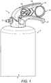
Figure 1 is a perspective view of a fire extinguisher incorporating a safety mechanism in accordance with the invention; -
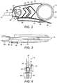
Figure 2 is a side elevation of the release member of the safety mechanism; -
Figure 3 is a top view of the release member ofFigure 2 ; -
Figure 4 is a front view of the release member ofFigure 2 -
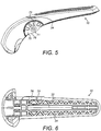
Figure 5 is a side view of the movable handle of the fire extinguisher ofFigure 1 ; -
Figure 6 is a bottom view of the handle ofFigure 5 ; -
Figure 7 is a perspective view of the fixed handle of the fire extinguisher ofFigure 1 -
Figure 8 is a front perspective view of the indicator member of the safety mechanism; -
Figure 9 is a rear perspective view of the indicator member ofFigure 8 ; -
Figure 10 is a side view of the indicator member ofFigure 8 ; and -
Figure 11 is a top view of the indicator member ofFigure 8 . - With reference to
Figure 1 , afire extinguisher 2 comprises ahead 4 having a ferrule 6 for the attachment of a hose (not shown). Thehead 4 comprises a fixedhandle 8 and amovable handle 10 which is pivotably mounted to the fixedhandle 8 about a pivot (not shown) in a known manner. As is known in the art, downward movement of themovable handle 10 presses on a actuating pin (not shown) which opens a valve to release fire suppressant, e.g. water, foam or powder through thehead 4 and ferrule 6. - To avoid inadvertent operation of the extinguisher, a
safety mechanism 14 is provided. Thesafety mechanism 14 comprises arelease member 16 and anindicator member 18. - The
release member 16 is moulded from a plastics material, e.g. polypropylene, and is elongate. It is received between the movable andfixed handles Figures 2 to 4 , therelease member 16 has a generallyplanar web 20 with a relativelynarrow flange 22 provided around its periphery, in particular along isupper edge 24, and a relativelywide flange 26 provided along itslower edge 28. Arib 30 projects downwardly from the relativelywide flange 26. - The relatively
narrow flange 22 is received within agroove 32 provided on thelower surface 34 of themovable handle 8, and therib 30 received in agroove 36 provided on an upwardly facingsurface 37 of the fixedhandle 10. The interengagement of theflange 22 ingroove 32 andrib 30 ingroove 36 provides lateral support for therelease member 16. - The
proximal end 38 of therelease member 16 is provided with acircular opening 40 through which a user may insert one or more fingers. Themiddle section 42 of theweb 20 is provided with arrow likeopenings 44 which indicate to the user the direction of operation of therelease member 16. - The
distal end 46 of therelease member 16 comprises aresilient clip 48 which in use engages around a post provided in themovable handle 8. - Also provided at the
distal end 46 of therelease member 16 is an L-section boss 50. Theboss 50 has a forwardly projectingflange 52 thedistal end 54 of which is provided anopening 56. Theopening 56 is generally circular in shape, but withstraight sides 58. Theopening 56 receives theindicator member 18, which is described with reference toFigures 8 to 10 . - The
indicator member 18 is of moulded from a plastics material such as polystyrene. In one embodiment, the material may be EDISTIR N1840 with 5 wt% regrind. It may be brightly coloured and may be fluorescent or phosphorescent. - It comprises a relatively thin, disk-shaped
head 60 and ashank 62 projecting from therear surface 64 of thehead 60. Although shown as circular, thehead 60 may of course have any convenient shape, for example polygonal. - The
front surface 66 of thehead 60 is provided with a recessed inscription 68 ("OK" in the illustrated embodiment) which will be seen by a user when theindicator member 18 is in situ. - The
rear surface 64 of thehead 60 is generally planar for engaging and covering acomplementary area 70 of themovable handle 8. As can be seen fromFigure 5 , thisarea 70 bears aninscription 72, in this embodiment "USED", so that when thearea 70 is exposed, the user will know that the extinguisher has been used. Of course some other wording may be used, for example "used" in other languages. Thatarea 70 also includes anopening 71 for receiving theshank 62 of theindicator member 18. - The
rear surface 64 of thehead 60 also comprises arib 74 which in use engages under a portion of thelower edge 76 of themovable handle 8 to assist in the orientation of theindicator member 18 so that theinscription 68 is the correct way up. - The
shank 62 is provided with aslot 78 at isdistal end 80, thereby defining tworesilient legs 82. Eachleg 82 is provided with abarbed tooth 84 at its distal end. The lateral surfaces 86 of eachleg 82 are formed as flat surfaces for engagement with thesides 58 of theopening 56 in the distal end of therelease member 16. Thesurfaces 86 stand proud of the surrounding surface, as can be seen most clearly fromFigure 11 . The upper andlower surfaces 88 of thelegs 82 are generally circular in section and of a diameter smaller than the circular sections of theopening 56. - The
shank 62 and has a taperingproximal section 90 and a transversely waistedintermediate section 92. Anopening 94 is provided through theintermediate section 92 to provide a well defined area of weakness in theshank 62. The dimensions of the waisting andopening 94 are chosen such that the shank can break in shear under an applied force of less than 100N. The maximum diameter of the proximal andintermediate sections opening 71 provided in thearea 70 of themovable handle 8 to allow theshank 62 to be received therein. - Installation and operation of the
safety mechanism 14 will now be described. - As a first step, the
release member 16 is inserted longitudinally into position between thehandles flange 22 and therib 30 provided on therelease member 16 and thegrooves handles release member 16 appropriately. Therelease member 16 is pushed into the space between thehandles clip 48 engages with the valve pin. In this position, theopening 56 at the distal end of therelease member 16 is aligned with theopening 71 provided in themovable handle 10. The relativelywide flange 26 of therelease member 16 generally follows the contour of and covers theupper surface 37 of the fixedhandle 8. - The
indicator member 18 can then be mounted. Theshank 62 of theindicator member 18 is pushed through theopening 71 in themovable handle 8 and the alignedopening 56 in therelease member 16. The resilience of thelegs 82 of theshank 62 allow thebarbed teeth 84 to deflect inwardly as theshank 62 is pressed in, and then spring back when theteeth 84 have passed through theopenings indicator member 18 from being withdrawn through the openings. The flat lateral surfaces 86 of thelegs 82 engage closely with thestraight sides 58 of theopening 56. This will help prevent twisting of theshank 62 as the release member is pulled out. - Proper orientation of the
head 60 is ensured by interengagement of therib 74 of thehead 60 and thelower edge 76 of themovable handle 8. - When the
indicator member 18 is so inserted, the user will see from the "OK"inscription 68 that the extinguisher is ready to use. Should the user inadvertently press on themovable handle 8, operation of the extinguisher is prevented by therelease member 16 which prevents themovable handle 8 moving towards the fixedhandle 10. Moreover, any small force acting to pull therelease member 16 rearwardly from between thehandles shank 62 of the indicator member and by theclip 48. - In the event of a fire, however, the user pulls the
release member 16 from between thehandles arrow openings 44. The pulling action causes the weakenedintermediate section 92 of theshank 62, which is within theopening 56 in therelease member 16, to shear, allowing therelease member 16 to be withdrawn. Therelease member 16 pulls thedistal end 80 of theshank 62 away with it so that it does not interfere with operation of the extinguisher. Thehead 60 of theindicator member 18 simply falls away, no longer being retained by itsshank 62. Theextinguisher 2 can then be used in the normal way. - After use, it will be clear to potential other users that the extinguisher has been used since the "USED"
inscription 72 is visible. - After the
extinguisher 2 has been recharged, anew safety mechanism 14 may be installed. The relativelyrobust release member 16 is not damaged in use and so may be re-used. However, anew indicator member 18 will have to be provided. The tapering of theproximal portion 90 of theshank 62 of theindicator member 18 means that the usedindicator member 18 cannot simply be pushed into theopening 71 in thehandle 8, as it will simply fall out. This would be undesirable since a user would then not be able to determine with certainty whether an extinguisher had been used or not. However, as theindicator member 18 is a moulding, it is relatively inexpensive to replace. - It will be understood that the above is a description of just one possible embodiment of the invention and that various modifications may be made to the embodiment without departing from the scope of the invention as defined by the following claims.
Claims (14)
- A fire extinguisher safety mechanism comprising:
an release member (16) configured for lengthwise insertion and withdrawal from between the handles (8, 10) of a fire extinguisher (2), said release member (16) having a proximal end (38) and a distal end (46), said proximal end (38) for gripping by a user; characterised in that:
said distal end (46) has an aperture (56); and in that said safety mechanism further comprises:an indicator member (18), said indicator member (18) having a head (60), a shank (62) projecting from said head (60) and having a distal end (80) with resilient retaining means,said indicator member (18) being configured to be mounted to said extinguisher (2), with its shank (62) passing through an aperture (71) in the head (4) of said extinguisher (2) and through said aperture (56) in said distal end (46) of said release member (16) so as to be retained relative to said release member (16) by said resilient retaining means and for preventing accidental withdrawal of said release member (16) from between the handles (8, 10). - A fire extinguisher safety mechanism as claimed in claim 1 wherein the head (60) of the indicator member (18) is relatively thin and disc like in shape.
- A fire extinguisher safety mechanism as claimed in any preceding claim wherein the indicator member (18) is configured to be received by a complementary area (70) provided on the extinguisher head (4), more particularly an area (70) on the movable handle (8) of the extinguisher (2), said area (70) optionally carrying an inscription (72) which becomes visible once the extinguisher (2) has been used.
- A fire extinguisher safety mechanism as claimed in any preceding claim wherein the shank (62) of the indicator member (18) is provided with one or more areas of weakness.
- A fire extinguisher safety mechanism as claimed in claim 4 wherein the area of weakness is provided by a through hole (94).
- A fire extinguisher safety mechanism as claimed in claim 5 wherein the hole (94) extends through a waisted area of an intermediate portion of said shank (62).
- A fire extinguisher safety mechanism as claimed in any preceding claim wherein a proximal portion (90) of the shank (62) tapers towards the distal end (80) of the shank (62).
- A fire extinguisher safety mechanism as claimed in any preceding claim wherein the resilient retaining means provided on the distal end (80) of the shank (62) comprises barbs (84) formed on the ends of flexible legs (82) formed by a slot (78) in the distal end (80) of the shank (62).
- A fire extinguisher safety mechanism as claimed in any preceding claim wherein the distal end (80) of the shank (62) has a profile which is at least in part complementary to the aperture (56) in the distal end (46) of the release member (16), for example wherein lateral surfaces of the flexible legs (82) are formed as flat surfaces to engage with flat surfaces of the aperture (56).
- A fire extinguisher safety mechanism as claimed in any preceding claim comprising alignment means to align the indicator member (18) in an appropriate orientation on the extinguisher (2), for example wherein a rear surface (64) of the head (60) of the indicator member (18) is provided with one or more ribs (74) which engage under a lower edge (76) of the handle (8) to which the indicator member (18) is mounted.
- A fire extinguisher safety mechanism as claimed in any preceding claim wherein the distal end (46) of the release member (16) is provided with a clip (48).
- A fire extinguisher safety mechanism as claimed in any preceding claim wherein the aperture (56) for receiving the shank (62) of the indicator member (18) is provided in a boss (50) provided at the distal end (46) of the release member (16), the boss (50) being offset from the main plane of the release member (16).
- A fire extinguisher safety mechanism as claimed in any preceding claim wherein the indicator member (18) and/or the release member (16) is brightly coloured, fluorescent, luminescent or phosphorescent.
- A fire extinguisher comprising a safety mechanism as claimed in any preceding claim.
Priority Applications (2)
| Application Number | Priority Date | Filing Date | Title |
|---|---|---|---|
| EP18188594.8A EP3421104B1 (en) | 2011-12-06 | 2012-12-04 | Fire extinguisher safety mechanism |
| PL12195557T PL2620183T3 (en) | 2011-12-06 | 2012-12-04 | Fire extinguisher safety mechanism |
Applications Claiming Priority (1)
| Application Number | Priority Date | Filing Date | Title |
|---|---|---|---|
| GB1120907.9A GB2497303B (en) | 2011-12-06 | 2011-12-06 | Fire extinguisher safety mechanism |
Related Child Applications (2)
| Application Number | Title | Priority Date | Filing Date |
|---|---|---|---|
| EP18188594.8A Division EP3421104B1 (en) | 2011-12-06 | 2012-12-04 | Fire extinguisher safety mechanism |
| EP18188594.8A Division-Into EP3421104B1 (en) | 2011-12-06 | 2012-12-04 | Fire extinguisher safety mechanism |
Publications (3)
| Publication Number | Publication Date |
|---|---|
| EP2620183A2 EP2620183A2 (en) | 2013-07-31 |
| EP2620183A3 EP2620183A3 (en) | 2015-07-01 |
| EP2620183B1 true EP2620183B1 (en) | 2019-09-18 |
Family
ID=45541243
Family Applications (2)
| Application Number | Title | Priority Date | Filing Date |
|---|---|---|---|
| EP18188594.8A Active EP3421104B1 (en) | 2011-12-06 | 2012-12-04 | Fire extinguisher safety mechanism |
| EP12195557.9A Active EP2620183B1 (en) | 2011-12-06 | 2012-12-04 | Fire extinguisher safety mechanism |
Family Applications Before (1)
| Application Number | Title | Priority Date | Filing Date |
|---|---|---|---|
| EP18188594.8A Active EP3421104B1 (en) | 2011-12-06 | 2012-12-04 | Fire extinguisher safety mechanism |
Country Status (3)
| Country | Link |
|---|---|
| EP (2) | EP3421104B1 (en) |
| GB (1) | GB2497303B (en) |
| PL (1) | PL2620183T3 (en) |
Families Citing this family (1)
| Publication number | Priority date | Publication date | Assignee | Title |
|---|---|---|---|---|
| US10105562B2 (en) | 2015-03-30 | 2018-10-23 | Utc Fire & Security Corporation | Hermetically sealed portable fire extinguisher with pressure indicator |
Family Cites Families (6)
| Publication number | Priority date | Publication date | Assignee | Title |
|---|---|---|---|---|
| JPS5223919Y2 (en) * | 1973-09-27 | 1977-05-31 | ||
| GB1566815A (en) * | 1978-04-18 | 1980-05-08 | Glover & Co Ltd T | Fire extinguishers |
| GB1567895A (en) * | 1978-04-26 | 1980-05-21 | Glover & Co Ltd T | Operating head for a fire extinguisher |
| DE3609499A1 (en) * | 1986-03-20 | 1987-09-24 | Werner Gmbh & Co Spezialfab | Fire extinguisher having a securing part |
| GB2322298A (en) * | 1997-02-20 | 1998-08-26 | Kidde Thorn Fire Protection Li | Discharge valve arrangement |
| JP2003091785A (en) * | 2001-09-15 | 2003-03-28 | Yoshio:Kk | Crime preventive spray tool with fire extinguishing function |
-
2011
- 2011-12-06 GB GB1120907.9A patent/GB2497303B/en active Active
-
2012
- 2012-12-04 EP EP18188594.8A patent/EP3421104B1/en active Active
- 2012-12-04 EP EP12195557.9A patent/EP2620183B1/en active Active
- 2012-12-04 PL PL12195557T patent/PL2620183T3/en unknown
Non-Patent Citations (1)
| Title |
|---|
| None * |
Also Published As
| Publication number | Publication date |
|---|---|
| EP3421104A1 (en) | 2019-01-02 |
| GB2497303B (en) | 2017-11-22 |
| GB2497303A (en) | 2013-06-12 |
| EP3421104B1 (en) | 2022-11-09 |
| GB201120907D0 (en) | 2012-01-18 |
| PL2620183T3 (en) | 2020-05-18 |
| EP2620183A2 (en) | 2013-07-31 |
| EP2620183A3 (en) | 2015-07-01 |
Similar Documents
| Publication | Publication Date | Title |
|---|---|---|
| ES2562002T5 (en) | Release prevention system for wall cabinets | |
| US10492578B2 (en) | Cross-country ski pole handle | |
| US4658481A (en) | Safety release pin for fire extinguishers | |
| EP3421104B1 (en) | Fire extinguisher safety mechanism | |
| KR20150143047A (en) | Percussion device for emergency evacuation | |
| US9185978B1 (en) | Drawer handle with releasable protective member | |
| WO2012063019A1 (en) | Inflation device with pressurised container and means for visual inspection of the presence of the container | |
| US3944269A (en) | Seal | |
| EP1503390A2 (en) | Call point for an alarm system | |
| EP1800585A2 (en) | Coupling device particularly for fixing the seat to a toilet bowl | |
| JP2011093573A (en) | Nozzle head for pump | |
| KR200483028Y1 (en) | Pedal Covers | |
| CN210575809U (en) | Double-indication-knife-type contact fuse link | |
| CN109523736B (en) | Fire alarm button device | |
| CN212260698U (en) | Fastener and bag and knee pad with same | |
| JP5376241B2 (en) | Pump nozzle head | |
| KR20070025302A (en) | Safety cutter knife | |
| JP6004969B2 (en) | A spout with anti-tampering function | |
| US20180264500A1 (en) | Sprinkler riser assembly | |
| CN219481361U (en) | Door and window breaking device for fire-fighting, fire-extinguishing and rescue | |
| US1944475A (en) | Snap hook | |
| CN205799595U (en) | One tears a velvet paw assembly | |
| JP7529586B2 (en) | Emergency escape device for construction machinery cabin | |
| US2148701A (en) | Sign-removing implement | |
| JP2005313957A (en) | Vertical pump container |
Legal Events
| Date | Code | Title | Description |
|---|---|---|---|
| PUAI | Public reference made under article 153(3) epc to a published international application that has entered the european phase |
Free format text: ORIGINAL CODE: 0009012 |
|
| AK | Designated contracting states |
Kind code of ref document: A2 Designated state(s): AL AT BE BG CH CY CZ DE DK EE ES FI FR GB GR HR HU IE IS IT LI LT LU LV MC MK MT NL NO PL PT RO RS SE SI SK SM TR |
|
| AX | Request for extension of the european patent |
Extension state: BA ME |
|
| PUAL | Search report despatched |
Free format text: ORIGINAL CODE: 0009013 |
|
| AK | Designated contracting states |
Kind code of ref document: A3 Designated state(s): AL AT BE BG CH CY CZ DE DK EE ES FI FR GB GR HR HU IE IS IT LI LT LU LV MC MK MT NL NO PL PT RO RS SE SI SK SM TR |
|
| AX | Request for extension of the european patent |
Extension state: BA ME |
|
| RIC1 | Information provided on ipc code assigned before grant |
Ipc: A62C 13/76 20060101AFI20150527BHEP |
|
| 17P | Request for examination filed |
Effective date: 20151209 |
|
| RBV | Designated contracting states (corrected) |
Designated state(s): AL AT BE BG CH CY CZ DE DK EE ES FI FR GB GR HR HU IE IS IT LI LT LU LV MC MK MT NL NO PL PT RO RS SE SI SK SM TR |
|
| GRAP | Despatch of communication of intention to grant a patent |
Free format text: ORIGINAL CODE: EPIDOSNIGR1 |
|
| STAA | Information on the status of an ep patent application or granted ep patent |
Free format text: STATUS: GRANT OF PATENT IS INTENDED |
|
| INTG | Intention to grant announced |
Effective date: 20181218 |
|
| GRAS | Grant fee paid |
Free format text: ORIGINAL CODE: EPIDOSNIGR3 |
|
| GRAA | (expected) grant |
Free format text: ORIGINAL CODE: 0009210 |
|
| STAA | Information on the status of an ep patent application or granted ep patent |
Free format text: STATUS: THE PATENT HAS BEEN GRANTED |
|
| AK | Designated contracting states |
Kind code of ref document: B1 Designated state(s): AL AT BE BG CH CY CZ DE DK EE ES FI FR GB GR HR HU IE IS IT LI LT LU LV MC MK MT NL NO PL PT RO RS SE SI SK SM TR |
|
| REG | Reference to a national code |
Ref country code: GB Ref legal event code: FG4D |
|
| REG | Reference to a national code |
Ref country code: CH Ref legal event code: EP |
|
| REG | Reference to a national code |
Ref country code: DE Ref legal event code: R096 Ref document number: 602012064065 Country of ref document: DE |
|
| REG | Reference to a national code |
Ref country code: AT Ref legal event code: REF Ref document number: 1180614 Country of ref document: AT Kind code of ref document: T Effective date: 20191015 |
|
| REG | Reference to a national code |
Ref country code: IE Ref legal event code: FG4D |
|
| REG | Reference to a national code |
Ref country code: NL Ref legal event code: MP Effective date: 20190918 |
|
| PG25 | Lapsed in a contracting state [announced via postgrant information from national office to epo] |
Ref country code: BG Free format text: LAPSE BECAUSE OF FAILURE TO SUBMIT A TRANSLATION OF THE DESCRIPTION OR TO PAY THE FEE WITHIN THE PRESCRIBED TIME-LIMIT Effective date: 20191218 Ref country code: SE Free format text: LAPSE BECAUSE OF FAILURE TO SUBMIT A TRANSLATION OF THE DESCRIPTION OR TO PAY THE FEE WITHIN THE PRESCRIBED TIME-LIMIT Effective date: 20190918 Ref country code: LT Free format text: LAPSE BECAUSE OF FAILURE TO SUBMIT A TRANSLATION OF THE DESCRIPTION OR TO PAY THE FEE WITHIN THE PRESCRIBED TIME-LIMIT Effective date: 20190918 Ref country code: HR Free format text: LAPSE BECAUSE OF FAILURE TO SUBMIT A TRANSLATION OF THE DESCRIPTION OR TO PAY THE FEE WITHIN THE PRESCRIBED TIME-LIMIT Effective date: 20190918 Ref country code: FI Free format text: LAPSE BECAUSE OF FAILURE TO SUBMIT A TRANSLATION OF THE DESCRIPTION OR TO PAY THE FEE WITHIN THE PRESCRIBED TIME-LIMIT Effective date: 20190918 Ref country code: NO Free format text: LAPSE BECAUSE OF FAILURE TO SUBMIT A TRANSLATION OF THE DESCRIPTION OR TO PAY THE FEE WITHIN THE PRESCRIBED TIME-LIMIT Effective date: 20191218 |
|
| REG | Reference to a national code |
Ref country code: LT Ref legal event code: MG4D |
|
| PG25 | Lapsed in a contracting state [announced via postgrant information from national office to epo] |
Ref country code: LV Free format text: LAPSE BECAUSE OF FAILURE TO SUBMIT A TRANSLATION OF THE DESCRIPTION OR TO PAY THE FEE WITHIN THE PRESCRIBED TIME-LIMIT Effective date: 20190918 Ref country code: AL Free format text: LAPSE BECAUSE OF FAILURE TO SUBMIT A TRANSLATION OF THE DESCRIPTION OR TO PAY THE FEE WITHIN THE PRESCRIBED TIME-LIMIT Effective date: 20190918 Ref country code: GR Free format text: LAPSE BECAUSE OF FAILURE TO SUBMIT A TRANSLATION OF THE DESCRIPTION OR TO PAY THE FEE WITHIN THE PRESCRIBED TIME-LIMIT Effective date: 20191219 Ref country code: RS Free format text: LAPSE BECAUSE OF FAILURE TO SUBMIT A TRANSLATION OF THE DESCRIPTION OR TO PAY THE FEE WITHIN THE PRESCRIBED TIME-LIMIT Effective date: 20190918 |
|
| REG | Reference to a national code |
Ref country code: AT Ref legal event code: MK05 Ref document number: 1180614 Country of ref document: AT Kind code of ref document: T Effective date: 20190918 |
|
| PG25 | Lapsed in a contracting state [announced via postgrant information from national office to epo] |
Ref country code: ES Free format text: LAPSE BECAUSE OF FAILURE TO SUBMIT A TRANSLATION OF THE DESCRIPTION OR TO PAY THE FEE WITHIN THE PRESCRIBED TIME-LIMIT Effective date: 20190918 Ref country code: AT Free format text: LAPSE BECAUSE OF FAILURE TO SUBMIT A TRANSLATION OF THE DESCRIPTION OR TO PAY THE FEE WITHIN THE PRESCRIBED TIME-LIMIT Effective date: 20190918 Ref country code: RO Free format text: LAPSE BECAUSE OF FAILURE TO SUBMIT A TRANSLATION OF THE DESCRIPTION OR TO PAY THE FEE WITHIN THE PRESCRIBED TIME-LIMIT Effective date: 20190918 Ref country code: NL Free format text: LAPSE BECAUSE OF FAILURE TO SUBMIT A TRANSLATION OF THE DESCRIPTION OR TO PAY THE FEE WITHIN THE PRESCRIBED TIME-LIMIT Effective date: 20190918 Ref country code: EE Free format text: LAPSE BECAUSE OF FAILURE TO SUBMIT A TRANSLATION OF THE DESCRIPTION OR TO PAY THE FEE WITHIN THE PRESCRIBED TIME-LIMIT Effective date: 20190918 Ref country code: IT Free format text: LAPSE BECAUSE OF FAILURE TO SUBMIT A TRANSLATION OF THE DESCRIPTION OR TO PAY THE FEE WITHIN THE PRESCRIBED TIME-LIMIT Effective date: 20190918 Ref country code: PT Free format text: LAPSE BECAUSE OF FAILURE TO SUBMIT A TRANSLATION OF THE DESCRIPTION OR TO PAY THE FEE WITHIN THE PRESCRIBED TIME-LIMIT Effective date: 20200120 |
|
| PG25 | Lapsed in a contracting state [announced via postgrant information from national office to epo] |
Ref country code: SM Free format text: LAPSE BECAUSE OF FAILURE TO SUBMIT A TRANSLATION OF THE DESCRIPTION OR TO PAY THE FEE WITHIN THE PRESCRIBED TIME-LIMIT Effective date: 20190918 Ref country code: IS Free format text: LAPSE BECAUSE OF FAILURE TO SUBMIT A TRANSLATION OF THE DESCRIPTION OR TO PAY THE FEE WITHIN THE PRESCRIBED TIME-LIMIT Effective date: 20200224 Ref country code: CZ Free format text: LAPSE BECAUSE OF FAILURE TO SUBMIT A TRANSLATION OF THE DESCRIPTION OR TO PAY THE FEE WITHIN THE PRESCRIBED TIME-LIMIT Effective date: 20190918 Ref country code: SK Free format text: LAPSE BECAUSE OF FAILURE TO SUBMIT A TRANSLATION OF THE DESCRIPTION OR TO PAY THE FEE WITHIN THE PRESCRIBED TIME-LIMIT Effective date: 20190918 |
|
| REG | Reference to a national code |
Ref country code: DE Ref legal event code: R097 Ref document number: 602012064065 Country of ref document: DE |
|
| REG | Reference to a national code |
Ref country code: DE Ref legal event code: R119 Ref document number: 602012064065 Country of ref document: DE |
|
| PLBE | No opposition filed within time limit |
Free format text: ORIGINAL CODE: 0009261 |
|
| STAA | Information on the status of an ep patent application or granted ep patent |
Free format text: STATUS: NO OPPOSITION FILED WITHIN TIME LIMIT |
|
| PG2D | Information on lapse in contracting state deleted |
Ref country code: IS |
|
| PG25 | Lapsed in a contracting state [announced via postgrant information from national office to epo] |
Ref country code: DK Free format text: LAPSE BECAUSE OF FAILURE TO SUBMIT A TRANSLATION OF THE DESCRIPTION OR TO PAY THE FEE WITHIN THE PRESCRIBED TIME-LIMIT Effective date: 20190918 Ref country code: IS Free format text: LAPSE BECAUSE OF FAILURE TO SUBMIT A TRANSLATION OF THE DESCRIPTION OR TO PAY THE FEE WITHIN THE PRESCRIBED TIME-LIMIT Effective date: 20200119 |
|
| REG | Reference to a national code |
Ref country code: CH Ref legal event code: PL |
|
| 26N | No opposition filed |
Effective date: 20200619 |
|
| REG | Reference to a national code |
Ref country code: BE Ref legal event code: MM Effective date: 20191231 |
|
| PG25 | Lapsed in a contracting state [announced via postgrant information from national office to epo] |
Ref country code: MC Free format text: LAPSE BECAUSE OF FAILURE TO SUBMIT A TRANSLATION OF THE DESCRIPTION OR TO PAY THE FEE WITHIN THE PRESCRIBED TIME-LIMIT Effective date: 20190918 Ref country code: SI Free format text: LAPSE BECAUSE OF FAILURE TO SUBMIT A TRANSLATION OF THE DESCRIPTION OR TO PAY THE FEE WITHIN THE PRESCRIBED TIME-LIMIT Effective date: 20190918 |
|
| GBPC | Gb: european patent ceased through non-payment of renewal fee |
Effective date: 20191218 |
|
| PG25 | Lapsed in a contracting state [announced via postgrant information from national office to epo] |
Ref country code: DE Free format text: LAPSE BECAUSE OF NON-PAYMENT OF DUE FEES Effective date: 20200701 Ref country code: FR Free format text: LAPSE BECAUSE OF NON-PAYMENT OF DUE FEES Effective date: 20191231 Ref country code: IE Free format text: LAPSE BECAUSE OF NON-PAYMENT OF DUE FEES Effective date: 20191204 Ref country code: GB Free format text: LAPSE BECAUSE OF NON-PAYMENT OF DUE FEES Effective date: 20191218 Ref country code: LU Free format text: LAPSE BECAUSE OF NON-PAYMENT OF DUE FEES Effective date: 20191204 |
|
| PG25 | Lapsed in a contracting state [announced via postgrant information from national office to epo] |
Ref country code: CH Free format text: LAPSE BECAUSE OF NON-PAYMENT OF DUE FEES Effective date: 20191231 Ref country code: LI Free format text: LAPSE BECAUSE OF NON-PAYMENT OF DUE FEES Effective date: 20191231 Ref country code: BE Free format text: LAPSE BECAUSE OF NON-PAYMENT OF DUE FEES Effective date: 20191231 |
|
| PG25 | Lapsed in a contracting state [announced via postgrant information from national office to epo] |
Ref country code: CY Free format text: LAPSE BECAUSE OF FAILURE TO SUBMIT A TRANSLATION OF THE DESCRIPTION OR TO PAY THE FEE WITHIN THE PRESCRIBED TIME-LIMIT Effective date: 20190918 |
|
| PG25 | Lapsed in a contracting state [announced via postgrant information from national office to epo] |
Ref country code: HU Free format text: LAPSE BECAUSE OF FAILURE TO SUBMIT A TRANSLATION OF THE DESCRIPTION OR TO PAY THE FEE WITHIN THE PRESCRIBED TIME-LIMIT; INVALID AB INITIO Effective date: 20121204 Ref country code: MT Free format text: LAPSE BECAUSE OF FAILURE TO SUBMIT A TRANSLATION OF THE DESCRIPTION OR TO PAY THE FEE WITHIN THE PRESCRIBED TIME-LIMIT Effective date: 20190918 |
|
| PG25 | Lapsed in a contracting state [announced via postgrant information from national office to epo] |
Ref country code: TR Free format text: LAPSE BECAUSE OF FAILURE TO SUBMIT A TRANSLATION OF THE DESCRIPTION OR TO PAY THE FEE WITHIN THE PRESCRIBED TIME-LIMIT Effective date: 20190918 |
|
| PG25 | Lapsed in a contracting state [announced via postgrant information from national office to epo] |
Ref country code: MK Free format text: LAPSE BECAUSE OF FAILURE TO SUBMIT A TRANSLATION OF THE DESCRIPTION OR TO PAY THE FEE WITHIN THE PRESCRIBED TIME-LIMIT Effective date: 20190918 |
|
| PGFP | Annual fee paid to national office [announced via postgrant information from national office to epo] |
Ref country code: PL Payment date: 20251124 Year of fee payment: 14 |