EP2620112A1 - Dispositif d'ancrage d'os - Google Patents
Dispositif d'ancrage d'os Download PDFInfo
- Publication number
- EP2620112A1 EP2620112A1 EP12153154.5A EP12153154A EP2620112A1 EP 2620112 A1 EP2620112 A1 EP 2620112A1 EP 12153154 A EP12153154 A EP 12153154A EP 2620112 A1 EP2620112 A1 EP 2620112A1
- Authority
- EP
- European Patent Office
- Prior art keywords
- pressure member
- bone anchoring
- receiving part
- head
- anchoring device
- Prior art date
- Legal status (The legal status is an assumption and is not a legal conclusion. Google has not performed a legal analysis and makes no representation as to the accuracy of the status listed.)
- Granted
Links
Images


Classifications
-
- A—HUMAN NECESSITIES
- A61—MEDICAL OR VETERINARY SCIENCE; HYGIENE
- A61B—DIAGNOSIS; SURGERY; IDENTIFICATION
- A61B17/00—Surgical instruments, devices or methods, e.g. tourniquets
- A61B17/56—Surgical instruments or methods for treatment of bones or joints; Devices specially adapted therefor
- A61B17/58—Surgical instruments or methods for treatment of bones or joints; Devices specially adapted therefor for osteosynthesis, e.g. bone plates, screws, setting implements or the like
- A61B17/68—Internal fixation devices, including fasteners and spinal fixators, even if a part thereof projects from the skin
- A61B17/70—Spinal positioners or stabilisers ; Bone stabilisers comprising fluid filler in an implant
- A61B17/7001—Screws or hooks combined with longitudinal elements which do not contact vertebrae
- A61B17/7002—Longitudinal elements, e.g. rods
-
- A—HUMAN NECESSITIES
- A61—MEDICAL OR VETERINARY SCIENCE; HYGIENE
- A61B—DIAGNOSIS; SURGERY; IDENTIFICATION
- A61B17/00—Surgical instruments, devices or methods, e.g. tourniquets
- A61B17/56—Surgical instruments or methods for treatment of bones or joints; Devices specially adapted therefor
- A61B17/58—Surgical instruments or methods for treatment of bones or joints; Devices specially adapted therefor for osteosynthesis, e.g. bone plates, screws, setting implements or the like
- A61B17/68—Internal fixation devices, including fasteners and spinal fixators, even if a part thereof projects from the skin
- A61B17/70—Spinal positioners or stabilisers ; Bone stabilisers comprising fluid filler in an implant
- A61B17/7001—Screws or hooks combined with longitudinal elements which do not contact vertebrae
- A61B17/7032—Screws or hooks with U-shaped head or back through which longitudinal rods pass
- A61B17/7034—Screws or hooks with U-shaped head or back through which longitudinal rods pass characterised by a lateral opening
-
- A—HUMAN NECESSITIES
- A61—MEDICAL OR VETERINARY SCIENCE; HYGIENE
- A61B—DIAGNOSIS; SURGERY; IDENTIFICATION
- A61B17/00—Surgical instruments, devices or methods, e.g. tourniquets
- A61B17/56—Surgical instruments or methods for treatment of bones or joints; Devices specially adapted therefor
- A61B17/58—Surgical instruments or methods for treatment of bones or joints; Devices specially adapted therefor for osteosynthesis, e.g. bone plates, screws, setting implements or the like
- A61B17/68—Internal fixation devices, including fasteners and spinal fixators, even if a part thereof projects from the skin
- A61B17/70—Spinal positioners or stabilisers ; Bone stabilisers comprising fluid filler in an implant
- A61B17/7001—Screws or hooks combined with longitudinal elements which do not contact vertebrae
- A61B17/7035—Screws or hooks, wherein a rod-clamping part and a bone-anchoring part can pivot relative to each other
- A61B17/7037—Screws or hooks, wherein a rod-clamping part and a bone-anchoring part can pivot relative to each other wherein pivoting is blocked when the rod is clamped
-
- A—HUMAN NECESSITIES
- A61—MEDICAL OR VETERINARY SCIENCE; HYGIENE
- A61B—DIAGNOSIS; SURGERY; IDENTIFICATION
- A61B17/00—Surgical instruments, devices or methods, e.g. tourniquets
- A61B17/56—Surgical instruments or methods for treatment of bones or joints; Devices specially adapted therefor
- A61B17/58—Surgical instruments or methods for treatment of bones or joints; Devices specially adapted therefor for osteosynthesis, e.g. bone plates, screws, setting implements or the like
- A61B17/68—Internal fixation devices, including fasteners and spinal fixators, even if a part thereof projects from the skin
- A61B17/70—Spinal positioners or stabilisers ; Bone stabilisers comprising fluid filler in an implant
- A61B17/7049—Connectors, not bearing on the vertebrae, for linking longitudinal elements together
-
- A—HUMAN NECESSITIES
- A61—MEDICAL OR VETERINARY SCIENCE; HYGIENE
- A61B—DIAGNOSIS; SURGERY; IDENTIFICATION
- A61B17/00—Surgical instruments, devices or methods, e.g. tourniquets
- A61B17/56—Surgical instruments or methods for treatment of bones or joints; Devices specially adapted therefor
- A61B17/58—Surgical instruments or methods for treatment of bones or joints; Devices specially adapted therefor for osteosynthesis, e.g. bone plates, screws, setting implements or the like
- A61B17/68—Internal fixation devices, including fasteners and spinal fixators, even if a part thereof projects from the skin
- A61B17/70—Spinal positioners or stabilisers ; Bone stabilisers comprising fluid filler in an implant
- A61B17/7074—Tools specially adapted for spinal fixation operations other than for bone removal or filler handling
- A61B17/7076—Tools specially adapted for spinal fixation operations other than for bone removal or filler handling for driving, positioning or assembling spinal clamps or bone anchors specially adapted for spinal fixation
- A61B17/7082—Tools specially adapted for spinal fixation operations other than for bone removal or filler handling for driving, positioning or assembling spinal clamps or bone anchors specially adapted for spinal fixation for driving, i.e. rotating, screws or screw parts specially adapted for spinal fixation, e.g. for driving polyaxial or tulip-headed screws
-
- A—HUMAN NECESSITIES
- A61—MEDICAL OR VETERINARY SCIENCE; HYGIENE
- A61B—DIAGNOSIS; SURGERY; IDENTIFICATION
- A61B17/00—Surgical instruments, devices or methods, e.g. tourniquets
- A61B17/56—Surgical instruments or methods for treatment of bones or joints; Devices specially adapted therefor
- A61B17/58—Surgical instruments or methods for treatment of bones or joints; Devices specially adapted therefor for osteosynthesis, e.g. bone plates, screws, setting implements or the like
- A61B17/68—Internal fixation devices, including fasteners and spinal fixators, even if a part thereof projects from the skin
- A61B17/84—Fasteners therefor or fasteners being internal fixation devices
- A61B17/86—Pins or screws or threaded wires; nuts therefor
- A61B17/8605—Heads, i.e. proximal ends projecting from bone
-
- A—HUMAN NECESSITIES
- A61—MEDICAL OR VETERINARY SCIENCE; HYGIENE
- A61B—DIAGNOSIS; SURGERY; IDENTIFICATION
- A61B17/00—Surgical instruments, devices or methods, e.g. tourniquets
- A61B2017/00526—Methods of manufacturing
-
- F—MECHANICAL ENGINEERING; LIGHTING; HEATING; WEAPONS; BLASTING
- F04—POSITIVE - DISPLACEMENT MACHINES FOR LIQUIDS; PUMPS FOR LIQUIDS OR ELASTIC FLUIDS
- F04C—ROTARY-PISTON, OR OSCILLATING-PISTON, POSITIVE-DISPLACEMENT MACHINES FOR LIQUIDS; ROTARY-PISTON, OR OSCILLATING-PISTON, POSITIVE-DISPLACEMENT PUMPS
- F04C2270/00—Control; Monitoring or safety arrangements
- F04C2270/04—Force
- F04C2270/041—Controlled or regulated
Definitions
- the invention relates to a bone anchoring device comprising a bone anchoring element having a head and a shaft for anchoring in the bone, a receiving part for coupling the bone anchoring element to a rod, the receiving part comprising an accommodation space for accommodating the head and a bore being in communication with the accommodation space, the bore having a bore axis, a pressure member configured to move in the bore and comprising a first surface for engaging the head and a second surface on which the rod acts, wherein the pressure member is configured to assume a first position in which it exerts a preload onto the head that results from friction between the first surface and the head to enable the shaft to be maintained in a desired angular position before locking the head in the receiving part, and a second position in which the head is locked with respect to the receiving part, and wherein the first position is obtained by moving the pressure member by the action of a predefined force acting onto the pressure member in an axial direction and wherein the pressure member is maintained in the first position by interaction with the receiving part and can be released from the first position through
- US 2007/0118123 A1 describes a polyaxial bone anchor with increased angulation.
- the 20 polyaxial bone anchor has a locking element shaped and configured to allow an anchoring member e.g. a screw or hook to polyaxially rotate at large angles about a central axis of the bone anchor before compression locking the anchoring member within an anchor head.
- an anchoring member e.g. a screw or hook
- US 7,604,656 B2 describes an apparatus comprising a fastener, a housing having a passage, and a spacer received in the passage and engageable with the fastener, wherein pin members retain the spacer and the fastener in the housing and wherein an end portion of the pin members has a tapered surface by which the spacer is urged axially toward the fastener when the pin member is inserted through the housing.
- the pin members also apply an axial force to the spacer to prevent relative movement between the spacer and the housing when the rod is disengaged from the spacer and the spacer engages the fastener.
- the pin members hold the spacer in frictional engagement with the fastener.
- the mechanism to frictionally maintain the position of the head before locking is free from any spring members or portions.
- the polyaxial bone anchoring device has few parts, which are of simple design. According to an embodiment, for achieving the preload onto the head no further parts are required due to the interference fit connection. Referring to the interference fit connection the radial forces, i.e. in a 90° angle to the longitudinal axis of the receiving part, result from the elastic deformation of the material.
- the bone anchoring device can be manufactured easily and cost-effectively to. Furthermore, existing receiving parts can be used without having to redesign their shape. Only the pressure members have to be adapted in that an interference fit between an outer diameter of the pressure member and an inner diameter of the receiving part is achieved.
- the amount of preload exerted onto the head by the pressure member can be exactly predefined in a simple manner during assembly by adjusting the externally applied axial force.
- the preload onto the head generated in this way is reproducible..
- the polyaxial bone anchoring device is provided to the surgeon in a pre-assembled manner, in which the pressure member is axially and rotationally fixed by friction in the receiving part to such an extent that it can not fall out or be rotated out of its aligned position. This allows a safe handling by the surgeon.
- a repeatable friction fit e.g. interference fit connection is achieved.
- the polyaxial bone anchoring device provides for an enlarged pivot angulation of the bone screw by attaching a sleeve-like insert while equally providing high efficiency of fixation.
- the pivot angle of the bone anchoring element relative to the receiving part is equal to or greater than 45° measured from the straight position. This renders the bone anchoring device particularly suitable for the application of lateral mass fixation for example in the cervical spine.
- the locking mechanism for locking the bone anchoring element and the sleeve-like insert piece provides a high clamping force on a small surface. Therefore, the locking mechanism is efficient.
- a polyaxial bone anchoring device comprises a bone anchoring element 1 in the form of a bone screw having a threaded shaft 2 and a head 3.
- the head 3 typically has a spherically-shaped outer surface portion 3 a and a recess 3b at its free end for engagement with a tool, e.g. a driver.
- the head 3 is held in a receiving part 4 that couples the bone anchoring element 1 to a stabilization rod 100.
- a sleeve-like insert piece 5 providing a seat for the head 3 and a pressure member 6 for exerting pressure onto the head 3 of the bone anchoring element 1 are arranged.
- a fixation element in the form of a fixation screw 7 is provided for securing and fixing the rod 100 in the receiving part 4.
- a bone anchoring device without the sleeve-like insert piece 5 is also possible. In that case, the seat for the head 3 is provided at the receiving part 4 directly.
- the receiving part 4 has a top end 4a and a bottom end 4b, a central axis C and a coaxial bore 41 extending from the top end 4a in the direction of the bottom end 4b.
- Adjacent to the top end 4a an U-shaped recess 42 is provided that forms a channel for receiving the rod 100.
- two free legs are formed, which are provided with an internal thread 43 cooperating with the outer thread of the fixation screw 7 in an assembled state (see Fig. 2 ).
- the coaxial bore 41 opens into an accommodation space 8 provided in the lower part of the receiving part 4.
- the accommodation space 8 has a lower opening 45 at the bottom end 4b of the receiving part 4.
- the accommodation space 8 further comprises a seat portion 46 near the bottom end 4b of the receiving part 4, in which the sleeve-like insert piece 5 is seated.
- the seat portion 46 has a spherical shape in order to provide a socket for a ball and socket joint that is formed by the sleeve-insert piece 5 and the receiving part 4. It should be noted that the seat portion 46 can also be tapered or can have another shape that can be used to realize a ball and a socket joint.
- the inner diameter of the lower opening 45 is smaller than the inner diameter of the accommodation space 8. It shall be noted that the inner diameter of the coaxial bore 41 does not need to be constant between the top end 4a and the accommodation space 8. It may have different portions with different diameters.
- two opposed recesses 47a, 47b are provided in the inner wall of the coaxial bore 41 and the accommodation space 8.
- the recesses 47a, 47b are aligned with the U-shaped recess 42. They extend from the bottom of the U-shaped recess 42 into the accommodation space 8.
- the size of the recesses 47a, 47b is such that the sleeve-like insert piece 5 can be introduced from the top end in a 90° tilted position, i.e. the width of the recesses 47a, 47b is greater than the height of the sleeve-like insert piece 5 in its axial direction.
- the recesses 47a, 47b extend into the accommodation space 8 to such an extent, that tilting of the sleeve-like insert piece 5 into the seat 46 is possible.
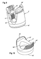
- the pressure member 6 is shown in particular in Figs. 5a to 5e .
- the pressure member 6 is substantially cylindrical with an outer diameter that allows the pressure member 6 to be moved within the coaxial bore 41 and the accommodation space 8, e.g. by means of a tool.
- an outer diameter of the pressure member 6 is slightly larger than an inner diameter of the coaxial bore 41 to achieve an interference fit. or press fit connection between the inner surface of the coaxial bore 41 and the outer surface 65 of the pressure member 6. It is also possible that only parts of the mentioned surfaces form the interference fit.
- the pressure member 6 has an upper end 6a and a lower edge 6b.
- the pressure member 6 Adjacent its lower edge 6b, the pressure member 6 comprises a recess 61 with a spherical shape that matches the shape of the outer spherical surface portion 3a of the head 3. At the upper end 6a, the pressure member 6 comprises a cylindrical recess 63 for receiving the rod 100 therein. Furthermore, the pressure member 6 has a coaxial bore 64 for allowing access to the screw head 3 with a tool in an assembled state. By the coaxial bore 64 and the cylindrical recess 63 two legs are formed facing the top end 4a. The coaxial bore 64 is also configured to allow a portion of the head 3 to extend therethrough, when the bone anchoring element is in a pivoted condition.
- the sleeve-like insert piece 5 is shown in particular in Figs. 6a-6d .
- the sleeve-like insert piece 5 comprises an upper edge 5a and a lower edge 5b. Between the upper edge 5a and the lower edge 5b, the sleeve-like insert piece 5 comprises a spherical-shaped outer surface portion 51.
- the largest outer diameter of the sleeve-like insert piece 5 is greater than the inner diameter of the lower opening 45 of the receiving part 4. Hence, the sleeve-like insert piece 5 can not escape through the lower opening 45, when it is seated in the receiving part 4.
- the dimension of the outer spherical surface portion 51 corresponds to the spherical-shaped seat portion 46 of the receiving part 4 in such a way that the sleeve-like insert piece 5 can pivot and rotate in the receiving part 4, when it is seated in the seat portion 46.
- the sleeve-like insert piece 5 rests in the seat portion 46 such that its centre axis 5c is coaxial with the centre axis C of the receiving part 4, the lower edge 5b projects out of the lower opening 45.
- the sleeve-like insert piece 5 is pivoted in the receiving part 4, at least a portion of the lower edge 5b still projects out of the lower opening 45.
- the sleeve-like insert piece 5 is hollow and comprises a central inner portion 52 that is spherically-shaped with a radius corresponding to the radius of the spherically-shaped outer surface portion 3a of the head 3 of the bone anchoring element 1.
- the lower end of the central portion 52 forms a shoulder 53.
- the inner diameter of the shoulder 53 is smaller than the largest outer diameter of the spherical head 3 so that the head 3 can rotate and pivot in the central spherical portion 52 of the sleeve-like insert piece 5 similar to a ball and socket joint.
- a tapered portion 54 is provided that tapers outwards to allow angulation of the bone anchoring element 1 until the shaft 2 comes into contact with the lower edge 5b.
- a tapered portion 55 is provided, which tapers outwards.
- the inner diameter of the tapered portion 55 and of the transition between the tapered portion 55 and the spherical central portion 52 is always greater than the largest outer diameter of the head 3, so that the head 3 can be inserted from the upper edge 5a into the sleeve-like insert piece 5.
- a chamfered portion 56 is provided that may serve as a stop for the pressure member 6.
- the center points of the spherical central portion 52 and the outer spherical portion 51 may be offset in such a way that the centre point of the inner central spherical portion 52 is shifted in the direction towards the bottom end 4b.
- the range of angulation for the bone anchoring element 1 can be further increased.
- the height of the sleeve-like insert piece 5 in axial direction is less than the height of the head 3 in axial direction such that, when the head 3 is inserted into the sleeve-like insert piece 5, still a portion of the spherical outer surface 3a of the head 3 projects from the upper edge 5a of the sleeve-like insert piece 5 as can be seen from Fig. 3 a.
- the sleeve-like insert piece 5 and the anchoring element 1 are independently pivotable when the shaft 2 of the anchoring element 1 and the lower edge 5b of the sleeve-like insert piece 5 are out of contact.
- the shaft 2 of the bone anchoring element 1 is pivoted and engages the lower edge 5b of the sleeve-like insert piece 5, further pivoting of the bone anchoring element 1 causes the sleeve-like insert piece 5 to pivot together with the bone anchoring element 1.
- the pressure member 6 is in contact with the head 3, there is a gap between the pressure member 6 and the sleeve-like insert piece 5.
- a force F which is provided from above in the figures divides in frictional resistance (indicated by the two horizontal arrows) and preload force (indicated by the small arrows in Fig. 3b ) which holds the head with respect to the receiving part 4 in a desired angular orientation by friction.
- the frictional resistance results from the interference fit connection between the pressure member 6 and the receiving part 4, wherein the outer diameter of at least one portion of the pressure member 6 is slightly larger than the inner diameter of the corresponding portion of the receiving part 4.
- the preload force acting on the head 4 leads to a small elastic preload of the whole system.
- the steps of pre-assembling the bone anchoring device according to the first embodiment are shown with respect to Figs. 7 a) to 7 h ).
- the bone anchoring device according to the first embodiment may be pre-assembled in such a way that first the sleeve-like insert piece 5 is tilted by 90° and inserted into the receiving part 4 at the position of the U-shaped recess 42 as can be seen from Figs. 7a and 7b . As shown in Fig. 7b the sleeve-like insert piece 5 is moved downwards into the accommodation space 8.
- the sleeve-like insert piece 5 Since the outer diameter of the sleeve-like insert piece 5 is larger than the inner diameter the lower opening 45 of the receiving part 4, the sleeve-like insert piece 5 can not escape through the lower edge of the lower opening 45. Then, as shown in Figs. 7c and 7d the sleeve-like insert piece 5 is tilted so that it fmally is seated in the seat portion 46, as shown in Fig. 7d .
- the bone anchoring element 1 is inserted from the top end 4a of the receiving part 4 until the outer surface portion 3a of the head 3 engages the seat portion 52 of the sleeve-like insert piece 5 as can be seen from Figs. 7e and 7f .
- the pressure member 6 is inserted from the top end 4a as can be seen from Fig. 7g by applying a predefined force from the top as indicated by the arrow in Fig. 7h .
- the pressure member 6 is arranged in an aligned position, in which the cylindrical recess 63 is aligned with the U-shaped recess 42 of the receiving part 4 for receiving the rod 100.
- Dependent on the degree of the interference fit connection it may be necessary to use a tool for pushing down the pressure member 6 into the receiving part 4.
- the predefined force from above may be generated manually or by a tool, for example and may be constant and/or force- or path-controlled.
- the bone anchoring device as a whole or in parts is made of a bio-compatible material, such as a bio-compatible metal, for example titanium, stainless steel, bio-compatible alloy, such as nitinol, or of bio-compatible plastic material, such as, for example, polyetheretherketone (PEEK).
- a bio-compatible material such as a bio-compatible metal, for example titanium, stainless steel, bio-compatible alloy, such as nitinol, or of bio-compatible plastic material, such as, for example, polyetheretherketone (PEEK).
- Figs. 8a to 10 show a second embodiment of the bone anchoring device. Parts and portions, which are the same or similar to those of the first embodiment, are designated with the same reference numerals and the description thereof is not repeated.
- the bone anchoring device according to the second embodiment differs from the bone anchoring device of the first embodiment by the construction of the outer surface 65' of the pressure member 6' and the corresponding surface of the coaxial bore 41' of the receiving part 4'. All other parts are identical to those of the first embodiment.
- the surface of the coaxial bore 41' is structured, for example roughened or fluted or grooved or ridged.
- the outer surface of the pressure member 6' is also structured, such as roughened or fluted or grooved or ridged.
- the surface interaction of the two structured surfaces prevents the pressure member 6' from moving backwards towards the first end 4a'. Therefore, the holding function of the interference fit connection is further increased. It is also possible that only one of the surfaces is structured.
- Figs. 11 a to 13 show a third embodiment of the bone anchoring device. Parts and portions, which are the same or similar to those of the first embodiment, are designated with same reference numerals and the description thereof is not repeated.
- the bone anchoring device according to the third embodiment differs from the bone anchoring device of the first embodiment by the construction of the pressure member 6" and the corresponding portions of the receiving part 4". All other parts are identical to those of the first embodiment.
- an interference fit is in this case only present at the lower portion 65b" of the outer surface of the pressure member 6", which contacts the surface of the coaxial bore 41 " of the receiving part 4". That means, only the diameter of the lower portion 65b" is slightly larger than the diameter of the coaxial bore 41".
- the diameter of the upper portion 65a" may be the same or smaller than the diameter of the coaxial bore 41".
- the upper portion 65a" further comprises two projections 67" at the free ends of the legs of the pressure member 6", wherein the projections 67" extend radially outwards and which latch into an annular groove 48", which is provided in the coaxial bore 41" of the receiving part 4", when the pressure member 6" is inserted into the receiving part 4". Due to the larger outer diameter of the projections 67" with respect to the diameter of the coaxial bore 41" the legs of the pressure member 6" are compressed towards each other and elastically expand when the projections 67" snap into the groove 48".
- the pre-assembling of the bone anchoring device according to the second and third embodiment corresponds to the pre-assembling according to the first embodiment.
- Fig. 14 shows a fourth embodiment of the bone anchoring device. Parts and portions, which are the same or similar to those of the first embodiment, are designated with same reference numerals and the description thereof is not repeated.
- the bone anchoring device according to the fourth embodiment differs from the bone anchoring device according to the first embodiment in that there is no interference fit connection between the receiving part 4"' and the pressure member 6"', i.e. the outer diameter of at least one portion of the pressure member 6'" is equal to or smaller than the inner diameter of the corresponding portion of the receiving part 4"'.
- a set screw 9'" is provided which is screwed into a through bore 49"' which is located in one leg of the receiving part 4'" during assembly for fixing the pressure member 6'" relative to the receiving part 4"'.
- the set screw 9'" comprises an engagement portion 92"' for engagement with a tool and a flat bottom side 91'" cooperating with the outer surface 65'" of the pressure member 6"'. All other parts are identical to those of the first embodiment.
- the first steps of pre-assembling the bone anchoring device according to the fourth embodiment correspond to the pre-assembling according to the first embodiment.
- a predefined force is applied on the pressure member 6'" from above to define the preload force acting on the head 3"'.
- the pressure member 6'" is frictionally fixed by screwing in the set screw 9"'.
- the set screw 9'" only acts radially, i.e. perpendicular to the axis C"', onto the outer surface 65'" of the pressure member 6'" by which the pressure member 6"" is held in place. Therefore, the preload force acing on the head 3"" is maintained.
- Fig. 15 shows a fifth embodiment of the bone anchoring device. Parts and portions, which are the same or similar to those of the first embodiment, are designated with same reference numerals and the description thereof is not repeated.
- the bone anchoring device according to the fifth embodiment differs from the bone anchoring device according to the first embodiment in that there is no interference fit connection between the receiving part 4"" and the pressure member 6"", i.e. the outer diameter of at least one portion of the pressure member 6"" is equal to or smaller than the inner diameter of the corresponding portion of the receiving part 4"".
- a crimping blind hole 10"" is provided which is located in one leg of the receiving part 4"". All other parts are identical to those of the first embodiment.
- the first steps of pre-assembling the bone anchoring device according to the fifth embodiment correspond to the pre-assembling according to the first embodiment.
- a predefined force is applied on the pressure member 6"" from above to define the preload force acting on the head 3"".
- the pressure member 6"" is frictionally fixed by crimping by means of a crimping tool.
- a deformable portion 10a"" of the receiving part 4"" adjacent to the crimping blind hole 10"" is deformed and deformed material radially exerts a pressure force onto the outer surface 65"" of the pressure member 6"" by which the pressure member 6"" is held in place. Therefore, the preload force acting on the head 3"" is maintained.
- bone anchoring element all kinds of anchoring elements can be used and combined with the receiving part.
- These bone anchoring elements are e.g. screws of different lengths, with different diameters, cannulated screws, screws with different thread forms, nails, hooks, etc.
- the head and the shaft may also be separate parts, that are connectable to each other.
- Modifications of the receiving part include a recess for the rod, which is inclined or open to the side, instead of the U-shaped recess, which is perpendicular to the central axis.
- Other kinds of locking devices including outer nuts, outer caps, bayonet locking devices or others are also possible.
- the inner surface portion of the pressure member that contacts the head need not necessarily to be spherical-shaped. It can have another shape that is suitable to exert pressure onto the head.
- the pressure member is prevented from rotation by additional crimping.
Priority Applications (13)
| Application Number | Priority Date | Filing Date | Title |
|---|---|---|---|
| EP14192707.9A EP2837347B1 (fr) | 2012-01-30 | 2012-01-30 | Dispositif d'ancrage d'os |
| EP12153154.5A EP2620112B1 (fr) | 2012-01-30 | 2012-01-30 | Dispositif d'ancrage d'os |
| ES12153154.5T ES2528969T3 (es) | 2012-01-30 | 2012-01-30 | Dispositivo de anclaje de hueso |
| US13/750,988 US9078705B2 (en) | 2012-01-30 | 2013-01-25 | Bone anchoring device |
| CN201310028667.8A CN103222890B (zh) | 2012-01-30 | 2013-01-25 | 骨锚固装置 |
| JP2013012030A JP2013154172A (ja) | 2012-01-30 | 2013-01-25 | 多軸骨固定装置およびその製造方法 |
| TW102102742A TW201345480A (zh) | 2012-01-30 | 2013-01-25 | 多軸式骨骼固定裝置及其製法 |
| KR1020130010686A KR20130088083A (ko) | 2012-01-30 | 2013-01-30 | 뼈 고정 장치 |
| US14/738,537 US9597121B2 (en) | 2012-01-30 | 2015-06-12 | Bone anchoring device |
| US15/436,246 US10335204B2 (en) | 2012-01-30 | 2017-02-17 | Bone anchoring device |
| US16/416,594 US11058462B2 (en) | 2012-01-30 | 2019-05-20 | Bone anchoring device |
| US16/440,741 US10448976B2 (en) | 2012-01-30 | 2019-06-13 | Bone anchoring device |
| US17/350,633 US20210378716A1 (en) | 2012-01-30 | 2021-06-17 | Bone anchoring device |
Applications Claiming Priority (1)
| Application Number | Priority Date | Filing Date | Title |
|---|---|---|---|
| EP12153154.5A EP2620112B1 (fr) | 2012-01-30 | 2012-01-30 | Dispositif d'ancrage d'os |
Related Child Applications (1)
| Application Number | Title | Priority Date | Filing Date |
|---|---|---|---|
| EP14192707.9A Division EP2837347B1 (fr) | 2012-01-30 | 2012-01-30 | Dispositif d'ancrage d'os |
Publications (2)
| Publication Number | Publication Date |
|---|---|
| EP2620112A1 true EP2620112A1 (fr) | 2013-07-31 |
| EP2620112B1 EP2620112B1 (fr) | 2014-11-12 |
Family
ID=45557933
Family Applications (2)
| Application Number | Title | Priority Date | Filing Date |
|---|---|---|---|
| EP12153154.5A Active EP2620112B1 (fr) | 2012-01-30 | 2012-01-30 | Dispositif d'ancrage d'os |
| EP14192707.9A Active EP2837347B1 (fr) | 2012-01-30 | 2012-01-30 | Dispositif d'ancrage d'os |
Family Applications After (1)
| Application Number | Title | Priority Date | Filing Date |
|---|---|---|---|
| EP14192707.9A Active EP2837347B1 (fr) | 2012-01-30 | 2012-01-30 | Dispositif d'ancrage d'os |
Country Status (7)
| Country | Link |
|---|---|
| US (6) | US9078705B2 (fr) |
| EP (2) | EP2620112B1 (fr) |
| JP (1) | JP2013154172A (fr) |
| KR (1) | KR20130088083A (fr) |
| CN (1) | CN103222890B (fr) |
| ES (1) | ES2528969T3 (fr) |
| TW (1) | TW201345480A (fr) |
Cited By (1)
| Publication number | Priority date | Publication date | Assignee | Title |
|---|---|---|---|---|
| US9962207B2 (en) | 2013-12-19 | 2018-05-08 | Biedermann Technologies Gmbh & Co. Kg | Polyaxial bone anchoring device with enlarged pivot angle |
Families Citing this family (44)
| Publication number | Priority date | Publication date | Assignee | Title |
|---|---|---|---|---|
| US6716214B1 (en) | 2003-06-18 | 2004-04-06 | Roger P. Jackson | Polyaxial bone screw with spline capture connection |
| CA2555868C (fr) * | 2004-02-27 | 2011-09-06 | Roger P. Jackson | Ensemble d'instruments de reduction de tige d'implant orthopedique et methode associee |
| US8444681B2 (en) | 2009-06-15 | 2013-05-21 | Roger P. Jackson | Polyaxial bone anchor with pop-on shank, friction fit retainer and winged insert |
| CA2739997C (fr) * | 2008-08-01 | 2013-08-13 | Roger P. Jackson | Element longitudinal de liaison avec cordons tendus gaines |
| US9345519B1 (en) * | 2010-07-02 | 2016-05-24 | Presidio Surgical, Inc. | Pedicle screw |
| WO2012128825A1 (fr) * | 2011-03-24 | 2012-09-27 | Jackson Roger P | Ancrage osseux polyaxial avec articulation composée et tige enclipsable |
| US9993269B2 (en) * | 2011-07-15 | 2018-06-12 | Globus Medical, Inc. | Orthopedic fixation devices and methods of installation thereof |
| ES2418604T3 (es) * | 2011-08-18 | 2013-08-14 | Biedermann Technologies Gmbh & Co. Kg | Dispositivo de anclaje óseo poliaxial |
| ES2570782T3 (es) * | 2011-12-23 | 2016-05-20 | Biedermann Technologies Gmbh | Dispositivo de anclaje de hueso poliaxial |
| US8911479B2 (en) | 2012-01-10 | 2014-12-16 | Roger P. Jackson | Multi-start closures for open implants |
| US10363140B2 (en) | 2012-03-09 | 2019-07-30 | Si-Bone Inc. | Systems, device, and methods for joint fusion |
| ES2539388T3 (es) * | 2012-07-18 | 2015-06-30 | Biedermann Technologies Gmbh & Co. Kg | Dispositivo de anclaje óseo poliaxial |
| EP2764840B1 (fr) * | 2013-02-11 | 2017-05-03 | Biedermann Technologies GmbH & Co. KG | Ensemble de couplage d'une tige à un élément d'ancrage osseux et dispositif d'ancrage osseux avec un tel ensemble de couplage |
| US9498255B2 (en) * | 2013-12-31 | 2016-11-22 | Blackstone Medical, Inc. | Translational pedicle screw systems |
| EP2985001B1 (fr) | 2014-08-11 | 2017-04-19 | Biedermann Technologies GmbH & Co. KG | Dispositif d'ancrage d'os polyaxial |
| US10166033B2 (en) | 2014-09-18 | 2019-01-01 | Si-Bone Inc. | Implants for bone fixation or fusion |
| US11219471B2 (en) | 2014-10-21 | 2022-01-11 | Roger P. Jackson | Pivotal bone anchor receiver having an insert with post-placement tool deployment |
| US10543021B2 (en) | 2014-10-21 | 2020-01-28 | Roger P. Jackson | Pivotal bone anchor assembly having an open ring positioner for a retainer |
| EP3031415B1 (fr) * | 2014-12-10 | 2018-10-31 | Biedermann Technologies GmbH & Co. KG | Ensemble d'accouplement et dispositif d'ancrage osseux polyaxial comprenant celui-ci |
| US9707013B2 (en) * | 2015-04-30 | 2017-07-18 | Warsaw Orthopedic, Inc. | Spinal implant system and methods of use |
| CN104783886B (zh) * | 2015-05-06 | 2017-09-19 | 山东威高骨科材料股份有限公司 | 低切迹螺钉座及定位压环的装配方法 |
| CN104825221B (zh) * | 2015-05-14 | 2018-01-16 | 林健泽 | 一种改良式椎弓根螺钉 |
| JP2017038870A (ja) * | 2015-08-21 | 2017-02-23 | 京セラメディカル株式会社 | 脊椎インプラント |
| ITUB20156292A1 (it) * | 2015-12-03 | 2017-06-03 | Medacta Int Sa | Elemento di connessione tra barre in un sistema di ricostruzione spinosa |
| EP3184063B1 (fr) * | 2015-12-21 | 2019-07-10 | Biedermann Technologies GmbH & Co. KG | Dispositif d'ancrage d'os polyaxial |
| US20170290608A1 (en) * | 2016-01-22 | 2017-10-12 | Spinal Usa, Inc. | Spinal fixation systems and methods |
| WO2017147372A1 (fr) | 2016-02-26 | 2017-08-31 | Medos International Sarl | Élément de fixation d'os polyaxial |
| US10568667B2 (en) | 2016-07-13 | 2020-02-25 | Medos International Sàrl | Bone anchor assemblies and related instrumentation |
| US10874438B2 (en) | 2016-07-13 | 2020-12-29 | Medos International Sarl | Bone anchor assemblies and related instrumentation |
| US10463402B2 (en) | 2016-07-13 | 2019-11-05 | Medos International Sàrl | Bone anchor assemblies and related instrumentation |
| US10363073B2 (en) | 2016-07-13 | 2019-07-30 | Medos International Sàrl | Bone anchor assemblies and related instrumentation |
| US11026730B2 (en) | 2017-05-10 | 2021-06-08 | Medos International Sarl | Bone anchors with drag features and related methods |
| US10610265B1 (en) | 2017-07-31 | 2020-04-07 | K2M, Inc. | Polyaxial bone screw with increased angulation |
| US11116519B2 (en) | 2017-09-26 | 2021-09-14 | Si-Bone Inc. | Systems and methods for decorticating the sacroiliac joint |
| US10966762B2 (en) | 2017-12-15 | 2021-04-06 | Medos International Sarl | Unilateral implant holders and related methods |
| KR102132188B1 (ko) * | 2018-04-25 | 2020-07-09 | 주식회사 멘티스로지텍 | 척추 스크류가 꺾어지는 각도를 크게 형성할 수 있는 척추 스크류 어셈블리 |
| EP3923829A4 (fr) | 2019-02-14 | 2022-12-14 | SI-Bone, Inc. | Implants de fixation et/ou de fusion vertébrale |
| US11291481B2 (en) | 2019-03-21 | 2022-04-05 | Medos International Sarl | Rod reducers and related methods |
| US11291482B2 (en) | 2019-03-21 | 2022-04-05 | Medos International Sarl | Rod reducers and related methods |
| USD1004774S1 (en) | 2019-03-21 | 2023-11-14 | Medos International Sarl | Kerrison rod reducer |
| US11219470B2 (en) | 2019-07-30 | 2022-01-11 | Spine Wave, Inc. | Modular tensioned spinal screw |
| WO2021127251A1 (fr) * | 2019-12-17 | 2021-06-24 | Jackson Roger P | Ensemble ancrage osseux avec dispositif de retenue d'anneau fermé et bague d'encliquetage interne |
| WO2022125619A1 (fr) | 2020-12-09 | 2022-06-16 | Si-Bone Inc. | Implants de stabilisation d'articulation sacro-iliaque et méthodes d'implantation |
| US11751915B2 (en) | 2021-07-09 | 2023-09-12 | Roger P. Jackson | Modular spinal fixation system with bottom-loaded universal shank heads |
Citations (7)
| Publication number | Priority date | Publication date | Assignee | Title |
|---|---|---|---|---|
| US20070118123A1 (en) | 2005-11-21 | 2007-05-24 | Strausbaugh William L | Polyaxial bone anchors with increased angulation |
| US7604656B2 (en) | 2002-02-13 | 2009-10-20 | Zimmer Spine, Inc. | Apparatus for connecting a longitudinal member to a bone portion |
| US20100191293A1 (en) * | 2003-06-18 | 2010-07-29 | Jackson Roger P | Polyaxial bone anchor with spline capture connection and lower pressure insert |
| EP2371311A1 (fr) * | 2010-03-29 | 2011-10-05 | Biedermann Motech GmbH & Co. KG | Dispositif d'ancrage osseux |
| WO2012064360A1 (fr) * | 2008-08-01 | 2012-05-18 | Jackson Roger P | Ancrages osseux polyaxiaux présentant une tige emboîtée, un élément de retenue entièrement retenu ajusté à friction, un insert et des caractéristiques de réception d'outil |
| EP2455028A1 (fr) * | 2010-11-22 | 2012-05-23 | Biedermann Technologies GmbH & Co. KG | Dispositif d'ancrage d'os polyaxial |
| EP2468198A1 (fr) * | 2010-12-23 | 2012-06-27 | Biedermann Technologies GmbH & Co. KG | Dispositif d'ancrage d'os |
Family Cites Families (31)
| Publication number | Priority date | Publication date | Assignee | Title |
|---|---|---|---|---|
| US6010503A (en) * | 1998-04-03 | 2000-01-04 | Spinal Innovations, Llc | Locking mechanism |
| US6837889B2 (en) * | 2002-03-01 | 2005-01-04 | Endius Incorporated | Apparatus for connecting a longitudinal member to a bone portion |
| US6716214B1 (en) * | 2003-06-18 | 2004-04-06 | Roger P. Jackson | Polyaxial bone screw with spline capture connection |
| US7967850B2 (en) | 2003-06-18 | 2011-06-28 | Jackson Roger P | Polyaxial bone anchor with helical capture connection, insert and dual locking assembly |
| US8814911B2 (en) | 2003-06-18 | 2014-08-26 | Roger P. Jackson | Polyaxial bone screw with cam connection and lock and release insert |
| US7087057B2 (en) | 2003-06-27 | 2006-08-08 | Depuy Acromed, Inc. | Polyaxial bone screw |
| CN100430029C (zh) * | 2003-08-20 | 2008-11-05 | 华沙整形外科股份有限公司 | 用于脊骨外科手术的多轴向整形外科装置和系统 |
| AU2004311447A1 (en) * | 2003-12-30 | 2005-07-21 | Depuy Spine Sarl | Bone anchor assemblies |
| DE102004010382B4 (de) * | 2004-03-03 | 2006-04-20 | Biedermann Motech Gmbh | Knochenverankerungselement zur Verankerung in einem Knochen oder in einem Wirbel und dessen Verwendung in einer Stabilisierungseinrichtung |
| US7857834B2 (en) * | 2004-06-14 | 2010-12-28 | Zimmer Spine, Inc. | Spinal implant fixation assembly |
| US8308782B2 (en) | 2004-11-23 | 2012-11-13 | Jackson Roger P | Bone anchors with longitudinal connecting member engaging inserts and closures for fixation and optional angulation |
| US10076361B2 (en) | 2005-02-22 | 2018-09-18 | Roger P. Jackson | Polyaxial bone screw with spherical capture, compression and alignment and retention structures |
| ES2333728T3 (es) * | 2005-07-08 | 2010-02-26 | Biedermann Motech Gmbh | Dispositivo de anclaje oseo. |
| US7686835B2 (en) * | 2005-10-04 | 2010-03-30 | X-Spine Systems, Inc. | Pedicle screw system with provisional locking aspects |
| US20070118117A1 (en) * | 2005-10-20 | 2007-05-24 | Ebi, L.P. | Bone fixation assembly |
| WO2007114834A1 (fr) * | 2006-04-05 | 2007-10-11 | Dong Myung Jeon | Ensemble de vis a os multiaxial a verrouillage double |
| US8167910B2 (en) * | 2006-10-16 | 2012-05-01 | Innovative Delta Technology Llc | Bone screw and associated assembly and methods of use thereof |
| US8197517B1 (en) * | 2007-05-08 | 2012-06-12 | Theken Spine, Llc | Frictional polyaxial screw assembly |
| PL2170192T3 (pl) | 2007-07-20 | 2011-07-29 | Synthes Gmbh | Wieloosiowy przyrząd do stabilizacji kości |
| WO2009014540A1 (fr) * | 2007-07-26 | 2009-01-29 | Biotechni America Spine Group Inc. | Ensemble de fixation rachidien |
| US8398683B2 (en) | 2007-10-23 | 2013-03-19 | Pioneer Surgical Technology, Inc. | Rod coupling assembly and methods for bone fixation |
| ES2548580T3 (es) * | 2009-02-20 | 2015-10-19 | Biedermann Technologies Gmbh & Co. Kg | Parte receptora para alojar una varilla para el acoplamiento a un elemento de anclaje óseo y dispositivo de anclaje óseo que incluye tal parte receptora |
| ES2609079T3 (es) * | 2009-08-12 | 2017-04-18 | Biedermann Technologies Gmbh & Co. Kg | Pieza de alojamiento para alojar una varilla con el fin de acoplar la varilla a un elemento de anclaje óseo |
| EP2286748B1 (fr) | 2009-08-20 | 2014-05-28 | Biedermann Technologies GmbH & Co. KG | Dispositif d'ancrage d'os |
| US20110196430A1 (en) * | 2010-02-10 | 2011-08-11 | Walsh David A | Spinal fixation assembly with intermediate element |
| JP5599227B2 (ja) * | 2010-05-25 | 2014-10-01 | 京セラメディカル株式会社 | 脊椎固定用骨アンカーユニット |
| US9393049B2 (en) | 2010-08-20 | 2016-07-19 | K2M, Inc. | Spinal fixation system |
| EP2605716B1 (fr) | 2010-08-20 | 2021-04-21 | K2M, Inc. | Système de fixation spinale |
| US8337530B2 (en) * | 2011-03-09 | 2012-12-25 | Zimmer Spine, Inc. | Polyaxial pedicle screw with increased angulation |
| ES2418604T3 (es) * | 2011-08-18 | 2013-08-14 | Biedermann Technologies Gmbh & Co. Kg | Dispositivo de anclaje óseo poliaxial |
| US8979898B2 (en) | 2013-02-20 | 2015-03-17 | K2M, Inc. | Iliosacral polyaxial screw |
-
2012
- 2012-01-30 EP EP12153154.5A patent/EP2620112B1/fr active Active
- 2012-01-30 ES ES12153154.5T patent/ES2528969T3/es active Active
- 2012-01-30 EP EP14192707.9A patent/EP2837347B1/fr active Active
-
2013
- 2013-01-25 TW TW102102742A patent/TW201345480A/zh unknown
- 2013-01-25 US US13/750,988 patent/US9078705B2/en active Active
- 2013-01-25 CN CN201310028667.8A patent/CN103222890B/zh active Active
- 2013-01-25 JP JP2013012030A patent/JP2013154172A/ja active Pending
- 2013-01-30 KR KR1020130010686A patent/KR20130088083A/ko not_active Application Discontinuation
-
2015
- 2015-06-12 US US14/738,537 patent/US9597121B2/en active Active
-
2017
- 2017-02-17 US US15/436,246 patent/US10335204B2/en active Active
-
2019
- 2019-05-20 US US16/416,594 patent/US11058462B2/en active Active
- 2019-06-13 US US16/440,741 patent/US10448976B2/en active Active
-
2021
- 2021-06-17 US US17/350,633 patent/US20210378716A1/en active Pending
Patent Citations (7)
| Publication number | Priority date | Publication date | Assignee | Title |
|---|---|---|---|---|
| US7604656B2 (en) | 2002-02-13 | 2009-10-20 | Zimmer Spine, Inc. | Apparatus for connecting a longitudinal member to a bone portion |
| US20100191293A1 (en) * | 2003-06-18 | 2010-07-29 | Jackson Roger P | Polyaxial bone anchor with spline capture connection and lower pressure insert |
| US20070118123A1 (en) | 2005-11-21 | 2007-05-24 | Strausbaugh William L | Polyaxial bone anchors with increased angulation |
| WO2012064360A1 (fr) * | 2008-08-01 | 2012-05-18 | Jackson Roger P | Ancrages osseux polyaxiaux présentant une tige emboîtée, un élément de retenue entièrement retenu ajusté à friction, un insert et des caractéristiques de réception d'outil |
| EP2371311A1 (fr) * | 2010-03-29 | 2011-10-05 | Biedermann Motech GmbH & Co. KG | Dispositif d'ancrage osseux |
| EP2455028A1 (fr) * | 2010-11-22 | 2012-05-23 | Biedermann Technologies GmbH & Co. KG | Dispositif d'ancrage d'os polyaxial |
| EP2468198A1 (fr) * | 2010-12-23 | 2012-06-27 | Biedermann Technologies GmbH & Co. KG | Dispositif d'ancrage d'os |
Cited By (3)
| Publication number | Priority date | Publication date | Assignee | Title |
|---|---|---|---|---|
| US9962207B2 (en) | 2013-12-19 | 2018-05-08 | Biedermann Technologies Gmbh & Co. Kg | Polyaxial bone anchoring device with enlarged pivot angle |
| US10729483B2 (en) | 2013-12-19 | 2020-08-04 | Biedermann Technologies Gmbh & Co. Kg | Polyaxial bone anchoring device with enlarged pivot angle |
| US11389219B2 (en) | 2013-12-19 | 2022-07-19 | Biedermann Technologies Gmbh & Co. Kg | Polyaxial bone anchoring device with enlarged pivot angle |
Also Published As
| Publication number | Publication date |
|---|---|
| EP2837347A2 (fr) | 2015-02-18 |
| US20190336175A1 (en) | 2019-11-07 |
| US9597121B2 (en) | 2017-03-21 |
| JP2013154172A (ja) | 2013-08-15 |
| US20190290333A1 (en) | 2019-09-26 |
| TW201345480A (zh) | 2013-11-16 |
| EP2837347A3 (fr) | 2015-04-22 |
| US11058462B2 (en) | 2021-07-13 |
| EP2837347B1 (fr) | 2018-10-03 |
| CN103222890B (zh) | 2016-12-28 |
| CN103222890A (zh) | 2013-07-31 |
| US10448976B2 (en) | 2019-10-22 |
| EP2620112B1 (fr) | 2014-11-12 |
| US9078705B2 (en) | 2015-07-14 |
| ES2528969T3 (es) | 2015-02-13 |
| US20160000470A1 (en) | 2016-01-07 |
| US20170224387A1 (en) | 2017-08-10 |
| US20130197586A1 (en) | 2013-08-01 |
| US10335204B2 (en) | 2019-07-02 |
| KR20130088083A (ko) | 2013-08-07 |
| US20210378716A1 (en) | 2021-12-09 |
Similar Documents
| Publication | Publication Date | Title |
|---|---|---|
| US20210378716A1 (en) | Bone anchoring device | |
| EP2468198B1 (fr) | Dispositif d'ancrage d'os | |
| EP2455028B1 (fr) | Dispositif d'ancrage d'os polyaxial | |
| EP2682062B1 (fr) | Dispositif d'ancrage osseux polyaxial | |
| EP2559390B1 (fr) | Dispositif d'ancrage d'os polyaxial doté d'un angle de pivot élargi | |
| EP2606841B1 (fr) | Dispositif polyaxial d'ancrage osseux | |
| JP6076648B2 (ja) | 多軸骨アンカー固定システム | |
| EP2468199B1 (fr) | Dispositif d'ancrage d'os polyaxial | |
| EP2586392B1 (fr) | Dispositif d'ancrage d'os polyaxial à angulation élevée | |
| EP1935358A1 (fr) | Dispositif d'ancrage d'os | |
| EP2674123B1 (fr) | Dispositif d'ancrage d'os polyaxial | |
| EP2371311A1 (fr) | Dispositif d'ancrage osseux | |
| EP2457527A1 (fr) | Dispositif d'ancrage d'os polyaxial doté d'un angle de pivot élargi | |
| EP2668920B1 (fr) | Dispositif d'ancrage d'os polyaxial |
Legal Events
| Date | Code | Title | Description |
|---|---|---|---|
| PUAI | Public reference made under article 153(3) epc to a published international application that has entered the european phase |
Free format text: ORIGINAL CODE: 0009012 |
|
| AK | Designated contracting states |
Kind code of ref document: A1 Designated state(s): AL AT BE BG CH CY CZ DE DK EE ES FI FR GB GR HR HU IE IS IT LI LT LU LV MC MK MT NL NO PL PT RO RS SE SI SK SM TR |
|
| AX | Request for extension of the european patent |
Extension state: BA ME |
|
| 17P | Request for examination filed |
Effective date: 20140131 |
|
| RBV | Designated contracting states (corrected) |
Designated state(s): AL AT BE BG CH CY CZ DE DK EE ES FI FR GB GR HR HU IE IS IT LI LT LU LV MC MK MT NL NO PL PT RO RS SE SI SK SM TR |
|
| GRAP | Despatch of communication of intention to grant a patent |
Free format text: ORIGINAL CODE: EPIDOSNIGR1 |
|
| RIC1 | Information provided on ipc code assigned before grant |
Ipc: A61B 17/70 20060101AFI20140514BHEP |
|
| INTG | Intention to grant announced |
Effective date: 20140605 |
|
| GRAS | Grant fee paid |
Free format text: ORIGINAL CODE: EPIDOSNIGR3 |
|
| GRAA | (expected) grant |
Free format text: ORIGINAL CODE: 0009210 |
|
| RIN1 | Information on inventor provided before grant (corrected) |
Inventor name: MATTHIS, WILFRIED Inventor name: BIEDERMANN, LUTZ Inventor name: MEER, MARTIN |
|
| AK | Designated contracting states |
Kind code of ref document: B1 Designated state(s): AL AT BE BG CH CY CZ DE DK EE ES FI FR GB GR HR HU IE IS IT LI LT LU LV MC MK MT NL NO PL PT RO RS SE SI SK SM TR |
|
| REG | Reference to a national code |
Ref country code: GB Ref legal event code: FG4D |
|
| REG | Reference to a national code |
Ref country code: CH Ref legal event code: NV Representative=s name: NOVAGRAAF INTERNATIONAL SA, CH Ref country code: CH Ref legal event code: EP |
|
| REG | Reference to a national code |
Ref country code: AT Ref legal event code: REF Ref document number: 695264 Country of ref document: AT Kind code of ref document: T Effective date: 20141115 |
|
| REG | Reference to a national code |
Ref country code: IE Ref legal event code: FG4D |
|
| REG | Reference to a national code |
Ref country code: DE Ref legal event code: R096 Ref document number: 602012003707 Country of ref document: DE Effective date: 20141224 |
|
| REG | Reference to a national code |
Ref country code: ES Ref legal event code: FG2A Ref document number: 2528969 Country of ref document: ES Kind code of ref document: T3 Effective date: 20150213 |
|
| REG | Reference to a national code |
Ref country code: NL Ref legal event code: VDEP Effective date: 20141112 |
|
| REG | Reference to a national code |
Ref country code: AT Ref legal event code: MK05 Ref document number: 695264 Country of ref document: AT Kind code of ref document: T Effective date: 20141112 |
|
| PG25 | Lapsed in a contracting state [announced via postgrant information from national office to epo] |
Ref country code: PT Free format text: LAPSE BECAUSE OF FAILURE TO SUBMIT A TRANSLATION OF THE DESCRIPTION OR TO PAY THE FEE WITHIN THE PRESCRIBED TIME-LIMIT Effective date: 20150312 Ref country code: LT Free format text: LAPSE BECAUSE OF FAILURE TO SUBMIT A TRANSLATION OF THE DESCRIPTION OR TO PAY THE FEE WITHIN THE PRESCRIBED TIME-LIMIT Effective date: 20141112 Ref country code: IS Free format text: LAPSE BECAUSE OF FAILURE TO SUBMIT A TRANSLATION OF THE DESCRIPTION OR TO PAY THE FEE WITHIN THE PRESCRIBED TIME-LIMIT Effective date: 20150312 Ref country code: NO Free format text: LAPSE BECAUSE OF FAILURE TO SUBMIT A TRANSLATION OF THE DESCRIPTION OR TO PAY THE FEE WITHIN THE PRESCRIBED TIME-LIMIT Effective date: 20150212 Ref country code: NL Free format text: LAPSE BECAUSE OF FAILURE TO SUBMIT A TRANSLATION OF THE DESCRIPTION OR TO PAY THE FEE WITHIN THE PRESCRIBED TIME-LIMIT Effective date: 20141112 Ref country code: FI Free format text: LAPSE BECAUSE OF FAILURE TO SUBMIT A TRANSLATION OF THE DESCRIPTION OR TO PAY THE FEE WITHIN THE PRESCRIBED TIME-LIMIT Effective date: 20141112 |
|
| PG25 | Lapsed in a contracting state [announced via postgrant information from national office to epo] |
Ref country code: HR Free format text: LAPSE BECAUSE OF FAILURE TO SUBMIT A TRANSLATION OF THE DESCRIPTION OR TO PAY THE FEE WITHIN THE PRESCRIBED TIME-LIMIT Effective date: 20141112 Ref country code: SE Free format text: LAPSE BECAUSE OF FAILURE TO SUBMIT A TRANSLATION OF THE DESCRIPTION OR TO PAY THE FEE WITHIN THE PRESCRIBED TIME-LIMIT Effective date: 20141112 Ref country code: PL Free format text: LAPSE BECAUSE OF FAILURE TO SUBMIT A TRANSLATION OF THE DESCRIPTION OR TO PAY THE FEE WITHIN THE PRESCRIBED TIME-LIMIT Effective date: 20141112 Ref country code: RS Free format text: LAPSE BECAUSE OF FAILURE TO SUBMIT A TRANSLATION OF THE DESCRIPTION OR TO PAY THE FEE WITHIN THE PRESCRIBED TIME-LIMIT Effective date: 20141112 Ref country code: AT Free format text: LAPSE BECAUSE OF FAILURE TO SUBMIT A TRANSLATION OF THE DESCRIPTION OR TO PAY THE FEE WITHIN THE PRESCRIBED TIME-LIMIT Effective date: 20141112 Ref country code: GR Free format text: LAPSE BECAUSE OF FAILURE TO SUBMIT A TRANSLATION OF THE DESCRIPTION OR TO PAY THE FEE WITHIN THE PRESCRIBED TIME-LIMIT Effective date: 20150213 Ref country code: LV Free format text: LAPSE BECAUSE OF FAILURE TO SUBMIT A TRANSLATION OF THE DESCRIPTION OR TO PAY THE FEE WITHIN THE PRESCRIBED TIME-LIMIT Effective date: 20141112 Ref country code: CY Free format text: LAPSE BECAUSE OF FAILURE TO SUBMIT A TRANSLATION OF THE DESCRIPTION OR TO PAY THE FEE WITHIN THE PRESCRIBED TIME-LIMIT Effective date: 20141112 |
|
| PG25 | Lapsed in a contracting state [announced via postgrant information from national office to epo] |
Ref country code: DK Free format text: LAPSE BECAUSE OF FAILURE TO SUBMIT A TRANSLATION OF THE DESCRIPTION OR TO PAY THE FEE WITHIN THE PRESCRIBED TIME-LIMIT Effective date: 20141112 Ref country code: SK Free format text: LAPSE BECAUSE OF FAILURE TO SUBMIT A TRANSLATION OF THE DESCRIPTION OR TO PAY THE FEE WITHIN THE PRESCRIBED TIME-LIMIT Effective date: 20141112 Ref country code: EE Free format text: LAPSE BECAUSE OF FAILURE TO SUBMIT A TRANSLATION OF THE DESCRIPTION OR TO PAY THE FEE WITHIN THE PRESCRIBED TIME-LIMIT Effective date: 20141112 Ref country code: RO Free format text: LAPSE BECAUSE OF FAILURE TO SUBMIT A TRANSLATION OF THE DESCRIPTION OR TO PAY THE FEE WITHIN THE PRESCRIBED TIME-LIMIT Effective date: 20141112 Ref country code: CZ Free format text: LAPSE BECAUSE OF FAILURE TO SUBMIT A TRANSLATION OF THE DESCRIPTION OR TO PAY THE FEE WITHIN THE PRESCRIBED TIME-LIMIT Effective date: 20141112 |
|
| REG | Reference to a national code |
Ref country code: DE Ref legal event code: R097 Ref document number: 602012003707 Country of ref document: DE |
|
| PG25 | Lapsed in a contracting state [announced via postgrant information from national office to epo] |
Ref country code: LU Free format text: LAPSE BECAUSE OF FAILURE TO SUBMIT A TRANSLATION OF THE DESCRIPTION OR TO PAY THE FEE WITHIN THE PRESCRIBED TIME-LIMIT Effective date: 20150130 |
|
| PLBE | No opposition filed within time limit |
Free format text: ORIGINAL CODE: 0009261 |
|
| STAA | Information on the status of an ep patent application or granted ep patent |
Free format text: STATUS: NO OPPOSITION FILED WITHIN TIME LIMIT |
|
| PG25 | Lapsed in a contracting state [announced via postgrant information from national office to epo] |
Ref country code: MC Free format text: LAPSE BECAUSE OF FAILURE TO SUBMIT A TRANSLATION OF THE DESCRIPTION OR TO PAY THE FEE WITHIN THE PRESCRIBED TIME-LIMIT Effective date: 20141112 |
|
| 26N | No opposition filed |
Effective date: 20150813 |
|
| REG | Reference to a national code |
Ref country code: IE Ref legal event code: MM4A |
|
| REG | Reference to a national code |
Ref country code: FR Ref legal event code: PLFP Year of fee payment: 5 |
|
| PG25 | Lapsed in a contracting state [announced via postgrant information from national office to epo] |
Ref country code: IE Free format text: LAPSE BECAUSE OF NON-PAYMENT OF DUE FEES Effective date: 20150130 |
|
| PG25 | Lapsed in a contracting state [announced via postgrant information from national office to epo] |
Ref country code: SI Free format text: LAPSE BECAUSE OF FAILURE TO SUBMIT A TRANSLATION OF THE DESCRIPTION OR TO PAY THE FEE WITHIN THE PRESCRIBED TIME-LIMIT Effective date: 20141112 |
|
| PG25 | Lapsed in a contracting state [announced via postgrant information from national office to epo] |
Ref country code: MT Free format text: LAPSE BECAUSE OF FAILURE TO SUBMIT A TRANSLATION OF THE DESCRIPTION OR TO PAY THE FEE WITHIN THE PRESCRIBED TIME-LIMIT Effective date: 20141112 |
|
| REG | Reference to a national code |
Ref country code: FR Ref legal event code: PLFP Year of fee payment: 6 |
|
| PGFP | Annual fee paid to national office [announced via postgrant information from national office to epo] |
Ref country code: FR Payment date: 20170124 Year of fee payment: 6 |
|
| PG25 | Lapsed in a contracting state [announced via postgrant information from national office to epo] |
Ref country code: SM Free format text: LAPSE BECAUSE OF FAILURE TO SUBMIT A TRANSLATION OF THE DESCRIPTION OR TO PAY THE FEE WITHIN THE PRESCRIBED TIME-LIMIT Effective date: 20141112 Ref country code: BG Free format text: LAPSE BECAUSE OF FAILURE TO SUBMIT A TRANSLATION OF THE DESCRIPTION OR TO PAY THE FEE WITHIN THE PRESCRIBED TIME-LIMIT Effective date: 20141112 Ref country code: HU Free format text: LAPSE BECAUSE OF FAILURE TO SUBMIT A TRANSLATION OF THE DESCRIPTION OR TO PAY THE FEE WITHIN THE PRESCRIBED TIME-LIMIT; INVALID AB INITIO Effective date: 20120130 |
|
| PGFP | Annual fee paid to national office [announced via postgrant information from national office to epo] |
Ref country code: IT Payment date: 20170125 Year of fee payment: 6 Ref country code: ES Payment date: 20170124 Year of fee payment: 6 |
|
| PG25 | Lapsed in a contracting state [announced via postgrant information from national office to epo] |
Ref country code: BE Free format text: LAPSE BECAUSE OF NON-PAYMENT OF DUE FEES Effective date: 20150131 |
|
| PG25 | Lapsed in a contracting state [announced via postgrant information from national office to epo] |
Ref country code: TR Free format text: LAPSE BECAUSE OF FAILURE TO SUBMIT A TRANSLATION OF THE DESCRIPTION OR TO PAY THE FEE WITHIN THE PRESCRIBED TIME-LIMIT Effective date: 20141112 |
|
| PG25 | Lapsed in a contracting state [announced via postgrant information from national office to epo] |
Ref country code: MK Free format text: LAPSE BECAUSE OF FAILURE TO SUBMIT A TRANSLATION OF THE DESCRIPTION OR TO PAY THE FEE WITHIN THE PRESCRIBED TIME-LIMIT Effective date: 20141112 |
|
| PG25 | Lapsed in a contracting state [announced via postgrant information from national office to epo] |
Ref country code: FR Free format text: LAPSE BECAUSE OF NON-PAYMENT OF DUE FEES Effective date: 20180131 Ref country code: AL Free format text: LAPSE BECAUSE OF FAILURE TO SUBMIT A TRANSLATION OF THE DESCRIPTION OR TO PAY THE FEE WITHIN THE PRESCRIBED TIME-LIMIT Effective date: 20141112 |
|
| REG | Reference to a national code |
Ref country code: FR Ref legal event code: ST Effective date: 20180928 |
|
| PG25 | Lapsed in a contracting state [announced via postgrant information from national office to epo] |
Ref country code: IT Free format text: LAPSE BECAUSE OF NON-PAYMENT OF DUE FEES Effective date: 20180130 |
|
| REG | Reference to a national code |
Ref country code: ES Ref legal event code: FD2A Effective date: 20190731 |
|
| PG25 | Lapsed in a contracting state [announced via postgrant information from national office to epo] |
Ref country code: ES Free format text: LAPSE BECAUSE OF NON-PAYMENT OF DUE FEES Effective date: 20180131 |
|
| PGFP | Annual fee paid to national office [announced via postgrant information from national office to epo] |
Ref country code: CH Payment date: 20230130 Year of fee payment: 12 |
|
| PGFP | Annual fee paid to national office [announced via postgrant information from national office to epo] |
Ref country code: GB Payment date: 20230124 Year of fee payment: 12 Ref country code: DE Payment date: 20230130 Year of fee payment: 12 |
|
| P01 | Opt-out of the competence of the unified patent court (upc) registered |
Effective date: 20230525 |