EP2619626B1 - Pulse excited thz waveguide source based on optical rectification - Google Patents
Pulse excited thz waveguide source based on optical rectification Download PDFInfo
- Publication number
- EP2619626B1 EP2619626B1 EP11748709.0A EP11748709A EP2619626B1 EP 2619626 B1 EP2619626 B1 EP 2619626B1 EP 11748709 A EP11748709 A EP 11748709A EP 2619626 B1 EP2619626 B1 EP 2619626B1
- Authority
- EP
- European Patent Office
- Prior art keywords
- thz
- waveguide
- source
- cladding
- thz radiation
- Prior art date
- Legal status (The legal status is an assumption and is not a legal conclusion. Google has not performed a legal analysis and makes no representation as to the accuracy of the status listed.)
- Active
Links
Images

Classifications
-
- G—PHYSICS
- G02—OPTICS
- G02F—OPTICAL DEVICES OR ARRANGEMENTS FOR THE CONTROL OF LIGHT BY MODIFICATION OF THE OPTICAL PROPERTIES OF THE MEDIA OF THE ELEMENTS INVOLVED THEREIN; NON-LINEAR OPTICS; FREQUENCY-CHANGING OF LIGHT; OPTICAL LOGIC ELEMENTS; OPTICAL ANALOGUE/DIGITAL CONVERTERS
- G02F1/00—Devices or arrangements for the control of the intensity, colour, phase, polarisation or direction of light arriving from an independent light source, e.g. switching, gating or modulating; Non-linear optics
- G02F1/35—Non-linear optics
- G02F1/365—Non-linear optics in an optical waveguide structure
-
- G—PHYSICS
- G02—OPTICS
- G02F—OPTICAL DEVICES OR ARRANGEMENTS FOR THE CONTROL OF LIGHT BY MODIFICATION OF THE OPTICAL PROPERTIES OF THE MEDIA OF THE ELEMENTS INVOLVED THEREIN; NON-LINEAR OPTICS; FREQUENCY-CHANGING OF LIGHT; OPTICAL LOGIC ELEMENTS; OPTICAL ANALOGUE/DIGITAL CONVERTERS
- G02F1/00—Devices or arrangements for the control of the intensity, colour, phase, polarisation or direction of light arriving from an independent light source, e.g. switching, gating or modulating; Non-linear optics
- G02F1/35—Non-linear optics
- G02F1/353—Frequency conversion, i.e. wherein a light beam is generated with frequency components different from those of the incident light beams
- G02F1/3534—Three-wave interaction, e.g. sum-difference frequency generation
-
- G—PHYSICS
- G02—OPTICS
- G02F—OPTICAL DEVICES OR ARRANGEMENTS FOR THE CONTROL OF LIGHT BY MODIFICATION OF THE OPTICAL PROPERTIES OF THE MEDIA OF THE ELEMENTS INVOLVED THEREIN; NON-LINEAR OPTICS; FREQUENCY-CHANGING OF LIGHT; OPTICAL LOGIC ELEMENTS; OPTICAL ANALOGUE/DIGITAL CONVERTERS
- G02F2203/00—Function characteristic
- G02F2203/13—Function characteristic involving THZ radiation
Definitions
- the invention relates to a waveguide structured terahertz (THz) radiation source having a waveguide core of great non-linear optical coefficient and of great absorption.
- THz radiation is generated through optical rectification of ultrashort light pulses in the visible or near infrared range.
- the radiation source is adapted to behave as a waveguide in pumping and also in THz range.
- the THz waveguide source has a cladding of orders of magnitude smaller absorption coefficient in the THz range than that of the core. Due to this the influence of absorption is diminished while the efficiency of generating THz radiation is enhanced.
- THz frequency with non-linear optical techniques is a known and effective method.
- the non-linear optical material in order to achieve good efficiency it is a requirement for the non-linear optical material to have great non-linear coefficient and small absorption coefficient. To ensure velocity matching between pumping and the generated signal is also a requirement.
- the thin LN layer (having a thickness in the range of micrometers) is sandwiched between a material having an absorption coefficient essentially smaller than that of the LN (see the documents titled: " Highly efficient optical-to-terahertz conversion in a sandwich structure with LiNbO3 core" by S. B. Bodrov, A. N. Stepanov, M. I. Bakunov, B. V. Shishkin, I. E. Ilyakov, R.A. Akhmedzhanov, Opt. Expr. 17, 1871 2009 and " Extremely frequency-widened terahertz wave generation using Cherenkov-type radiation" by K. Suizu, K. Koketsu, T.
- a further object of the present invention is to eliminate this disadvantage by enabling the use of a waveguide cladding of optional thickness which makes technical implementation simpler.
- the object of the present invention is to provide a THz radiation source with enhanced efficiency and a high structural uniformity.
- This object is realized ⁇ by using a great-nonlinear optical coefficient material the THz absorption coefficient of which does not need particular restrictions since its unfavourable effect is diminished significantly.
- the absorption coefficient of the used material may be one order of magnitude greater as compared to known implementations. This results a greater interaction length and thus a greater THz radiation generating efficiency.
- ⁇ ⁇ ⁇ : in accordance with Claim 1, ⁇ ⁇ : Possible further preferred embodiments of the THz radiation source are set forth in Claims 2 to 7.
- FIG 1 schematically shows the arrangement of the apparatus for generating THz radiation.
- the radiation source comprises the following functional components: Optical grating 6 serving for tilting the intensity front of the laser beam 4 generated by pump laser 2.
- the pulse front tilt of laser beam 5 is caused by diffraction on the optical grating 6 and passing through imaging lens 7. Then the laser beam 5 with tilted intensity front reaches (enters) THz waveguide source 3.
- THz waveguide source is shown in Figure 1 .
- THz waveguide source is shown in Figure 2 where the THz waveguide source 3 includes a waveguide core 9 sandwiched in cladding 10.
- the energy source for THz generation is ensured by pump laser 2 typically operating in the visible or near infrared range producing pulses typically with a femtosecond - picosecond pulse duration for departing laser beam 4.
- Departing laser beam 4 diffracted by optical grating 6 becomes pulse front tilted which means that the intensity front gets tilted relative to the wave front, as it is described in details in publication titled " Tunable THz pulse generation by optical rectification of ultrashort laser pulses with tilted pulse front" (J. Hebling, A.G. Stepanov, G. Alvoni, B. Bartal, J. Kuhl Appl. Phys. B 78 593 2004 ).
- tilted pulse front laser beam 5 is directed to the input of waveguide core 9.
- the intensity front of the tilted pulse front laser beam be inclined in core 9 to such an extent that velocity matching between pump pulses and the generated THz radiation may be realized.
- excitation of tilted pulse front THz radiation in THz waveguide source 3 is shown schematically. Slanted lines in the Figure show the tilt of the pulse front before the waveguide and in the waveguide (see " Tunable THz pulse generation by optical rectification of ultrashort laser pulses with tilted pulse front" by J. Hebling, A.G. Stepanov, G. Alvoni, B. Bartal, J.
- the essence of the invention is to use efficiently - as THz radiation source - a material having great non-linearity and high absorption.
- the material of the cladding 10 is selected so that the absorption coefficient of the cladding 10 is smaller than that of the waveguide core 9.
- the thickness of the waveguide core 9 and cladding 10 is determined so that high percentage (80-90%) of the energy of the generated THz radiation propagates in cladding 10 ( B. E. A. Saleh, M. C. Teich: "Fundamentals of Photonics, 2nd edition (2007) ISBN-10: 0-471-35832-0 ).
- THz waveguide source 3 it is required for THz waveguide source 3 to behave as a waveguide in THz frequency range and also in the frequency range of pumping.
- the index of refraction of the material of cladding 10 must be smaller in the frequency range of pumping and also in the THz frequency range than that of the waveguide core 9.
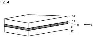
- Figure 4 A further embodiment of the invention is described with reference to Figure 4 . It is noted that for the sake of clearness the schematic drawings in Figure 4 and Figure 2 are not to scale.
- the cladding consists of two parts, a film 11 and an outer cladding 12.
- a suitable cladding material 10, 12 to use with waveguide core 9 formed from LN can be silicon (Si) since over THz range its absorption coefficient is two orders of magnitude smaller than that of the LN. In addition its index of refraction is also smaller in this range.
- Si silicon
- the problem is that over the typical frequency range of pumping the index of refraction of Si forming cladding 10 is greater than the index of refraction of the LN forming waveguide core 9.
- a thin film having an index of refraction smaller over the frequency range of pumping than that of the waveguide core 9 is positioned in the vicinity of the core.
- the thickness of the film is nearly one order of magnitude greater than the pump wavelength and nearly one order of magnitude smaller than the THz wavelength.
- polyethylene can be used as suitable material for film 11.
- cladding 10 is provided with outer cladding 12 preferably made of silicon.
- the embodiments of the invention may be realized in compact form offering a wide range of practical application.
- the materials used in the exemplary embodiments of the invention are not limited to LN, Si and polyethylene, other materials of similar nature may also be used.
Landscapes
- Physics & Mathematics (AREA)
- Nonlinear Science (AREA)
- General Physics & Mathematics (AREA)
- Optics & Photonics (AREA)
- Optical Modulation, Optical Deflection, Nonlinear Optics, Optical Demodulation, Optical Logic Elements (AREA)
Description
- The invention relates to a waveguide structured terahertz (THz) radiation source having a waveguide core of great non-linear optical coefficient and of great absorption. THz radiation is generated through optical rectification of ultrashort light pulses in the visible or near infrared range. The radiation source is adapted to behave as a waveguide in pumping and also in THz range. The THz waveguide source has a cladding of orders of magnitude smaller absorption coefficient in the THz range than that of the core. Due to this the influence of absorption is diminished while the efficiency of generating THz radiation is enhanced.
- In recent years application of THz radiation sources in the field of medical diagnostics and various security techniques (e.g. passenger check at airports, drug analysis) has developed dynamically.
- Generation of THz frequency with non-linear optical techniques is a known and effective method. In the known solutions in order to achieve good efficiency it is a requirement for the non-linear optical material to have great non-linear coefficient and small absorption coefficient. To ensure velocity matching between pumping and the generated signal is also a requirement.
- A scheme for generating THz radiation based on optical rectification is described in the publication titled "Velocity matching by pulse front tilting for large area THz- pulse generation" by J. Hebling, G. Almasi, I.Z. Kozma and J. Kuhl (Opt Expr. 10, 1161 2002). Here LiNbO3 (hereinafter LN) crystal is used as non-linear optical medium because of its outstanding great non-linear optical coefficient. In case of optical rectification matching the group velocity of the pump pulse and the phase velocity of the generated THz radiation is required, that is the condition of velocity matching must be fulfilled. Velocity matching in case of LN is a big problem since the group velocity of pumping is greater than the phase velocity of the THz radiation. To overcome this problem the above document proposes the tilted pulse front excitation scheme. However, the above mentioned publication does not take measures to eliminate the effect of the significant absorption in the LN on the <10 THz frequency range (see "Temperature dependence of the absorption and refraction of Mg-doped congruent and stoichiometric LiNbO3 in the THz range" by L. Pálfalvi, J. Hebling, J. Kuhl, A. Peter and K. Polgár (J. Appl. Phys. 97, 123505, 2005)).
- Radiation sources are known which in order to fulfil the condition of velocity matching use a waveguide structure which behaves as waveguide for pumping as well as for the THz signal. These are described in the following publications: "Design of terahertz waveguides for efficient parametric terahertz generation by W. Shi, Y. Ding (Appl. Phys. Lett 82, 4435 2003) and
US patent No. 7272158 B1 titled "Highly efficient waveguide pulsed THz electromagnetic radiation source and group-matched waveguide THz electromagnetic radiation source" by R.R. Hayes, S. lonov, I. V. lonova. This solution ensures that the field strength of the THz components generated in different points are added up in the same phase which is an important factor for increased efficiency of radiation generation. However, the waveguide structure by itself does not solve the problem caused by the significant absorption of LN in the THz range. - In other solutions in order to eliminate the deteriorative effect of absorption the thin LN layer (having a thickness in the range of micrometers) is sandwiched between a material having an absorption coefficient essentially smaller than that of the LN (see the documents titled: "Highly efficient optical-to-terahertz conversion in a sandwich structure with LiNbO3 core" by S. B. Bodrov, A. N. Stepanov, M. I. Bakunov, B. V. Shishkin, I. E. Ilyakov, R.A. Akhmedzhanov, Opt. Expr. 17, 1871 2009 and "Extremely frequency-widened terahertz wave generation using Cherenkov-type radiation" by K. Suizu, K. Koketsu, T. Shibuya, T. Tsutsui, T. Akiba, K. Kawase, Opt. Expr. 17, 6676 2009). The parameters of the material and geometry are selected so that the structure does not behave as a waveguide in the THz range - as it is shown in the first Figures of the above mentioned publications - since the THz radiation at the point of radiation leaves LN in a slanting direction when entering the neighbouring medium. In this manner the length of propagation in LN is significantly decreased thereby the loss in absorption is minimized. However, in case of this type of excitation - since the interaction length is significantly smaller - the efficiency of THz generation is lower than in the case of velocity matched waveguide. In addition, in this case the intensity of the THz components generated at individual points is summed up instead of the same phase field strengths as it is the case with velocity matched waveguide.
- In patent application
US 20080159342 A1 a complicated dual waveguide structure is used for minimizing the absorption of an optic material with great non-linearity. The solution described inUS 20080159342 A1 is complicated and has several functional disadvantages. - In patent application
US 20080159342 A1 the dual waveguide structure channel (the range where the effective THz excitation takes place) is narrowed down to a cross-section of 90 nm x 9 µm. An object of the present invention is to avoid this geometric limitation of the waveguide structure in order to increase the THz energy. Another object is to ensure the variability of the angle of tilt for the pulse front enabling tuning of the radiation source. - In patent application
US 20080159342 A1 the difference frequency generated by about 1500 nm wavelength pump beams provides a continuous or quasi continuous THz radiation, whereas in the solution according to the present invention wideband, high energy terahertz pulses are generated through optical rectification by using a single pump beam thus providing a simpler means for pumping. - In patent application
US 20080159342 the thickness of the waveguide cladding is limited. A further object of the present invention is to eliminate this disadvantage by enabling the use of a waveguide cladding of optional thickness which makes technical implementation simpler. - In patent application
US 20080159342 the upper limit for the index of refraction of the material of the waveguide cladding is 2.5. A further object of the present invention is to eliminate this unfavourable restriction. It has been realized that in case of tilted pulse front excitation there is no such limit. - According to the foregoing the object of the present invention is to provide a THz radiation source with enhanced efficiency and a high structural uniformity. This object is realized ⌠ by using a great-nonlinear optical coefficient material the THz absorption coefficient of which does not need particular restrictions since its unfavourable effect is diminished significantly. According to the present invention the absorption coefficient of the used material may be one order of magnitude greater as compared to known implementations. This results a greater interaction length and thus a greater THz radiation generating efficiency. ⌠ ⌠
⌠ : , in accordance withClaim 1,
⌠ ⌠ : Possible further preferred embodiments of the THz radiation source are set forth in Claims 2 to 7. - In the following a detailed description of the invention will be given with reference to the accompanying drawings in which:
-
Figure 1 shows the apparatus for generating THz radiation schematically; -
Figure 2 is a three-dimensional schematic drawing of the THz waveguide source; -
Figure 3 schematically shows the tilted pulse front excitation of THz radiation in THz waveguide source; -
Figure 4 is a three-dimensional schematic drawing of an embodiment of the THz waveguide source including a film. - An embodiment and operation of the radiation source according to the invention is described with reference to
Figures 1, 2 and 3 . -
Figure 1 schematically shows the arrangement of the apparatus for generating THz radiation. The radiation source comprises the following functional components:
Optical grating 6 serving for tilting the intensity front of the laser beam 4 generated by pump laser 2. The pulse front tilt oflaser beam 5 is caused by diffraction on theoptical grating 6 and passing throughimaging lens 7. Then thelaser beam 5 with tilted intensity front reaches (enters)THz waveguide source 3. At the output ofTHz waveguide source 3THz radiation 8 emerges. Functional arrangement of the essential components of the invention is also shown inFigure 1 . THz waveguide source is shown inFigure 2 where theTHz waveguide source 3 includes awaveguide core 9 sandwiched incladding 10. - In the following the operation of the THz waveguide source is described with reference to the Figures. The energy source for THz generation is ensured by pump laser 2 typically operating in the visible or near infrared range producing pulses typically with a femtosecond - picosecond pulse duration for departing laser beam 4. Departing laser beam 4 diffracted by
optical grating 6 becomes pulse front tilted which means that the intensity front gets tilted relative to the wave front, as it is described in details in publication titled "Tunable THz pulse generation by optical rectification of ultrashort laser pulses with tilted pulse front" (J. Hebling, A.G. Stepanov, G. Almási, B. Bartal, J. Kuhl Appl. Phys. B 78 593 2004). By means ofimaging lens 7 tilted pulsefront laser beam 5 is directed to the input ofwaveguide core 9. By properly selecting the grating constant and the geometric arrangement ofoptical grating 6 it can be attained that the intensity front of the tilted pulse front laser beam be inclined incore 9 to such an extent that velocity matching between pump pulses and the generated THz radiation may be realized. InFigure 3 excitation of tilted pulse front THz radiation inTHz waveguide source 3 is shown schematically. Slanted lines in the Figure show the tilt of the pulse front before the waveguide and in the waveguide (see "Tunable THz pulse generation by optical rectification of ultrashort laser pulses with tilted pulse front" by J. Hebling, A.G. Stepanov, G. Almási, B. Bartal, J. Kuhl (Appl. Phys. B 78 593 2004)). Owing to the waveguide based operation - in case of optimal geometry and typical pumping - pulse front tilt of lesser degree is needed than in a crystal (see publication titled "Velocity matching by pulse front tilting for large area THz-pulse generation" by J. Hebling, G. Almási, I.Z. Kozma and J. Kuhl (Opt. Expr. 10, 1161 2002)). By this means the effective interaction length of the pump pulse is increased four times greater thus resulting a greater THz generation efficiency. - There are materials (e.g. LN) which have extremely large non-linear optical coefficient. For this reason they could be promising for generating THz radiation, however, significant absorption (typically 10-100 cm-1) in <10 THz frequency range is rather disadvantageous.
- The essence of the invention is to use efficiently - as THz radiation source - a material having great non-linearity and high absorption.
- To minimize the absorption losses according to the invention the following measures are taken. On the one hand the material of the
cladding 10 is selected so that the absorption coefficient of thecladding 10 is smaller than that of thewaveguide core 9. On the other hand the thickness of thewaveguide core 9 andcladding 10 is determined so that high percentage (80-90%) of the energy of the generated THz radiation propagates in cladding 10 (B. E. A. Saleh, M. C. Teich: "Fundamentals of Photonics, 2nd edition (2007) ISBN-10: 0-471-35832-0). In addition it is required forTHz waveguide source 3 to behave as a waveguide in THz frequency range and also in the frequency range of pumping. To this the index of refraction of the material ofcladding 10 must be smaller in the frequency range of pumping and also in the THz frequency range than that of thewaveguide core 9. - Owing to the mechanism of generating THz radiation the advantage of the solution of the present invention as opposed to the solutions described in the publications mentioned earlier ("Highly efficient optical-to-terahertz conversion in a sandwich structure with LiNbO3 core" by S. B. Bodrov, A. N. Stepanov, M. I. Bakunov, B. V. Shishkin, I. E. Ilyakov, R.A. Akhmedzhanov, Opt. Expr. 17, 1871 2009 and "Extremely frequency-widened terahertz wave generation using Cherenkov-type radiation" by K. Suizu, K. Koketsu, T. Shibuya, T. Tsutsui, T. Akiba, K. Kawase, Opt. Expr. 17, 6676 2009) is that the field strengths of the THz components generated at different points are added together instead of their intensity thus enhancing the efficiency of THz radiation generation since the intensity is proportional to the square of the field strength.
- A further embodiment of the invention is described with reference to
Figure 4 . It is noted that for the sake of clearness the schematic drawings inFigure 4 andFigure 2 are not to scale. InFigure 4 the cladding consists of two parts, afilm 11 and anouter cladding 12. - A
suitable cladding material waveguide core 9 formed from LN (or other material with similar parameters) can be silicon (Si) since over THz range its absorption coefficient is two orders of magnitude smaller than that of the LN. In addition its index of refraction is also smaller in this range. However, the problem is that over the typical frequency range of pumping the index of refraction ofSi forming cladding 10 is greater than the index of refraction of the LN formingwaveguide core 9. - To solve this problem a thin film having an index of refraction smaller over the frequency range of pumping than that of the
waveguide core 9 is positioned in the vicinity of the core. The thickness of the film is nearly one order of magnitude greater than the pump wavelength and nearly one order of magnitude smaller than the THz wavelength. For example in an LN-Si compositeTHz waveguide source 3 polyethylene can be used as suitable material forfilm 11. In thisembodiment cladding 10 is provided withouter cladding 12 preferably made of silicon. - Through the described embodiments of the invention it can be seen that materials with great non-linear coefficient may be used for highly efficient THz generation even if they have a great absorption coefficient. With the solution of the invention it becomes possible to make the cladding from materials having greater index of refraction over the frequency range of pumping than that of the core by applying a film with a small index of refraction between the core and the cladding.
- The embodiments of the invention may be realized in compact form offering a wide range of practical application. The materials used in the exemplary embodiments of the invention are not limited to LN, Si and polyethylene, other materials of similar nature may also be used.
Claims (7)
- A THz radiation source comprising a light source (2) and a pulse excited THz waveguide source (3) for producing THz radiation based on optical rectification having a waveguide core (9) formed from a nonlinear optical material with a first absorption coefficient over the THz range, said waveguide source (3) is provided with a cladding (10) with a second absorption coefficient smaller over the THz range than the first absorption coefficient of the waveguide core (9), wherein said waveguide source (3) is a waveguide for pumping and said waveguide source (3) is also a waveguide for the THz range.
characterized in that- said light source (2) is adapted to produce a pump light (5) with tilted pulse front to excite said waveguide source (3) in said waveguide core (9) for velocity matching between the pump light pulse and the THz radiation. - The THz radiation source according to claim 1, characterized in that the thickness of the waveguide core (9) and the cladding (10) is determined so that 80 to 90% of the energy of the generated THz radiation propagates in the cladding (10).
- The THz radiation source according to claim 1 or 2, characterized in that a film (11) forming a part of said THz waveguide source (3) and having an index of refraction smaller at the pump wavelength than that of the waveguide core (9) is arranged between said waveguide core (9) and said cladding (10).
- The THz radiation source according to claim 1 or 2, characterized in that the material of said waveguide core (9) is LiNbO3.
- The THz radiation source according to claim 1 or 2, characterized in that said waveguide core (9) is provided with the waveguide cladding (10) made of silicon.
- The THz radiation source according to any of claims 3 to 5, characterized in that said film (11) is made of polyethylene.
- The THz radiation source according to any preceding claims, characterized in that the first absorption coefficient is greater than 10 cm-1 over the THz range.
Applications Claiming Priority (2)
| Application Number | Priority Date | Filing Date | Title |
|---|---|---|---|
| HU1000514A HU229943B1 (en) | 2010-09-22 | 2010-09-22 | Optical excited thz radiation source based on rectification |
| PCT/HU2011/000081 WO2012038768A1 (en) | 2010-09-22 | 2011-08-05 | Pulse excited thz waveguide source based on optical rectification |
Publications (2)
| Publication Number | Publication Date |
|---|---|
| EP2619626A1 EP2619626A1 (en) | 2013-07-31 |
| EP2619626B1 true EP2619626B1 (en) | 2019-07-10 |
Family
ID=89989969
Family Applications (1)
| Application Number | Title | Priority Date | Filing Date |
|---|---|---|---|
| EP11748709.0A Active EP2619626B1 (en) | 2010-09-22 | 2011-08-05 | Pulse excited thz waveguide source based on optical rectification |
Country Status (4)
| Country | Link |
|---|---|
| US (1) | US9128349B2 (en) |
| EP (1) | EP2619626B1 (en) |
| HU (2) | HU229943B1 (en) |
| WO (1) | WO2012038768A1 (en) |
Families Citing this family (2)
| Publication number | Priority date | Publication date | Assignee | Title |
|---|---|---|---|---|
| HU229943B1 (en) * | 2010-09-22 | 2015-01-28 | Pecsi Tudomanyegyetem | Optical excited thz radiation source based on rectification |
| HU231075B1 (en) * | 2015-09-30 | 2020-05-28 | Pécsi Tudományegyetem | Method for producing terahertz radiation and terahertz radiation source |
Family Cites Families (10)
| Publication number | Priority date | Publication date | Assignee | Title |
|---|---|---|---|---|
| JP2002072269A (en) * | 2000-08-30 | 2002-03-12 | Inst Of Physical & Chemical Res | Terahertz wave generation method and apparatus |
| US8050531B2 (en) * | 2006-09-27 | 2011-11-01 | Anis Rahman | Dendrimer based terahertz generator |
| US20050242287A1 (en) * | 2004-04-30 | 2005-11-03 | Hosain Hakimi | Optical terahertz generator / receiver |
| US7272158B1 (en) | 2005-02-15 | 2007-09-18 | Hrl Laboratories, Llc | Highly efficient waveguide pulsed THz electromagnetic radiation source and group-matched waveguide THz electromagnetic radiation source |
| US7421171B2 (en) * | 2006-06-23 | 2008-09-02 | Massachusetts Institute Of Technology | Efficient terahertz sources by optical rectification in photonic crystals and metamaterials exploiting tailored transverse dispersion relations |
| US7515801B2 (en) | 2006-12-28 | 2009-04-07 | Wisconsin Alumni Research Foundation | Coherent terahertz radiation source |
| JP5098895B2 (en) * | 2008-08-26 | 2012-12-12 | アイシン精機株式会社 | Terahertz wave generation apparatus and terahertz wave generation method |
| JP5666847B2 (en) * | 2009-08-10 | 2015-02-12 | 日本碍子株式会社 | Electromagnetic oscillation element |
| JP5885414B2 (en) * | 2010-08-05 | 2016-03-15 | キヤノン株式会社 | Optical frequency conversion element |
| HU229943B1 (en) * | 2010-09-22 | 2015-01-28 | Pecsi Tudomanyegyetem | Optical excited thz radiation source based on rectification |
-
2010
- 2010-09-22 HU HU1000514A patent/HU229943B1/en not_active IP Right Cessation
-
2011
- 2011-08-05 US US13/825,534 patent/US9128349B2/en active Active
- 2011-08-05 WO PCT/HU2011/000081 patent/WO2012038768A1/en not_active Ceased
- 2011-08-05 EP EP11748709.0A patent/EP2619626B1/en active Active
- 2011-08-05 HU HUE11748709A patent/HUE045578T2/en unknown
Non-Patent Citations (1)
| Title |
|---|
| None * |
Also Published As
| Publication number | Publication date |
|---|---|
| HUE045578T2 (en) | 2020-01-28 |
| EP2619626A1 (en) | 2013-07-31 |
| HU1000514D0 (en) | 2010-11-29 |
| US9128349B2 (en) | 2015-09-08 |
| WO2012038768A1 (en) | 2012-03-29 |
| HUP1000514A2 (en) | 2012-03-28 |
| HU229943B1 (en) | 2015-01-28 |
| US20130259437A1 (en) | 2013-10-03 |
Similar Documents
| Publication | Publication Date | Title |
|---|---|---|
| Vampa et al. | Observation of backward high-harmonic emission from solids | |
| US6856737B1 (en) | Nonlinear optical device | |
| US7953128B2 (en) | Pump recycling scheme for terahertz generation | |
| Ginsberg et al. | Phonon-enhanced nonlinearities in hexagonal boron nitride | |
| EP1821141B1 (en) | Method and device for generating terahertz wave | |
| Bodrov et al. | Highly efficient Cherenkov-type terahertz generation by 2-μm wavelength ultrashort laser pulses in a prism-coupled LiNbO3 layer | |
| Purlys et al. | Spatial filtering by chirped photonic crystals | |
| JP5354582B2 (en) | Terahertz wave generator | |
| Bakunov et al. | Efficient Cherenkov-type optical-to-terahertz converter with terahertz beam combining | |
| KR102550608B1 (en) | Sub-nanosecond extended spectrum generation laser system | |
| Ciriolo et al. | Microfluidic devices for quasi-phase-matching in high-order harmonic generation | |
| JP6997088B2 (en) | How to generate terahertz radiation and terahertz radiation sources | |
| JP5098895B2 (en) | Terahertz wave generation apparatus and terahertz wave generation method | |
| Duda et al. | 10-µJ few-cycle 12-µm source based on difference-frequency generation driven by a 1-kHz mid-wave infrared OPCPA | |
| JPWO2005096088A1 (en) | Light conversion device | |
| Kirsche et al. | Continuously tunable high photon flux high harmonic source | |
| Korobenko et al. | High-harmonic generation in solids driven by counter-propagating pulses | |
| US9128349B2 (en) | Pulse excited THz waveguide source based on optical rectification | |
| WO2010104489A1 (en) | Pump recycling scheme for terahertz generation | |
| Yang et al. | Efficient generation and frequency modulation of quasi-monochromatic terahertz wave in Lithium Niobate subwavelength waveguide | |
| Sun et al. | Terahertz-wave parametric oscillator with a misalignment-resistant tuning cavity | |
| Sychugin et al. | Terahertz Cherenkov radiation from a tightly focused ultrashort laser pulse in an electro-optic medium | |
| US9057928B2 (en) | Efficient frequency conversion | |
| Konoike et al. | On-chip dynamic time reversal of light in a coupled-cavity system | |
| Rashidi et al. | Design of an agile optical switcher based on a 1D silver plasmonic nanograting filled with a nonlinear Kerr material |
Legal Events
| Date | Code | Title | Description |
|---|---|---|---|
| PUAI | Public reference made under article 153(3) epc to a published international application that has entered the european phase |
Free format text: ORIGINAL CODE: 0009012 |
|
| 17P | Request for examination filed |
Effective date: 20130404 |
|
| AK | Designated contracting states |
Kind code of ref document: A1 Designated state(s): AL AT BE BG CH CY CZ DE DK EE ES FI FR GB GR HR HU IE IS IT LI LT LU LV MC MK MT NL NO PL PT RO RS SE SI SK SM TR |
|
| DAX | Request for extension of the european patent (deleted) | ||
| STAA | Information on the status of an ep patent application or granted ep patent |
Free format text: STATUS: EXAMINATION IS IN PROGRESS |
|
| 17Q | First examination report despatched |
Effective date: 20180517 |
|
| GRAP | Despatch of communication of intention to grant a patent |
Free format text: ORIGINAL CODE: EPIDOSNIGR1 |
|
| STAA | Information on the status of an ep patent application or granted ep patent |
Free format text: STATUS: GRANT OF PATENT IS INTENDED |
|
| INTG | Intention to grant announced |
Effective date: 20190116 |
|
| GRAS | Grant fee paid |
Free format text: ORIGINAL CODE: EPIDOSNIGR3 |
|
| GRAA | (expected) grant |
Free format text: ORIGINAL CODE: 0009210 |
|
| STAA | Information on the status of an ep patent application or granted ep patent |
Free format text: STATUS: THE PATENT HAS BEEN GRANTED |
|
| RAP1 | Party data changed (applicant data changed or rights of an application transferred) |
Owner name: PECSI TUDOMANYEGYETEM |
|
| AK | Designated contracting states |
Kind code of ref document: B1 Designated state(s): AL AT BE BG CH CY CZ DE DK EE ES FI FR GB GR HR HU IE IS IT LI LT LU LV MC MK MT NL NO PL PT RO RS SE SI SK SM TR |
|
| REG | Reference to a national code |
Ref country code: GB Ref legal event code: FG4D |
|
| RIN1 | Information on inventor provided before grant (corrected) |
Inventor name: HEBLING, JANOS Inventor name: ALMASI, GABOR Inventor name: PALFALVI, LASZLO Inventor name: FUELOEP, JOZSEF |
|
| REG | Reference to a national code |
Ref country code: AT Ref legal event code: REF Ref document number: 1154205 Country of ref document: AT Kind code of ref document: T Effective date: 20190715 Ref country code: CH Ref legal event code: EP |
|
| REG | Reference to a national code |
Ref country code: DE Ref legal event code: R096 Ref document number: 602011060350 Country of ref document: DE |
|
| REG | Reference to a national code |
Ref country code: IE Ref legal event code: FG4D |
|
| REG | Reference to a national code |
Ref country code: CH Ref legal event code: NV Representative=s name: VALIPAT S.A. C/O BOVARD SA NEUCHATEL, CH |
|
| REG | Reference to a national code |
Ref country code: SE Ref legal event code: TRGR |
|
| REG | Reference to a national code |
Ref country code: NL Ref legal event code: FP |
|
| REG | Reference to a national code |
Ref country code: LT Ref legal event code: MG4D |
|
| REG | Reference to a national code |
Ref country code: AT Ref legal event code: MK05 Ref document number: 1154205 Country of ref document: AT Kind code of ref document: T Effective date: 20190710 |
|
| REG | Reference to a national code |
Ref country code: HU Ref legal event code: AG4A Ref document number: E045578 Country of ref document: HU |
|
| PG25 | Lapsed in a contracting state [announced via postgrant information from national office to epo] |
Ref country code: PT Free format text: LAPSE BECAUSE OF FAILURE TO SUBMIT A TRANSLATION OF THE DESCRIPTION OR TO PAY THE FEE WITHIN THE PRESCRIBED TIME-LIMIT Effective date: 20191111 Ref country code: HR Free format text: LAPSE BECAUSE OF FAILURE TO SUBMIT A TRANSLATION OF THE DESCRIPTION OR TO PAY THE FEE WITHIN THE PRESCRIBED TIME-LIMIT Effective date: 20190710 Ref country code: LT Free format text: LAPSE BECAUSE OF FAILURE TO SUBMIT A TRANSLATION OF THE DESCRIPTION OR TO PAY THE FEE WITHIN THE PRESCRIBED TIME-LIMIT Effective date: 20190710 Ref country code: FI Free format text: LAPSE BECAUSE OF FAILURE TO SUBMIT A TRANSLATION OF THE DESCRIPTION OR TO PAY THE FEE WITHIN THE PRESCRIBED TIME-LIMIT Effective date: 20190710 Ref country code: AT Free format text: LAPSE BECAUSE OF FAILURE TO SUBMIT A TRANSLATION OF THE DESCRIPTION OR TO PAY THE FEE WITHIN THE PRESCRIBED TIME-LIMIT Effective date: 20190710 Ref country code: BG Free format text: LAPSE BECAUSE OF FAILURE TO SUBMIT A TRANSLATION OF THE DESCRIPTION OR TO PAY THE FEE WITHIN THE PRESCRIBED TIME-LIMIT Effective date: 20191010 Ref country code: NO Free format text: LAPSE BECAUSE OF FAILURE TO SUBMIT A TRANSLATION OF THE DESCRIPTION OR TO PAY THE FEE WITHIN THE PRESCRIBED TIME-LIMIT Effective date: 20191010 |
|
| PG25 | Lapsed in a contracting state [announced via postgrant information from national office to epo] |
Ref country code: IS Free format text: LAPSE BECAUSE OF FAILURE TO SUBMIT A TRANSLATION OF THE DESCRIPTION OR TO PAY THE FEE WITHIN THE PRESCRIBED TIME-LIMIT Effective date: 20191110 Ref country code: LV Free format text: LAPSE BECAUSE OF FAILURE TO SUBMIT A TRANSLATION OF THE DESCRIPTION OR TO PAY THE FEE WITHIN THE PRESCRIBED TIME-LIMIT Effective date: 20190710 Ref country code: AL Free format text: LAPSE BECAUSE OF FAILURE TO SUBMIT A TRANSLATION OF THE DESCRIPTION OR TO PAY THE FEE WITHIN THE PRESCRIBED TIME-LIMIT Effective date: 20190710 Ref country code: RS Free format text: LAPSE BECAUSE OF FAILURE TO SUBMIT A TRANSLATION OF THE DESCRIPTION OR TO PAY THE FEE WITHIN THE PRESCRIBED TIME-LIMIT Effective date: 20190710 Ref country code: GR Free format text: LAPSE BECAUSE OF FAILURE TO SUBMIT A TRANSLATION OF THE DESCRIPTION OR TO PAY THE FEE WITHIN THE PRESCRIBED TIME-LIMIT Effective date: 20191011 Ref country code: ES Free format text: LAPSE BECAUSE OF FAILURE TO SUBMIT A TRANSLATION OF THE DESCRIPTION OR TO PAY THE FEE WITHIN THE PRESCRIBED TIME-LIMIT Effective date: 20190710 |
|
| PG25 | Lapsed in a contracting state [announced via postgrant information from national office to epo] |
Ref country code: TR Free format text: LAPSE BECAUSE OF FAILURE TO SUBMIT A TRANSLATION OF THE DESCRIPTION OR TO PAY THE FEE WITHIN THE PRESCRIBED TIME-LIMIT Effective date: 20190710 |
|
| PG25 | Lapsed in a contracting state [announced via postgrant information from national office to epo] |
Ref country code: EE Free format text: LAPSE BECAUSE OF FAILURE TO SUBMIT A TRANSLATION OF THE DESCRIPTION OR TO PAY THE FEE WITHIN THE PRESCRIBED TIME-LIMIT Effective date: 20190710 Ref country code: DK Free format text: LAPSE BECAUSE OF FAILURE TO SUBMIT A TRANSLATION OF THE DESCRIPTION OR TO PAY THE FEE WITHIN THE PRESCRIBED TIME-LIMIT Effective date: 20190710 Ref country code: IT Free format text: LAPSE BECAUSE OF FAILURE TO SUBMIT A TRANSLATION OF THE DESCRIPTION OR TO PAY THE FEE WITHIN THE PRESCRIBED TIME-LIMIT Effective date: 20190710 Ref country code: RO Free format text: LAPSE BECAUSE OF FAILURE TO SUBMIT A TRANSLATION OF THE DESCRIPTION OR TO PAY THE FEE WITHIN THE PRESCRIBED TIME-LIMIT Effective date: 20190710 Ref country code: PL Free format text: LAPSE BECAUSE OF FAILURE TO SUBMIT A TRANSLATION OF THE DESCRIPTION OR TO PAY THE FEE WITHIN THE PRESCRIBED TIME-LIMIT Effective date: 20190710 |
|
| PG25 | Lapsed in a contracting state [announced via postgrant information from national office to epo] |
Ref country code: SK Free format text: LAPSE BECAUSE OF FAILURE TO SUBMIT A TRANSLATION OF THE DESCRIPTION OR TO PAY THE FEE WITHIN THE PRESCRIBED TIME-LIMIT Effective date: 20190710 Ref country code: MC Free format text: LAPSE BECAUSE OF FAILURE TO SUBMIT A TRANSLATION OF THE DESCRIPTION OR TO PAY THE FEE WITHIN THE PRESCRIBED TIME-LIMIT Effective date: 20190710 Ref country code: IS Free format text: LAPSE BECAUSE OF FAILURE TO SUBMIT A TRANSLATION OF THE DESCRIPTION OR TO PAY THE FEE WITHIN THE PRESCRIBED TIME-LIMIT Effective date: 20200224 Ref country code: CZ Free format text: LAPSE BECAUSE OF FAILURE TO SUBMIT A TRANSLATION OF THE DESCRIPTION OR TO PAY THE FEE WITHIN THE PRESCRIBED TIME-LIMIT Effective date: 20190710 Ref country code: SM Free format text: LAPSE BECAUSE OF FAILURE TO SUBMIT A TRANSLATION OF THE DESCRIPTION OR TO PAY THE FEE WITHIN THE PRESCRIBED TIME-LIMIT Effective date: 20190710 Ref country code: LU Free format text: LAPSE BECAUSE OF NON-PAYMENT OF DUE FEES Effective date: 20190805 |
|
| REG | Reference to a national code |
Ref country code: BE Ref legal event code: MM Effective date: 20190831 |
|
| REG | Reference to a national code |
Ref country code: DE Ref legal event code: R097 Ref document number: 602011060350 Country of ref document: DE |
|
| PLBE | No opposition filed within time limit |
Free format text: ORIGINAL CODE: 0009261 |
|
| STAA | Information on the status of an ep patent application or granted ep patent |
Free format text: STATUS: NO OPPOSITION FILED WITHIN TIME LIMIT |
|
| PG2D | Information on lapse in contracting state deleted |
Ref country code: IS |
|
| PG25 | Lapsed in a contracting state [announced via postgrant information from national office to epo] |
Ref country code: IE Free format text: LAPSE BECAUSE OF NON-PAYMENT OF DUE FEES Effective date: 20190805 |
|
| 26N | No opposition filed |
Effective date: 20200603 |
|
| PG25 | Lapsed in a contracting state [announced via postgrant information from national office to epo] |
Ref country code: SI Free format text: LAPSE BECAUSE OF FAILURE TO SUBMIT A TRANSLATION OF THE DESCRIPTION OR TO PAY THE FEE WITHIN THE PRESCRIBED TIME-LIMIT Effective date: 20190710 Ref country code: BE Free format text: LAPSE BECAUSE OF NON-PAYMENT OF DUE FEES Effective date: 20190831 |
|
| PG25 | Lapsed in a contracting state [announced via postgrant information from national office to epo] |
Ref country code: CY Free format text: LAPSE BECAUSE OF FAILURE TO SUBMIT A TRANSLATION OF THE DESCRIPTION OR TO PAY THE FEE WITHIN THE PRESCRIBED TIME-LIMIT Effective date: 20190710 |
|
| PG25 | Lapsed in a contracting state [announced via postgrant information from national office to epo] |
Ref country code: MT Free format text: LAPSE BECAUSE OF FAILURE TO SUBMIT A TRANSLATION OF THE DESCRIPTION OR TO PAY THE FEE WITHIN THE PRESCRIBED TIME-LIMIT Effective date: 20190710 |
|
| PG25 | Lapsed in a contracting state [announced via postgrant information from national office to epo] |
Ref country code: MK Free format text: LAPSE BECAUSE OF FAILURE TO SUBMIT A TRANSLATION OF THE DESCRIPTION OR TO PAY THE FEE WITHIN THE PRESCRIBED TIME-LIMIT Effective date: 20190710 |
|
| PGFP | Annual fee paid to national office [announced via postgrant information from national office to epo] |
Ref country code: NL Payment date: 20240821 Year of fee payment: 14 |
|
| PGFP | Annual fee paid to national office [announced via postgrant information from national office to epo] |
Ref country code: DE Payment date: 20240821 Year of fee payment: 14 |
|
| PGFP | Annual fee paid to national office [announced via postgrant information from national office to epo] |
Ref country code: GB Payment date: 20240826 Year of fee payment: 14 |
|
| PGFP | Annual fee paid to national office [announced via postgrant information from national office to epo] |
Ref country code: FR Payment date: 20240829 Year of fee payment: 14 |
|
| PGFP | Annual fee paid to national office [announced via postgrant information from national office to epo] |
Ref country code: CH Payment date: 20240901 Year of fee payment: 14 |
|
| PGFP | Annual fee paid to national office [announced via postgrant information from national office to epo] |
Ref country code: SE Payment date: 20240821 Year of fee payment: 14 |
|
| PGFP | Annual fee paid to national office [announced via postgrant information from national office to epo] |
Ref country code: HU Payment date: 20251007 Year of fee payment: 15 |
|
| REG | Reference to a national code |
Ref country code: DE Ref legal event code: R119 Ref document number: 602011060350 Country of ref document: DE |
|
| REG | Reference to a national code |
Ref country code: CH Ref legal event code: H13 Free format text: ST27 STATUS EVENT CODE: U-0-0-H10-H13 (AS PROVIDED BY THE NATIONAL OFFICE) Effective date: 20260324 |
|
| REG | Reference to a national code |
Ref country code: NL Ref legal event code: MM Effective date: 20250901 |
|
| PG25 | Lapsed in a contracting state [announced via postgrant information from national office to epo] |
Ref country code: CH Free format text: LAPSE BECAUSE OF NON-PAYMENT OF DUE FEES Effective date: 20250831 |
|
| GBPC | Gb: european patent ceased through non-payment of renewal fee |
Effective date: 20250805 |