EP2619555B1 - Automated wood species identification - Google Patents
Automated wood species identification Download PDFInfo
- Publication number
- EP2619555B1 EP2619555B1 EP11827642.7A EP11827642A EP2619555B1 EP 2619555 B1 EP2619555 B1 EP 2619555B1 EP 11827642 A EP11827642 A EP 11827642A EP 2619555 B1 EP2619555 B1 EP 2619555B1
- Authority
- EP
- European Patent Office
- Prior art keywords
- pitch
- workpiece
- wood species
- wood
- imaging module
- Prior art date
- Legal status (The legal status is an assumption and is not a legal conclusion. Google has not performed a legal analysis and makes no representation as to the accuracy of the status listed.)
- Not-in-force
Links
- 239000002023 wood Substances 0.000 title claims description 92
- 238000003384 imaging method Methods 0.000 claims description 75
- 230000005855 radiation Effects 0.000 claims description 58
- 238000000034 method Methods 0.000 claims description 17
- 230000008021 deposition Effects 0.000 claims description 10
- 230000004044 response Effects 0.000 claims description 6
- 238000005520 cutting process Methods 0.000 claims description 5
- 230000005670 electromagnetic radiation Effects 0.000 claims description 5
- 238000001514 detection method Methods 0.000 claims description 3
- 238000003860 storage Methods 0.000 claims description 3
- 238000010521 absorption reaction Methods 0.000 claims 2
- 241000894007 species Species 0.000 description 61
- 241000018646 Pinus brutia Species 0.000 description 9
- 230000003287 optical effect Effects 0.000 description 7
- 241000218657 Picea Species 0.000 description 6
- 235000008331 Pinus X rigitaeda Nutrition 0.000 description 5
- 235000011613 Pinus brutia Nutrition 0.000 description 5
- 235000014466 Douglas bleu Nutrition 0.000 description 3
- 240000001416 Pseudotsuga menziesii Species 0.000 description 3
- 235000005386 Pseudotsuga menziesii var menziesii Nutrition 0.000 description 3
- 230000007547 defect Effects 0.000 description 3
- 230000008569 process Effects 0.000 description 3
- 235000007173 Abies balsamea Nutrition 0.000 description 2
- 244000283070 Abies balsamea Species 0.000 description 2
- 241000218652 Larix Species 0.000 description 2
- 235000005590 Larix decidua Nutrition 0.000 description 2
- 244000019397 Pinus jeffreyi Species 0.000 description 2
- 235000013267 Pinus ponderosa Nutrition 0.000 description 2
- 240000007320 Pinus strobus Species 0.000 description 2
- 241000219000 Populus Species 0.000 description 2
- 238000003491 array Methods 0.000 description 2
- -1 blue stain Substances 0.000 description 2
- 230000006835 compression Effects 0.000 description 2
- 238000007906 compression Methods 0.000 description 2
- 238000010586 diagram Methods 0.000 description 2
- 239000000835 fiber Substances 0.000 description 2
- 230000007246 mechanism Effects 0.000 description 2
- 239000011347 resin Substances 0.000 description 2
- 229920005989 resin Polymers 0.000 description 2
- 239000004065 semiconductor Substances 0.000 description 2
- 238000001228 spectrum Methods 0.000 description 2
- 241000208140 Acer Species 0.000 description 1
- 101000878595 Arabidopsis thaliana Squalene synthase 1 Proteins 0.000 description 1
- 239000004857 Balsam Substances 0.000 description 1
- 235000018185 Betula X alpestris Nutrition 0.000 description 1
- 235000018212 Betula X uliginosa Nutrition 0.000 description 1
- 241000219495 Betulaceae Species 0.000 description 1
- 241000167854 Bourreria succulenta Species 0.000 description 1
- 101100327917 Caenorhabditis elegans chup-1 gene Proteins 0.000 description 1
- 241000723418 Carya Species 0.000 description 1
- 241000218645 Cedrus Species 0.000 description 1
- 244000301850 Cupressus sempervirens Species 0.000 description 1
- 235000018783 Dacrycarpus dacrydioides Nutrition 0.000 description 1
- 101100536354 Drosophila melanogaster tant gene Proteins 0.000 description 1
- 240000007049 Juglans regia Species 0.000 description 1
- 235000009496 Juglans regia Nutrition 0.000 description 1
- 239000004677 Nylon Substances 0.000 description 1
- 241001236219 Pinus echinata Species 0.000 description 1
- 235000005018 Pinus echinata Nutrition 0.000 description 1
- 235000013269 Pinus ponderosa var ponderosa Nutrition 0.000 description 1
- 235000013268 Pinus ponderosa var scopulorum Nutrition 0.000 description 1
- 235000006237 Pinus sabiniana Nutrition 0.000 description 1
- 235000008578 Pinus strobus Nutrition 0.000 description 1
- 241000183024 Populus tremula Species 0.000 description 1
- 241000219492 Quercus Species 0.000 description 1
- 244000186561 Swietenia macrophylla Species 0.000 description 1
- 230000006978 adaptation Effects 0.000 description 1
- 230000000712 assembly Effects 0.000 description 1
- 238000000429 assembly Methods 0.000 description 1
- 230000008901 benefit Effects 0.000 description 1
- 235000019693 cherries Nutrition 0.000 description 1
- 239000004927 clay Substances 0.000 description 1
- 230000000295 complement effect Effects 0.000 description 1
- 239000002131 composite material Substances 0.000 description 1
- 230000008878 coupling Effects 0.000 description 1
- 238000010168 coupling process Methods 0.000 description 1
- 238000005859 coupling reaction Methods 0.000 description 1
- 230000007423 decrease Effects 0.000 description 1
- 230000003247 decreasing effect Effects 0.000 description 1
- 230000001419 dependent effect Effects 0.000 description 1
- 239000002274 desiccant Substances 0.000 description 1
- 230000005284 excitation Effects 0.000 description 1
- 239000011094 fiberboard Substances 0.000 description 1
- 239000006260 foam Substances 0.000 description 1
- 239000011521 glass Substances 0.000 description 1
- 239000012212 insulator Substances 0.000 description 1
- 238000004519 manufacturing process Methods 0.000 description 1
- 239000000463 material Substances 0.000 description 1
- 229910044991 metal oxide Inorganic materials 0.000 description 1
- 150000004706 metal oxides Chemical class 0.000 description 1
- 235000014571 nuts Nutrition 0.000 description 1
- 229920001778 nylon Polymers 0.000 description 1
- 239000011120 plywood Substances 0.000 description 1
- 238000005096 rolling process Methods 0.000 description 1
- 238000009416 shuttering Methods 0.000 description 1
- 239000000758 substrate Substances 0.000 description 1
- 230000001360 synchronised effect Effects 0.000 description 1
- 238000002604 ultrasonography Methods 0.000 description 1
- 238000001429 visible spectrum Methods 0.000 description 1
- 238000011179 visual inspection Methods 0.000 description 1
- 235000020234 walnut Nutrition 0.000 description 1
Images






Classifications
-
- G—PHYSICS
- G01—MEASURING; TESTING
- G01N—INVESTIGATING OR ANALYSING MATERIALS BY DETERMINING THEIR CHEMICAL OR PHYSICAL PROPERTIES
- G01N21/00—Investigating or analysing materials by the use of optical means, i.e. using sub-millimetre waves, infrared, visible or ultraviolet light
- G01N21/84—Systems specially adapted for particular applications
- G01N21/88—Investigating the presence of flaws or contamination
- G01N21/89—Investigating the presence of flaws or contamination in moving material, e.g. running paper or textiles
- G01N21/892—Investigating the presence of flaws or contamination in moving material, e.g. running paper or textiles characterised by the flaw, defect or object feature examined
- G01N21/898—Irregularities in textured or patterned surfaces, e.g. textiles, wood
- G01N21/8986—Wood
-
- G—PHYSICS
- G01—MEASURING; TESTING
- G01N—INVESTIGATING OR ANALYSING MATERIALS BY DETERMINING THEIR CHEMICAL OR PHYSICAL PROPERTIES
- G01N21/00—Investigating or analysing materials by the use of optical means, i.e. using sub-millimetre waves, infrared, visible or ultraviolet light
- G01N21/84—Systems specially adapted for particular applications
- G01N21/88—Investigating the presence of flaws or contamination
- G01N21/89—Investigating the presence of flaws or contamination in moving material, e.g. running paper or textiles
- G01N21/892—Investigating the presence of flaws or contamination in moving material, e.g. running paper or textiles characterised by the flaw, defect or object feature examined
- G01N21/898—Irregularities in textured or patterned surfaces, e.g. textiles, wood
-
- G—PHYSICS
- G01—MEASURING; TESTING
- G01N—INVESTIGATING OR ANALYSING MATERIALS BY DETERMINING THEIR CHEMICAL OR PHYSICAL PROPERTIES
- G01N33/00—Investigating or analysing materials by specific methods not covered by groups G01N1/00 - G01N31/00
- G01N33/46—Wood
-
- H—ELECTRICITY
- H04—ELECTRIC COMMUNICATION TECHNIQUE
- H04N—PICTORIAL COMMUNICATION, e.g. TELEVISION
- H04N7/00—Television systems
- H04N7/18—Closed-circuit television [CCTV] systems, i.e. systems in which the video signal is not broadcast
- H04N7/183—Closed-circuit television [CCTV] systems, i.e. systems in which the video signal is not broadcast for receiving images from a single remote source
Definitions
- Embodiments herein relate to the field of wood species identification, and, more specifically, to automated methods, systems, and apparatuses for identifying and/or differentiating among wood species.
- Modern lumber manufacturing facilities often will process wood from a variety of tree species. Stems of wood, logs, cants, flitches, boards, and other workpieces may be sorted based on the species or type of tree from which the workpiece is derived. The determination of wood species typically requires visual inspection of the workpiece and determination of the wood species by a human operator.
- JP H07 146236 discloses a method of detecting resin on the surface of a timber.
- US 2008/074653 discloses methods of detecting compression wood, blue stain, or pitch in lumber.
- a light beam is projected towards the wood sample.
- Line or area cameras acquire images of light that is reflected from the wood sample. Based on the intensity of the reflected light at one or more locations on the wood sample, compression wood, blue stain, or pitch may be detected.
- CA 2335784 discloses a wood differentiating system comprising a line-forming laser, a camera and a controller.
- the line-forming laser projects a line of laser light onto a wood lumber and the camera takes a picture of the illuminated area of the wood lumber.
- the controller is capable of differentiating between lumber made of fir and lumber made of spruce, for example.
- Coupled may mean that two or more elements are in direct physical or electrical contact. However, “coupled” may also mean that two or more elements are not in direct contact with each other, but yet still cooperate or interact with each other.
- a phrase in the form "A/B” or in the form “A and/or B” means (A), (B), or (A and B).
- a phrase in the form "at least one of A, B, and C” means (A), (B), (C), (A and B), (A and C), (B and C), or (A, B and C).
- a phrase in the form "(A)B” means (B) or (AB) that is, A is an optional element.
- a computing device may include one or more components of the disclosed apparatuses and/or systems and may be employed to perform one or more methods as disclosed herein.
- a workpiece may be exposed to a beam of radiation from a radiation source.
- the beam of radiation may cause pitch on or within the workpiece to fluoresce.
- the fluorescence characteristics of the workpiece may be detected and/or measured and used to determine pitch content, pitch location. a pitch deposition pattern, pitch emission wavelength, and/or other characteristics of the workpiece. One or more of these characteristics may be used to identify a wood species or group of species from which the workpiece was cut or manufactured.
- one or more pitch characteristics may be used to distinguish workpieces of one wood species (e.g., "pine") from workpieces of one or more other wood species (e.g., spruce and fir) that may be similar in appearance.
- pitch characteristics may be used to identify wood species such as pine, spruce, larch, maple, fir, cypress, hemlock, balsam, birch, hickory, walnut, alder, oak, cherry, cedar, mahogany, cottonwood, aspen, poplar, and/or elm.
- workpiece refers to a unit of wood or wood-based product.
- workpieces include but are not limited to boards, flitches, cants, stems, veneers, and engineered/composite materials derived from wood (e.g., particleboard, waferboard, plywood, fiberboard, and other engineered wood materials known in the art).
- wood species refers to a type or category of tree from which a workpiece was cut, manufactured, or at least partially derived.
- a wood species may include one, two, three or more tree species within a single taxonomic group such as a family, subfamily, or genus.
- a wood species may include one, two, three or more sub-species or varieties within a single taxonomic species.
- three wood species may be "pine,” “spruce,” and “fir,” any or all of which may include multiple tree species or varieties, and the wood species "pine”, for example, may include some or all of the pine species found in North America, including, but not limited to Yellow Pine, Ponderosa Pine, Jeffery Pine, Shortleaf Pine, Bull Pine, Jack Pine, and/or White Pine.
- a wood species may encompass one or more tree species, subspecies, or varieties grouped according to one or more common characteristics, such as pitch content, pitch location, pitch deposition pattern, wood color/tone, density, strength/stiffness, relative monetary value, hardness/softness, etc.
- a single wood species encompassing tree species with a pitch content within a predetermined range or exceeding a predetermined threshold may include species of pine, spruce, and/or fir.
- a single wood species encompassing tree species with similar wood density and/or strength may include Douglas fir and larch.
- a single wood species may encompass one or more tree species having similar pitch deposition patterns.
- pitch refers collectively to any one or all of pitch, resin, resinous deposits, and/or sap.
- FIG. 1 shows a block diagram of a species identification system 100 in accordance with various embodiments.
- species identification system 100 includes an imaging module 112, a radiation source 116, and a processing module 122. Also shown are a workpiece 120 positioned on a transport surface 124, which is operatively coupled to a transport driver 126.
- Processing module 122 may be operatively coupled to any or all of imaging module 112, radiation source 116, transport surface 124, and/or controller 126.
- transport surface 124 may be driven by controller 126 to bring workpiece 120 into the line of sight 114 of imaging module 112.
- Radiation source 116 emits a radiation beam 118 (UV light according to the invention) toward workpiece 120.
- Pitch on/within workpiece 118 absorbs energy from radiation beam 118, causing excitation of atoms in the pitch.
- the pitch reemits energy as visible light (i.e., fluorescence).
- Imaging module 112 captures one or more images of workpiece 120 as the pitch is fluorescing. Imaging module 112 sends the image data to processing module 122. Processing module 122 assembles the received image data into an image of the workpiece or some portion thereof. The assembled image is then analyzed to determine one or more pitch characteristics such as pitch content, pitch location, a pattern of pitch deposition, and/or pitch fluorescence wavelength(s).
- Processing module 122 may use the determined pitch characteristic(s) to identify the wood species of the workpiece.
- identifying the wood species may include identifying a particular genus, species, sub-species, or variety of tree from which the workpiece was cut/derived.
- the determined characteristic(s) may be used to identify a larger group of tree species from which the workpiece was cut/derived.
- the determined characteristic(s) may be used to eliminate one or more species of tree as possible species from which the workpiece may have been cut (e.g., to determine that the workpiece was or was not cut/derived from a pine tree).
- Imaging module 112 may be any device configured to capture an image of a workpiece by converting an optical image to an electric signal.
- imaging module 112 may include a sensor having one or more pixelated metal oxide semiconductors. Suitable sensors include, but are not limited to, a charge-coupled device (CCD) image sensor, an electron multiplying CCD (EMCCD) imager, an active-pixel sensor (APS) imager (e.g., a complementary metal-oxide-semiconductor (CMOS) APS imager), and/or a hybrid CCD/CMOS imager (e.g., a sCMOS imager with CMOS readout integrated circuits coupled to a CCD imaging substrate).
- CCD charge-coupled device
- EMCD electron multiplying CCD
- APS active-pixel sensor
- CMOS complementary metal-oxide-semiconductor
- hybrid CCD/CMOS imager e.g., a sCMOS imager with CMOS readout integrated circuits coupled to
- Imaging module 112 and/or one or more sensors therein may also include one or more shuttering mechanisms, such as a mechanical shutter or shutter transistors.
- a sensor may be a line-scan CMOS imager with shutter transistors positioned adjacent to the active area of each pixel.
- a sensor may be an area-scan CMOS imager with a rolling shutter that exposes different lines of the array at different times.
- a sensor may be an area-scan CMOS imager with uniform synchronous shutter that exposes each pixel of the array simultaneously.
- Imaging module 112 may further include additional components known in the art for use with imaging sensors, such as a circuit board (e.g., a printed circuit board), a lens, a power source, a processor, a memory/storage, a data transfer module (e.g., a wireless transmitter/transceiver, wired connector, etc.), an outer case, and/or one or more mounting elements configured to retain imaging module 112 on or against a support.
- a circuit board e.g., a printed circuit board
- a lens e.g., a lens
- a power source e.g., a power source
- a processor e.g., a processor
- memory/storage e.g., a data transfer module
- an outer case e.g., a wireless transmitter/transceiver, wired connector, etc.
- mounting elements e.g., a wireless transmitter/transceiver, wired connector, etc.
- Imaging module 112 may include one or more filters, such as an optical anti-aliasing filter, Bayer filter/filter mosaic, or other optical filter known in the art.
- at least one filter may be configured to admit visible light and to exclude UV light.
- at least one filter may be configured to exclude UV light and some portion of the visible light spectrum (e.g. wavelengths of 380-475nm, 590-750nm, violet light, blue light, red/orange light, etc.).
- a filter may be configured to admit only light within a particular range of wavelengths, such as 450-620nm, 476-590nm, or 490-580nm). Therefore, imaging module 112 may create image data based on the full visible spectrum of light or only a portion thereof.
- Imaging module 112 may capture successive images of the workpiece in sections as the workpiece is transported on transport surface 124. For example, imaging module 112 may capture successive line images extending across the workpiece transverse to the direction of flow. Imaging module 112 may send the image data to processor 122 as the image data is created (e.g., line by line). Alternatively, imaging module 112 may compile or buffer the image data until the workpiece has passed the imaging module's field of view, sending the collection of image data to processor 122 after the entire workpiece has been imaged. In some embodiments, processor 122 and imaging module 112 are included within an integrated device, while in other embodiments the image data may be transmitted wirelessly or through a wired connection.
- Radiation source 116 may be any source of electromagnetic radiation configured to emit a beam of electromagnetic radiation toward a target.
- radiation source 116 is a UV light source.
- radiation source 116 may include one or more sources of visible or non-visible light, including but not limited to light-emitting diodes (LEDs), lamps/bulbs, lasers, or other light sources known in the art.
- LEDs light-emitting diodes
- radiation source 116 may include one, two, three, four or more linear arrays of LEDs that emit ultraviolet (UV) radiation.
- Radiation source 116 may also include a support medium coupling element configured to attach radiation source 116 (or some portion thereof) to imaging module 112 or to a wall, ceiling, or support surface.
- One or more light sources and/or arrays may be coupled to a timing control feature configured to strobe or pulse the emitted light.
- the timing control feature may also be coupled to processing module 122 and/or imaging module 112 to synchronize the pulsing of emitted light with image capture.
- Radiation source 116 may be positioned above transport surface 124. Light sources within radiation source 116 may be arranged to extend across the transport surface, generally transverse to the direction of flow. In some examples, radiation source 116 may be mounted to or positioned within imaging module 112 and/or processing module 122. In various embodiments, radiation source 116 may be positioned to emit beams of radiation downwardly onto transport surface 124 at an angle of 0° (perpendicular to transport surface 124), -5° to 5°, -15° to 15°, -30° to 30°, -45° to 45° or -50° to 50°.
- imaging module 112 may be positioned vertically above transport surface 124 and at an angle of 0° (perpendicular to transport surface 124), -5° to 5°, -15° to 15°, -30° to 30°, or -50° to 50°. Yet in various embodiments, the imaging module may be maintained at an angle with respect to the radiation source, which in some embodiments may be adjustable. In various embodiments, the angle between the imaging module 112 and the radiation source 116 may be between 2° and 50°
- the relative angles of radiation source 116 and imaging module 112 may be adjusted such that the field of view intersects with the beams of radiation emitted by radiation source 116 at any vertical distance above the upper surface of transport surface 124.
- the adjustment may be made manually or automatically (e.g., by an actuator in response to a command received from processing module 122 ) to accommodate varying workpiece dimensions such as thickness.
- transport surface 124 may be manually or automatically adjusted upward and downward to accommodate varying workpiece dimensions.
- Transport speed may also be adjusted manually or automatically in accordance with the relative angles of radiation source 116 and imaging module 112.
- Controller 126 may calculate/adjust transport speed/position in response to a command from processing module 122.
- Processing module 122 may be any type of computing processor known in the art, including but not limited to a central processing unit, a microprocessor, a graphics processing unit, a digital signal processor, and/or a coprocessor. Processing module 122 may include hardware, software, or a combination of hardware and software. In some embodiments, processing module 122 may be a processing unit of a computing apparatus such as a personal computer. In other embodiments, processing module 122 may be integrated within another system element such as radiation source 116, imaging module 112, and/or controller 126.
- Processing module 122 may include imaging software, wood species reference data, and/or a species determination algorithm for the determination of wood species based on an input of received image data.
- the wood species reference data may include reference values that represent a 'signature profile' for one or more wood species.
- the 'signature profile' of a wood species "pine" may include a pitch content exceeding a predetermined threshold, a pitch fluorescence wavelength of 495-505 nm, and a streaked pitch deposition pattern.
- Processing module 122 may also include executable instructions operable, when executed, to assemble the received image data into a full or partial image of a workpiece and to analyze the assembled image to determine one or more characteristics such as pitch content, pitch location, a pattern of pitch deposition, and/or pitch fluorescence wavelength.
- the executable instructions may be further operable, when executed, to retrieve the species determination algorithm and/or wood species reference data from a local or remote storage/database and to identify the wood species of the workpiece by feeding the characteristic(s) into the algorithm and/or comparing the characteristic(s) to the wood species reference data.
- Processing module 122 may input determined pitch content and pitch fluorescence wavelength into the algorithm to determine the wood species. Alternatively, processing module 122 may compare determined pitch characteristics to the wood species reference data to determine the wood species of the workpiece. In some embodiments, processing module 122 may use the algorithm to determine a possible wood species and may use the reference wood species data to confirm or verify the identification (or vice versa).
- Processing module 122 may also be configured to generate sorting data and/or grading data based on the species determination. Processing module 122 may communicate sorting data or commands to another component of a wood processing system, such as a drop-out mechanism, mechanical sorter, workpiece marking device, or other processor to effectuate sorting or grading of the workpiece. Different sorting or grading rules may be applied to workpieces based on wood species determination. For example, a first set of grading rules may be used for workpieces determined to be of the wood species "pine" and a second set of grading rules may be used for workpieces determined to be of another wood species (e.g., fir or spruce). Grading rules may be applied by processing module 122 to generate grading data and/or commands, which may be sent to another component of the wood processing system as described above.
- a first set of grading rules may be used for workpieces determined to be of the wood species "pine" and a second set of grading rules may be used
- Processing module 122 may communicate a wood species determination, image data, an assembled image of a workpiece, one or more determined pitch characteristics, and/or other data to another processor (e.g., a scanner/optimizer) or other wood processing system component for use in one or more of defect detection, strength/stiffness prediction, grading, sorting, workpiece imaging, or any other process.
- another processor e.g., a scanner/optimizer
- wood processing system component for use in one or more of defect detection, strength/stiffness prediction, grading, sorting, workpiece imaging, or any other process.
- Controller 126 and transport surface 124 may include any combination of elements known in the art for use in transporting workpieces.
- transport surface 124 may include a lugged chain, belt, or other conveyor surface.
- Controller 126 may be configured to drive or otherwise control movement of the lugged chain or belt.
- controller 126 may include a motor operatively coupled to transport surface 124 and may be configured to drive movement of transport surface 124 in a direction of work flow (indicated by Arrow A), in a direction opposite to the direction of work flow (Arrow B), vertically downward (Arrow C), vertically upward (Arrow D), and/or laterally.
- controller 126 may be a computing device and/or processor configured to control the operation of, and/or receive data from, any other component of species identification system 100 and/or one or more components of a workpiece feed path system.
- components may include a scanner/optimizer, a variable speed drive, a fixed speed drive, a sorting apparatus, a drop-out apparatus, a workpiece positioner configured to flip, turn, or rotate a workpiece, a camera/imaging module positioner, a cutting device, a light or light array, an imager, a workpiece marking apparatus, and/or a conveyor.
- Imaging modules 112 and/or radiation sources 116 may vary among embodiments.
- Alternative embodiments may include two, three, four, five or more imaging modules 112 and/or radiation sources 116.
- one or more imaging modules 112 and radiation sources 116 may be positioned below transport surface 124 and configured to capture an image of the bottom surface of workpiece 120.
- one or more imaging modules 112 and radiation sources 116 may be positioned along or proximal to one or both sides of transport surface 124 and angled to target the top, bottom, or one or more sides of workpiece 120.
- two or more imaging modules 112 may be arranged to provide occlusionless imaging of workpieces as described in U.S. Patent No. 7,751,612 .
- the imaging modules 112 may have fields of view that overlap and/or are partially obstructed by transport surface 124, a frame, a support, or any other component of a wood processing system.
- the imaging modules 112 may image the bottom, top, and/or sides of the workpiece as described above, sending image data to the processing module 122 .
- Processing module 122 may combine the image data from the imaging modules to obtain a complete and unobstructed image of the workpiece.
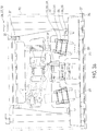
- Figure 2 illustrates an example of a radiation source and imaging module configuration, in accordance with the above-described embodiments.
- the illustrated configuration may be provided as a component of a wood processing system or added to an existing wood processing system (e.g., added to an existing lumber transport in a sawmill facility).
- imaging module 212 and radiation source 216 are shown positioned in proximity to a workpiece 220.
- imaging module 212 includes a CMOS array camera (1536 x 512 pixels, monochrome) with a 8mm F1.4 lens, a 12 VDC to 24 VDC power supply, and a 10.5" (+/- 1.5") sensor standoff.
- the CMOS array camera is contained within a sealed sensor package. Additional details of imaging module 212 are provided in Figures 3a-3d and identified in the accompanying Chart 1, below.
- Chart 1 MK QTY DESCRIPTION 231 1 GASKET-ENCLOSURE 232 8 CAPSCREW 8-32X3/4 SKT HD 233 2 RETAINING CAP LASER 234 2 ALIGNMENT BALL LASER 235 1 MOUNT-CAMERA ARRAY 236 2 NUT JAM 5/8" SS 1/4" THICK 237 2 SENSOR RET.
- some imaging modules may include one or more optical lasers 260/261.
- imaging modules 212 may lack an integrated optical laser.
- Optical lasers may be used, for example, to guide repositioning and/or adjustment of imaging module 212, radiation source 216, or the position/speed of a transport surface.
- optical lasers may be used to induce emission of light from a workpiece.
- some imaging modules 212 may include one or more radiation sources (e.g. UV light sources) and may lack an external radiation source 216.
- Radiation source 216 includes an external linear UV LED light source 285 with a peak wavelength of 365 nm, a 48 VDC power supply, and a heat sink 226. As shown in Figures 4a-4e and the accompanying Chart 2 below, radiation source 216 may include additional components, such as a thermostat 292.
- Mounting assembly 224 may include one or more mechanical fasteners configured to fasten radiation source 216 and/or imaging module 212 to another structure or support such as a wall, ceiling, or frame. Mounting assembly 224 may configured to accommodate manual or automatic repositioning of radiation source 216 and/or imaging module 212.
- imaging module 212 may be pivotally or movably coupled to a first portion of mounting assembly 224
- radiation source 216 may be pivotally or movably coupled to a second portion of mounting assembly 224
- a third portion of mounting assembly 224 may be coupled to the first portion, the second portion, and to a wall, ceiling, or frame.
- Mounting assembly 224 may further include one or more actuators coupled, for example, to a processing module (e.g., processing module 122, Figure 1 ).
- the actuators may be configured to adjust the position and/or angle of the imaging module and/or mounting assembly in response to a command from the processing module. While Figure 2 shows radiation source 216 positioned at an angle of about 14° from vertical and imaging module 212 at an angle of 2° from vertical, the relative positions of these components may vary as discussed above with reference to Figure 1 .
- an imaging module and radiation source may be positioned proximal to a workpiece support, such as a transport.
- the radiation source may be configured to emit one or more beams of light, such as a line of UV light that extends across the workpiece (i.e. transverse to the direction of transport).
- the radiation source and imaging module may be positioned such that the field of view of the imaging module intersects the light emitted by the radiation source. The intersection may occur on or above the upper surface of the transport.
- the workpiece As a workpiece is translocated on the transport in the direction of flow, the workpiece is contacted by the emitted light as described above. Pitch within the illuminated portion of the workpiece may absorb energy from the emitted light and reemit energy as visible light, such as visible light in the green spectrum.
- the imaging module may capture an image of the workpiece, such as a line image corresponding to the illuminated portion. The imaging module may send the captured image to a processing module coupled to the imaging module and/or radiation source.
- the processing module may assemble the received images into a full or partial image of the workpiece.
- the processing module may analyze the assembled image to determine one or more pitch characteristics.
- the processing module may then determine the wood species of the workpiece based at least on the one or more pitch characteristics.
- the determination may also be at least partially based on other received data, such as color/tone data, wood grain data, density data, and/or other received data corresponding to a physical characteristic of the workpiece.
- Such data may be received, for example, from a scanner, a camera, ultrasound, X-ray, or other device.
- the processing module may further use the image data, assembled image, pitch characteristics, wood species data, or other data to another device (e.g., scanner/optimizer, processor, computer, etc.) to determine sorting, grading, defect detection, or other process, or send the data to another device (e.g., a scanner/optimizer, processor, controller, or computer) for any or all of those purposes.
- another device e.g., scanner/optimizer, processor, computer, etc.
- a scanner/optimizer, processor, controller, or computer e.g., a scanner/optimizer, processor, controller, or computer
- the processing module may determine a grading system or sorting decision to be applied to a workpiece based on the determination of wood species.
- the processing module may send the assembled image of the workpiece and/or the species determination to another processor.
- One or both processors may integrate the assembled image with another image of the workpiece and analyze the integrated image to detect defects, determine an optimized cutting solution, predict strength/stiffness, assign a grading system to be used, determine a sorting decision, determine an optimized position for the workpiece, adjust a guide element or cutting element of a cutting or wood processing machine, and/or send a command to another component of a lumber processing system in accordance with any of the above determinations, as described above.
Landscapes
- Life Sciences & Earth Sciences (AREA)
- Engineering & Computer Science (AREA)
- Chemical & Material Sciences (AREA)
- Wood Science & Technology (AREA)
- Health & Medical Sciences (AREA)
- Textile Engineering (AREA)
- General Physics & Mathematics (AREA)
- Analytical Chemistry (AREA)
- Biochemistry (AREA)
- General Health & Medical Sciences (AREA)
- Physics & Mathematics (AREA)
- Immunology (AREA)
- Pathology (AREA)
- Food Science & Technology (AREA)
- Medicinal Chemistry (AREA)
- Multimedia (AREA)
- Signal Processing (AREA)
- Investigating, Analyzing Materials By Fluorescence Or Luminescence (AREA)
- Investigating Materials By The Use Of Optical Means Adapted For Particular Applications (AREA)
- Length Measuring Devices By Optical Means (AREA)
- Chemical And Physical Treatments For Wood And The Like (AREA)
Description
- The present application claims the benefit of
U.S. Provisional Patent Application No. 61/386,332, filed September 24, 2010 - Embodiments herein relate to the field of wood species identification, and, more specifically, to automated methods, systems, and apparatuses for identifying and/or differentiating among wood species.
- Modern lumber manufacturing facilities often will process wood from a variety of tree species. Stems of wood, logs, cants, flitches, boards, and other workpieces may be sorted based on the species or type of tree from which the workpiece is derived. The determination of wood species typically requires visual inspection of the workpiece and determination of the wood species by a human operator.
-
JP H07 146236 -
US 2008/074653 discloses methods of detecting compression wood, blue stain, or pitch in lumber. A light beam is projected towards the wood sample. Line or area cameras acquire images of light that is reflected from the wood sample. Based on the intensity of the reflected light at one or more locations on the wood sample, compression wood, blue stain, or pitch may be detected. -
CA 2335784 discloses a wood differentiating system comprising a line-forming laser, a camera and a controller. The line-forming laser projects a line of laser light onto a wood lumber and the camera takes a picture of the illuminated area of the wood lumber. By evaluating how the fibers of the wood scatter light, the controller is capable of differentiating between lumber made of fir and lumber made of spruce, for example. - "The Identification of Douglas-Fir Wood", US Forest Service Research Note, 1 May 1963, discloses ways to identify Douglas-Fir wood.
- Embodiments will be readily understood by the following detailed description in conjunction with the accompanying drawings. Embodiments are illustrated by way of example and not by way of limitation in the figures of the accompanying drawings.
-
Figure 1 shows a block diagram of aspecies identification system 100 in accordance with various embodiments; -
Figure 2 illustrates an example of a radiation source and imaging module configuration for use to practice various embodiments; -
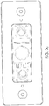
Figures 3a-3d illustrate the imaging module ofFigure 2 in accordance with various embodiments; -
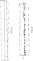
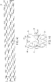
Figures 4a-4e illustrate the radiation source ofFigure 2 in accordance with various embodiments; and -
Figures 5a and5b illustrate an electrical schematic of an imaging module and radiation source in accordance with various embodiments. - According to an aspect of the present invention, there is provided a method according to
claim 1. - According to another aspect of the present invention, there is provided a system according to
claim 7. - In the following detailed description, reference is made to the accompanying drawings which form a part hereof, and in which are shown by way of illustration embodiments that may be practiced. It is to be understood that other embodiments may be utilized and structural or logical changes may be made without departing from the scope. Therefore, the following detailed description is not to be taken in a limiting sense, and the scope of embodiments is defined by the appended claims.
- Various operations may be described as multiple discrete operations in turn, in a manner that may be helpful in understanding embodiments; however, the order of description should not be construed to imply that these operations are order dependent.
- The description may use perspective-based descriptions such as up/down, back/front, and top/bottom. Such descriptions are merely used to facilitate the discussion and are not intended to restrict the application of disclosed embodiments.
- The terms "coupled" and "connected," along with their derivatives, may be used. It should be understood that these terms are not intended as synonyms for each other. Rather, in particular embodiments, "connected" may be used to indicate that two or more elements are in direct physical or electrical contact with each other. "Coupled" may mean that two or more elements are in direct physical or electrical contact. However, "coupled" may also mean that two or more elements are not in direct contact with each other, but yet still cooperate or interact with each other.
- For the purposes of the description, a phrase in the form "A/B" or in the form "A and/or B" means (A), (B), or (A and B). For the purposes of the description, a phrase in the form "at least one of A, B, and C" means (A), (B), (C), (A and B), (A and C), (B and C), or (A, B and C). For the purposes of the description, a phrase in the form "(A)B" means (B) or (AB) that is, A is an optional element.
- The description may use the terms "embodiment" or "embodiments," which may each refer to one or more of the same or different embodiments. Furthermore, the terms "comprising," "including," "having," and the like, as used with respect to embodiments, are synonymous.
- In various embodiments, methods, apparatuses, and systems are provided for automated identification of wood species based on one or more pitch characteristics. In exemplary embodiments, a computing device may include one or more components of the disclosed apparatuses and/or systems and may be employed to perform one or more methods as disclosed herein.
- As provided herein, a workpiece may be exposed to a beam of radiation from a radiation source. The beam of radiation may cause pitch on or within the workpiece to fluoresce. The fluorescence characteristics of the workpiece may be detected and/or measured and used to determine pitch content, pitch location. a pitch deposition pattern, pitch emission wavelength, and/or other characteristics of the workpiece. One or more of these characteristics may be used to identify a wood species or group of species from which the workpiece was cut or manufactured.
- In some examples, one or more pitch characteristics may be used to distinguish workpieces of one wood species (e.g., "pine") from workpieces of one or more other wood species (e.g., spruce and fir) that may be similar in appearance. In other examples, pitch characteristics may be used to identify wood species such as pine, spruce, larch, maple, fir, cypress, hemlock, balsam, birch, hickory, walnut, alder, oak, cherry, cedar, mahogany, cottonwood, aspen, poplar, and/or elm.
- As used herein, the term "workpiece" refers to a unit of wood or wood-based product. Examples of workpieces include but are not limited to boards, flitches, cants, stems, veneers, and engineered/composite materials derived from wood (e.g., particleboard, waferboard, plywood, fiberboard, and other engineered wood materials known in the art).
- As used herein, the term "wood species" refers to a type or category of tree from which a workpiece was cut, manufactured, or at least partially derived. A wood species may include one, two, three or more tree species within a single taxonomic group such as a family, subfamily, or genus. Likewise, a wood species may include one, two, three or more sub-species or varieties within a single taxonomic species. As an example, three wood species may be "pine," "spruce," and "fir," any or all of which may include multiple tree species or varieties, and the wood species "pine", for example, may include some or all of the pine species found in North America, including, but not limited to Yellow Pine, Ponderosa Pine, Jeffery Pine, Shortleaf Pine, Bull Pine, Jack Pine, and/or White Pine.
- Alternatively, a wood species may encompass one or more tree species, subspecies, or varieties grouped according to one or more common characteristics, such as pitch content, pitch location, pitch deposition pattern, wood color/tone, density, strength/stiffness, relative monetary value, hardness/softness, etc. For example, a single wood species encompassing tree species with a pitch content within a predetermined range or exceeding a predetermined threshold may include species of pine, spruce, and/or fir. Alternatively, a single wood species encompassing tree species with similar wood density and/or strength may include Douglas fir and larch. In another example, a single wood species may encompass one or more tree species having similar pitch deposition patterns.
- As used herein, the term "pitch" refers collectively to any one or all of pitch, resin, resinous deposits, and/or sap.
-
Figure 1 shows a block diagram of aspecies identification system 100 in accordance with various embodiments. In the illustrated example,species identification system 100 includes animaging module 112, aradiation source 116, and aprocessing module 122. Also shown are aworkpiece 120 positioned on atransport surface 124, which is operatively coupled to atransport driver 126.Processing module 122 may be operatively coupled to any or all ofimaging module 112,radiation source 116,transport surface 124, and/orcontroller 126. - In operation,
transport surface 124 may be driven bycontroller 126 to bringworkpiece 120 into the line ofsight 114 ofimaging module 112.Radiation source 116 emits a radiation beam 118 (UV light according to the invention) towardworkpiece 120. Pitch on/withinworkpiece 118 absorbs energy fromradiation beam 118, causing excitation of atoms in the pitch. The pitch reemits energy as visible light (i.e., fluorescence). -
Imaging module 112 captures one or more images ofworkpiece 120 as the pitch is fluorescing.Imaging module 112 sends the image data toprocessing module 122.Processing module 122 assembles the received image data into an image of the workpiece or some portion thereof. The assembled image is then analyzed to determine one or more pitch characteristics such as pitch content, pitch location, a pattern of pitch deposition, and/or pitch fluorescence wavelength(s). -
Processing module 122 may use the determined pitch characteristic(s) to identify the wood species of the workpiece. As provided above, identifying the wood species may include identifying a particular genus, species, sub-species, or variety of tree from which the workpiece was cut/derived. Alternatively, the determined characteristic(s) may be used to identify a larger group of tree species from which the workpiece was cut/derived. In some examples, the determined characteristic(s) may be used to eliminate one or more species of tree as possible species from which the workpiece may have been cut (e.g., to determine that the workpiece was or was not cut/derived from a pine tree). -
Imaging module 112 may be any device configured to capture an image of a workpiece by converting an optical image to an electric signal. In some embodiments,imaging module 112 may include a sensor having one or more pixelated metal oxide semiconductors. Suitable sensors include, but are not limited to, a charge-coupled device (CCD) image sensor, an electron multiplying CCD (EMCCD) imager, an active-pixel sensor (APS) imager (e.g., a complementary metal-oxide-semiconductor (CMOS) APS imager), and/or a hybrid CCD/CMOS imager (e.g., a sCMOS imager with CMOS readout integrated circuits coupled to a CCD imaging substrate). -
Imaging module 112 and/or one or more sensors therein may also include one or more shuttering mechanisms, such as a mechanical shutter or shutter transistors. For example, a sensor may be a line-scan CMOS imager with shutter transistors positioned adjacent to the active area of each pixel. In another example, a sensor may be an area-scan CMOS imager with a rolling shutter that exposes different lines of the array at different times. Alternatively, a sensor may be an area-scan CMOS imager with uniform synchronous shutter that exposes each pixel of the array simultaneously. -
Imaging module 112 may further include additional components known in the art for use with imaging sensors, such as a circuit board (e.g., a printed circuit board), a lens, a power source, a processor, a memory/storage, a data transfer module (e.g., a wireless transmitter/transceiver, wired connector, etc.), an outer case, and/or one or more mounting elements configured to retainimaging module 112 on or against a support. -
Imaging module 112 may include one or more filters, such as an optical anti-aliasing filter, Bayer filter/filter mosaic, or other optical filter known in the art. In some embodiments, at least one filter may be configured to admit visible light and to exclude UV light. In other embodiments, at least one filter may be configured to exclude UV light and some portion of the visible light spectrum (e.g. wavelengths of 380-475nm, 590-750nm, violet light, blue light, red/orange light, etc.). In some examples, a filter may be configured to admit only light within a particular range of wavelengths, such as 450-620nm, 476-590nm, or 490-580nm). Therefore,imaging module 112 may create image data based on the full visible spectrum of light or only a portion thereof. -
Imaging module 112 may capture successive images of the workpiece in sections as the workpiece is transported ontransport surface 124. For example,imaging module 112 may capture successive line images extending across the workpiece transverse to the direction of flow.Imaging module 112 may send the image data toprocessor 122 as the image data is created (e.g., line by line). Alternatively,imaging module 112 may compile or buffer the image data until the workpiece has passed the imaging module's field of view, sending the collection of image data toprocessor 122 after the entire workpiece has been imaged. In some embodiments,processor 122 andimaging module 112 are included within an integrated device, while in other embodiments the image data may be transmitted wirelessly or through a wired connection. -
Radiation source 116 may be any source of electromagnetic radiation configured to emit a beam of electromagnetic radiation toward a target. According to theinvention radiation source 116 is a UV light source. In examples which do not form part of the present invention,radiation source 116 may include one or more sources of visible or non-visible light, including but not limited to light-emitting diodes (LEDs), lamps/bulbs, lasers, or other light sources known in the art. For example,radiation source 116 may include one, two, three, four or more linear arrays of LEDs that emit ultraviolet (UV) radiation.Radiation source 116 may also include a support medium coupling element configured to attach radiation source 116 (or some portion thereof) toimaging module 112 or to a wall, ceiling, or support surface. One or more light sources and/or arrays may be coupled to a timing control feature configured to strobe or pulse the emitted light. The timing control feature may also be coupled toprocessing module 122 and/orimaging module 112 to synchronize the pulsing of emitted light with image capture. -
Radiation source 116 may be positioned abovetransport surface 124. Light sources withinradiation source 116 may be arranged to extend across the transport surface, generally transverse to the direction of flow. In some examples,radiation source 116 may be mounted to or positioned withinimaging module 112 and/orprocessing module 122. In various embodiments,radiation source 116 may be positioned to emit beams of radiation downwardly ontotransport surface 124 at an angle of 0° (perpendicular to transport surface 124), -5° to 5°, -15° to 15°, -30° to 30°, -45° to 45° or -50° to 50°. Similarly,imaging module 112 may be positioned vertically abovetransport surface 124 and at an angle of 0° (perpendicular to transport surface 124), -5° to 5°, -15° to 15°, -30° to 30°, or -50° to 50°. Yet in various embodiments, the imaging module may be maintained at an angle with respect to the radiation source, which in some embodiments may be adjustable. In various embodiments, the angle between theimaging module 112 and theradiation source 116 may be between 2° and 50° - The relative angles of
radiation source 116 andimaging module 112 may be adjusted such that the field of view intersects with the beams of radiation emitted byradiation source 116 at any vertical distance above the upper surface oftransport surface 124. The adjustment may be made manually or automatically (e.g., by an actuator in response to a command received from processing module 122) to accommodate varying workpiece dimensions such as thickness. Alternatively,transport surface 124 may be manually or automatically adjusted upward and downward to accommodate varying workpiece dimensions. Transport speed may also be adjusted manually or automatically in accordance with the relative angles ofradiation source 116 andimaging module 112. For example, as the angle of radiation source 116 (relative to vertical) decreases (e.g., from -30° to -14°, thereby increasing the intensity of emitted light at the workpiece, transport speed may be also be increased. As the angle ofimaging module 112 increases, thereby enlarging the field of view, transport speed may be decreased.Controller 126 may calculate/adjust transport speed/position in response to a command fromprocessing module 122. -
Processing module 122 may be any type of computing processor known in the art, including but not limited to a central processing unit, a microprocessor, a graphics processing unit, a digital signal processor, and/or a coprocessor.Processing module 122 may include hardware, software, or a combination of hardware and software. In some embodiments,processing module 122 may be a processing unit of a computing apparatus such as a personal computer. In other embodiments,processing module 122 may be integrated within another system element such asradiation source 116,imaging module 112, and/orcontroller 126. -
Processing module 122 may include imaging software, wood species reference data, and/or a species determination algorithm for the determination of wood species based on an input of received image data. The wood species reference data may include reference values that represent a 'signature profile' for one or more wood species. For example, the 'signature profile' of a wood species "pine" may include a pitch content exceeding a predetermined threshold, a pitch fluorescence wavelength of 495-505 nm, and a streaked pitch deposition pattern. -
Processing module 122 may also include executable instructions operable, when executed, to assemble the received image data into a full or partial image of a workpiece and to analyze the assembled image to determine one or more characteristics such as pitch content, pitch location, a pattern of pitch deposition, and/or pitch fluorescence wavelength. The executable instructions may be further operable, when executed, to retrieve the species determination algorithm and/or wood species reference data from a local or remote storage/database and to identify the wood species of the workpiece by feeding the characteristic(s) into the algorithm and/or comparing the characteristic(s) to the wood species reference data. -
Processing module 122 may input determined pitch content and pitch fluorescence wavelength into the algorithm to determine the wood species. Alternatively,processing module 122 may compare determined pitch characteristics to the wood species reference data to determine the wood species of the workpiece. In some embodiments,processing module 122 may use the algorithm to determine a possible wood species and may use the reference wood species data to confirm or verify the identification (or vice versa). -
Processing module 122 may also be configured to generate sorting data and/or grading data based on the species determination.Processing module 122 may communicate sorting data or commands to another component of a wood processing system, such as a drop-out mechanism, mechanical sorter, workpiece marking device, or other processor to effectuate sorting or grading of the workpiece. Different sorting or grading rules may be applied to workpieces based on wood species determination. For example, a first set of grading rules may be used for workpieces determined to be of the wood species "pine" and a second set of grading rules may be used for workpieces determined to be of another wood species (e.g., fir or spruce). Grading rules may be applied by processingmodule 122 to generate grading data and/or commands, which may be sent to another component of the wood processing system as described above. -
Processing module 122 may communicate a wood species determination, image data, an assembled image of a workpiece, one or more determined pitch characteristics, and/or other data to another processor (e.g., a scanner/optimizer) or other wood processing system component for use in one or more of defect detection, strength/stiffness prediction, grading, sorting, workpiece imaging, or any other process. -
Controller 126 andtransport surface 124 may include any combination of elements known in the art for use in transporting workpieces. For example,transport surface 124 may include a lugged chain, belt, or other conveyor surface.Controller 126 may be configured to drive or otherwise control movement of the lugged chain or belt. For example,controller 126 may include a motor operatively coupled to transportsurface 124 and may be configured to drive movement oftransport surface 124 in a direction of work flow (indicated by Arrow A), in a direction opposite to the direction of work flow (Arrow B), vertically downward (Arrow C), vertically upward (Arrow D), and/or laterally. In some embodiments,controller 126 may be a computing device and/or processor configured to control the operation of, and/or receive data from, any other component ofspecies identification system 100 and/or one or more components of a workpiece feed path system. Examples of such components may include a scanner/optimizer, a variable speed drive, a fixed speed drive, a sorting apparatus, a drop-out apparatus, a workpiece positioner configured to flip, turn, or rotate a workpiece, a camera/imaging module positioner, a cutting device, a light or light array, an imager, a workpiece marking apparatus, and/or a conveyor. - The number and arrangement of the illustrated components may vary among embodiments. Alternative embodiments may include two, three, four, five or
more imaging modules 112 and/orradiation sources 116. In some embodiments, one ormore imaging modules 112 andradiation sources 116 may be positioned belowtransport surface 124 and configured to capture an image of the bottom surface ofworkpiece 120. Likewise, one ormore imaging modules 112 andradiation sources 116 may be positioned along or proximal to one or both sides oftransport surface 124 and angled to target the top, bottom, or one or more sides ofworkpiece 120. - In some examples, two or
more imaging modules 112 may be arranged to provide occlusionless imaging of workpieces as described inU.S. Patent No. 7,751,612 . Briefly, theimaging modules 112 may have fields of view that overlap and/or are partially obstructed bytransport surface 124, a frame, a support, or any other component of a wood processing system. Theimaging modules 112 may image the bottom, top, and/or sides of the workpiece as described above, sending image data to theprocessing module 122.Processing module 122 may combine the image data from the imaging modules to obtain a complete and unobstructed image of the workpiece. -
Figure 2 illustrates an example of a radiation source and imaging module configuration, in accordance with the above-described embodiments. The illustrated configuration may be provided as a component of a wood processing system or added to an existing wood processing system (e.g., added to an existing lumber transport in a sawmill facility). - An
imaging module 212 andradiation source 216 are shown positioned in proximity to aworkpiece 220. In the example ofFigure 2 ,imaging module 212 includes a CMOS array camera (1536 x 512 pixels, monochrome) with a 8mm F1.4 lens, a 12 VDC to 24 VDC power supply, and a 10.5" (+/- 1.5") sensor standoff. The CMOS array camera is contained within a sealed sensor package. Additional details ofimaging module 212 are provided inFigures 3a-3d and identified in the accompanyingChart 1, below.Chart 1MK QTY DESCRIPTION 231 1 GASKET-ENCLOSURE 232 8 CAPSCREW 8-32X3/4 SKT HD 233 2 RETAINING CAP LASER 234 2 ALIGNMENT BALL LASER 235 1 MOUNT-CAMERA ARRAY 236 2 NUT JAM 5/8"SS 1/4" THICK237 2 SENSOR RET. BOLT 238 2 O RING 3-32 X 9/16 (#113) 239 1 HOLDER METHODE 2 40 6 CAPSCREW 10-52X1/2 SKT HD FL 241 4 CAPSCREW 10-32X1 SKT HD 1 CLAY DESICCANT ACT 1/2 OZ UNIT 1 SHIPPING BOX LPL/VISION SENSOR 2 SENSOR FOAM LPL/VISIOM SENSOR 242 4 CAPSCREW 10-32X1/2 SKT HD 243 8 LOCK WASHER 3/16 #10 244 4 CAPSCREW 10-32X1 SKT HD 2 CAPSCREW M2X5MM SKT HD 245 1 VISION, W2-8K7 5.928X1.938-656 246 2 CAPSCREW 2-56X1/2 SKT HD 247 8 LOCK WASHER #8 248 4 CAPSCREW 6-32X1/4 SKT HD 249 1 FACEPLATE-VISION SENSOR 250 2 MOUNT, LASER SPLIT BALL, VISION 251 1 CONNECTOR BLOCK 252 1 GASKET - CONNECTOR 253 1 SUPPORT - CAMERA 2 254 1 SUPPORT - CAMERA 1 255 1 CAN - VISION SENSOR 4 CAPSCREW 4-40X5/8 SKT HD 4 CAPSCREW 4-40X1/2 SKT HD 256 1 CONN S16/19C REV RECP PIN SL'D 257 20 CONN PIN GOLDFLASH 24-28AWG 258 1 NKK PB GRN MOM NON-ILLUM 259 1 CONN FBR SC-SC DUPLEX BULKHEAD 1 CONN DB9 SHELL-SLIM 1 CAP .1 UF X7R 50V 10% 1LS TAPE 1 CAP 10UF 16V TANT .1SP 1 CONN DB9S SLDR CUP 1 FIBREOPTIC TRANSCEIVER 1 CABLE FIBRE 8" SC/SC DUPLEX 1 VISION, W2-BK7 5.923×1.938-658 1 LENS 17MM F1.4 COMPACT 1 SHIM .062" 1 "I.D, X 1.5"0.D. 1 CAMERA RANGER M50 OEM-1 260 1 LASER 830NM 100MW 59 DOT LINE 261 1 LASER 660NM 50MW 45 DEG EXTPOT 1 CD CASE SLIMLINE SINGLE 1 CD MEDIA 16X 74M 650 MB 1 CAP 220UF 16V ELECT .1SP 1 SOCKET TO-3 .090 BOSS HEIGHT 1 INSULATOR TO-3 1.625 X 1.093 1 VOLTAGE REGULATOR T03 CASE 2 CONN DB SCRWLCK 4-40X0.312 4 WASHER FLAT SPAENAUR 262 1 CONN FBR SC-SC DUPLEX DUST CAP 1 METER HOUR CURTIS LCD 12-48VDC 263 1 GASKET 1 9/16 OD X 1 3/16 ID Figure 3a , some imaging modules may include one or more optical lasers 260/261.Other imaging modules 212 may lack an integrated optical laser. Optical lasers may be used, for example, to guide repositioning and/or adjustment ofimaging module 212,radiation source 216, or the position/speed of a transport surface. Alternatively, optical lasers may be used to induce emission of light from a workpiece. For example, someimaging modules 212 may include one or more radiation sources (e.g. UV light sources) and may lack anexternal radiation source 216. -
Radiation source 216 includes an external linear UV LED light source 285 with a peak wavelength of 365 nm, a 48 VDC power supply, and aheat sink 226. As shown inFigures 4a-4e and the accompanyingChart 2 below,radiation source 216 may include additional components, such as a thermostat 292.Chart 2MK QTY DESCRIPTION 281 1 SIDE MOUNT 282 1 SIDE MOUNT 283 1 FOCAL ROD 226 1 HEATSINK 284 1 END CAP FLAT 285 3 LED LIGHT BAR PCA UV V1R0 286 3 LED POWER PCA V1R1 287 0.3 THERMAL CONDUCTIVE PAD 0.5 MM 288 10 FLAT HD MACH SCRW 8-32 X 1/2289 2 INSERT 290 1 GLASS 17.75" X 1"CLEAR 3MM 291 3 PLUG - RECT BUTTON .75 X 1.5 292 1 SELCO DISC THERMOSTAT 55C NC 293 18 WASHER # 4NYLON SHOULDER 294 1 END CAP FLAT W/ HOLE 295 1 STRAIN RELIEF BUSHING 0.245" 296 1 CONN # 14 INSERT 5-PIN297 1 CONN # 14 SHELL CLAMP W/BUSHING298 1 CONN # 14 RECP SHELL CIRCULAR299 1 CABLE 1PR 18G SHLD BELD8760 Radiation source 216 is shown mounted toimaging module 212 by mounting assembly 224 (Figure 2 ).Radiation source 216 andimaging module 212 may share common circuitry and/or be electrically coupled.Figures 5a and5b illustrate an example of an electrical schematic forimaging module 212 andradiation source 216. - Mounting
assembly 224 may include one or more mechanical fasteners configured to fastenradiation source 216 and/orimaging module 212 to another structure or support such as a wall, ceiling, or frame. Mountingassembly 224 may configured to accommodate manual or automatic repositioning ofradiation source 216 and/orimaging module 212. For example,imaging module 212 may be pivotally or movably coupled to a first portion of mountingassembly 224,radiation source 216 may be pivotally or movably coupled to a second portion of mountingassembly 224, and a third portion of mountingassembly 224 may be coupled to the first portion, the second portion, and to a wall, ceiling, or frame. Mountingassembly 224 may further include one or more actuators coupled, for example, to a processing module (e.g.,processing module 122,Figure 1 ). The actuators may be configured to adjust the position and/or angle of the imaging module and/or mounting assembly in response to a command from the processing module. WhileFigure 2 showsradiation source 216 positioned at an angle of about 14° from vertical andimaging module 212 at an angle of 2° from vertical, the relative positions of these components may vary as discussed above with reference toFigure 1 . - Any of the above-described systems and/or assemblies may be used to determine a wood species of a workpiece according to various methods. One example of such a method may proceed as follows. First, an imaging module and radiation source may be positioned proximal to a workpiece support, such as a transport. The radiation source may be configured to emit one or more beams of light, such as a line of UV light that extends across the workpiece (i.e. transverse to the direction of transport). The radiation source and imaging module may be positioned such that the field of view of the imaging module intersects the light emitted by the radiation source. The intersection may occur on or above the upper surface of the transport.
- As a workpiece is translocated on the transport in the direction of flow, the workpiece is contacted by the emitted light as described above. Pitch within the illuminated portion of the workpiece may absorb energy from the emitted light and reemit energy as visible light, such as visible light in the green spectrum. The imaging module may capture an image of the workpiece, such as a line image corresponding to the illuminated portion. The imaging module may send the captured image to a processing module coupled to the imaging module and/or radiation source.
- The processing module may assemble the received images into a full or partial image of the workpiece. The processing module may analyze the assembled image to determine one or more pitch characteristics. The processing module may then determine the wood species of the workpiece based at least on the one or more pitch characteristics. The determination may also be at least partially based on other received data, such as color/tone data, wood grain data, density data, and/or other received data corresponding to a physical characteristic of the workpiece. Such data may be received, for example, from a scanner, a camera, ultrasound, X-ray, or other device. The processing module may further use the image data, assembled image, pitch characteristics, wood species data, or other data to another device (e.g., scanner/optimizer, processor, computer, etc.) to determine sorting, grading, defect detection, or other process, or send the data to another device (e.g., a scanner/optimizer, processor, controller, or computer) for any or all of those purposes.
- For example, the processing module may determine a grading system or sorting decision to be applied to a workpiece based on the determination of wood species. As another example, the processing module may send the assembled image of the workpiece and/or the species determination to another processor. One or both processors may integrate the assembled image with another image of the workpiece and analyze the integrated image to detect defects, determine an optimized cutting solution, predict strength/stiffness, assign a grading system to be used, determine a sorting decision, determine an optimized position for the workpiece, adjust a guide element or cutting element of a cutting or wood processing machine, and/or send a command to another component of a lumber processing system in accordance with any of the above determinations, as described above.
- Although certain embodiments have been illustrated and described herein, it will be appreciated by those of ordinary skill in the art that a wide variety of alternate and/or equivalent embodiments or implementations calculated to achieve the same purposes may be substituted for the embodiments shown and described without departing from the scope. Those with skill in the art will readily appreciate that embodiments may be implemented in a very wide variety of ways. This application is intended to cover any adaptations or variations of the embodiments discussed herein. Therefore, it is manifestly intended that embodiments be limited only by the claims.
Claims (15)
- A wood species detection method, comprising:emitting electromagnetic radiation (118) from a UV light source 116; 216) toward a workpiece (120) as the workpiece is translocated on a transport in a direction of flow;obtaining one or more images of fluorescent visible light emitted by pitch on/in the workpiece (120), the fluorescent light emitted in response to absorption of the electromagnetic radiation by the pitch;generating image data from the one or more images; determining one or more pitch characteristics based on the image data,wherein the one or more pitch characteristics includes pitch location, pitch deposition pattern, or pitch fluorescence wavelength;comparing the one or more pitch characteristics to wood species reference data; andidentifying a wood species of the workpiece (120) from among a plurality of wood species based at least on the comparison.
- The method of claim 1, wherein the imaging further comprises capturing sequential images of the workpiece as sequential image data, the method further comprising assembling the sequential image data into at least a partial image of the workpiece (120).
- The method of claim 1, wherein the one or more pitch characteristics includes more than one of pitch content, pitch location, pitch deposition pattern, and pitch fluorescence wavelength.
- The method of claim 1, further including determining, based on the identified wood species, one or more of a grading system or sorting decision to be applied to the workpiece (120).
- The method of claim 1, further including issuing a command to at least one of a drop-out device, a workpiece positioning device, a scanner, a processor, a workpiece transport, a workpiece marking device, or a wood cutting or processing machine based at least partially on the identified wood species.
- The method of claim 1, wherein the UV light source is positioned to emit the electromagnetic radiation transverse to a direction of workpiece flow.
- A wood species identification system comprising:a radiation source (116) configured to emit electromagnetic energy into a workpiece (120), wherein the radiation source (116) is a UV light source;an imaging module (112) with a field of view, the imaging module configured to capture an image of fluorescent light emitted by pitch on or within the workpiece, wherein the fluorescent light is emitted by the pitch in response to absorption of the electromagnetic energy by the pitch, anda processing module (122) operatively coupled with the imaging module (112) and configured toretrieve, from a storage or database, one or more of a wood species identification algorithm and a collection of representative wood species reference data,receive image data from the imaging module,assemble the image data into an image of the workpiece or portion thereof,determine one or more pitch characteristics based at least on the assembled image, wherein the one or more pitch characteristics includes pitch location, pitch deposition pattern, or pitch fluorescence wavelength, andidentify a wood species of the workpiece (120) from among a plurality of wood species based at least on the one or more pitch characteristics by comparing the one or more pitch characteristics to the wood species reference data.
- The wood species identification system of claim 7, wherein the radiation source (116) comprises at least one linear array of light-emitting diodes (LEDs) that emit UV light.
- The wood species identification system of claim 7, wherein the imaging module (112) comprises at least one of a CCD imager or an APS imager.
- The wood species identification system of claim 9, wherein the imaging module (112) comprises a CMOS imager.
- The wood species identification system of claim 7, further comprising a mounting assembly (224), wherein at least one of the radiation source (116) and the imaging module (112) is movably coupled to the mounting assembly (224).
- The wood species identification system of claim 11, the mounting assembly (224) further including at least one actuator configured to reposition one or more of the radiation source (116) and the imaging module (112) in response to a command from the processing module (122).
- The wood species identification system of claim 7, wherein the imaging module (112) includes a filter configured to admit visible light and to exclude UV light.
- The wood species identification system of claim 7, wherein the wood species reference data includes reference values that represent a signature profile for a wood species, and the signature profile includes a pitch content, a pitch fluorescence wavelength, and a pitch deposition pattern.
- The wood species identification system of claim 7, wherein the processing module (122) is further configured to generate sorting data and/or grading data based on the species determination.
Applications Claiming Priority (2)
| Application Number | Priority Date | Filing Date | Title |
|---|---|---|---|
| US38633210P | 2010-09-24 | 2010-09-24 | |
| PCT/US2011/053059 WO2012040615A2 (en) | 2010-09-24 | 2011-09-23 | Automated wood species identification |
Publications (3)
| Publication Number | Publication Date |
|---|---|
| EP2619555A2 EP2619555A2 (en) | 2013-07-31 |
| EP2619555A4 EP2619555A4 (en) | 2017-12-13 |
| EP2619555B1 true EP2619555B1 (en) | 2020-11-04 |
Family
ID=45874415
Family Applications (1)
| Application Number | Title | Priority Date | Filing Date |
|---|---|---|---|
| EP11827642.7A Not-in-force EP2619555B1 (en) | 2010-09-24 | 2011-09-23 | Automated wood species identification |
Country Status (7)
| Country | Link |
|---|---|
| US (2) | US9063094B2 (en) |
| EP (1) | EP2619555B1 (en) |
| JP (1) | JP5901639B2 (en) |
| AU (1) | AU2011305220C1 (en) |
| CA (1) | CA2753502C (en) |
| NZ (1) | NZ609625A (en) |
| WO (1) | WO2012040615A2 (en) |
Families Citing this family (5)
| Publication number | Priority date | Publication date | Assignee | Title |
|---|---|---|---|---|
| US9588098B2 (en) | 2015-03-18 | 2017-03-07 | Centre De Recherche Industrielle Du Quebec | Optical method and apparatus for identifying wood species of a raw wooden log |
| CN106872419B (en) * | 2016-06-29 | 2020-04-17 | 张韬 | Fluorescence identification method for wood |
| CN109297967B (en) * | 2018-10-22 | 2023-10-20 | 上海易清智觉自动化科技有限公司 | Online identification system for multiple materials and varieties of conveyor belt |
| CN111413285B (en) * | 2020-05-08 | 2021-04-20 | 中南大学 | An error correction method for oxygen detection in glass bottle based on environmental compensation model |
| US12163947B2 (en) | 2020-08-27 | 2024-12-10 | Bid Group Technologies Ltd | Method and system for characterizing undebarked wooden logs and computing optimal debarking parameters in real time |
Family Cites Families (22)
| Publication number | Priority date | Publication date | Assignee | Title |
|---|---|---|---|---|
| US5071771A (en) | 1989-12-04 | 1991-12-10 | Forintek Canada Corporation | Identification of wood species |
| JPH07146236A (en) * | 1993-11-24 | 1995-06-06 | Ykk Kk | How to detect wood tars |
| US20020074559A1 (en) * | 1997-08-26 | 2002-06-20 | Dowling Kevin J. | Ultraviolet light emitting diode systems and methods |
| US6272437B1 (en) * | 1998-04-17 | 2001-08-07 | Cae Inc. | Method and apparatus for improved inspection and classification of attributes of a workpiece |
| CA2335784A1 (en) * | 2000-02-14 | 2001-08-14 | Marcel Lizotte | Wood differentiating system |
| JP4596594B2 (en) * | 2000-03-29 | 2010-12-08 | 日本電産コパル株式会社 | Fluorescent thread detection device for paper sheets |
| US6624883B1 (en) | 2000-09-28 | 2003-09-23 | National Research Council Of Canada | Method of and apparatus for determining wood grain orientation |
| FI20011755A7 (en) * | 2001-09-04 | 2003-03-05 | Finnforest Oy | Analysis and sorting of wood veneers |
| US7112806B2 (en) | 2001-09-27 | 2006-09-26 | Robert Lussier | Bio-imaging and information system for scanning, detecting, diagnosing and optimizing plant health |
| US7276749B2 (en) * | 2002-02-05 | 2007-10-02 | E-Phocus, Inc. | Image sensor with microcrystalline germanium photodiode layer |
| US8035094B2 (en) * | 2002-06-17 | 2011-10-11 | Quest Metrology, LLC | Methods for measuring at least one physical characteristic of a component |
| US20070028730A1 (en) * | 2003-08-20 | 2007-02-08 | Sawyer Philip P | Apparatus and methods for double ended processing |
| JP3803673B2 (en) * | 2004-02-02 | 2006-08-02 | オリンパス株式会社 | Measuring method and measuring device |
| CA2478757A1 (en) | 2004-08-06 | 2006-02-06 | Mario Talbot | Detection of blue stain and rot in lumber |
| NZ545247A (en) | 2005-02-11 | 2007-05-31 | Waratah Nz Ltd | Method and apparatus for assessing or predicting the characteristics of wood |
| US7324904B2 (en) * | 2005-12-21 | 2008-01-29 | Weyerhauser Company | Methods for determining dimensional stability of wood products utilizing single and multiple sensor groups |
| US7584652B2 (en) * | 2005-12-21 | 2009-09-08 | Weyerhaeuser Nr Company | Methods of rapidly simulating in-service warp distortion of a wood product and/or rapidly estimating shrinkage properties using electromagnetic energy |
| US7397540B2 (en) * | 2006-08-21 | 2008-07-08 | The Boeing Company | Phase diversity ranging sensor |
| US7679752B2 (en) * | 2006-09-27 | 2010-03-16 | Weyerhaeuser Nr Company | Methods for detecting pitch in lumber |
| US7751612B2 (en) | 2006-10-10 | 2010-07-06 | Usnr/Kockums Cancar Company | Occlusionless scanner for workpieces |
| US20100132900A1 (en) * | 2006-11-01 | 2010-06-03 | Niclas Andersson | Method for determining the brightness of paper pulp |
| US8640555B2 (en) * | 2009-02-09 | 2014-02-04 | Bioaccel | Performance |
-
2011
- 2011-09-23 CA CA2753502A patent/CA2753502C/en not_active Expired - Fee Related
- 2011-09-23 EP EP11827642.7A patent/EP2619555B1/en not_active Not-in-force
- 2011-09-23 US US13/243,256 patent/US9063094B2/en not_active Expired - Fee Related
- 2011-09-23 WO PCT/US2011/053059 patent/WO2012040615A2/en not_active Ceased
- 2011-09-23 JP JP2013530367A patent/JP5901639B2/en not_active Expired - Fee Related
- 2011-09-23 NZ NZ60962511A patent/NZ609625A/en not_active IP Right Cessation
- 2011-09-23 AU AU2011305220A patent/AU2011305220C1/en not_active Ceased
-
2015
- 2015-05-15 US US14/713,852 patent/US9546965B2/en not_active Expired - Fee Related
Non-Patent Citations (1)
| Title |
|---|
| None * |
Also Published As
| Publication number | Publication date |
|---|---|
| US20120105626A1 (en) | 2012-05-03 |
| EP2619555A2 (en) | 2013-07-31 |
| US9063094B2 (en) | 2015-06-23 |
| US20150285747A1 (en) | 2015-10-08 |
| WO2012040615A3 (en) | 2012-06-14 |
| NZ609625A (en) | 2015-04-24 |
| WO2012040615A2 (en) | 2012-03-29 |
| US9546965B2 (en) | 2017-01-17 |
| CA2753502A1 (en) | 2012-03-24 |
| EP2619555A4 (en) | 2017-12-13 |
| AU2011305220C1 (en) | 2015-04-30 |
| JP5901639B2 (en) | 2016-04-13 |
| AU2011305220B2 (en) | 2015-02-05 |
| JP2013539031A (en) | 2013-10-17 |
| AU2011305220A1 (en) | 2013-05-09 |
| CA2753502C (en) | 2014-01-21 |
Similar Documents
| Publication | Publication Date | Title |
|---|---|---|
| US9546965B2 (en) | Automated wood species identification | |
| TWI428589B (en) | Visual inspection device and method | |
| US9638642B2 (en) | Apparatus and method for optically scanning a surface of an object under adverse external condition | |
| CN110849907A (en) | Novel display panel surface defect detection system | |
| US20120044346A1 (en) | Apparatus and method for inspecting internal defect of substrate | |
| KR100996335B1 (en) | Apparatus and method for checking inconsistencies in complex structures | |
| CN1747820A (en) | Brittle material substrate scribing device and scribing method, and automatic analysis line | |
| CN115734845A (en) | Workpiece processing device and method for operating a workpiece processing device | |
| KR102540780B1 (en) | Die bonding apparatus and manufacturing method of semiconductor device | |
| KR20200122999A (en) | Dividing machining apparatus | |
| CN1191554C (en) | document verification device | |
| EP2345887B1 (en) | Process and apparatus for determining the properties of a piece of timber | |
| JP2009115611A (en) | Inspection apparatus for electronic element | |
| JP4589897B2 (en) | Internal quality judgment device | |
| CN112014410B (en) | Inspection equipment for electronic component processing equipment | |
| US12487188B2 (en) | Wafer defect analyzing device and wafer defect analyzing method | |
| JP4514667B2 (en) | Semiconductor manufacturing equipment | |
| JP2003083900A (en) | Grain image reading device and grain quality judgment device using the same | |
| CN122016795A (en) | Wood surface quality detection method and system | |
| JP2026022229A (en) | Inspection System | |
| Rinnhofer et al. | A multisensor system for texture-based high-speed hardwood lumber inspection | |
| US7679752B2 (en) | Methods for detecting pitch in lumber | |
| JP2007040972A (en) | Foreign material detector | |
| CN119680914A (en) | AOI inspection machine and inspection method | |
| KR20060094056A (en) | Color spot inspection method and device |
Legal Events
| Date | Code | Title | Description |
|---|---|---|---|
| PUAI | Public reference made under article 153(3) epc to a published international application that has entered the european phase |
Free format text: ORIGINAL CODE: 0009012 |
|
| 17P | Request for examination filed |
Effective date: 20130412 |
|
| AK | Designated contracting states |
Kind code of ref document: A2 Designated state(s): AL AT BE BG CH CY CZ DE DK EE ES FI FR GB GR HR HU IE IS IT LI LT LU LV MC MK MT NL NO PL PT RO RS SE SI SK SM TR |
|
| DAX | Request for extension of the european patent (deleted) | ||
| A4 | Supplementary search report drawn up and despatched |
Effective date: 20171114 |
|
| RIC1 | Information provided on ipc code assigned before grant |
Ipc: G01N 33/46 20060101ALI20171106BHEP Ipc: G01N 21/898 20060101AFI20171106BHEP |
|
| STAA | Information on the status of an ep patent application or granted ep patent |
Free format text: STATUS: EXAMINATION IS IN PROGRESS |
|
| 17Q | First examination report despatched |
Effective date: 20190801 |
|
| GRAP | Despatch of communication of intention to grant a patent |
Free format text: ORIGINAL CODE: EPIDOSNIGR1 |
|
| STAA | Information on the status of an ep patent application or granted ep patent |
Free format text: STATUS: GRANT OF PATENT IS INTENDED |
|
| INTG | Intention to grant announced |
Effective date: 20200518 |
|
| GRAS | Grant fee paid |
Free format text: ORIGINAL CODE: EPIDOSNIGR3 |
|
| GRAA | (expected) grant |
Free format text: ORIGINAL CODE: 0009210 |
|
| STAA | Information on the status of an ep patent application or granted ep patent |
Free format text: STATUS: THE PATENT HAS BEEN GRANTED |
|
| AK | Designated contracting states |
Kind code of ref document: B1 Designated state(s): AL AT BE BG CH CY CZ DE DK EE ES FI FR GB GR HR HU IE IS IT LI LT LU LV MC MK MT NL NO PL PT RO RS SE SI SK SM TR |
|
| REG | Reference to a national code |
Ref country code: GB Ref legal event code: FG4D |
|
| REG | Reference to a national code |
Ref country code: CH Ref legal event code: EP |
|
| REG | Reference to a national code |
Ref country code: AT Ref legal event code: REF Ref document number: 1331467 Country of ref document: AT Kind code of ref document: T Effective date: 20201115 |
|
| REG | Reference to a national code |
Ref country code: DE Ref legal event code: R096 Ref document number: 602011069199 Country of ref document: DE |
|
| REG | Reference to a national code |
Ref country code: IE Ref legal event code: FG4D |
|
| REG | Reference to a national code |
Ref country code: NL Ref legal event code: MP Effective date: 20201104 |
|
| REG | Reference to a national code |
Ref country code: AT Ref legal event code: MK05 Ref document number: 1331467 Country of ref document: AT Kind code of ref document: T Effective date: 20201104 |
|
| PG25 | Lapsed in a contracting state [announced via postgrant information from national office to epo] |
Ref country code: GR Free format text: LAPSE BECAUSE OF FAILURE TO SUBMIT A TRANSLATION OF THE DESCRIPTION OR TO PAY THE FEE WITHIN THE PRESCRIBED TIME-LIMIT Effective date: 20210205 Ref country code: RS Free format text: LAPSE BECAUSE OF FAILURE TO SUBMIT A TRANSLATION OF THE DESCRIPTION OR TO PAY THE FEE WITHIN THE PRESCRIBED TIME-LIMIT Effective date: 20201104 Ref country code: FI Free format text: LAPSE BECAUSE OF FAILURE TO SUBMIT A TRANSLATION OF THE DESCRIPTION OR TO PAY THE FEE WITHIN THE PRESCRIBED TIME-LIMIT Effective date: 20201104 Ref country code: PT Free format text: LAPSE BECAUSE OF FAILURE TO SUBMIT A TRANSLATION OF THE DESCRIPTION OR TO PAY THE FEE WITHIN THE PRESCRIBED TIME-LIMIT Effective date: 20210304 Ref country code: NO Free format text: LAPSE BECAUSE OF FAILURE TO SUBMIT A TRANSLATION OF THE DESCRIPTION OR TO PAY THE FEE WITHIN THE PRESCRIBED TIME-LIMIT Effective date: 20210204 |
|
| PG25 | Lapsed in a contracting state [announced via postgrant information from national office to epo] |
Ref country code: ES Free format text: LAPSE BECAUSE OF FAILURE TO SUBMIT A TRANSLATION OF THE DESCRIPTION OR TO PAY THE FEE WITHIN THE PRESCRIBED TIME-LIMIT Effective date: 20201104 Ref country code: IS Free format text: LAPSE BECAUSE OF FAILURE TO SUBMIT A TRANSLATION OF THE DESCRIPTION OR TO PAY THE FEE WITHIN THE PRESCRIBED TIME-LIMIT Effective date: 20210304 Ref country code: AT Free format text: LAPSE BECAUSE OF FAILURE TO SUBMIT A TRANSLATION OF THE DESCRIPTION OR TO PAY THE FEE WITHIN THE PRESCRIBED TIME-LIMIT Effective date: 20201104 Ref country code: BG Free format text: LAPSE BECAUSE OF FAILURE TO SUBMIT A TRANSLATION OF THE DESCRIPTION OR TO PAY THE FEE WITHIN THE PRESCRIBED TIME-LIMIT Effective date: 20210204 Ref country code: SE Free format text: LAPSE BECAUSE OF FAILURE TO SUBMIT A TRANSLATION OF THE DESCRIPTION OR TO PAY THE FEE WITHIN THE PRESCRIBED TIME-LIMIT Effective date: 20201104 Ref country code: PL Free format text: LAPSE BECAUSE OF FAILURE TO SUBMIT A TRANSLATION OF THE DESCRIPTION OR TO PAY THE FEE WITHIN THE PRESCRIBED TIME-LIMIT Effective date: 20201104 Ref country code: LV Free format text: LAPSE BECAUSE OF FAILURE TO SUBMIT A TRANSLATION OF THE DESCRIPTION OR TO PAY THE FEE WITHIN THE PRESCRIBED TIME-LIMIT Effective date: 20201104 |
|
| REG | Reference to a national code |
Ref country code: LT Ref legal event code: MG9D |
|
| PG25 | Lapsed in a contracting state [announced via postgrant information from national office to epo] |
Ref country code: HR Free format text: LAPSE BECAUSE OF FAILURE TO SUBMIT A TRANSLATION OF THE DESCRIPTION OR TO PAY THE FEE WITHIN THE PRESCRIBED TIME-LIMIT Effective date: 20201104 |
|
| PG25 | Lapsed in a contracting state [announced via postgrant information from national office to epo] |
Ref country code: SM Free format text: LAPSE BECAUSE OF FAILURE TO SUBMIT A TRANSLATION OF THE DESCRIPTION OR TO PAY THE FEE WITHIN THE PRESCRIBED TIME-LIMIT Effective date: 20201104 Ref country code: CZ Free format text: LAPSE BECAUSE OF FAILURE TO SUBMIT A TRANSLATION OF THE DESCRIPTION OR TO PAY THE FEE WITHIN THE PRESCRIBED TIME-LIMIT Effective date: 20201104 Ref country code: EE Free format text: LAPSE BECAUSE OF FAILURE TO SUBMIT A TRANSLATION OF THE DESCRIPTION OR TO PAY THE FEE WITHIN THE PRESCRIBED TIME-LIMIT Effective date: 20201104 Ref country code: LT Free format text: LAPSE BECAUSE OF FAILURE TO SUBMIT A TRANSLATION OF THE DESCRIPTION OR TO PAY THE FEE WITHIN THE PRESCRIBED TIME-LIMIT Effective date: 20201104 Ref country code: RO Free format text: LAPSE BECAUSE OF FAILURE TO SUBMIT A TRANSLATION OF THE DESCRIPTION OR TO PAY THE FEE WITHIN THE PRESCRIBED TIME-LIMIT Effective date: 20201104 Ref country code: SK Free format text: LAPSE BECAUSE OF FAILURE TO SUBMIT A TRANSLATION OF THE DESCRIPTION OR TO PAY THE FEE WITHIN THE PRESCRIBED TIME-LIMIT Effective date: 20201104 |
|
| REG | Reference to a national code |
Ref country code: DE Ref legal event code: R097 Ref document number: 602011069199 Country of ref document: DE |
|
| PG25 | Lapsed in a contracting state [announced via postgrant information from national office to epo] |
Ref country code: DK Free format text: LAPSE BECAUSE OF FAILURE TO SUBMIT A TRANSLATION OF THE DESCRIPTION OR TO PAY THE FEE WITHIN THE PRESCRIBED TIME-LIMIT Effective date: 20201104 |
|
| PLBE | No opposition filed within time limit |
Free format text: ORIGINAL CODE: 0009261 |
|
| STAA | Information on the status of an ep patent application or granted ep patent |
Free format text: STATUS: NO OPPOSITION FILED WITHIN TIME LIMIT |
|
| 26N | No opposition filed |
Effective date: 20210805 |
|
| PG25 | Lapsed in a contracting state [announced via postgrant information from national office to epo] |
Ref country code: AL Free format text: LAPSE BECAUSE OF FAILURE TO SUBMIT A TRANSLATION OF THE DESCRIPTION OR TO PAY THE FEE WITHIN THE PRESCRIBED TIME-LIMIT Effective date: 20201104 Ref country code: IT Free format text: LAPSE BECAUSE OF FAILURE TO SUBMIT A TRANSLATION OF THE DESCRIPTION OR TO PAY THE FEE WITHIN THE PRESCRIBED TIME-LIMIT Effective date: 20201104 Ref country code: NL Free format text: LAPSE BECAUSE OF FAILURE TO SUBMIT A TRANSLATION OF THE DESCRIPTION OR TO PAY THE FEE WITHIN THE PRESCRIBED TIME-LIMIT Effective date: 20201104 |
|
| PG25 | Lapsed in a contracting state [announced via postgrant information from national office to epo] |
Ref country code: SI Free format text: LAPSE BECAUSE OF FAILURE TO SUBMIT A TRANSLATION OF THE DESCRIPTION OR TO PAY THE FEE WITHIN THE PRESCRIBED TIME-LIMIT Effective date: 20201104 |
|
| REG | Reference to a national code |
Ref country code: DE Ref legal event code: R119 Ref document number: 602011069199 Country of ref document: DE |
|
| REG | Reference to a national code |
Ref country code: CH Ref legal event code: PL |
|
| REG | Reference to a national code |
Ref country code: BE Ref legal event code: MM Effective date: 20210930 |
|
| GBPC | Gb: european patent ceased through non-payment of renewal fee |
Effective date: 20210923 |
|
| PG25 | Lapsed in a contracting state [announced via postgrant information from national office to epo] |
Ref country code: IS Free format text: LAPSE BECAUSE OF FAILURE TO SUBMIT A TRANSLATION OF THE DESCRIPTION OR TO PAY THE FEE WITHIN THE PRESCRIBED TIME-LIMIT Effective date: 20210304 Ref country code: MC Free format text: LAPSE BECAUSE OF FAILURE TO SUBMIT A TRANSLATION OF THE DESCRIPTION OR TO PAY THE FEE WITHIN THE PRESCRIBED TIME-LIMIT Effective date: 20201104 |
|
| PG25 | Lapsed in a contracting state [announced via postgrant information from national office to epo] |
Ref country code: LU Free format text: LAPSE BECAUSE OF NON-PAYMENT OF DUE FEES Effective date: 20210923 Ref country code: IE Free format text: LAPSE BECAUSE OF NON-PAYMENT OF DUE FEES Effective date: 20210923 Ref country code: GB Free format text: LAPSE BECAUSE OF NON-PAYMENT OF DUE FEES Effective date: 20210923 Ref country code: FR Free format text: LAPSE BECAUSE OF NON-PAYMENT OF DUE FEES Effective date: 20210930 Ref country code: DE Free format text: LAPSE BECAUSE OF NON-PAYMENT OF DUE FEES Effective date: 20220401 Ref country code: BE Free format text: LAPSE BECAUSE OF NON-PAYMENT OF DUE FEES Effective date: 20210930 |
|
| PG25 | Lapsed in a contracting state [announced via postgrant information from national office to epo] |
Ref country code: LI Free format text: LAPSE BECAUSE OF NON-PAYMENT OF DUE FEES Effective date: 20210930 Ref country code: CH Free format text: LAPSE BECAUSE OF NON-PAYMENT OF DUE FEES Effective date: 20210930 |
|
| PG25 | Lapsed in a contracting state [announced via postgrant information from national office to epo] |
Ref country code: HU Free format text: LAPSE BECAUSE OF FAILURE TO SUBMIT A TRANSLATION OF THE DESCRIPTION OR TO PAY THE FEE WITHIN THE PRESCRIBED TIME-LIMIT; INVALID AB INITIO Effective date: 20110923 Ref country code: CY Free format text: LAPSE BECAUSE OF FAILURE TO SUBMIT A TRANSLATION OF THE DESCRIPTION OR TO PAY THE FEE WITHIN THE PRESCRIBED TIME-LIMIT Effective date: 20201104 |
|
| PG25 | Lapsed in a contracting state [announced via postgrant information from national office to epo] |
Ref country code: MK Free format text: LAPSE BECAUSE OF FAILURE TO SUBMIT A TRANSLATION OF THE DESCRIPTION OR TO PAY THE FEE WITHIN THE PRESCRIBED TIME-LIMIT Effective date: 20201104 |
|
| PG25 | Lapsed in a contracting state [announced via postgrant information from national office to epo] |
Ref country code: TR Free format text: LAPSE BECAUSE OF FAILURE TO SUBMIT A TRANSLATION OF THE DESCRIPTION OR TO PAY THE FEE WITHIN THE PRESCRIBED TIME-LIMIT Effective date: 20201104 |
|
| PG25 | Lapsed in a contracting state [announced via postgrant information from national office to epo] |
Ref country code: MT Free format text: LAPSE BECAUSE OF FAILURE TO SUBMIT A TRANSLATION OF THE DESCRIPTION OR TO PAY THE FEE WITHIN THE PRESCRIBED TIME-LIMIT Effective date: 20201104 |