EP2618606A2 - Method of reference cell change - Google Patents
Method of reference cell change Download PDFInfo
- Publication number
- EP2618606A2 EP2618606A2 EP13151993.6A EP13151993A EP2618606A2 EP 2618606 A2 EP2618606 A2 EP 2618606A2 EP 13151993 A EP13151993 A EP 13151993A EP 2618606 A2 EP2618606 A2 EP 2618606A2
- Authority
- EP
- European Patent Office
- Prior art keywords
- cell
- reference cell
- command
- timing
- change
- Prior art date
- Legal status (The legal status is an assumption and is not a legal conclusion. Google has not performed a legal analysis and makes no representation as to the accuracy of the status listed.)
- Withdrawn
Links
- 238000000034 method Methods 0.000 title claims abstract description 29
- 230000008859 change Effects 0.000 title claims abstract description 21
- 238000004891 communication Methods 0.000 claims abstract description 20
- 230000009849 deactivation Effects 0.000 claims description 8
- 230000008569 process Effects 0.000 description 10
- 230000002776 aggregation Effects 0.000 description 5
- 238000004220 aggregation Methods 0.000 description 5
- 230000005540 biological transmission Effects 0.000 description 5
- 238000010586 diagram Methods 0.000 description 4
- 238000012545 processing Methods 0.000 description 4
- 239000000969 carrier Substances 0.000 description 3
- 230000004913 activation Effects 0.000 description 2
- 238000013500 data storage Methods 0.000 description 2
- 230000007774 longterm Effects 0.000 description 2
- 230000001419 dependent effect Effects 0.000 description 1
- 238000011161 development Methods 0.000 description 1
- 230000018109 developmental process Effects 0.000 description 1
- 238000013507 mapping Methods 0.000 description 1
- 238000010295 mobile communication Methods 0.000 description 1
- 230000003287 optical effect Effects 0.000 description 1
- 230000011664 signaling Effects 0.000 description 1
- 238000001228 spectrum Methods 0.000 description 1
- 230000001360 synchronised effect Effects 0.000 description 1
Images


Classifications
-
- H—ELECTRICITY
- H04—ELECTRIC COMMUNICATION TECHNIQUE
- H04W—WIRELESS COMMUNICATION NETWORKS
- H04W56/00—Synchronisation arrangements
- H04W56/004—Synchronisation arrangements compensating for timing error of reception due to propagation delay
- H04W56/0045—Synchronisation arrangements compensating for timing error of reception due to propagation delay compensating for timing error by altering transmission time
-
- Y—GENERAL TAGGING OF NEW TECHNOLOGICAL DEVELOPMENTS; GENERAL TAGGING OF CROSS-SECTIONAL TECHNOLOGIES SPANNING OVER SEVERAL SECTIONS OF THE IPC; TECHNICAL SUBJECTS COVERED BY FORMER USPC CROSS-REFERENCE ART COLLECTIONS [XRACs] AND DIGESTS
- Y02—TECHNOLOGIES OR APPLICATIONS FOR MITIGATION OR ADAPTATION AGAINST CLIMATE CHANGE
- Y02D—CLIMATE CHANGE MITIGATION TECHNOLOGIES IN INFORMATION AND COMMUNICATION TECHNOLOGIES [ICT], I.E. INFORMATION AND COMMUNICATION TECHNOLOGIES AIMING AT THE REDUCTION OF THEIR OWN ENERGY USE
- Y02D30/00—Reducing energy consumption in communication networks
- Y02D30/70—Reducing energy consumption in communication networks in wireless communication networks
Definitions
- the application relates to a method utilized in a wireless communication system, and more particularly, to a method of reference cell change in a wireless communication system.
- LTE-Advanced system Toward advanced high-speed wireless communication system, such as transmitting data in a higher peak data rate, LTE-Advanced system is standardized by the 3rd Generation Partnership Project (3GPP) as an enhancement of Long-Term Evolution (LTE) system.
- 3GPP 3rd Generation Partnership Project
- LTE-Advanced system targets faster switching between power states, improves performance at the cell edge, and includes subjects, such as bandwidth extension, coordinated multipoint transmission/reception (COMP), uplink multiple input multiple output (MIMO), etc.
- CMP coordinated multipoint transmission/reception
- MIMO uplink multiple input multiple output
- carrier aggregation is introduced to the LTE-Advanced system for extension to wider bandwidth, where two or more component carriers are aggregated, for supporting wider transmission bandwidths (for example up to 100MHz) and for spectrum aggregation.
- carrier aggregation capability multiple component carriers are aggregated into overall wider bandwidth, where a user equipment (UE) can establish multiple links corresponding to the multiple component carriers for simultaneously receiving and transmitting.
- the UE In carrier aggregation, the UE only has one radio resource control (RRC) connection with the network.
- RRC radio resource control
- PCell This cell is referred to as a primary cell (PCell).
- the component carrier corresponding to the PCell is the Downlink Primary Component Carrier (DL PCC) while in the uplink it is the Uplink Primary Component Carrier (UL PCC).
- DL PCC Downlink Primary Component Carrier
- U PCC Uplink Primary Component Carrier
- SCell secondary cell
- an evolved Node-B activates or deactivates a SCell by sending a signalling (e.g. a medium access control control element (MAC CE), or Activation/Deactivation command) to the UE.
- a signalling e.g. a medium access control control element (MAC CE), or Activation/Deactivation command
- the UE starts a deactivation timer for a SCell when the SCell is activated, wherein the SCell is deactivated when the deactivation timer expires.
- the deactivation timer provides a period of time for SCell activation.
- the SCell does not need to monitor physical downlink control channel (PDCCH) of the deactivated SCell. Further, the UE shall not transmit on UL-SCH on the deactivated SCell.
- PDCCH physical downlink control channel
- timing advance values each for synchronization with a serving eNB on uplink timing for preventing signals transmitted from the UE from colliding with those sent from other UEs under the coverage of the eNB, are needed for PCell and SCell or more SCells.
- serving cells having uplink to which the same timing advance value applies are grouped in a timing advance group (TAG).
- TAG contains at least one serving cell with configured UL, and the mapping of each serving cell to a TAG is configured by the serving eNB.
- TAT time alignment timer
- TAT may be applied for a TAG.
- a UE may apply information (i.e. parameter settings) to one cell by referring to the information observed from other cell, which is called reference cell in this disclosure.
- the reference cell may be a timing reference cell.
- the timing reference cell if a UE uses the downlink timing of Cell #x as the timing reference for the Cell #y to derive an uplink transmission timing, then call Cell #x is the timing reference cell of the Cell #y.
- LTE-Advanced system does not clearly define reference cell change.
- the network or the UE does not know how to configure or change a reference cell.
- the application aims at providing a method of reference cell change in a wireless communication system in order to solve the abovementioned problems.
- the claimed method of reference cell change for a network in a wireless communication system comprises utilizing a command for the reference cell change, wherein the command is sent on a cell for indicating the cell as a reference cell.
- Fig. 1 is a schematic diagram of a wireless communication system 10.
- the wireless communication system 10 is a Long-Term Evolution advanced (LTE-Advanced) system or other mobile communication systems, and is briefly composed of a network and a plurality of user equipments (UEs).
- the network and the UEs are simply utilized for illustrating the structure of the wireless communication system 10.
- the network may be an evolved universal terrestrial radio access network (E-UTRAN) comprising a plurality of evolved base stations (eNBs).
- E-UTRAN evolved universal terrestrial radio access network
- eNBs evolved base stations
- the UEs can be devices such as mobile phones, computer systems, a camera, a television, a hand-held video game device, a musical device, a wireless sensor, etc.
- a UE may be a fixed computing device operating in a mobile environment, such as a bus, a train, an airplane, a boat, a car, etc.
- the network and the UE can be seen as a transmitter or receiver according to transmission direction, e.g., for uplink (UL), the UE is the transmitter and the network is the receiver, and for downlink (DL), the network is the transmitter and the UE is the receiver.
- UL uplink
- DL downlink
- Fig. 2 illustrates a schematic diagram of an exemplary communication device 20.
- the communication device 20 can be the UE shown in Fig. 1 , but is not limited herein.
- the communication device 20 may include a processing means 200 such as a microprocessor or Application Specific Integrated Circuit (ASIC), a storage unit 210 and a communication interfacing unit 220.
- the storage unit 210 may be any data storage device that can store program code 214, for access by the processing means 200. Examples of the storage unit 210 include but are not limited to a subscriber identity module (SIM), read-only memory (ROM), flash memory, random-access memory (RAM), CD-ROMs, magnetic tape, hard disk, and optical data storage device.
- SIM subscriber identity module
- ROM read-only memory
- flash memory random-access memory
- CD-ROMs magnetic tape
- hard disk hard disk
- optical data storage device optical data storage device.
- the communication interfacing unit 220 is preferably a radio transceiver and can exchange wireless signals with the network according to processing
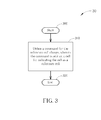
- FIG. 3 illustrates a flowchart of an exemplary process 30.
- the process 30 is utilized in the network (i.e. an eNB) for reference cell change.
- the process 30 can be compiled into the program code 214 and includes the following steps:
- the eNB designates a cell as the reference cell with a command sent on the cell.
- the command maybe a timing advance command.
- the eNB send a timing advance command to a cell of a timing advance group (TAG)
- TAG timing advance group
- the cell is determined to be a timing reference cell of the timing advance group for the UE.
- a deactivation timer for the new timing reference cell is started/restarted by the network.
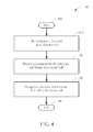
- Fig. 4 illustrates a flowchart of an exemplary process 40.
- the process 40 is utilized in the UE for reference cell change.
- the process 40 can be compiled into the program code 214 and includes the following steps:
- the UE when the current reference cell is the first cell, and the UE receives the command for the reference cell change on the second cell, the UE changes reference cell from the first cell to the second cell.
- the command may be a timing advance command. For example, if the current timing reference cell is cell A, and the UE receives a timing advance command on cell B, the UE changes the timing reference cell from cell A to cell B. Note that, after the UE changes to the cell B, a deactivation timer for the cell B is started/restarted.
- the present invention provides methods for reference cell change.
- a timing advance command sent on a cell is used for indicating the cell as the reference cell.
Landscapes
- Engineering & Computer Science (AREA)
- Computer Networks & Wireless Communication (AREA)
- Signal Processing (AREA)
- Mobile Radio Communication Systems (AREA)
Abstract
Description
- The application relates to a method utilized in a wireless communication system, and more particularly, to a method of reference cell change in a wireless communication system.
- Toward advanced high-speed wireless communication system, such as transmitting data in a higher peak data rate, LTE-Advanced system is standardized by the 3rd Generation Partnership Project (3GPP) as an enhancement of Long-Term Evolution (LTE) system. LTE-Advanced system targets faster switching between power states, improves performance at the cell edge, and includes subjects, such as bandwidth extension, coordinated multipoint transmission/reception (COMP), uplink multiple input multiple output (MIMO), etc.
- For bandwidth extension, carrier aggregation is introduced to the LTE-Advanced system for extension to wider bandwidth, where two or more component carriers are aggregated, for supporting wider transmission bandwidths (for example up to 100MHz) and for spectrum aggregation. According to carrier aggregation capability, multiple component carriers are aggregated into overall wider bandwidth, where a user equipment (UE) can establish multiple links corresponding to the multiple component carriers for simultaneously receiving and transmitting. In carrier aggregation, the UE only has one radio resource control (RRC) connection with the network. At RRC connection establishment/re-establishment/handover, one serving cell provides the Non-Access Stratum (NAS) mobility information, and at RRC connection re-establishment/handover, one serving cell provides the security input. This cell is referred to as a primary cell (PCell). In the downlink, the component carrier corresponding to the PCell is the Downlink Primary Component Carrier (DL PCC) while in the uplink it is the Uplink Primary Component Carrier (UL PCC). In addition, cells other than the PCell are named secondary cell (SCell).
- Since the UE may not need to use all of the configured cells (i.e. PCell and one or more SCells), only some SCells are activated, so as to save UE power. Note that, the PCell is always activated. Generally, an evolved Node-B (eNB) activates or deactivates a SCell by sending a signalling (e.g. a medium access control control element (MAC CE), or Activation/Deactivation command) to the UE. In addition, the UE starts a deactivation timer for a SCell when the SCell is activated, wherein the SCell is deactivated when the deactivation timer expires. In other words, the deactivation timer provides a period of time for SCell activation. Please note that, when the SCell is deactivated, the UE does not need to monitor physical downlink control channel (PDCCH) of the deactivated SCell. Further, the UE shall not transmit on UL-SCH on the deactivated SCell.
- As abovementioned, it is possible to configure a UE of a PCell and one SCell or more SCells. Therefore, multiple timing advance values, each for synchronization with a serving eNB on uplink timing for preventing signals transmitted from the UE from colliding with those sent from other UEs under the coverage of the eNB, are needed for PCell and SCell or more SCells. Note that, serving cells having uplink to which the same timing advance value applies are grouped in a timing advance group (TAG). Each TAG contains at least one serving cell with configured UL, and the mapping of each serving cell to a TAG is configured by the serving eNB. In order to realize uplink timing alignment, the UE maintains a time alignment timer (TAT) whose running state indicates that uplink transmission is still synchronized. TAT may be applied for a TAG.
- In carrier aggregation, a UE may apply information (i.e. parameter settings) to one cell by referring to the information observed from other cell, which is called reference cell in this disclosure. For example, the reference cell may be a timing reference cell. For the timing reference cell, if a UE uses the downlink timing of Cell #x as the timing reference for the Cell #y to derive an uplink transmission timing, then call Cell #x is the timing reference cell of the Cell #y.
- However, specification of LTE-Advanced system does not clearly define reference cell change. Thus, the network or the UE does not know how to configure or change a reference cell.
- This in mind, the application aims at providing a method of reference cell change in a wireless communication system in order to solve the abovementioned problems.
- This is achieved by a method of reference cell change according to claims 1 and 5. The dependent claims pertain to corresponding further developments and improvements.
- As will be seen more clearly from the detailed description following below, the claimed method of reference cell change for a network in a wireless communication system comprises utilizing a command for the reference cell change, wherein the command is sent on a cell for indicating the cell as a reference cell.
-
-
Fig. 1 illustrates a schematic diagram of an exemplary wireless communication system. -
Fig. 2 illustrates a schematic diagram of an exemplary communication device. -
Fig. 3 is a flowchart of an exemplary process. -
Fig. 4 is a flowchart of an exemplary process. - Please refer to
Fig. 1 , which is a schematic diagram of awireless communication system 10. Thewireless communication system 10 is a Long-Term Evolution advanced (LTE-Advanced) system or other mobile communication systems, and is briefly composed of a network and a plurality of user equipments (UEs). InFig. 1 , the network and the UEs are simply utilized for illustrating the structure of thewireless communication system 10. Practically, the network may be an evolved universal terrestrial radio access network (E-UTRAN) comprising a plurality of evolved base stations (eNBs). The UEs can be devices such as mobile phones, computer systems, a camera, a television, a hand-held video game device, a musical device, a wireless sensor, etc. In some applications, a UE may be a fixed computing device operating in a mobile environment, such as a bus, a train, an airplane, a boat, a car, etc. Besides, the network and the UE can be seen as a transmitter or receiver according to transmission direction, e.g., for uplink (UL), the UE is the transmitter and the network is the receiver, and for downlink (DL), the network is the transmitter and the UE is the receiver. -
Fig. 2 illustrates a schematic diagram of anexemplary communication device 20. Thecommunication device 20 can be the UE shown inFig. 1 , but is not limited herein. Thecommunication device 20 may include a processing means 200 such as a microprocessor or Application Specific Integrated Circuit (ASIC), astorage unit 210 and acommunication interfacing unit 220. Thestorage unit 210 may be any data storage device that can storeprogram code 214, for access by the processing means 200. Examples of thestorage unit 210 include but are not limited to a subscriber identity module (SIM), read-only memory (ROM), flash memory, random-access memory (RAM), CD-ROMs, magnetic tape, hard disk, and optical data storage device. Thecommunication interfacing unit 220 is preferably a radio transceiver and can exchange wireless signals with the network according to processing results of the processing means 200. - Please refer to
Fig. 3 , which illustrates a flowchart of anexemplary process 30. Theprocess 30 is utilized in the network (i.e. an eNB) for reference cell change. Theprocess 30 can be compiled into theprogram code 214 and includes the following steps: - Step 300: Start.
- Step 310: Utilize a command for the reference cell change, wherein the command is sent on a cell for indicating the cell as a reference cell.
- Step 320: End.
- According to the
process 30, the eNB designates a cell as the reference cell with a command sent on the cell. The command maybe a timing advance command. For example, if the eNB send a timing advance command to a cell of a timing advance group (TAG), the cell is determined to be a timing reference cell of the timing advance group for the UE. In addition, after the UE changes to the new timing reference cell, a deactivation timer for the new timing reference cell is started/restarted by the network. - Please refer to
Fig. 4 , which illustrates a flowchart of anexemplary process 40. Theprocess 40 is utilized in the UE for reference cell change. Theprocess 40 can be compiled into theprogram code 214 and includes the following steps: - Step 400: Start.
- Step 410: Be configured a first cell as a reference cell.
- Step 420: Receive a command for the reference cell change on a second cell.
- Step 430: Change the reference cell from the first cell to the second cell
- Step 440: End.
- According to the
process 40, when the current reference cell is the first cell, and the UE receives the command for the reference cell change on the second cell, the UE changes reference cell from the first cell to the second cell. The command may be a timing advance command. For example, if the current timing reference cell is cell A, and the UE receives a timing advance command on cell B, the UE changes the timing reference cell from cell A to cell B. Note that, after the UE changes to the cell B, a deactivation timer for the cell B is started/restarted. - In conclusion, the present invention provides methods for reference cell change. A timing advance command sent on a cell is used for indicating the cell as the reference cell.
Claims (8)
- A method of reference cell change for a network in a wireless communication system, characterized by the method comprising:utilizing a command for the reference cell change, wherein the command is sent on a cell for indicating the cell as a reference cell (310).
- The method of claim 1, characterized in that the reference cell is a timing reference cell.
- The method of claim 1, further comprising:starting or restarting a deactivation timer for the indicated cell after a communication device of the wireless communication system changes the reference cell to the indicated cell.
- The method of claim 1, characterized in that the command is a timing advance command.
- A method of reference cell change for a mobile device in a wireless communication system, characterized by the method comprising:being configured a first cell as a reference cell (410);receiving a command for the reference cell change on a second cell (420); andchanging the reference cell from the first cell to the second cell (430).
- The method of claim 5, characterized in that the reference cell is a timing reference cell.
- The method of claim 5, further comprising:starting or restarting a deactivation timer for the second cell after the mobile device changes the reference cell to the second cell.
- The method of claim 5, characterized in that the command is a timing advance command.
Applications Claiming Priority (5)
| Application Number | Priority Date | Filing Date | Title |
|---|---|---|---|
| US201261588997P | 2012-01-20 | 2012-01-20 | |
| US201261615032P | 2012-03-23 | 2012-03-23 | |
| US201261617681P | 2012-03-30 | 2012-03-30 | |
| US201261635868P | 2012-04-20 | 2012-04-20 | |
| US13/744,428 US20130188600A1 (en) | 2012-01-20 | 2013-01-18 | Method of Reference Cell Change |
Publications (2)
| Publication Number | Publication Date |
|---|---|
| EP2618606A2 true EP2618606A2 (en) | 2013-07-24 |
| EP2618606A3 EP2618606A3 (en) | 2013-10-30 |
Family
ID=47603385
Family Applications (1)
| Application Number | Title | Priority Date | Filing Date |
|---|---|---|---|
| EP13151993.6A Withdrawn EP2618606A3 (en) | 2012-01-20 | 2013-01-21 | Method of reference cell change |
Country Status (4)
| Country | Link |
|---|---|
| US (1) | US20130188600A1 (en) |
| EP (1) | EP2618606A3 (en) |
| CN (1) | CN103220661A (en) |
| TW (1) | TW201332326A (en) |
Cited By (1)
| Publication number | Priority date | Publication date | Assignee | Title |
|---|---|---|---|---|
| WO2025112680A1 (en) * | 2023-11-30 | 2025-06-05 | 华为技术有限公司 | Communication method and apparatus |
Families Citing this family (7)
| Publication number | Priority date | Publication date | Assignee | Title |
|---|---|---|---|---|
| KR102092579B1 (en) | 2011-08-22 | 2020-03-24 | 삼성전자 주식회사 | Method and apparatus for support multiple frequency band in a mobile communication system |
| EP2804416B1 (en) | 2012-01-09 | 2021-07-07 | Samsung Electronics Co., Ltd. | Method and apparatus for logging |
| EP2849501B1 (en) * | 2012-05-09 | 2020-09-30 | Samsung Electronics Co., Ltd. | Method and apparatus for controlling discontinuous reception in mobile communication system |
| KR102130375B1 (en) | 2012-05-09 | 2020-07-06 | 삼성전자 주식회사 | Method and apparatus for transmitting and receiving data in mobile communication system with multiple carrier |
| CN109982378A (en) | 2012-05-21 | 2019-07-05 | 三星电子株式会社 | Method and apparatus for transmitting and receiving data in mobile communication system |
| US9967076B2 (en) | 2015-04-16 | 2018-05-08 | Ofinno Technologies, Llc | Control signaling in a wireless device and wireless network |
| US10015757B2 (en) | 2015-09-14 | 2018-07-03 | Ofinno Technologies, Llc | Uplink timing advance configuration of a wireless device and base station |
Citations (1)
| Publication number | Priority date | Publication date | Assignee | Title |
|---|---|---|---|---|
| WO2012137984A1 (en) * | 2011-04-08 | 2012-10-11 | Sharp Kabushiki Kaisha | Devices for multi-group communications |
Family Cites Families (5)
| Publication number | Priority date | Publication date | Assignee | Title |
|---|---|---|---|---|
| US20110170422A1 (en) * | 2010-01-08 | 2011-07-14 | Rose Qingyang Hu | System and method for coordinated multi-point network operation to reduce radio link failure |
| CN102123425A (en) * | 2010-01-11 | 2011-07-13 | 中兴通讯股份有限公司 | Method and system for measurement, node B and user equipment (UE) |
| US9516559B2 (en) * | 2010-01-20 | 2016-12-06 | Blackberry Limited | Methods of performing cell change without receiving description of resources in a target cell |
| US9686814B2 (en) * | 2011-11-07 | 2017-06-20 | Industrial Technology Research Institute | Method of reference cell maintenance |
| DK2813025T3 (en) * | 2012-02-07 | 2017-02-06 | ERICSSON TELEFON AB L M (publ) | METHOD AND DEVICE FOR SENDING TIMING ADJUSTMENT |
-
2013
- 2013-01-18 US US13/744,428 patent/US20130188600A1/en not_active Abandoned
- 2013-01-21 CN CN2013100215460A patent/CN103220661A/en active Pending
- 2013-01-21 EP EP13151993.6A patent/EP2618606A3/en not_active Withdrawn
- 2013-01-21 TW TW102102225A patent/TW201332326A/en unknown
Patent Citations (1)
| Publication number | Priority date | Publication date | Assignee | Title |
|---|---|---|---|---|
| WO2012137984A1 (en) * | 2011-04-08 | 2012-10-11 | Sharp Kabushiki Kaisha | Devices for multi-group communications |
Cited By (1)
| Publication number | Priority date | Publication date | Assignee | Title |
|---|---|---|---|---|
| WO2025112680A1 (en) * | 2023-11-30 | 2025-06-05 | 华为技术有限公司 | Communication method and apparatus |
Also Published As
| Publication number | Publication date |
|---|---|
| TW201332326A (en) | 2013-08-01 |
| CN103220661A (en) | 2013-07-24 |
| EP2618606A3 (en) | 2013-10-30 |
| US20130188600A1 (en) | 2013-07-25 |
Similar Documents
| Publication | Publication Date | Title |
|---|---|---|
| US9191868B2 (en) | Method of timing reference management | |
| KR102794799B1 (en) | Method for transmitting downlink control information and base station, and method for receiving downlink control information, user device and storage medium | |
| EP2590352B1 (en) | Method of reference cell maintenance | |
| EP2557885B1 (en) | Method of handling random access procedure associated to cell deactivation | |
| US8923251B2 (en) | Method of handling uplink time alignment | |
| EP2696517B1 (en) | Efficient carrier activation in carrier aggregation based wireless communication systems | |
| CN104904174B (en) | Method and device for sending signals | |
| TWI786670B (en) | Methods and user equipment for wireless communication | |
| US9426840B2 (en) | Method of applying discontinuous reception operation and related communication device | |
| DK2813025T3 (en) | METHOD AND DEVICE FOR SENDING TIMING ADJUSTMENT | |
| US20130188600A1 (en) | Method of Reference Cell Change | |
| EP2547165B1 (en) | Method of handling random access procedure with deactivation timer | |
| EP2451222A1 (en) | Method of handling power headroom reporting for activated serving cell with configured uplink | |
| EP2418895B1 (en) | Method of handling power headroom reporting for uplink carrier aggregation and communication device thereof | |
| CN102761954A (en) | Uplink synchronization method and uplink synchronization system in multi-carrier communication system | |
| EP2645791B1 (en) | Method of preventing random access response collision | |
| KR20220047568A (en) | Method for transmitting and receiving signals in wireless communication system and apparatus therefor | |
| EP2645792B1 (en) | Method of random access response reception | |
| US20170094598A1 (en) | Device and Method of handling Power Preference | |
| CN113826412A (en) | Activation of secondary cells | |
| KR20250150527A (en) | Method for transmitting an uplink signal, user equipment, processing device, and storage medium, and method for receiving an uplink signal and base station |
Legal Events
| Date | Code | Title | Description |
|---|---|---|---|
| PUAI | Public reference made under article 153(3) epc to a published international application that has entered the european phase |
Free format text: ORIGINAL CODE: 0009012 |
|
| AK | Designated contracting states |
Kind code of ref document: A2 Designated state(s): AL AT BE BG CH CY CZ DE DK EE ES FI FR GB GR HR HU IE IS IT LI LT LU LV MC MK MT NL NO PL PT RO RS SE SI SK SM TR |
|
| AX | Request for extension of the european patent |
Extension state: BA ME |
|
| PUAL | Search report despatched |
Free format text: ORIGINAL CODE: 0009013 |
|
| AK | Designated contracting states |
Kind code of ref document: A3 Designated state(s): AL AT BE BG CH CY CZ DE DK EE ES FI FR GB GR HR HU IE IS IT LI LT LU LV MC MK MT NL NO PL PT RO RS SE SI SK SM TR |
|
| AX | Request for extension of the european patent |
Extension state: BA ME |
|
| RIC1 | Information provided on ipc code assigned before grant |
Ipc: H04W 36/00 20090101AFI20130924BHEP Ipc: H04W 56/00 20090101ALI20130924BHEP |
|
| 17P | Request for examination filed |
Effective date: 20140428 |
|
| RBV | Designated contracting states (corrected) |
Designated state(s): AL AT BE BG CH CY CZ DE DK EE ES FI FR GB GR HR HU IE IS IT LI LT LU LV MC MK MT NL NO PL PT RO RS SE SI SK SM TR |
|
| STAA | Information on the status of an ep patent application or granted ep patent |
Free format text: STATUS: EXAMINATION IS IN PROGRESS |
|
| 17Q | First examination report despatched |
Effective date: 20170306 |
|
| STAA | Information on the status of an ep patent application or granted ep patent |
Free format text: STATUS: THE APPLICATION IS DEEMED TO BE WITHDRAWN |
|
| 18D | Application deemed to be withdrawn |
Effective date: 20190402 |