EP2618590A1 - A personal care appliance kit - Google Patents
A personal care appliance kit Download PDFInfo
- Publication number
- EP2618590A1 EP2618590A1 EP13000233.0A EP13000233A EP2618590A1 EP 2618590 A1 EP2618590 A1 EP 2618590A1 EP 13000233 A EP13000233 A EP 13000233A EP 2618590 A1 EP2618590 A1 EP 2618590A1
- Authority
- EP
- European Patent Office
- Prior art keywords
- signal radiation
- window area
- front panel
- personal care
- appliance kit
- Prior art date
- Legal status (The legal status is an assumption and is not a legal conclusion. Google has not performed a legal analysis and makes no representation as to the accuracy of the status listed.)
- Granted
Links
- 230000005855 radiation Effects 0.000 claims abstract description 79
- XLYOFNOQVPJJNP-UHFFFAOYSA-N water Substances O XLYOFNOQVPJJNP-UHFFFAOYSA-N 0.000 claims abstract description 7
- 230000010287 polarization Effects 0.000 claims description 13
- 239000004973 liquid crystal related substance Substances 0.000 claims description 10
- 238000001514 detection method Methods 0.000 claims description 3
- 239000011521 glass Substances 0.000 description 3
- 230000003993 interaction Effects 0.000 description 3
- 239000000758 substrate Substances 0.000 description 3
- 230000003370 grooming effect Effects 0.000 description 2
- 239000007788 liquid Substances 0.000 description 2
- 239000011159 matrix material Substances 0.000 description 2
- 230000005540 biological transmission Effects 0.000 description 1
- 230000001419 dependent effect Effects 0.000 description 1
- 230000035515 penetration Effects 0.000 description 1
- 230000008054 signal transmission Effects 0.000 description 1
- 239000010409 thin film Substances 0.000 description 1
Images

Classifications
-
- G—PHYSICS
- G02—OPTICS
- G02F—OPTICAL DEVICES OR ARRANGEMENTS FOR THE CONTROL OF LIGHT BY MODIFICATION OF THE OPTICAL PROPERTIES OF THE MEDIA OF THE ELEMENTS INVOLVED THEREIN; NON-LINEAR OPTICS; FREQUENCY-CHANGING OF LIGHT; OPTICAL LOGIC ELEMENTS; OPTICAL ANALOGUE/DIGITAL CONVERTERS
- G02F1/00—Devices or arrangements for the control of the intensity, colour, phase, polarisation or direction of light arriving from an independent light source, e.g. switching, gating or modulating; Non-linear optics
- G02F1/01—Devices or arrangements for the control of the intensity, colour, phase, polarisation or direction of light arriving from an independent light source, e.g. switching, gating or modulating; Non-linear optics for the control of the intensity, phase, polarisation or colour
- G02F1/13—Devices or arrangements for the control of the intensity, colour, phase, polarisation or direction of light arriving from an independent light source, e.g. switching, gating or modulating; Non-linear optics for the control of the intensity, phase, polarisation or colour based on liquid crystals, e.g. single liquid crystal display cells
- G02F1/133—Constructional arrangements; Operation of liquid crystal cells; Circuit arrangements
- G02F1/1333—Constructional arrangements; Manufacturing methods
- G02F1/133308—Support structures for LCD panels, e.g. frames or bezels
-
- H—ELECTRICITY
- H04—ELECTRIC COMMUNICATION TECHNIQUE
- H04N—PICTORIAL COMMUNICATION, e.g. TELEVISION
- H04N5/00—Details of television systems
- H04N5/64—Constructional details of receivers, e.g. cabinets or dust covers
-
- A—HUMAN NECESSITIES
- A46—BRUSHWARE
- A46B—BRUSHES
- A46B15/00—Other brushes; Brushes with additional arrangements
- A46B15/0002—Arrangements for enhancing monitoring or controlling the brushing process
- A46B15/0038—Arrangements for enhancing monitoring or controlling the brushing process with signalling means
-
- A—HUMAN NECESSITIES
- A61—MEDICAL OR VETERINARY SCIENCE; HYGIENE
- A61C—DENTISTRY; APPARATUS OR METHODS FOR ORAL OR DENTAL HYGIENE
- A61C17/00—Devices for cleaning, polishing, rinsing or drying teeth, teeth cavities or prostheses; Saliva removers; Dental appliances for receiving spittle
- A61C17/16—Power-driven cleaning or polishing devices
-
- G—PHYSICS
- G02—OPTICS
- G02F—OPTICAL DEVICES OR ARRANGEMENTS FOR THE CONTROL OF LIGHT BY MODIFICATION OF THE OPTICAL PROPERTIES OF THE MEDIA OF THE ELEMENTS INVOLVED THEREIN; NON-LINEAR OPTICS; FREQUENCY-CHANGING OF LIGHT; OPTICAL LOGIC ELEMENTS; OPTICAL ANALOGUE/DIGITAL CONVERTERS
- G02F1/00—Devices or arrangements for the control of the intensity, colour, phase, polarisation or direction of light arriving from an independent light source, e.g. switching, gating or modulating; Non-linear optics
- G02F1/01—Devices or arrangements for the control of the intensity, colour, phase, polarisation or direction of light arriving from an independent light source, e.g. switching, gating or modulating; Non-linear optics for the control of the intensity, phase, polarisation or colour
- G02F1/13—Devices or arrangements for the control of the intensity, colour, phase, polarisation or direction of light arriving from an independent light source, e.g. switching, gating or modulating; Non-linear optics for the control of the intensity, phase, polarisation or colour based on liquid crystals, e.g. single liquid crystal display cells
- G02F1/1313—Devices or arrangements for the control of the intensity, colour, phase, polarisation or direction of light arriving from an independent light source, e.g. switching, gating or modulating; Non-linear optics for the control of the intensity, phase, polarisation or colour based on liquid crystals, e.g. single liquid crystal display cells specially adapted for a particular application
-
- H—ELECTRICITY
- H04—ELECTRIC COMMUNICATION TECHNIQUE
- H04N—PICTORIAL COMMUNICATION, e.g. TELEVISION
- H04N21/00—Selective content distribution, e.g. interactive television or video on demand [VOD]
- H04N21/40—Client devices specifically adapted for the reception of or interaction with content, e.g. set-top-box [STB]; Operations thereof
- H04N21/41—Structure of client; Structure of client peripherals
- H04N21/422—Input-only peripherals, i.e. input devices connected to specially adapted client devices, e.g. global positioning system [GPS]
- H04N21/42204—User interfaces specially adapted for controlling a client device through a remote control device; Remote control devices therefor
- H04N21/42206—User interfaces specially adapted for controlling a client device through a remote control device; Remote control devices therefor characterized by hardware details
- H04N21/4222—Remote control device emulator integrated into a non-television apparatus, e.g. a PDA, media center or smart toy
-
- A—HUMAN NECESSITIES
- A45—HAND OR TRAVELLING ARTICLES
- A45D—HAIRDRESSING OR SHAVING EQUIPMENT; EQUIPMENT FOR COSMETICS OR COSMETIC TREATMENTS, e.g. FOR MANICURING OR PEDICURING
- A45D26/00—Hair-singeing apparatus; Apparatus for removing superfluous hair, e.g. tweezers
- A45D2026/008—Details of apparatus for removing superfluous hair
-
- A—HUMAN NECESSITIES
- A46—BRUSHWARE
- A46B—BRUSHES
- A46B2200/00—Brushes characterized by their functions, uses or applications
- A46B2200/10—For human or animal care
- A46B2200/1066—Toothbrush for cleaning the teeth or dentures
Definitions
- the present invention is concerned with a personal care appliance kit comprising a display device and one of a oral care handle or shaver handle or epilator handle display devices and in particular with display devices having a receiver unit.
- IR window is typically placed in the housing of the display device.
- It is an object of the present disclosure to provide a personal care appliance kit comprising a display device and an oral care handle or a shaver handle or an epilator handle wherein said display device is in particular suitable for use in a wet or humid environment.
- a personal care appliance kit comprising a display device and one of an oral care handle or a shaver handle or an epilator handle said display device comprising: a continuous front panel; a window area being a part of the front panel, which window area is transmissible with respect to an infrared signal radiation; a display area being a part of the front panel, which display area is less transmissible with respect to the infrared signal radiation; and a receiver unit placed on a backside of the window area and adapted for receiving the infrared signal radiation from a transmitter unit for emitting the infrared signal radiation of said handle for indicating a handle use status, wherein the front panel is a liquid crystal display panel having at least one polarization filter layer and wherein the at least one polarization filter layer is provided with a cut-out in the window area.
- the present application is concerned with a display device that has a continuous front panel, a window area being a part of the front panel, which window area is transmissible with respect to a signal radiation, a display area being a part of the front panel, which display area is less transmissible with respect to the signal radiation, and a receiver unit placed on a backside of the window area and adapted for receiving the signal radiation.
- a display device is provided that does not require a further signal radiation receiver window and further the device can be made water proof by mounting only the front panel in a water-tight manner.
- the front panel is mounted in the display device in a water-proof manner.
- backside means the side opposite to the side intended for being visible by the viewer or, in other words, the side opposite to the side onto which the signal radiation impinges during operation.
- transmissible with respect to the signal radiation means that the window area allows transmission of signal radiation in an amount that the receiver unit can reliably detect signals conveyed by the signal radiation when the signal radiation has an intensity value above a certain signal radiation threshold level and is impinging onto the window area.
- the display area is less transmissible to the signal radiation and thus may not allow for reliably detecting presence of the signal radiation having an intensity value above the signal radiation threshold level and impinging onto the display area by a receiver unit placed behind the display area.
- the signal intensity of the signal radiation after it has passed the window area is about 25% higher than the signal intensity of the signal radiation after it has passed the display area (i.e. the signal ratio between the signal intensity in the window area and the signal intensity in the display area is at least about 1.25). In some embodiments, the signal ratio is about 1.5, 2, 2.5, 3, 3.5, 4, 4.5, 5, 6, 7, 8, 9, or 10 or higher.
- the front panel may be realized as a liquid crystal display (LCD) panel having at least one polarization filter that to a certain extend absorbs the signal radiation and wherein the polarization layer does not extend into the window area, i.e. the polarization filter may have a cut-out determining the window area.
- a liquid crystal layer of the LCD does not extend into the window area.
- the display area is at least essentially non-transmissible with respect to the signal radiation, where "essentially non-transmissible" here means that less than 10% of the impinging signal radiation transmits the display area without being absorbed.
- the window area is located at a border of the front panel. In some other embodiments, the window area may be located in a more central area of the front panel, in particular in case that the front panel area comprises areas where no information should be displayed, which areas could then be used to locate the window area.
- the window area may have a surface size between about 1 mm 2 and about 1000 mm 2 , in particular between about 10 mm 2 and about 100 mm 2 , and even more particularly between about 20 mm 2 and about 60 mm 2 .
- the display area has a surface size of between about 200 mm 2 and about 50.000 mm 2 . In some embodiments, the surface size of the window area is about or less than 10% of the surface size of the display area, in particular less than 9%, 8%, 7%, 6%, 5%, 4%, 3%, 2%, or 1%.
- the signal radiation may be infrared radiation, in particular near infrared radiation, but this should not be interpreted as limiting.
- Other radiation types could also be used as signal radiation, e.g. ultraviolet radiation, visible radiation or radio frequency radiation.
- the receiver unit and a control circuitry for controlling the display area are arranged on a single circuitry board.
- a kit comprising a display device as proposed and an electric device that comprises a transmitter unit for transmitting the signal radiation.
- the transmitter unit may have receiving functionality, i.e. may be realized as a transceiver unit.
- an additional receiver unit is arranged in the electric device.
- the electric device may in particular be realized as an oral hygiene device such as an electric or manually operated toothbrush, an electric flossing device, an interdental cleaner, a gum massaging device etc. or as a personal grooming device such as an electric shaver or a manually operated razor, an epilator, a skin massaging device etc.
- the electric device may be equipped to transmit certain information to the display device using a wireless transmission technology on basis of the signal radiation. Such information may range from simple information such as indicating the switching on/off of the electric device, the time of usage etc. to more complex information such as a life image of the area that is treated by the electric device, e.g. a life skin image.
- An LCD panel may be realized as an active matrix display comprising a matrix of thin film transistors (TFT) and/or with light emitting diode (LED) backlighting etc.
- TFT thin film transistors
- LED light emitting diode
- Fig. 1 is a schematic depiction of an example embodiment of a display device 1 as proposed.
- the display device has a front panel 10 that may be mounted into a housing 2.
- the front panel 10 is mounted into the housing 2 in a water tight manner such that during use of the display device 1 in a wet or humid environment penetration of liquids, such as water, or humidity into the device is at least partly inhibited and the interior of the display device 1 is thus better protected from damages originating from liquids or humidity.
- the front panel 10 has a window area 11 and a display area 12.
- the display area 12 is intended for displaying of information.
- the display area 12 is less transmissible with respect to a signal radiation than the window area 11.
- the display area may be essentially non-transmissible with respect to the signal radiation.
- the display device 1 may comprise interaction elements 20, 21 such as push buttons, capacitive switches etc. in order to switch the display device 1 on or off or to set parameters of the display device 1 etc.
- interaction elements 20, 21 such as push buttons, capacitive switches etc.
- the interaction elements may be arranged under a water tight protection cover that may be detachable for using the interaction elements.
- the front panel may be realized as a liquid crystal display (LCD) panel, as will be explained in more detail with respect to Fig. 2 .
- the signal radiation may be infrared radition, in other embodiments the signal radiation may be radio frequency radiation.
- Fig. 2 is a schematic cross sectional cut through a part of an example embodiment of a display device and may be taken along line A-A shown in Fig. 1 .
- This cross sectional cut is used for illustration of some features of an example embodiment of a display device as proposed and shall not be interpreted as being complete.
- Fig. 2 shows a cut through a part of a front panel 10 that is realized as a liquid crystal display (LCD) panel. Only some aspects of a LCD are shown as the general structure of a LCD panel is known to the skilled person.
- the front panel 10 comprises several layers.
- a liquid crystal layer 102 is sandwiched between two glass substrates 101 and on each one of the glass substrates 101 a polarization layer 100 is provided on an outer surface (i.e.
- the polarization layers 100 strongly absorb e.g. infrared radiation that may be used as signal radiation.
- the polarization layers 100 have cut-outs 1000 and 1001, respectively, which are in alignment in size and shape with each other with respect to a perpendicular axis that crosses the front panel 10 at 90 degrees. In some embodiments, an alignment in size and/or shape is not required as long as there is an overlap between the upper and the lower cut-outs such that signal radiation (indicated by wavy line and arrow 30 in Fig. 2 ) impinging vertically onto the front panel 10 could penetrate through the front panel without crossing a polarization layer 100.
- the area where the cut-outs of the polarization layer are in alignment determine the window area 11. In some embodiments, only a single polarization layer is provided and then the respective cut-out determines the window area.
- the remaining area of the front panel represents the display area 12. It is schematically shown in Fig. 2 that a circuitry board 200 is arranged underneath the front panel (where "underneath" means inside of the housing (shown in Fig. 1 ) of the display device, i.e. opposite to the front side 108 of the front panel 10).
- the circuitry board 200 has a mounting side 201 that faces the backside 109 of the front panel 10.
- a receiver unit 210 is mounted on the mounting side 201 of the circuitry board 200 at a location that is in alignment with the window area 11 with respect to a vertical axis though the front panel 10 (indicated by a dotted line in Fig. 2 ).
- the receiving unit 210 may be adapted for receiving the signal radiation 30 and for generating an output signal that may be proportional to the intensity of signal radiation 30 or that may be positive when the signal radiation intensity is above a predetermined threshold and zero when the signal radiation intensity is below the threshold value.
- the receiver unit may in particular be adapted to reliably output a detection signal when the intensity value of the signal radiation impinging vertically onto the front side of the front panel is above a signal radiation threshold value.
- Further circuitry components 220, 221 may be mounted on the circuitry board 200. These further circuitry components 220, 221 may for example be control circuitry components for controlling the display of information on the display area 12 of the front panel 10.
- the signal radiation is radio frequency radiation and the window area is then a part of the front panel that is kept free of any conductive layers that would absorb radio frequency radiation.
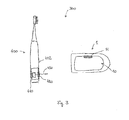
- Fig. 3 is a depiction of a kit comprising a display device 1 as proposed in the present application and an electric device 400 that in particular can be held in a user's hand.
- the electric device 400 may be realized as an oral hygiene device such as a toothbrush (as shown in Fig. 3 ) or a personal grooming device such as an electric shaver etc.
- the display device has a front panel 10 and the front panel comprises a window area 11 that is tranmissive with respect to a signal radiation.
- the electric device 400 may have a transmitter unit 410 for emitting the signal radiation 430.
- the electric device 400 may further have a housing 402 comprising a signal radiation window 420 that is transmissible with respect to the signal radiation 430 such that the signal radiation can exit the electric device 400.
- the signal radiation window 420 may in particular be placed such that it is located on the side of the electric device 400 that faces outwards from the user when the electric device 400 is held by the user during operation.
- the signal radiation emitted by the transmitter unit 410 can then conveniently reach the display device 1 that may be placed on a shelf or the like in the bathroom, e.g. under the mirror.
- the electric device may be equipped with a transceiver unit instead of a transmitter unit so that it can also receive signal radiation or the electric device may additionally be equipped with a receiver unit for receiving signal radiation.
- these units may be arranged to receive a signal radiation that is different to the signal radiation that the receiver unit in the display device, e.g. the receiver unit in the display device may be equipped to receive infrared radiation while the receiver unit/transceiver unit in the electric device may be quipped to receive radio frequency radiation.
Landscapes
- Physics & Mathematics (AREA)
- Engineering & Computer Science (AREA)
- Nonlinear Science (AREA)
- Health & Medical Sciences (AREA)
- Signal Processing (AREA)
- Multimedia (AREA)
- General Physics & Mathematics (AREA)
- Chemical & Material Sciences (AREA)
- Optics & Photonics (AREA)
- Crystallography & Structural Chemistry (AREA)
- Animal Behavior & Ethology (AREA)
- Veterinary Medicine (AREA)
- General Health & Medical Sciences (AREA)
- Life Sciences & Earth Sciences (AREA)
- Epidemiology (AREA)
- Dentistry (AREA)
- Public Health (AREA)
- Human Computer Interaction (AREA)
- Mathematical Physics (AREA)
- Devices For Indicating Variable Information By Combining Individual Elements (AREA)
Abstract
Description
- The present invention is concerned with a personal care appliance kit comprising a display device and one of a oral care handle or shaver handle or epilator handle display devices and in particular with display devices having a receiver unit.
- It is known that certain display devices such as flat display devices, e.g. flat TV devices, are equipped with a receiver window that is transmissible with respect to infrared (IR) radiation. The IR window is typically placed in the housing of the display device.
- It is also known to provide display devices that are intended for use in a wet or at least humid environment such as the bathroom and thus need to fulfill high standards with respect to water tightness.
- It is an object of the present disclosure to provide a personal care appliance kit comprising a display device and an oral care handle or a shaver handle or an epilator handle wherein said display device is in particular suitable for use in a wet or humid environment.
- In accordance with one aspect there is provided a personal care appliance kit comprising a display device and one of an oral care handle or a shaver handle or an epilator handle said display device comprising: a continuous front panel; a window area being a part of the front panel, which window area is transmissible with respect to an infrared signal radiation; a display area being a part of the front panel, which display area is less transmissible with respect to the infrared signal radiation; and a receiver unit placed on a backside of the window area and adapted for receiving the infrared signal radiation from a transmitter unit for emitting the infrared signal radiation of said handle for indicating a handle use status, wherein the front panel is a liquid crystal display panel having at least one polarization filter layer and wherein the at least one polarization filter layer is provided with a cut-out in the window area.
- Advantageous embodiments are set forth with the features of the
dependent claims 2 to 9. - The present disclosure is further elucidated by a detailed discussion of example embodiments and by reference to figures. In the figures
- Fig. 1
- is a schematic depiction of an example embodiment of a display device of said personal appliance kit as proposed;
- Fig. 2
- is a schematic cross sectional cut through said display device; and
- Fig. 3
- is a schematic depiction of a kit comprising a display device and an electric device.
- The present application is concerned with a display device that has a continuous front panel, a window area being a part of the front panel, which window area is transmissible with respect to a signal radiation, a display area being a part of the front panel, which display area is less transmissible with respect to the signal radiation, and a receiver unit placed on a backside of the window area and adapted for receiving the signal radiation. Thus, a display device is provided that does not require a further signal radiation receiver window and further the device can be made water proof by mounting only the front panel in a water-tight manner. Thus, in some embodiments, the front panel is mounted in the display device in a water-proof manner. In the context of the present disclosure, "backside" means the side opposite to the side intended for being visible by the viewer or, in other words, the side opposite to the side onto which the signal radiation impinges during operation.
- In the context of the present disclosure, "transmissible" with respect to the signal radiation means that the window area allows transmission of signal radiation in an amount that the receiver unit can reliably detect signals conveyed by the signal radiation when the signal radiation has an intensity value above a certain signal radiation threshold level and is impinging onto the window area. In contrast, the display area is less transmissible to the signal radiation and thus may not allow for reliably detecting presence of the signal radiation having an intensity value above the signal radiation threshold level and impinging onto the display area by a receiver unit placed behind the display area. In some embodiments, the signal intensity of the signal radiation after it has passed the window area is about 25% higher than the signal intensity of the signal radiation after it has passed the display area (i.e. the signal ratio between the signal intensity in the window area and the signal intensity in the display area is at least about 1.25). In some embodiments, the signal ratio is about 1.5, 2, 2.5, 3, 3.5, 4, 4.5, 5, 6, 7, 8, 9, or 10 or higher.
- In some embodiments, the front panel may be realized as a liquid crystal display (LCD) panel having at least one polarization filter that to a certain extend absorbs the signal radiation and wherein the polarization layer does not extend into the window area, i.e. the polarization filter may have a cut-out determining the window area. In some embodiments, a liquid crystal layer of the LCD does not extend into the window area. In some embodiments, the display area is at least essentially non-transmissible with respect to the signal radiation, where "essentially non-transmissible" here means that less than 10% of the impinging signal radiation transmits the display area without being absorbed.
- In some embodiments, the window area is located at a border of the front panel. In some other embodiments, the window area may be located in a more central area of the front panel, in particular in case that the front panel area comprises areas where no information should be displayed, which areas could then be used to locate the window area. Generally, in some embodiments, the window area may have a surface size between about 1 mm2 and about 1000 mm2, in particular between about 10 mm2 and about 100 mm2, and even more particularly between about 20 mm2 and about 60 mm2. In some embodiments, the display area has a surface size of between about 200 mm2 and about 50.000 mm2. In some embodiments, the surface size of the window area is about or less than 10% of the surface size of the display area, in particular less than 9%, 8%, 7%, 6%, 5%, 4%, 3%, 2%, or 1%.
- In some embodiments, the signal radiation may be infrared radiation, in particular near infrared radiation, but this should not be interpreted as limiting. Other radiation types could also be used as signal radiation, e.g. ultraviolet radiation, visible radiation or radio frequency radiation.
- In some embodiments, the receiver unit and a control circuitry for controlling the display area are arranged on a single circuitry board.
- In accordance with at least one aspect, a kit is provided that comprises a display device as proposed and an electric device that comprises a transmitter unit for transmitting the signal radiation. In some embodiments, the transmitter unit may have receiving functionality, i.e. may be realized as a transceiver unit. In some other embodiments, an additional receiver unit is arranged in the electric device. The electric device may in particular be realized as an oral hygiene device such as an electric or manually operated toothbrush, an electric flossing device, an interdental cleaner, a gum massaging device etc. or as a personal grooming device such as an electric shaver or a manually operated razor, an epilator, a skin massaging device etc. The electric device may be equipped to transmit certain information to the display device using a wireless transmission technology on basis of the signal radiation. Such information may range from simple information such as indicating the switching on/off of the electric device, the time of usage etc. to more complex information such as a life image of the area that is treated by the electric device, e.g. a life skin image.
- While the embodiments discussed with respect to the figures focus on a display device where the front panel is realized as a LCD panel, this should not be interpreted as limiting and other front panels could also be used such as an electronic ink panel or an organic light emitting diode (OLED) panel. An LCD panel may be realized as an active matrix display comprising a matrix of thin film transistors (TFT) and/or with light emitting diode (LED) backlighting etc.
- Features discussed in accordance with a particular embodiment shall be considered as individually disclosed and thus combinable with all other features described in the present application to the extent that such combination is technically possible and not explicitly excluded.
-
Fig. 1 is a schematic depiction of an example embodiment of adisplay device 1 as proposed. The display device has afront panel 10 that may be mounted into ahousing 2. In some embodiments, thefront panel 10 is mounted into thehousing 2 in a water tight manner such that during use of thedisplay device 1 in a wet or humid environment penetration of liquids, such as water, or humidity into the device is at least partly inhibited and the interior of thedisplay device 1 is thus better protected from damages originating from liquids or humidity. Thefront panel 10 has awindow area 11 and adisplay area 12. Thedisplay area 12 is intended for displaying of information. In accordance with the present disclosure, thedisplay area 12 is less transmissible with respect to a signal radiation than thewindow area 11. In some embodiments, the display area may be essentially non-transmissible with respect to the signal radiation. - In some embodiments, the
display device 1 may compriseinteraction elements display device 1 on or off or to set parameters of thedisplay device 1 etc. Instead of being arranged on the housing front, the interaction elements may be arranged under a water tight protection cover that may be detachable for using the interaction elements. - In some embodiments, the front panel may be realized as a liquid crystal display (LCD) panel, as will be explained in more detail with respect to
Fig. 2 . In some embodiments, the signal radiation may be infrared radition, in other embodiments the signal radiation may be radio frequency radiation. -
Fig. 2 is a schematic cross sectional cut through a part of an example embodiment of a display device and may be taken along line A-A shown inFig. 1 . This cross sectional cut is used for illustration of some features of an example embodiment of a display device as proposed and shall not be interpreted as being complete.Fig. 2 shows a cut through a part of afront panel 10 that is realized as a liquid crystal display (LCD) panel. Only some aspects of a LCD are shown as the general structure of a LCD panel is known to the skilled person. Thefront panel 10 comprises several layers. Aliquid crystal layer 102 is sandwiched between twoglass substrates 101 and on each one of the glass substrates 101 apolarization layer 100 is provided on an outer surface (i.e. the surface distal to the liquid crystal layer 102) of therespective glass substrate 100. The polarization layers 100 strongly absorb e.g. infrared radiation that may be used as signal radiation. InFig. 2 , the polarization layers 100 have cut-outs front panel 10 at 90 degrees. In some embodiments, an alignment in size and/or shape is not required as long as there is an overlap between the upper and the lower cut-outs such that signal radiation (indicated by wavy line andarrow 30 inFig. 2 ) impinging vertically onto thefront panel 10 could penetrate through the front panel without crossing apolarization layer 100. The area where the cut-outs of the polarization layer are in alignment determine thewindow area 11. In some embodiments, only a single polarization layer is provided and then the respective cut-out determines the window area. The remaining area of the front panel represents thedisplay area 12. It is schematically shown inFig. 2 that acircuitry board 200 is arranged underneath the front panel (where "underneath" means inside of the housing (shown inFig. 1 ) of the display device, i.e. opposite to thefront side 108 of the front panel 10). Thecircuitry board 200 has a mountingside 201 that faces thebackside 109 of thefront panel 10. Areceiver unit 210 is mounted on the mountingside 201 of thecircuitry board 200 at a location that is in alignment with thewindow area 11 with respect to a vertical axis though the front panel 10 (indicated by a dotted line inFig. 2 ). The receivingunit 210 may be adapted for receiving thesignal radiation 30 and for generating an output signal that may be proportional to the intensity ofsignal radiation 30 or that may be positive when the signal radiation intensity is above a predetermined threshold and zero when the signal radiation intensity is below the threshold value. The receiver unit may in particular be adapted to reliably output a detection signal when the intensity value of the signal radiation impinging vertically onto the front side of the front panel is above a signal radiation threshold value.Further circuitry components 220, 221 may be mounted on thecircuitry board 200. Thesefurther circuitry components 220, 221 may for example be control circuitry components for controlling the display of information on thedisplay area 12 of thefront panel 10. - In another embodiment, the signal radiation is radio frequency radiation and the window area is then a part of the front panel that is kept free of any conductive layers that would absorb radio frequency radiation.
-
Fig. 3 is a depiction of a kit comprising adisplay device 1 as proposed in the present application and anelectric device 400 that in particular can be held in a user's hand. Theelectric device 400 may be realized as an oral hygiene device such as a toothbrush (as shown inFig. 3 ) or a personal grooming device such as an electric shaver etc. The display device has afront panel 10 and the front panel comprises awindow area 11 that is tranmissive with respect to a signal radiation. Theelectric device 400 may have atransmitter unit 410 for emitting thesignal radiation 430. Theelectric device 400 may further have ahousing 402 comprising asignal radiation window 420 that is transmissible with respect to thesignal radiation 430 such that the signal radiation can exit theelectric device 400. Thesignal radiation window 420 may in particular be placed such that it is located on the side of theelectric device 400 that faces outwards from the user when theelectric device 400 is held by the user during operation. The signal radiation emitted by thetransmitter unit 410 can then conveniently reach thedisplay device 1 that may be placed on a shelf or the like in the bathroom, e.g. under the mirror. In some embodiments, the electric device may be equipped with a transceiver unit instead of a transmitter unit so that it can also receive signal radiation or the electric device may additionally be equipped with a receiver unit for receiving signal radiation. In an embodiment with a transceiver unit or an additional receiver unit, these units may be arranged to receive a signal radiation that is different to the signal radiation that the receiver unit in the display device, e.g. the receiver unit in the display device may be equipped to receive infrared radiation while the receiver unit/transceiver unit in the electric device may be quipped to receive radio frequency radiation. - The dimensions and values disclosed herein are not to be understood as being strictly limited to the exact numerical values recited. Instead, unless otherwise specified, each such dimension is intended to mean both the recited value and a functionally equivalent range surrounding that value. For example, a dimension disclosed as "40 mm" is intended to mean "about 40 mm."
Claims (9)
- A personal care appliance kit comprising a display device and an oral care handle or a shaver handle or an epilator handle said display device comprising:a continuous front panel;a window area being a part of the front panel, which window area is transmissible with respect to an infrared signal radiation;a display area being a part of the front panel, which display area is less transmissible with respect to the infrared signal radiation; anda receiver unit placed on a backside of the window area and adapted for receiving the infrared signal radiation from a transmitter unit for emitting the infrared signal radiation of said handle for indicating a handle use status,wherein the front panel is a liquid crystal display panel having at least one polarization filter layer and wherein the at least one polarization filter layer is provided with a cut-out in the window area.
- The personal care appliance kit in accordance with claim 1, wherein the ratio between the signal intensity of the signal radiation after having passed through the window area and of the signal intensity of the signal radiation after having passed through the display area is at least about 1.25 or higher.
- The personal care appliance kit in accordance with claim 2, wherein a liquid crystal layer of the liquid crystal display panel does not extend into the window area.
- The personal care appliance kit in accordance with any one of claims 1 to 3, wherein the window area is located at a border of the front panel.
- The personal care appliance kit in accordance with any one of claims 1 to 5, wherein the receiver unit and a control circuitry for controlling the display area are arranged on a single circuitry board.
- The personal care appliance kit in accordance with any one of claims 1 to 6, wherein the window area has a size of between about 1 mm2 to about 1000 mm2, in particular between about 10 mm2 and about 100 mm2.
- The personal care appliance kit in accordance with any one of claims 1 to 7, wherein the front panel is water tightly mounted into a housing of the display device.
- The personal care appliance kit in accordance with any one of claims 1 to 8, wherein the window area is structured such that it allows reliable detection of a signal conveyed by the signal radiation by the receiver unit when the signal radiation has an intensity value at the window area entrance side of above a signal radiation threshold value and is impinging essentially perpendicularly onto the window area and wherein the display area is structured to be less transmissible such that it would not allow reliable detection of the signal by the receiver unit.
- The personal care appliance kit in accordance with claim 8, wherein the receiver unit is arranged such that is allows for reliably detecting a signal conveyed by the signal radiation when the intensity value of the signal radiation impinging onto the window area is above the signal radiation threshold value.
Priority Applications (1)
| Application Number | Priority Date | Filing Date | Title |
|---|---|---|---|
| EP13000233.0A EP2618590B8 (en) | 2012-01-20 | 2013-01-17 | A personal care appliance kit |
Applications Claiming Priority (2)
| Application Number | Priority Date | Filing Date | Title |
|---|---|---|---|
| EP12152012 | 2012-01-20 | ||
| EP13000233.0A EP2618590B8 (en) | 2012-01-20 | 2013-01-17 | A personal care appliance kit |
Publications (3)
| Publication Number | Publication Date |
|---|---|
| EP2618590A1 true EP2618590A1 (en) | 2013-07-24 |
| EP2618590B1 EP2618590B1 (en) | 2014-12-31 |
| EP2618590B8 EP2618590B8 (en) | 2015-02-18 |
Family
ID=47749597
Family Applications (1)
| Application Number | Title | Priority Date | Filing Date |
|---|---|---|---|
| EP13000233.0A Not-in-force EP2618590B8 (en) | 2012-01-20 | 2013-01-17 | A personal care appliance kit |
Country Status (4)
| Country | Link |
|---|---|
| US (1) | US8947358B2 (en) |
| EP (1) | EP2618590B8 (en) |
| CN (1) | CN104054352A (en) |
| WO (1) | WO2013108212A1 (en) |
Families Citing this family (8)
| Publication number | Priority date | Publication date | Assignee | Title |
|---|---|---|---|---|
| USD708339S1 (en) * | 2012-07-05 | 2014-07-01 | Braun Gbmh | External display device for toothbrushes |
| EP2868293B1 (en) * | 2013-10-30 | 2017-08-30 | Trisa Holding AG | Electrically Operated Toothbrush for Tooth Care |
| EP3107485B2 (en) * | 2014-02-20 | 2024-01-24 | Braun GmbH | Oral care system |
| US11213120B2 (en) | 2016-11-14 | 2022-01-04 | Colgate-Palmolive Company | Oral care system and method |
| US11043141B2 (en) | 2016-11-14 | 2021-06-22 | Colgate-Palmolive Company | Oral care system and method |
| US11361672B2 (en) | 2016-11-14 | 2022-06-14 | Colgate-Palmolive Company | Oral care system and method |
| US10835028B2 (en) | 2016-11-14 | 2020-11-17 | Colgate-Palmolive Company | Oral care system and method |
| US10582764B2 (en) | 2016-11-14 | 2020-03-10 | Colgate-Palmolive Company | Oral care system and method |
Citations (6)
| Publication number | Priority date | Publication date | Assignee | Title |
|---|---|---|---|---|
| US20040239619A1 (en) * | 2002-08-02 | 2004-12-02 | Hitoshi Takahashi | Flat type image display device |
| JP2006157702A (en) * | 2004-11-30 | 2006-06-15 | Funai Electric Co Ltd | Remote controlled television receiver and remote controlled av apparatus |
| WO2007091130A1 (en) * | 2006-02-10 | 2007-08-16 | Nokia Corporation | A display module and method for fixing |
| US20080103267A1 (en) * | 2006-10-31 | 2008-05-01 | General Electric Company | Infrared transmissive thermoplastic composition |
| US20080109973A1 (en) * | 2006-11-15 | 2008-05-15 | Farrell Mark E | Personal care products and methods |
| EP2384720A2 (en) * | 2010-05-07 | 2011-11-09 | Braun GmbH | Toothbrush and method of wirelessly providing feedback related to its use |
Family Cites Families (6)
| Publication number | Priority date | Publication date | Assignee | Title |
|---|---|---|---|---|
| SG44037A1 (en) * | 1993-03-24 | 1997-11-14 | Koninkl Philips Electronics Nv | Electric toothbrush |
| JP2006155702A (en) | 2004-11-26 | 2006-06-15 | Fuji Photo Film Co Ltd | Device and method for tape traveling direction detection |
| KR20090077954A (en) * | 2006-11-15 | 2009-07-16 | 더 질레트 컴퍼니 | Oral Care Systems, Kits and Oral Care Devices |
| US8137109B2 (en) * | 2006-12-13 | 2012-03-20 | Colgate-Palmolive Company | Interactive oral care implement system |
| KR101382736B1 (en) | 2007-10-02 | 2014-04-08 | 엘지전자 주식회사 | Display apparatus |
| US20100283765A1 (en) * | 2008-03-03 | 2010-11-11 | Sharp Kabushiki Kaisha | Display device having optical sensors |
-
2013
- 2013-01-17 US US13/743,361 patent/US8947358B2/en not_active Expired - Fee Related
- 2013-01-17 CN CN201380005794.4A patent/CN104054352A/en active Pending
- 2013-01-17 EP EP13000233.0A patent/EP2618590B8/en not_active Not-in-force
- 2013-01-17 WO PCT/IB2013/050447 patent/WO2013108212A1/en not_active Ceased
Patent Citations (6)
| Publication number | Priority date | Publication date | Assignee | Title |
|---|---|---|---|---|
| US20040239619A1 (en) * | 2002-08-02 | 2004-12-02 | Hitoshi Takahashi | Flat type image display device |
| JP2006157702A (en) * | 2004-11-30 | 2006-06-15 | Funai Electric Co Ltd | Remote controlled television receiver and remote controlled av apparatus |
| WO2007091130A1 (en) * | 2006-02-10 | 2007-08-16 | Nokia Corporation | A display module and method for fixing |
| US20080103267A1 (en) * | 2006-10-31 | 2008-05-01 | General Electric Company | Infrared transmissive thermoplastic composition |
| US20080109973A1 (en) * | 2006-11-15 | 2008-05-15 | Farrell Mark E | Personal care products and methods |
| EP2384720A2 (en) * | 2010-05-07 | 2011-11-09 | Braun GmbH | Toothbrush and method of wirelessly providing feedback related to its use |
Also Published As
| Publication number | Publication date |
|---|---|
| EP2618590B1 (en) | 2014-12-31 |
| US20130188112A1 (en) | 2013-07-25 |
| US8947358B2 (en) | 2015-02-03 |
| CN104054352A (en) | 2014-09-17 |
| EP2618590B8 (en) | 2015-02-18 |
| WO2013108212A1 (en) | 2013-07-25 |
Similar Documents
| Publication | Publication Date | Title |
|---|---|---|
| EP2618590B1 (en) | A personal care appliance kit | |
| US10363327B2 (en) | Luminaire with white light LEDs and UV LEDs for lighting and disinfection | |
| JP6067570B2 (en) | Hygiene compliance module | |
| KR102131593B1 (en) | Apparatus for sterilizing kiosks with human body detection sensor and kiosk having the same | |
| US8964405B2 (en) | Portable electronic device sanitizer | |
| WO2016025957A1 (en) | Systems and methods for surface decontamination | |
| KR20110072601A (en) | Operation panel with sterilization function | |
| JP4018782B2 (en) | Radiation thermometer | |
| AU2648801A (en) | Touch contact switch with a LCD display | |
| WO2007137151A3 (en) | Ultrasonic cleaner | |
| JP2001194232A (en) | Optical sensor device and display device | |
| WO2017150381A1 (en) | Beauty treatment appliance | |
| JP3238156U (en) | Stain detector and laser radar | |
| JP2017153810A (en) | Beauty treatment instrument | |
| US20150359470A1 (en) | Hand-held measuring device | |
| WO2021053516A1 (en) | Ultra-violet sterilization system for a device surface | |
| KR20150003596U (en) | Body sensors and electronic timer built-in rechargeable UV disinfection unit | |
| CN117562691A (en) | Oral care device | |
| KR20200030211A (en) | Sterilizing apparatus | |
| JP2013094202A (en) | Backlight device | |
| CN221786746U (en) | Oral care device | |
| WO2017132498A1 (en) | Diagnostic medical device and methods of use thereof | |
| JP6869752B2 (en) | Beauty equipment | |
| TWI846179B (en) | Electronic device with display module and display module thereof | |
| KR102112134B1 (en) | Sterilizing apparatus |
Legal Events
| Date | Code | Title | Description |
|---|---|---|---|
| PUAI | Public reference made under article 153(3) epc to a published international application that has entered the european phase |
Free format text: ORIGINAL CODE: 0009012 |
|
| AK | Designated contracting states |
Kind code of ref document: A1 Designated state(s): AL AT BE BG CH CY CZ DE DK EE ES FI FR GB GR HR HU IE IS IT LI LT LU LV MC MK MT NL NO PL PT RO RS SE SI SK SM TR |
|
| AX | Request for extension of the european patent |
Extension state: BA ME |
|
| 17P | Request for examination filed |
Effective date: 20131217 |
|
| GRAP | Despatch of communication of intention to grant a patent |
Free format text: ORIGINAL CODE: EPIDOSNIGR1 |
|
| RIC1 | Information provided on ipc code assigned before grant |
Ipc: A45D 26/00 20060101ALI20140717BHEP Ipc: G02F 1/1333 20060101ALI20140717BHEP Ipc: H04N 21/422 20110101AFI20140717BHEP Ipc: A46B 15/00 20060101ALI20140717BHEP Ipc: G02F 1/13 20060101ALI20140717BHEP Ipc: A61C 17/16 20060101ALI20140717BHEP Ipc: H04N 5/64 20060101ALI20140717BHEP |
|
| INTG | Intention to grant announced |
Effective date: 20140804 |
|
| GRAS | Grant fee paid |
Free format text: ORIGINAL CODE: EPIDOSNIGR3 |
|
| GRAA | (expected) grant |
Free format text: ORIGINAL CODE: 0009210 |
|
| AK | Designated contracting states |
Kind code of ref document: B1 Designated state(s): AL AT BE BG CH CY CZ DE DK EE ES FI FR GB GR HR HU IE IS IT LI LT LU LV MC MK MT NL NO PL PT RO RS SE SI SK SM TR |
|
| REG | Reference to a national code |
Ref country code: CH Ref legal event code: EP Ref country code: GB Ref legal event code: FG4D |
|
| REG | Reference to a national code |
Ref country code: IE Ref legal event code: FG4D |
|
| REG | Reference to a national code |
Ref country code: AT Ref legal event code: REF Ref document number: 704970 Country of ref document: AT Kind code of ref document: T Effective date: 20150215 |
|
| REG | Reference to a national code |
Ref country code: DE Ref legal event code: R096 Ref document number: 602013000706 Country of ref document: DE Effective date: 20150219 |
|
| REG | Reference to a national code |
Ref country code: NL Ref legal event code: T3 |
|
| PG25 | Lapsed in a contracting state [announced via postgrant information from national office to epo] |
Ref country code: LT Free format text: LAPSE BECAUSE OF FAILURE TO SUBMIT A TRANSLATION OF THE DESCRIPTION OR TO PAY THE FEE WITHIN THE PRESCRIBED TIME-LIMIT Effective date: 20141231 Ref country code: NO Free format text: LAPSE BECAUSE OF FAILURE TO SUBMIT A TRANSLATION OF THE DESCRIPTION OR TO PAY THE FEE WITHIN THE PRESCRIBED TIME-LIMIT Effective date: 20150331 Ref country code: FI Free format text: LAPSE BECAUSE OF FAILURE TO SUBMIT A TRANSLATION OF THE DESCRIPTION OR TO PAY THE FEE WITHIN THE PRESCRIBED TIME-LIMIT Effective date: 20141231 |
|
| REG | Reference to a national code |
Ref country code: LT Ref legal event code: MG4D |
|
| PG25 | Lapsed in a contracting state [announced via postgrant information from national office to epo] |
Ref country code: LV Free format text: LAPSE BECAUSE OF FAILURE TO SUBMIT A TRANSLATION OF THE DESCRIPTION OR TO PAY THE FEE WITHIN THE PRESCRIBED TIME-LIMIT Effective date: 20141231 Ref country code: RS Free format text: LAPSE BECAUSE OF FAILURE TO SUBMIT A TRANSLATION OF THE DESCRIPTION OR TO PAY THE FEE WITHIN THE PRESCRIBED TIME-LIMIT Effective date: 20141231 Ref country code: GR Free format text: LAPSE BECAUSE OF FAILURE TO SUBMIT A TRANSLATION OF THE DESCRIPTION OR TO PAY THE FEE WITHIN THE PRESCRIBED TIME-LIMIT Effective date: 20150401 Ref country code: SE Free format text: LAPSE BECAUSE OF FAILURE TO SUBMIT A TRANSLATION OF THE DESCRIPTION OR TO PAY THE FEE WITHIN THE PRESCRIBED TIME-LIMIT Effective date: 20141231 Ref country code: HR Free format text: LAPSE BECAUSE OF FAILURE TO SUBMIT A TRANSLATION OF THE DESCRIPTION OR TO PAY THE FEE WITHIN THE PRESCRIBED TIME-LIMIT Effective date: 20141231 |
|
| REG | Reference to a national code |
Ref country code: AT Ref legal event code: MK05 Ref document number: 704970 Country of ref document: AT Kind code of ref document: T Effective date: 20141231 |
|
| PG25 | Lapsed in a contracting state [announced via postgrant information from national office to epo] |
Ref country code: SK Free format text: LAPSE BECAUSE OF FAILURE TO SUBMIT A TRANSLATION OF THE DESCRIPTION OR TO PAY THE FEE WITHIN THE PRESCRIBED TIME-LIMIT Effective date: 20141231 Ref country code: ES Free format text: LAPSE BECAUSE OF FAILURE TO SUBMIT A TRANSLATION OF THE DESCRIPTION OR TO PAY THE FEE WITHIN THE PRESCRIBED TIME-LIMIT Effective date: 20141231 Ref country code: RO Free format text: LAPSE BECAUSE OF FAILURE TO SUBMIT A TRANSLATION OF THE DESCRIPTION OR TO PAY THE FEE WITHIN THE PRESCRIBED TIME-LIMIT Effective date: 20141231 Ref country code: CZ Free format text: LAPSE BECAUSE OF FAILURE TO SUBMIT A TRANSLATION OF THE DESCRIPTION OR TO PAY THE FEE WITHIN THE PRESCRIBED TIME-LIMIT Effective date: 20141231 |
|
| PG25 | Lapsed in a contracting state [announced via postgrant information from national office to epo] |
Ref country code: PL Free format text: LAPSE BECAUSE OF FAILURE TO SUBMIT A TRANSLATION OF THE DESCRIPTION OR TO PAY THE FEE WITHIN THE PRESCRIBED TIME-LIMIT Effective date: 20141231 Ref country code: AT Free format text: LAPSE BECAUSE OF FAILURE TO SUBMIT A TRANSLATION OF THE DESCRIPTION OR TO PAY THE FEE WITHIN THE PRESCRIBED TIME-LIMIT Effective date: 20141231 Ref country code: IS Free format text: LAPSE BECAUSE OF FAILURE TO SUBMIT A TRANSLATION OF THE DESCRIPTION OR TO PAY THE FEE WITHIN THE PRESCRIBED TIME-LIMIT Effective date: 20150430 Ref country code: LU Free format text: LAPSE BECAUSE OF FAILURE TO SUBMIT A TRANSLATION OF THE DESCRIPTION OR TO PAY THE FEE WITHIN THE PRESCRIBED TIME-LIMIT Effective date: 20150117 |
|
| REG | Reference to a national code |
Ref country code: DE Ref legal event code: R097 Ref document number: 602013000706 Country of ref document: DE |
|
| PG25 | Lapsed in a contracting state [announced via postgrant information from national office to epo] |
Ref country code: EE Free format text: LAPSE BECAUSE OF FAILURE TO SUBMIT A TRANSLATION OF THE DESCRIPTION OR TO PAY THE FEE WITHIN THE PRESCRIBED TIME-LIMIT Effective date: 20141231 Ref country code: DK Free format text: LAPSE BECAUSE OF FAILURE TO SUBMIT A TRANSLATION OF THE DESCRIPTION OR TO PAY THE FEE WITHIN THE PRESCRIBED TIME-LIMIT Effective date: 20141231 Ref country code: MC Free format text: LAPSE BECAUSE OF FAILURE TO SUBMIT A TRANSLATION OF THE DESCRIPTION OR TO PAY THE FEE WITHIN THE PRESCRIBED TIME-LIMIT Effective date: 20141231 |
|
| REG | Reference to a national code |
Ref country code: IE Ref legal event code: MM4A |
|
| PLBE | No opposition filed within time limit |
Free format text: ORIGINAL CODE: 0009261 |
|
| STAA | Information on the status of an ep patent application or granted ep patent |
Free format text: STATUS: NO OPPOSITION FILED WITHIN TIME LIMIT |
|
| 26N | No opposition filed |
Effective date: 20151001 |
|
| REG | Reference to a national code |
Ref country code: FR Ref legal event code: PLFP Year of fee payment: 4 |
|
| PG25 | Lapsed in a contracting state [announced via postgrant information from national office to epo] |
Ref country code: IT Free format text: LAPSE BECAUSE OF FAILURE TO SUBMIT A TRANSLATION OF THE DESCRIPTION OR TO PAY THE FEE WITHIN THE PRESCRIBED TIME-LIMIT Effective date: 20141231 |
|
| PG25 | Lapsed in a contracting state [announced via postgrant information from national office to epo] |
Ref country code: IE Free format text: LAPSE BECAUSE OF NON-PAYMENT OF DUE FEES Effective date: 20150117 |
|
| PG25 | Lapsed in a contracting state [announced via postgrant information from national office to epo] |
Ref country code: SI Free format text: LAPSE BECAUSE OF FAILURE TO SUBMIT A TRANSLATION OF THE DESCRIPTION OR TO PAY THE FEE WITHIN THE PRESCRIBED TIME-LIMIT Effective date: 20141231 |
|
| PG25 | Lapsed in a contracting state [announced via postgrant information from national office to epo] |
Ref country code: BE Free format text: LAPSE BECAUSE OF FAILURE TO SUBMIT A TRANSLATION OF THE DESCRIPTION OR TO PAY THE FEE WITHIN THE PRESCRIBED TIME-LIMIT Effective date: 20141231 |
|
| REG | Reference to a national code |
Ref country code: CH Ref legal event code: PL |
|
| PG25 | Lapsed in a contracting state [announced via postgrant information from national office to epo] |
Ref country code: CH Free format text: LAPSE BECAUSE OF NON-PAYMENT OF DUE FEES Effective date: 20160131 Ref country code: LI Free format text: LAPSE BECAUSE OF NON-PAYMENT OF DUE FEES Effective date: 20160131 |
|
| PG25 | Lapsed in a contracting state [announced via postgrant information from national office to epo] |
Ref country code: MT Free format text: LAPSE BECAUSE OF FAILURE TO SUBMIT A TRANSLATION OF THE DESCRIPTION OR TO PAY THE FEE WITHIN THE PRESCRIBED TIME-LIMIT Effective date: 20141231 |
|
| REG | Reference to a national code |
Ref country code: FR Ref legal event code: PLFP Year of fee payment: 5 |
|
| PGFP | Annual fee paid to national office [announced via postgrant information from national office to epo] |
Ref country code: GB Payment date: 20161228 Year of fee payment: 5 |
|
| PGFP | Annual fee paid to national office [announced via postgrant information from national office to epo] |
Ref country code: NL Payment date: 20170109 Year of fee payment: 5 |
|
| PGFP | Annual fee paid to national office [announced via postgrant information from national office to epo] |
Ref country code: DE Payment date: 20170131 Year of fee payment: 5 Ref country code: FR Payment date: 20170103 Year of fee payment: 5 |
|
| PG25 | Lapsed in a contracting state [announced via postgrant information from national office to epo] |
Ref country code: HU Free format text: LAPSE BECAUSE OF FAILURE TO SUBMIT A TRANSLATION OF THE DESCRIPTION OR TO PAY THE FEE WITHIN THE PRESCRIBED TIME-LIMIT; INVALID AB INITIO Effective date: 20130117 Ref country code: BG Free format text: LAPSE BECAUSE OF FAILURE TO SUBMIT A TRANSLATION OF THE DESCRIPTION OR TO PAY THE FEE WITHIN THE PRESCRIBED TIME-LIMIT Effective date: 20141231 |
|
| PG25 | Lapsed in a contracting state [announced via postgrant information from national office to epo] |
Ref country code: CY Free format text: LAPSE BECAUSE OF FAILURE TO SUBMIT A TRANSLATION OF THE DESCRIPTION OR TO PAY THE FEE WITHIN THE PRESCRIBED TIME-LIMIT Effective date: 20141231 |
|
| PG25 | Lapsed in a contracting state [announced via postgrant information from national office to epo] |
Ref country code: TR Free format text: LAPSE BECAUSE OF FAILURE TO SUBMIT A TRANSLATION OF THE DESCRIPTION OR TO PAY THE FEE WITHIN THE PRESCRIBED TIME-LIMIT Effective date: 20141231 |
|
| PG25 | Lapsed in a contracting state [announced via postgrant information from national office to epo] |
Ref country code: SM Free format text: LAPSE BECAUSE OF FAILURE TO SUBMIT A TRANSLATION OF THE DESCRIPTION OR TO PAY THE FEE WITHIN THE PRESCRIBED TIME-LIMIT Effective date: 20141231 |
|
| PG25 | Lapsed in a contracting state [announced via postgrant information from national office to epo] |
Ref country code: MK Free format text: LAPSE BECAUSE OF FAILURE TO SUBMIT A TRANSLATION OF THE DESCRIPTION OR TO PAY THE FEE WITHIN THE PRESCRIBED TIME-LIMIT Effective date: 20141231 |
|
| PG25 | Lapsed in a contracting state [announced via postgrant information from national office to epo] |
Ref country code: PT Free format text: LAPSE BECAUSE OF FAILURE TO SUBMIT A TRANSLATION OF THE DESCRIPTION OR TO PAY THE FEE WITHIN THE PRESCRIBED TIME-LIMIT Effective date: 20141231 |
|
| REG | Reference to a national code |
Ref country code: DE Ref legal event code: R119 Ref document number: 602013000706 Country of ref document: DE |
|
| REG | Reference to a national code |
Ref country code: NL Ref legal event code: MM Effective date: 20180201 |
|
| GBPC | Gb: european patent ceased through non-payment of renewal fee |
Effective date: 20180117 |
|
| PG25 | Lapsed in a contracting state [announced via postgrant information from national office to epo] |
Ref country code: DE Free format text: LAPSE BECAUSE OF NON-PAYMENT OF DUE FEES Effective date: 20180801 Ref country code: FR Free format text: LAPSE BECAUSE OF NON-PAYMENT OF DUE FEES Effective date: 20180131 Ref country code: AL Free format text: LAPSE BECAUSE OF FAILURE TO SUBMIT A TRANSLATION OF THE DESCRIPTION OR TO PAY THE FEE WITHIN THE PRESCRIBED TIME-LIMIT Effective date: 20141231 |
|
| REG | Reference to a national code |
Ref country code: FR Ref legal event code: ST Effective date: 20180928 |
|
| PG25 | Lapsed in a contracting state [announced via postgrant information from national office to epo] |
Ref country code: GB Free format text: LAPSE BECAUSE OF NON-PAYMENT OF DUE FEES Effective date: 20180117 Ref country code: NL Free format text: LAPSE BECAUSE OF NON-PAYMENT OF DUE FEES Effective date: 20180201 |