EP2618452A2 - An electronic device with source identification unit - Google Patents
An electronic device with source identification unit Download PDFInfo
- Publication number
- EP2618452A2 EP2618452A2 EP13150602.4A EP13150602A EP2618452A2 EP 2618452 A2 EP2618452 A2 EP 2618452A2 EP 13150602 A EP13150602 A EP 13150602A EP 2618452 A2 EP2618452 A2 EP 2618452A2
- Authority
- EP
- European Patent Office
- Prior art keywords
- electronic device
- voltage
- adapter
- accordance
- power source
- Prior art date
- Legal status (The legal status is an assumption and is not a legal conclusion. Google has not performed a legal analysis and makes no representation as to the accuracy of the status listed.)
- Granted
Links
Images
Classifications
-
- H—ELECTRICITY
- H02—GENERATION; CONVERSION OR DISTRIBUTION OF ELECTRIC POWER
- H02J—ELECTRIC POWER NETWORKS; CIRCUIT ARRANGEMENTS OR SYSTEMS FOR SUPPLYING OR DISTRIBUTING ELECTRIC POWER; SYSTEMS FOR STORING ELECTRIC ENERGY
- H02J7/00—Circuit arrangements for charging or discharging batteries or for supplying loads from batteries
- H02J7/485—Circuit arrangements for charging or discharging batteries or for supplying loads from batteries with provisions for charging different types of batteries
Definitions
- the present invention is related to the electronic devices which can be powered from different power sources and to the operation methods of such electronic devices.
- Electronic devices can be used in different environments. According to the environment the electronic device is used, power source of the electronic device may change. For example, for household use, an electronic device can be energised from mains plug directly or by an adaptor. On the other hand, if the device is to be used in a vehicle such as an automobile, electronic device can be energised from the DC network of the vehicle via a DC power plug. Especially in mobile devices (such as mobile televisions, mobile phones etc.), in order to reduce the number of input terminals, there is only one power input which can be connected to either an adapter (preferably a DC adapter) or a power plug of a vehicle. With said power input, electronic device can be energised from any available power source.
- an adapter preferably a DC adapter
- Patent document no EP0551080A2 discloses an electronic device which can be energised from different power sources. According to this document, detection of power source is performed by comparing the voltage levels of the connected power sources. For instance, when an AC adapter is connected, input voltage is read as 0 volt and when a car battery is connected, input voltage is read as 12 V. However, in this document, a DC adapter and a battery, which both have same voltage level; can not be differentiated from each other.
- Another patent document no US5506490A discloses a method and an apparatus for determining external power supply type. According to this document, type of the power supply is detected by detecting the output resistance of the power source. However, this document also does not disclose detecting different source types with same voltage level (for example a car battery with 12 V DC output and a DC adapter with 12 V output).
- an electronic device which detects the type of power source, and operation method for said electronic device.
- Said device comprises at least one power input (1), which can be connected to either a DC adapter or a DC power source; at least one main board, which is powered from said power input (1); at least one filtering means (3), which filters the voltage fed through said power input (1); at least one detection means (4), which detects the high frequency components of the filtered voltage and sends signal to said main board with respect to the existence of said high frequency components.
- Said main board further comprises means for adjusting settings of the electronic device in relation to signal sent by said detection means.
- Said method comprises the steps of, powering said electronic device; filtering input voltage fed through said power input (1) by said filtering means; analyzing voltage and frequency characteristic of the filtered voltage in said detection means; checking whether analysed voltage contains any high frequency component whose frequency is higher than a threshold frequency; if there is at least one high frequency component, identifying the power source as a DC adapter and adjusting electronic device settings in accordance with requirements of a DC adapter and if no high frequency component is detected, identifying the power source as a DC source and adjusting electronic device settings in accordance with requirements of a DC source.
- electronic device can be used efficiently with different power sources. Furthermore, according to the detected power source of the electronic device, user settings of the electronic device can be adjusted.
- An object of the present invention is to provide an electronic device in which type of the power source is detected.
- Another object of the present invention is to provide an operation method for an electronic device, which enables detection of type of power source.
- Another object of the present invention is to provide an operation method for an electronic device which enables operation of said device efficiently with different type of power sources.
- Another object of the present invention is to provide an electronic device, in which settings of said device to be loaded automatically according to the type of the detected power source.
- Another object of the present invention is to provide an operation method for an electronic device, which enables settings of said device to be loaded automatically according to the type of the detected power source.
- the reference numbers as used in figures may possess the following meanings; Power input (1) Main board (2) Filtering means (3) Detection means (4) Powering (101) Filtering (102) Analyse voltage (103) Check high frequency components (104) Adjust settings in accordance with DC adapter settings (105) Adjust settings in accordance with DC source settings (106)
- Electronic devices especially mobile devices, can be used in different environments and due to availability in the environment, they can be powered from different power sources.
- protection settings of the electronic device should be adjusted according to power source.
- an electronic device which detects type of power source and working method of said device is provided.
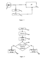
- FIG. 1 shows a block diagram of the electronic device of the present invention.
- Said electronic device comprises at least one power input (1), which can be connected to either a DC adapter or a DC power source; at least one main board (2), which is powered from said power input (1); at least one filtering means (3), which filters the voltage fed through said power input (1) to remove the DC component of said voltage; and at least one detection means (4), which detects the high frequency components of the filtered voltage, which is higher than a predetermined frequency, and sends signal to said main board (2) with respect to the existence of said high frequency components.
- said main board (2) comprises means for adjusting at least one setting of the electronic device in relation to signal sent by said detection means (4).
- Said filtering means (3) may comprise at least one band pass filter.
- FIG. 2 A flow chart of the operation method of electronic device of the present invention is given in figure 2 .
- the electronic device when the electronic device is powered (101) (for example when the device is connected to a power source or when a power button of the electronic device is depressed, powering on the device), input voltage fed through said power input (1) is filtered by filtering means (3) (102).
- filtering means (3) In the detection means (4), voltage and frequency characteristic of the filtered voltage is analysed (103). Then, it is checked whether analysed voltage contains any high frequency component whose frequency is higher than a threshold frequency (104).
- Said threshold frequency can be a predetermined frequency, which is determined by manufacturer, or said frequency can be determined by the user.
- the power source is identified as a DC adapter and electronic device settings are adjusted in accordance with requirements of a DC adapter (105). If no high frequency component is detected, the power source is identified as a DC source and electronic device settings are adjusted in accordance with requirements of a DC source (106).
- Modern DC adapters which generally use switch mode topologies, generate DC output voltage which has almost a constant voltage level.
- this output voltage contains high frequency components with small amplitudes, which arise due to switching manner of the supply.
- these components are negligible when compared to DC component of the output voltage, when the output voltage is filtered to remove DC component of the output voltage, said components can be detected.
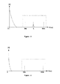
- a high frequency component can be seen.
- This component can be detected by said detection means (4).
- a battery supplies an output with no continuous high frequency components.
- no high frequency components is detected. In the present invention, by detecting said high frequency, type of the power source is detected.
- said means for adjusting settings of the electronic device comprises at least one protection circuit, which blocks the noises of the input voltage.
- Said protection circuit can be a low pass filter, voltage and/or current snubber or any voltage limiting circuit.
- device may further comprise means for by-passing (disabling) said protection circuit in accordance with detected power source.
- a protection method against the unwanted voltage peaks, inrush currents and/or noises of the power input is performed.
- electronic device turn on may be delayed.
- the electronic device is a television, sound and display may be outputted with a predefined delay in order to provide a better quality.
- the electronic device settings are adjusted in accordance with an AC power source (105)
- electronic device is started without a protection method. In other words, electronic device is started with best quality settings (and preferably without delay).
- electronic device is used with most efficient settings for different types of power sources.
- said electronic device is a mobile television which is suitable for household use with a DC adapter and in a vehicle powered via DC power source.
- a mobile television which is suitable for household use with a DC adapter and in a vehicle powered via DC power source.
- user settings such as display and sound settings
- home environment for example contrast of display and sound are adjusted to a high level.
- a DC power source 106
- user settings of the mobile television are adjusted in accordance with the environment of the vehicle (i.e. contrast of display and sound are adjusted to a low level).
- environment settings can be determined by user or can be predefined by the manufacturer.
- the step of checking high frequency components (104) if at least one high frequency component is detected, it is checked that whether detected component exist for a predetermined time or not. If detected component exists for a predetermined time (i.e. said component is continuous), then the power source is identified as a DC adapter and electronic device settings are adjusted accordingly (105). If said component does not exist for said predetermined time, the power source is identified as a DC source and electronic device settings are adjusted in accordance with requirements of a DC source (106). With this additional step, in a DC network when a noise with high frequency occurs, identifying the power source as DC adapter erroneously is prevented, since said noise is not continuous with a constant frequency. Said predetermined time may be determined by manufacturer or by the user.
- electronic device can be used efficiently with different power sources. Furthermore, according to the detected power source of the electronic device, user settings of the electronic device can be adjusted.
Landscapes
- Engineering & Computer Science (AREA)
- Power Engineering (AREA)
- Dc-Dc Converters (AREA)
- Power Sources (AREA)
- Direct Current Feeding And Distribution (AREA)
Abstract
Description
- The present invention is related to the electronic devices which can be powered from different power sources and to the operation methods of such electronic devices.
- Electronic devices can be used in different environments. According to the environment the electronic device is used, power source of the electronic device may change. For example, for household use, an electronic device can be energised from mains plug directly or by an adaptor. On the other hand, if the device is to be used in a vehicle such as an automobile, electronic device can be energised from the DC network of the vehicle via a DC power plug. Especially in mobile devices (such as mobile televisions, mobile phones etc.), in order to reduce the number of input terminals, there is only one power input which can be connected to either an adapter (preferably a DC adapter) or a power plug of a vehicle. With said power input, electronic device can be energised from any available power source. When an electronic device is energised from a DC adapter, since DC adapter outputs almost a DC voltage constantly, electronic device works with no problem. On the other hand, when the electronic device is energised from a power plug of a vehicle, since the plug is energized from a main electrical network within the vehicle, which feeds high power components (i.e. headlights, igniters) and is also fed from a generator driven by the engine of the vehicle, electronic device may not work efficiently due to electrical instability of said electrical network which may arise from several factors such as noises generated by components connected to the network, inrush currents of the components and AC component of generator output current. Furthermore, because of said unwanted voltage peaks, inrush currents and/or noises, electronic device may be damaged due to electrical instability, for instance at the turn-on of the device. In order to prevent such inefficiency and breakdown of the electronic device, some protection methods, such as turning on the device with a predefined time delay, are used. However, said protection methods also reduce the efficiency of the electronic device. When the electronic device is energised from a DC network, such efficiency reduction is not important since the electronic device still works efficiently as compared to being used without a protection. On the other hand, when the electronic device is to be energised from an adapter, efficiency of the electronic device decreases as compared to being used without protection. Thus, in order to use electronic device efficiently in all conditions, power source of the electronic device should be detected.
- In order to detect power input source of the electronic devices, various methods are used in the known art. Patent document no
EP0551080A2 discloses an electronic device which can be energised from different power sources. According to this document, detection of power source is performed by comparing the voltage levels of the connected power sources. For instance, when an AC adapter is connected, input voltage is read as 0 volt and when a car battery is connected, input voltage is read as 12 V. However, in this document, a DC adapter and a battery, which both have same voltage level; can not be differentiated from each other. - Another patent document no
US5506490A discloses a method and an apparatus for determining external power supply type. According to this document, type of the power supply is detected by detecting the output resistance of the power source. However, this document also does not disclose detecting different source types with same voltage level (for example a car battery with 12 V DC output and a DC adapter with 12 V output). - With the present invention, an electronic device, which detects the type of power source, and operation method for said electronic device is provided. Said device comprises at least one power input (1), which can be connected to either a DC adapter or a DC power source; at least one main board, which is powered from said power input (1); at least one filtering means (3), which filters the voltage fed through said power input (1); at least one detection means (4), which detects the high frequency components of the filtered voltage and sends signal to said main board with respect to the existence of said high frequency components. Said main board further comprises means for adjusting settings of the electronic device in relation to signal sent by said detection means.
- Said method comprises the steps of, powering said electronic device; filtering input voltage fed through said power input (1) by said filtering means; analyzing voltage and frequency characteristic of the filtered voltage in said detection means; checking whether analysed voltage contains any high frequency component whose frequency is higher than a threshold frequency; if there is at least one high frequency component, identifying the power source as a DC adapter and adjusting electronic device settings in accordance with requirements of a DC adapter and if no high frequency component is detected, identifying the power source as a DC source and adjusting electronic device settings in accordance with requirements of a DC source.
- With this electronic device and operation method, electronic device can be used efficiently with different power sources. Furthermore, according to the detected power source of the electronic device, user settings of the electronic device can be adjusted.
- An object of the present invention is to provide an electronic device in which type of the power source is detected.
- Another object of the present invention is to provide an operation method for an electronic device, which enables detection of type of power source.
- Another object of the present invention is to provide an operation method for an electronic device which enables operation of said device efficiently with different type of power sources.
- Another object of the present invention is to provide an electronic device, in which settings of said device to be loaded automatically according to the type of the detected power source.
- Another object of the present invention is to provide an operation method for an electronic device, which enables settings of said device to be loaded automatically according to the type of the detected power source.
-
-
Figure 1 shows a block diagram of the electronic device of the present invention. -
Figure 2 shows flowchart of the operation method of the electronic device of the present invention. -
Figure 3 shows voltage-frequency graph of filtered output of a DC adapter. -
Figure 4 shows voltage-frequency graph of filtered output of a battery. - The reference numbers as used in figures may possess the following meanings;
Power input (1) Main board (2) Filtering means (3) Detection means (4) Powering (101) Filtering (102) Analyse voltage (103) Check high frequency components (104) Adjust settings in accordance with DC adapter settings (105) Adjust settings in accordance with DC source settings (106) - Electronic devices, especially mobile devices, can be used in different environments and due to availability in the environment, they can be powered from different power sources. In order to use said electronic device with different power sources efficiently, protection settings of the electronic device should be adjusted according to power source. Thus, with the present invention, an electronic device which detects type of power source and working method of said device is provided.
-
Figure 1 shows a block diagram of the electronic device of the present invention. Said electronic device comprises at least one power input (1), which can be connected to either a DC adapter or a DC power source; at least one main board (2), which is powered from said power input (1); at least one filtering means (3), which filters the voltage fed through said power input (1) to remove the DC component of said voltage; and at least one detection means (4), which detects the high frequency components of the filtered voltage, which is higher than a predetermined frequency, and sends signal to said main board (2) with respect to the existence of said high frequency components. Furthermore, said main board (2) comprises means for adjusting at least one setting of the electronic device in relation to signal sent by said detection means (4). Said filtering means (3) may comprise at least one band pass filter. - A flow chart of the operation method of electronic device of the present invention is given in
figure 2 . According to said method, when the electronic device is powered (101) (for example when the device is connected to a power source or when a power button of the electronic device is depressed, powering on the device), input voltage fed through said power input (1) is filtered by filtering means (3) (102). In the detection means (4), voltage and frequency characteristic of the filtered voltage is analysed (103). Then, it is checked whether analysed voltage contains any high frequency component whose frequency is higher than a threshold frequency (104). Said threshold frequency can be a predetermined frequency, which is determined by manufacturer, or said frequency can be determined by the user. If there is at least one high frequency component, the power source is identified as a DC adapter and electronic device settings are adjusted in accordance with requirements of a DC adapter (105). If no high frequency component is detected, the power source is identified as a DC source and electronic device settings are adjusted in accordance with requirements of a DC source (106). - Modern DC adapters, which generally use switch mode topologies, generate DC output voltage which has almost a constant voltage level. However, this output voltage contains high frequency components with small amplitudes, which arise due to switching manner of the supply. Although these components are negligible when compared to DC component of the output voltage, when the output voltage is filtered to remove DC component of the output voltage, said components can be detected. As given in
figure 3 , when the output of a DC adapter is filtered with a band pass filter, due to switching nature of the adapter, a high frequency component can be seen. This component can be detected by said detection means (4). On the other hand, a battery supplies an output with no continuous high frequency components. As given infigure 4 , when the output of a battery is filtered, no high frequency components is detected. In the present invention, by detecting said high frequency, type of the power source is detected. - In a preferred embodiment of the present invention, said means for adjusting settings of the electronic device comprises at least one protection circuit, which blocks the noises of the input voltage. Said protection circuit can be a low pass filter, voltage and/or current snubber or any voltage limiting circuit. In another embodiment of the present invention, device may further comprise means for by-passing (disabling) said protection circuit in accordance with detected power source.
- In a preferred embodiment of the present invention, when the electronic device settings are adjusted in accordance with a DC power source usage (106), a protection method against the unwanted voltage peaks, inrush currents and/or noises of the power input is performed. In said protection method, electronic device turn on may be delayed. For example, when the electronic device is a television, sound and display may be outputted with a predefined delay in order to provide a better quality. On the other hand, when the electronic device settings are adjusted in accordance with an AC power source (105), electronic device is started without a protection method. In other words, electronic device is started with best quality settings (and preferably without delay). Thus, according to the present invention, electronic device is used with most efficient settings for different types of power sources.
- In another preferred embodiment of the present invention, said electronic device is a mobile television which is suitable for household use with a DC adapter and in a vehicle powered via DC power source. In this embodiment, when the mobile television settings are adjusted in accordance with an AC power source (105), user settings (such as display and sound settings) of the mobile television are adjusted according to home environment (for example contrast of display and sound are adjusted to a high level). Similarly, when the mobile television settings are adjusted in accordance with a DC power source (106), user settings of the mobile television are adjusted in accordance with the environment of the vehicle (i.e. contrast of display and sound are adjusted to a low level). In this embodiment, environment settings can be determined by user or can be predefined by the manufacturer.
- In another preferred embodiment of the present invention, after the step of checking high frequency components (104), if at least one high frequency component is detected, it is checked that whether detected component exist for a predetermined time or not. If detected component exists for a predetermined time (i.e. said component is continuous), then the power source is identified as a DC adapter and electronic device settings are adjusted accordingly (105). If said component does not exist for said predetermined time, the power source is identified as a DC source and electronic device settings are adjusted in accordance with requirements of a DC source (106). With this additional step, in a DC network when a noise with high frequency occurs, identifying the power source as DC adapter erroneously is prevented, since said noise is not continuous with a constant frequency. Said predetermined time may be determined by manufacturer or by the user.
- With the electronic device and operation method of the present invention, electronic device can be used efficiently with different power sources. Furthermore, according to the detected power source of the electronic device, user settings of the electronic device can be adjusted.
Claims (15)
- An electronic device comprising at least one power input (1), which can be connected to either a DC adapter or a DC power source and at least one main board (2), which is powered from said power input (1) characterized in that;- said electronic device further comprises at least one filtering means (3), which filters the voltage fed through said power input (1) to remove the DC component of said voltage; and at least one detection means (4), which detects the high frequency components of the filtered voltage, which are higher than a predetermined frequency, and sends a signal to said main board (2) with respect to the existence of said high frequency components and- said main board (2) comprises means for adjusting at least one setting of the electronic device in relation to signal sent by said detection means (4).
- An electronic device according to claim 1 characterized in that; said filtering means (3) further comprises at least one band pass filter.
- An electronic device according to claim 1 characterized in that; said electronic device further comprises at least one protection circuit, which blocks the noises of the input voltage.
- An electronic device according to claim 3 characterized in that; said protection circuit is a low pass filter.
- An electronic device according to claim 3 characterized in that; said protection circuit is a voltage and/or current snubber.
- An electronic device according to claim 3 characterized in that; electronic device further comprises means for by-passing said protection circuit in accordance with detected power source.
- An operation method for an electronic device comprising at least one power input (1), which can be connected to either a DC adapter or a DC power source, and at least one main board (2), which is powered from said power input (1) characterized in that said method comprises the steps of;- powering said electronic device (101);- filtering input voltage fed through said power input (1) by at least one filtering means (3) (102);- analyzing voltage and frequency characteristic of the filtered voltage in at least one detection means (4) (103);- checking whether analysed voltage contains any high frequency component whose frequency is higher than a threshold frequency (104);- if there is at least one high frequency component, identifying the power source as a DC adapter and adjusting electronic device settings in accordance with requirements of a DC adapter (105);- if no high frequency component is detected, identifying the power source as a DC source and adjusting electronic device settings in accordance with requirements of a DC source (106).
- An operation method according to claim 7 characterized in that; said threshold frequency is a predetermined frequency.
- An operation method according to claim 8 characterized in that; said predetermined frequency is determined by manufacturer.
- An operation method according to claim 8 characterized in that; said predetermined frequency is determined by the user.
- An operation method according to claim 7 characterized in that; the step of adjusting electronic device settings in accordance with requirements of a DC source (106) further comprises the step of performing a protection method against the unwanted voltage peaks, inrush currents and/or noises of the power input.
- An operation method according to claim 11 characterized in that; the step of performing protection method comprises the step of delaying the turning on of the electronic device.
- An operation method according to claim 7 characterized in that; in the adjusting electronic device settings in accordance with requirements of a DC adapter (105) step, electronic device is started without a protection method.
- An operation method according to claim 7 characterized in that; step of adjusting electronic device settings in accordance with requirements of a DC adapter (105) and step of adjusting electronic device settings in accordance with requirements of a DC source (106) further comprise the step of adjusting user settings of the electronic device according to the identified power source.
- An operation method according to claim 7 characterized in that; after the checking high frequency components step (104), if at least one high frequency component is detected following steps are performed;- checking whether detected component exist for a predetermined time or not;- if detected component exists for a predetermined time, identifying the power source as a DC adapter and adjusting electronic device settings in accordance with requirements of a DC adapter (105);- if detected component does not exist for said predetermined time, identifying the power source as a DC source and adjusting electronic device settings in accordance with requirements of a DC source (106).
Applications Claiming Priority (1)
| Application Number | Priority Date | Filing Date | Title |
|---|---|---|---|
| TR201200762 | 2012-01-20 |
Publications (3)
| Publication Number | Publication Date |
|---|---|
| EP2618452A2 true EP2618452A2 (en) | 2013-07-24 |
| EP2618452A3 EP2618452A3 (en) | 2015-03-11 |
| EP2618452B1 EP2618452B1 (en) | 2020-02-19 |
Family
ID=47740749
Family Applications (1)
| Application Number | Title | Priority Date | Filing Date |
|---|---|---|---|
| EP13150602.4A Active EP2618452B1 (en) | 2012-01-20 | 2013-01-09 | An electronic device with source identification unit |
Country Status (1)
| Country | Link |
|---|---|
| EP (1) | EP2618452B1 (en) |
Citations (2)
| Publication number | Priority date | Publication date | Assignee | Title |
|---|---|---|---|---|
| EP0551080A2 (en) | 1992-01-07 | 1993-07-14 | Mitsubishi Denki Kabushiki Kaisha | Electronic device using different power sources |
| US5506490A (en) | 1993-11-09 | 1996-04-09 | Motorola, Inc. | Method and apparatus for determining external power supply type |
Family Cites Families (6)
| Publication number | Priority date | Publication date | Assignee | Title |
|---|---|---|---|---|
| JPH0382334A (en) * | 1989-08-23 | 1991-04-08 | Mitsubishi Electric Corp | Connected power supply detecting system |
| US5369352A (en) * | 1993-04-26 | 1994-11-29 | Ford Motor Company | Universal electric vehicle charging adapter |
| US7554218B2 (en) * | 2005-08-12 | 2009-06-30 | Igo, Inc. | Power converter having airplane power source detector |
| US7653823B2 (en) * | 2006-03-20 | 2010-01-26 | Lenovo (Singapore) Pte. Ltd. | Method and apparatus for informing computer of power environment |
| US8213204B2 (en) * | 2009-04-01 | 2012-07-03 | Comarco Wireless Technologies, Inc. | Modular power adapter |
| JP2011259658A (en) * | 2010-06-11 | 2011-12-22 | Toyota Motor Corp | Vehicle charging system and electric vehicle |
-
2013
- 2013-01-09 EP EP13150602.4A patent/EP2618452B1/en active Active
Patent Citations (2)
| Publication number | Priority date | Publication date | Assignee | Title |
|---|---|---|---|---|
| EP0551080A2 (en) | 1992-01-07 | 1993-07-14 | Mitsubishi Denki Kabushiki Kaisha | Electronic device using different power sources |
| US5506490A (en) | 1993-11-09 | 1996-04-09 | Motorola, Inc. | Method and apparatus for determining external power supply type |
Also Published As
| Publication number | Publication date |
|---|---|
| EP2618452B1 (en) | 2020-02-19 |
| EP2618452A3 (en) | 2015-03-11 |
Similar Documents
| Publication | Publication Date | Title |
|---|---|---|
| US10298074B2 (en) | Method and apparatus for controlling wireless induction power supply | |
| CN113054837B (en) | Noise filter device and power system | |
| US8624440B2 (en) | Power management circuit and electronic device | |
| CN101803137B (en) | Earth leakage detection circuit | |
| CN105633911B (en) | The protection circuit and method of LED matrix | |
| EP1646121A3 (en) | Overcurrent detection method and detection circuit | |
| US9829534B2 (en) | Device and method for monitoring a power semiconductor switch | |
| KR101623089B1 (en) | Apparatus for reduce power consumption of the monitor | |
| US9831687B2 (en) | Supplying-end module for induction-type power supply system and signal analysis circuit therein | |
| US9420657B2 (en) | Flat panel electronic device and current control system thereof | |
| US10365319B2 (en) | Apparatus for determining deterioration of photocoupler | |
| EP2618452B1 (en) | An electronic device with source identification unit | |
| EP2214419A1 (en) | Voice input/output automatic switching circuit used in hand-held microphone with speaker of communication device such as transceiver | |
| US20110116203A1 (en) | Apparatus and method for draining stored power | |
| US9853440B2 (en) | Ground detecting apparatus and relay action detecting apparatus | |
| US20210044206A1 (en) | Power source, load and methods for providing and receiving power | |
| KR102101062B1 (en) | Power over data lines detection and classification scheme | |
| US20170201088A1 (en) | Surge voltage protection apparatus | |
| CN205565687U (en) | Protection circuit of LED device | |
| US10073121B2 (en) | Input-voltage-off detection apparatus and power supply with input-voltage-off detection apparatus | |
| KR101556137B1 (en) | Power supply for washing machine | |
| JP2008067518A (en) | Inverter device and air conditioner | |
| CN109643886A (en) | A control circuit configured to determine when the DC component in the AC power line exceeds a specified threshold | |
| US8736248B2 (en) | Detection circuit and a method for detecting a wrong supply voltage | |
| JP5140124B2 (en) | AC adapter determination circuit, electronic device, and AC adapter determination method |
Legal Events
| Date | Code | Title | Description |
|---|---|---|---|
| PUAI | Public reference made under article 153(3) epc to a published international application that has entered the european phase |
Free format text: ORIGINAL CODE: 0009012 |
|
| AK | Designated contracting states |
Kind code of ref document: A2 Designated state(s): AL AT BE BG CH CY CZ DE DK EE ES FI FR GB GR HR HU IE IS IT LI LT LU LV MC MK MT NL NO PL PT RO RS SE SI SK SM TR |
|
| AX | Request for extension of the european patent |
Extension state: BA ME |
|
| PUAL | Search report despatched |
Free format text: ORIGINAL CODE: 0009013 |
|
| AK | Designated contracting states |
Kind code of ref document: A3 Designated state(s): AL AT BE BG CH CY CZ DE DK EE ES FI FR GB GR HR HU IE IS IT LI LT LU LV MC MK MT NL NO PL PT RO RS SE SI SK SM TR |
|
| AX | Request for extension of the european patent |
Extension state: BA ME |
|
| RIC1 | Information provided on ipc code assigned before grant |
Ipc: H02J 7/00 20060101AFI20150205BHEP |
|
| 17P | Request for examination filed |
Effective date: 20150909 |
|
| STAA | Information on the status of an ep patent application or granted ep patent |
Free format text: STATUS: EXAMINATION IS IN PROGRESS |
|
| 17Q | First examination report despatched |
Effective date: 20170120 |
|
| GRAP | Despatch of communication of intention to grant a patent |
Free format text: ORIGINAL CODE: EPIDOSNIGR1 |
|
| STAA | Information on the status of an ep patent application or granted ep patent |
Free format text: STATUS: GRANT OF PATENT IS INTENDED |
|
| INTG | Intention to grant announced |
Effective date: 20190527 |
|
| GRAJ | Information related to disapproval of communication of intention to grant by the applicant or resumption of examination proceedings by the epo deleted |
Free format text: ORIGINAL CODE: EPIDOSDIGR1 |
|
| STAA | Information on the status of an ep patent application or granted ep patent |
Free format text: STATUS: EXAMINATION IS IN PROGRESS |
|
| INTC | Intention to grant announced (deleted) | ||
| GRAR | Information related to intention to grant a patent recorded |
Free format text: ORIGINAL CODE: EPIDOSNIGR71 |
|
| GRAS | Grant fee paid |
Free format text: ORIGINAL CODE: EPIDOSNIGR3 |
|
| STAA | Information on the status of an ep patent application or granted ep patent |
Free format text: STATUS: GRANT OF PATENT IS INTENDED |
|
| INTG | Intention to grant announced |
Effective date: 20191108 |
|
| GRAA | (expected) grant |
Free format text: ORIGINAL CODE: 0009210 |
|
| STAA | Information on the status of an ep patent application or granted ep patent |
Free format text: STATUS: THE PATENT HAS BEEN GRANTED |
|
| AK | Designated contracting states |
Kind code of ref document: B1 Designated state(s): AL AT BE BG CH CY CZ DE DK EE ES FI FR GB GR HR HU IE IS IT LI LT LU LV MC MK MT NL NO PL PT RO RS SE SI SK SM TR |
|
| REG | Reference to a national code |
Ref country code: GB Ref legal event code: FG4D |
|
| REG | Reference to a national code |
Ref country code: CH Ref legal event code: EP |
|
| REG | Reference to a national code |
Ref country code: DE Ref legal event code: R096 Ref document number: 602013065890 Country of ref document: DE |
|
| REG | Reference to a national code |
Ref country code: AT Ref legal event code: REF Ref document number: 1236059 Country of ref document: AT Kind code of ref document: T Effective date: 20200315 |
|
| REG | Reference to a national code |
Ref country code: IE Ref legal event code: FG4D |
|
| REG | Reference to a national code |
Ref country code: NL Ref legal event code: MP Effective date: 20200219 |
|
| PG25 | Lapsed in a contracting state [announced via postgrant information from national office to epo] |
Ref country code: RS Free format text: LAPSE BECAUSE OF FAILURE TO SUBMIT A TRANSLATION OF THE DESCRIPTION OR TO PAY THE FEE WITHIN THE PRESCRIBED TIME-LIMIT Effective date: 20200219 Ref country code: FI Free format text: LAPSE BECAUSE OF FAILURE TO SUBMIT A TRANSLATION OF THE DESCRIPTION OR TO PAY THE FEE WITHIN THE PRESCRIBED TIME-LIMIT Effective date: 20200219 Ref country code: NO Free format text: LAPSE BECAUSE OF FAILURE TO SUBMIT A TRANSLATION OF THE DESCRIPTION OR TO PAY THE FEE WITHIN THE PRESCRIBED TIME-LIMIT Effective date: 20200519 |
|
| REG | Reference to a national code |
Ref country code: LT Ref legal event code: MG4D |
|
| PG25 | Lapsed in a contracting state [announced via postgrant information from national office to epo] |
Ref country code: LV Free format text: LAPSE BECAUSE OF FAILURE TO SUBMIT A TRANSLATION OF THE DESCRIPTION OR TO PAY THE FEE WITHIN THE PRESCRIBED TIME-LIMIT Effective date: 20200219 Ref country code: IS Free format text: LAPSE BECAUSE OF FAILURE TO SUBMIT A TRANSLATION OF THE DESCRIPTION OR TO PAY THE FEE WITHIN THE PRESCRIBED TIME-LIMIT Effective date: 20200619 Ref country code: GR Free format text: LAPSE BECAUSE OF FAILURE TO SUBMIT A TRANSLATION OF THE DESCRIPTION OR TO PAY THE FEE WITHIN THE PRESCRIBED TIME-LIMIT Effective date: 20200520 Ref country code: BG Free format text: LAPSE BECAUSE OF FAILURE TO SUBMIT A TRANSLATION OF THE DESCRIPTION OR TO PAY THE FEE WITHIN THE PRESCRIBED TIME-LIMIT Effective date: 20200519 Ref country code: SE Free format text: LAPSE BECAUSE OF FAILURE TO SUBMIT A TRANSLATION OF THE DESCRIPTION OR TO PAY THE FEE WITHIN THE PRESCRIBED TIME-LIMIT Effective date: 20200219 Ref country code: HR Free format text: LAPSE BECAUSE OF FAILURE TO SUBMIT A TRANSLATION OF THE DESCRIPTION OR TO PAY THE FEE WITHIN THE PRESCRIBED TIME-LIMIT Effective date: 20200219 |
|
| PG25 | Lapsed in a contracting state [announced via postgrant information from national office to epo] |
Ref country code: NL Free format text: LAPSE BECAUSE OF FAILURE TO SUBMIT A TRANSLATION OF THE DESCRIPTION OR TO PAY THE FEE WITHIN THE PRESCRIBED TIME-LIMIT Effective date: 20200219 |
|
| PG25 | Lapsed in a contracting state [announced via postgrant information from national office to epo] |
Ref country code: RO Free format text: LAPSE BECAUSE OF FAILURE TO SUBMIT A TRANSLATION OF THE DESCRIPTION OR TO PAY THE FEE WITHIN THE PRESCRIBED TIME-LIMIT Effective date: 20200219 Ref country code: CZ Free format text: LAPSE BECAUSE OF FAILURE TO SUBMIT A TRANSLATION OF THE DESCRIPTION OR TO PAY THE FEE WITHIN THE PRESCRIBED TIME-LIMIT Effective date: 20200219 Ref country code: ES Free format text: LAPSE BECAUSE OF FAILURE TO SUBMIT A TRANSLATION OF THE DESCRIPTION OR TO PAY THE FEE WITHIN THE PRESCRIBED TIME-LIMIT Effective date: 20200219 Ref country code: SM Free format text: LAPSE BECAUSE OF FAILURE TO SUBMIT A TRANSLATION OF THE DESCRIPTION OR TO PAY THE FEE WITHIN THE PRESCRIBED TIME-LIMIT Effective date: 20200219 Ref country code: DK Free format text: LAPSE BECAUSE OF FAILURE TO SUBMIT A TRANSLATION OF THE DESCRIPTION OR TO PAY THE FEE WITHIN THE PRESCRIBED TIME-LIMIT Effective date: 20200219 Ref country code: EE Free format text: LAPSE BECAUSE OF FAILURE TO SUBMIT A TRANSLATION OF THE DESCRIPTION OR TO PAY THE FEE WITHIN THE PRESCRIBED TIME-LIMIT Effective date: 20200219 Ref country code: LT Free format text: LAPSE BECAUSE OF FAILURE TO SUBMIT A TRANSLATION OF THE DESCRIPTION OR TO PAY THE FEE WITHIN THE PRESCRIBED TIME-LIMIT Effective date: 20200219 Ref country code: PT Free format text: LAPSE BECAUSE OF FAILURE TO SUBMIT A TRANSLATION OF THE DESCRIPTION OR TO PAY THE FEE WITHIN THE PRESCRIBED TIME-LIMIT Effective date: 20200712 Ref country code: SK Free format text: LAPSE BECAUSE OF FAILURE TO SUBMIT A TRANSLATION OF THE DESCRIPTION OR TO PAY THE FEE WITHIN THE PRESCRIBED TIME-LIMIT Effective date: 20200219 |
|
| REG | Reference to a national code |
Ref country code: AT Ref legal event code: MK05 Ref document number: 1236059 Country of ref document: AT Kind code of ref document: T Effective date: 20200219 |
|
| REG | Reference to a national code |
Ref country code: DE Ref legal event code: R097 Ref document number: 602013065890 Country of ref document: DE |
|
| PLBE | No opposition filed within time limit |
Free format text: ORIGINAL CODE: 0009261 |
|
| STAA | Information on the status of an ep patent application or granted ep patent |
Free format text: STATUS: NO OPPOSITION FILED WITHIN TIME LIMIT |
|
| 26N | No opposition filed |
Effective date: 20201120 |
|
| PG25 | Lapsed in a contracting state [announced via postgrant information from national office to epo] |
Ref country code: IT Free format text: LAPSE BECAUSE OF FAILURE TO SUBMIT A TRANSLATION OF THE DESCRIPTION OR TO PAY THE FEE WITHIN THE PRESCRIBED TIME-LIMIT Effective date: 20200219 Ref country code: AT Free format text: LAPSE BECAUSE OF FAILURE TO SUBMIT A TRANSLATION OF THE DESCRIPTION OR TO PAY THE FEE WITHIN THE PRESCRIBED TIME-LIMIT Effective date: 20200219 |
|
| PG25 | Lapsed in a contracting state [announced via postgrant information from national office to epo] |
Ref country code: SI Free format text: LAPSE BECAUSE OF FAILURE TO SUBMIT A TRANSLATION OF THE DESCRIPTION OR TO PAY THE FEE WITHIN THE PRESCRIBED TIME-LIMIT Effective date: 20200219 Ref country code: PL Free format text: LAPSE BECAUSE OF FAILURE TO SUBMIT A TRANSLATION OF THE DESCRIPTION OR TO PAY THE FEE WITHIN THE PRESCRIBED TIME-LIMIT Effective date: 20200219 |
|
| PG25 | Lapsed in a contracting state [announced via postgrant information from national office to epo] |
Ref country code: MC Free format text: LAPSE BECAUSE OF FAILURE TO SUBMIT A TRANSLATION OF THE DESCRIPTION OR TO PAY THE FEE WITHIN THE PRESCRIBED TIME-LIMIT Effective date: 20200219 |
|
| REG | Reference to a national code |
Ref country code: CH Ref legal event code: PL |
|
| PG25 | Lapsed in a contracting state [announced via postgrant information from national office to epo] |
Ref country code: LU Free format text: LAPSE BECAUSE OF NON-PAYMENT OF DUE FEES Effective date: 20210109 |
|
| REG | Reference to a national code |
Ref country code: BE Ref legal event code: MM Effective date: 20210131 |
|
| PG25 | Lapsed in a contracting state [announced via postgrant information from national office to epo] |
Ref country code: FR Free format text: LAPSE BECAUSE OF NON-PAYMENT OF DUE FEES Effective date: 20210131 |
|
| PG25 | Lapsed in a contracting state [announced via postgrant information from national office to epo] |
Ref country code: LI Free format text: LAPSE BECAUSE OF NON-PAYMENT OF DUE FEES Effective date: 20210131 Ref country code: CH Free format text: LAPSE BECAUSE OF NON-PAYMENT OF DUE FEES Effective date: 20210131 |
|
| PG25 | Lapsed in a contracting state [announced via postgrant information from national office to epo] |
Ref country code: IE Free format text: LAPSE BECAUSE OF NON-PAYMENT OF DUE FEES Effective date: 20210109 |
|
| PGFP | Annual fee paid to national office [announced via postgrant information from national office to epo] |
Ref country code: GB Payment date: 20220119 Year of fee payment: 10 Ref country code: DE Payment date: 20220119 Year of fee payment: 10 |
|
| PG25 | Lapsed in a contracting state [announced via postgrant information from national office to epo] |
Ref country code: BE Free format text: LAPSE BECAUSE OF NON-PAYMENT OF DUE FEES Effective date: 20210131 |
|
| PG25 | Lapsed in a contracting state [announced via postgrant information from national office to epo] |
Ref country code: HU Free format text: LAPSE BECAUSE OF FAILURE TO SUBMIT A TRANSLATION OF THE DESCRIPTION OR TO PAY THE FEE WITHIN THE PRESCRIBED TIME-LIMIT; INVALID AB INITIO Effective date: 20130109 |
|
| PG25 | Lapsed in a contracting state [announced via postgrant information from national office to epo] |
Ref country code: CY Free format text: LAPSE BECAUSE OF FAILURE TO SUBMIT A TRANSLATION OF THE DESCRIPTION OR TO PAY THE FEE WITHIN THE PRESCRIBED TIME-LIMIT Effective date: 20200219 |
|
| REG | Reference to a national code |
Ref country code: DE Ref legal event code: R119 Ref document number: 602013065890 Country of ref document: DE |
|
| GBPC | Gb: european patent ceased through non-payment of renewal fee |
Effective date: 20230109 |
|
| PG25 | Lapsed in a contracting state [announced via postgrant information from national office to epo] |
Ref country code: GB Free format text: LAPSE BECAUSE OF NON-PAYMENT OF DUE FEES Effective date: 20230109 Ref country code: DE Free format text: LAPSE BECAUSE OF NON-PAYMENT OF DUE FEES Effective date: 20230801 |
|
| PG25 | Lapsed in a contracting state [announced via postgrant information from national office to epo] |
Ref country code: MK Free format text: LAPSE BECAUSE OF FAILURE TO SUBMIT A TRANSLATION OF THE DESCRIPTION OR TO PAY THE FEE WITHIN THE PRESCRIBED TIME-LIMIT Effective date: 20200219 |
|
| PG25 | Lapsed in a contracting state [announced via postgrant information from national office to epo] |
Ref country code: MT Free format text: LAPSE BECAUSE OF FAILURE TO SUBMIT A TRANSLATION OF THE DESCRIPTION OR TO PAY THE FEE WITHIN THE PRESCRIBED TIME-LIMIT Effective date: 20200219 |
|
| PGFP | Annual fee paid to national office [announced via postgrant information from national office to epo] |
Ref country code: TR Payment date: 20260107 Year of fee payment: 14 |