EP2618345A1 - Magnetic component and manufacturing method for the magnetic component - Google Patents
Magnetic component and manufacturing method for the magnetic component Download PDFInfo
- Publication number
- EP2618345A1 EP2618345A1 EP12008573.3A EP12008573A EP2618345A1 EP 2618345 A1 EP2618345 A1 EP 2618345A1 EP 12008573 A EP12008573 A EP 12008573A EP 2618345 A1 EP2618345 A1 EP 2618345A1
- Authority
- EP
- European Patent Office
- Prior art keywords
- magnetic
- bobbin
- plate
- laminated
- core portion
- Prior art date
- Legal status (The legal status is an assumption and is not a legal conclusion. Google has not performed a legal analysis and makes no representation as to the accuracy of the status listed.)
- Granted
Links
Images






Classifications
-
- H—ELECTRICITY
- H01—ELECTRIC ELEMENTS
- H01F—MAGNETS; INDUCTANCES; TRANSFORMERS; SELECTION OF MATERIALS FOR THEIR MAGNETIC PROPERTIES
- H01F27/00—Details of transformers or inductances, in general
- H01F27/24—Magnetic cores
- H01F27/26—Fastening parts of the core together; Fastening or mounting the core on casing or support
-
- H—ELECTRICITY
- H01—ELECTRIC ELEMENTS
- H01F—MAGNETS; INDUCTANCES; TRANSFORMERS; SELECTION OF MATERIALS FOR THEIR MAGNETIC PROPERTIES
- H01F27/00—Details of transformers or inductances, in general
- H01F27/24—Magnetic cores
- H01F27/245—Magnetic cores made from sheets, e.g. grain-oriented
-
- H—ELECTRICITY
- H01—ELECTRIC ELEMENTS
- H01F—MAGNETS; INDUCTANCES; TRANSFORMERS; SELECTION OF MATERIALS FOR THEIR MAGNETIC PROPERTIES
- H01F27/00—Details of transformers or inductances, in general
- H01F27/28—Coils; Windings; Conductive connections
- H01F27/30—Fastening or clamping coils, windings, or parts thereof together; Fastening or mounting coils or windings on core, casing, or other support
-
- H—ELECTRICITY
- H01—ELECTRIC ELEMENTS
- H01F—MAGNETS; INDUCTANCES; TRANSFORMERS; SELECTION OF MATERIALS FOR THEIR MAGNETIC PROPERTIES
- H01F37/00—Fixed inductances not covered by group H01F17/00
Definitions
- the present invention relates to a magnetic component and a manufacturing method for the magnetic component.
- a main part includes a core formed into an oblong shape by appropriately combining with each other at least two laminated core portions each formed of a laminated body obtained by laminating a plurality of plate-like magnetic bodies, and a pair of cylindrical members (bobbins) surrounding the laminated core portions forming the core while being arranged parallel to each other (for example, refer to Japanese Utility Model Registration No. 3119580 ( FIG. 4 and others), Japanese Patent Application Laid-open No. 2006-351662 ( FIG. 6 , paragraph [0013], and others), and Japanese Patent Application Laid-open No. 2006-13294 ( FIGS. 1 to 5 , and paragraphs [0007] to [0011], [0022], and others)).
- the present invention has been made in view of the above-mentioned circumstances, and it is therefore an object of the present invention to provide a magnetic component and a manufacturing method for the magnetic component, in which, at a time of manufacture of a magnetic component, a bonding step of bonding plate-like magnetic bodies forming a laminated core portion to each other can be omitted and the plate-like magnetic bodies can be less deformed by a fastening force of a wound conductive wire.
- a magnetic component (10) including a magnetic component body (20) including at least: at least two magnetic units (30) each including: a bobbin (100) having a quadrangular cylindrical shape; a laminated core portion (130) arranged at least in the bobbin (100) and including a laminated body obtained by laminating a plurality of plate-like magnetic bodies (132); a coil portion (140) including a conductive wire wound around an outer peripheral surface (102) of the bobbin (100); and a heat-resistant insulating sheet (150) covering an outer peripheral surface of the coil portion (140); a first connecting core portion (40) including a magnetic body and connecting to each other ends on one side of the laminated core portions (130) respectively forming the at least two magnetic units (30) arranged parallel to each other; and a second connecting core portion (42) including a magnetic body and connecting to each other ends on another side of the laminate
- a thickness of each of the plurality of plate-like magnetic bodies (132) fall within a range of from 30 ⁇ m to 350 ⁇ m.
- the ends on the one side of the laminated core portions (130) respectively forming the at least two magnetic units (30) and the ends on the another side of the laminated core portions (130) respectively forming the at least two magnetic units (30) are projected from the bobbin (100), that the first connecting core portion (40) is provided at a part between the ends on the one side of the laminated core portions (130) respectively forming the at least two magnetic units (30), and that the second connecting core portion (42) is provided at a part between the ends on the another side of the laminated core portions (130) respectively forming the at least two magnetic units (30).
- the laminated core portion (130) positioned in the bobbin (100) include a gap portion (160) provided to divide a longitudinal direction of the bobbin (100), and that a partition plate for substantially perfectly partitioning a space on an inner peripheral side of the bobbin (100) in the longitudinal direction of the bobbin (100) is provided at a position corresponding to the gap portion (160) in the bobbin (100).
- a material for the each of the plurality of plate-like magnetic bodies (132) be silicon steel.
- a manufacturing method for a magnetic component (10) including: a laminated body arranging step of arranging, in a bobbin (100) having a quadrangular cylindrical shape, at least a laminated body obtained by laminating a plurality of plate-like magnetic bodies (132) in a manner that surfaces of the plurality of plate-like magnetic bodies (132) are held in direct contact with each other; a coil portion forming step of forming a coil portion (140) on an outer peripheral surface (102) of the bobbin (100) by winding a conductive wire around the outer peripheral surface (102) of the bobbin (100) so that a pressing force is applied at least in a lamination direction of the laminated body arranged in the bobbin (100); a coil portion covering step of covering an outer peripheral surface of the coil portion (140) with a heat-resistant insulating sheet (150), the laminated body arranging step, the coil portion forming step, and the coil portion covering step being performed to prepare at least
- the laminated body arranging step include arranging the laminated body in the bobbin (100) in a manner that both ends of the laminated body are projected from both end sides of the bobbin (100).
- the laminated body include a gap portion (160) provided to divide a longitudinal direction of the bobbin (100), and that a partition plate for substantially perfectly partitioning a space on an inner peripheral side of the bobbin (100) in the longitudinal direction of the bobbin (100) is provided at a position corresponding to the gap portion (160) in the bobbin (100).
- a thickness of each of the plurality of plate-like magnetic bodies (132) fall within a range of from 30 ⁇ m to 350 ⁇ m.
- each of the plurality of plate-like magnetic bodies (132) is a silicon steel plate.
- the magnetic component and the manufacturing method for the magnetic component in which, at a time of manufacture of the magnetic component, the bonding step of bonding the plate-like magnetic bodies forming the laminated core portion to each other can be omitted and the plate-like magnetic bodies can be less deformed by the fastening force of the wound conductive wire.
- FIGS. 1A and 1B are schematic views of an external appearance of a magnetic component 10A (10) according to an embodiment of the present invention.
- FIG. 1A is a perspective view
- FIG. 1B is a top view.
- FIG. 2 is an end view illustrating an example of a sectional structure of a magnetic unit 30 which forms a main part of a magnetic component body 20 illustrated in FIGS. 1A and 1B , specifically, illustrating a sectional structure across a segment between reference symbols A-A in FIG. 1B .
- FIG. 3 is a schematic view illustrating an example of a first casing 110 and a second casing 120 which form a bobbin 100 of the magnetic unit 30 illustrated in FIG. 2 . Note that, FIGS.
- FIGS. 1A and 1B do not illustrate any individual one of plate-like magnetic bodies 132 which form a laminated core portion 130 and a first connecting core portion 40A (40). Further, a two-way arrow X illustrated in FIGS. 1A and 1B and other figures represents a direction parallel to a central axis direction of the bobbin 100.
- the magnetic component 10A illustrated in FIGS. 1A and 1B includes the magnetic component body 20 and a varnish layer (not shown) covering an entire outer surface of the magnetic component body 20.
- the magnetic component body 20 includes two magnetic units 30 (30A and 30B) arranged parallel to each other.
- One end side (direction X1 side in FIGS. 1A and 1B ) of a laminated core portion 130A (130) which forms the magnetic unit 30A and one end side (direction X1 side) of a laminated core portion 130B (130) which forms the magnetic unit 30B are connected to each other with the first connecting core portion 40A (40), and another end side (direction X2 side in FIGS.
- the one end side/direction X1 side (or the another end side/direction X2 side) of the laminated core portion 130 includes an end surface substantially orthogonal to an X-axis and a region near the end surface of four side surfaces of the laminated core portion 130.
- the magnetic unit 30 includes at least the following: the bobbin 100 including a first casing 110A (110) and a second casing 120A (120) and having a quadrangular cylindrical shape and both ends provided with opening portions (not shown in FIG. 2 ); the laminated core portion 130 arranged in the bobbin 100; a coil portion 140 including a conductive wire wound around an outer peripheral surface 102 of the bobbin 100; and a heat-resistant insulating sheet 150 covering an outer peripheral surface of the coil portion 140.
- the laminated core portion 130 includes a laminated body obtained by laminating a plurality of plate-like magnetic bodies 132.
- FIG. 2 does not illustrate any individual one of wound rows of the conductive wire forming the coil portion 140.
- flange portions 104A and 104B be provided for restricting winding positions of the conductive wire.
- the first casing 110A forming the bobbin 100 has a shape in which one outer peripheral surface of four outer peripheral surfaces of a quadrangular cylindrical body is formed to be an opening portion 112. Further, the second casing 120A is arranged to close at least the opening portion 112 of the first casing 110A.
- the first casing 110A includes a side surface portion 114R and a side surface portion 114L as two outer peripheral surfaces positioned on both horizontal sides of the opening portion 112, and a bottom surface portion 114B as one outer peripheral surface facing the opening portion 112.
- step portions 116R and 116L are respectively formed on outer peripheral surfaces of the side surface portions 114R and 114L in a manner that, on those outer peripheral surfaces, parts on the opening portion 112 side are recessed inward with respect to parts on the bottom surface portion 114B side.
- the side surface portions 114R and 114L respectively have flush inner peripheral surfaces, and each have a thickness smaller on the opening portion 112 side than on the bottom surface portion 114B side.
- the second casing 120A also has a shape in which one outer peripheral surface of four outer peripheral surfaces of a quadrangular cylindrical body is formed to be an opening portion 122.
- the second casing 120A includes a side surface portion 124R and a side surface portion 124L as two outer peripheral surfaces positioned on both horizontal sides of the opening portion 122, and a top surface portion 124T as one outer peripheral surface facing the opening portion 122.
- a width W of the opening portion 122 is set to be substantially equal to or somewhat larger than a shortest distance between the outer peripheral surface on the opening portion 112 side of the side surface portion 114R and the outer peripheral surface on the opening portion 112 side of the side surface portion 114L of the first casing 110A.
- the second casing 120A is arranged to close at least the opening portion 112 of the first casing 110A.
- members serving as the flange portions 104A and 104B for restricting the winding positions of the conductive wire may be provided near the one end side (direction X1 side) and near the another end side (direction X2 side) of the outer peripheral surface 102 in a longitudinal direction of the bobbin 100.
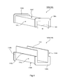
- FIG. 4 is a schematic view illustrating a modification of the first casing 110A and the second casing 120A illustrated in FIG. 3 .
- a first casing 110B (110) illustrated in FIG. 4 is obtained by additionally providing plate-like flange portions 118A and 118B upright with respect to the outer peripheral surface respectively on one end side and another end side in a longitudinal direction of the first casing 110A illustrated in FIG. 3 .
- a second casing 120B (120) illustrated in FIG. 4 is obtained by additionally providing plate-like flange portions 128A and 128B upright with respect to the outer peripheral surface respectively on one end side and another end side in a longitudinal direction of the second casing 120A illustrated in FIG. 3 .
- the flange portion 104A is formed of the flange portion 118A and the flange portion 128A
- the flange portion 104B is formed of the flange portion 118B and the flange portion 128B.
- first casing 110A and the second casing 120A as exemplified in FIG. 3 which are not provided with the flange portions, are used to form the bobbin 100
- first casing 110A and the second casing 120A are combined with each other to form the quadrangular cylindrical bobbin 100
- ring-shaped plates corresponding to the flange portions 104A and 104B may be fitted respectively to one end side and another end side of the bobbin 100.
- first connecting core portion 40A and the second connecting core portion 42A are not particularly limited as long as being formed of a magnetic body.
- the first connecting core portion 40A and the second connecting core portion 42A may be formed of a laminated body obtained by laminating a plurality of plate-like magnetic bodies.
- FIG. 5 is a schematic sectional view illustrating an example of an arrangement relationship of the laminated core portions 130, the first connecting core portion 40, and the second connecting core portion 42B which form the magnetic component 10A illustrated in FIGS. 1A and 1B .
- FIG. 5 does not illustrate the heat-resistant insulating sheet 150, or any individual one of the wound rows of the conductive wire forming the coil portion 140.
- the laminated core portions 130A and 130B are arranged respectively in the bobbins 100 respectively forming the magnetic units 30A and 30B, and the laminated core portions 130A and 130B are each divided by a gap portion 160 provided at a substantially central portion in the longitudinal direction of the bobbin 100.
- the first connecting core portion 40A is provided between a part of a laminated core portion 130A1 (130A), which is projected from the one end side (direction X1 side) of the bobbin 100, and a part of a laminated core portion 130B1 (130B), which is projected also from the one end side (direction X1 side) of the bobbin 100.
- the second connecting core portion 42A is provided between a part of a laminated core portion 130A2 (130A), which is projected from the another end side (direction X2 side) of the bobbin 100, and a part of a laminated core portion 130B2 (130B), which is projected from the another end side (direction X2 side) of the bobbin 100.
- the laminated core portions 130A, the laminated core portions 130B, the first connecting core portion 40A, and the second connecting core portion 42A are arranged to form an annular core having an annular shape.
- each of the laminated core portions 130A and 130B respectively forming the magnetic units 30A and 30B are projected respectively from the one end and the another end of the bobbin 100.
- the first connecting core portion 40A is provided between the parts on one end side of the laminated core portions 130A and 130B respectively forming the magnetic units 30A and 30B
- the second connecting core portion 42A is provided between the parts another end side of the laminated core portions 130A and 130B respectively forming the magnetic units 30A and 30B.
- each of the gap portions 160 there is arranged a partition plate (not shown in FIG. 5 ) for substantially perfectly partitioning each of the laminated core portions 130A and 130B in the longitudinal direction of the bobbin 100.
- the laminated core portions 130A and 130B positioned in the respective bobbins 100 each include the gap portion 160 provided to divide the longitudinal direction of corresponding one of the bobbins 100 (to divide the laminated core portions 130A and 130B with respect to the longitudinal direction of corresponding one of the bobbins 100), and the partition plate for substantially perfectly partitioning a space on an inner peripheral side of corresponding one of the bobbins 100 in the longitudinal direction of the bobbin 100 is provided at a position corresponding to the gap portion 160 in the bobbin 100.
- This partition plate may be formed in advance, for example, on the inner peripheral surface of at least one of the first casing 110 and the second casing 120, or may be arranged and fixed in the bobbin 100 at the time of assembly of the bobbin 100.
- the laminated core portions 130, the first connecting core portion 40A, and the second connecting core portion 42A are annularly arranged, and the at least one gap portion 160 is provided to partition the annular core including those core portions in a circumferential direction
- the laminated core portions 130, the first connecting core portion 40A, and the second connecting core portion 42A may be arranged in other appropriate combinations than that exemplified in FIG. 5 .
- FIG. 6 is a schematic sectional view illustrating another example of the arrangement relationship of the laminated core portions 130, the first connecting core portion 40, and the second connecting core portion 42. Note that, FIG. 6 does not illustrate the heat-resistant insulating sheet 150, or any individual one of the wound rows of the conductive wire forming the coil portion 140.
- lengths of laminated core portions 130A3 (130A) and 130B3 (130B) are each set to be substantially equal to a length of the bobbin 100.
- a first connecting core portion 40B (40) and a second connecting core portion 42B (42) have a shape vertically longer than that of the first connecting core portion 40A and the second connecting core portion 42A in the example illustrated in FIG. 5 .
- the gap portions 160 are formed correspondingly to a connection interface between the laminated core portion 130A3 and the first connecting core portion 40B, a connection interface between the laminated core portion 130A3 and the second connecting core portion 42B, a connection interface between the laminated core portion 130B3 and the first connecting core portion 40B, and a connection interface between the laminated core portion 130B3 and the second connecting core portion 42B.
- a laminated body obtained by simply laminating plate-like magnetic bodies having the same planar shape may be utilized as the first connecting core portions 40 and the second connecting core portions 42 exemplified, for example, in FIGS. 5 and 6 .
- a part of the plate-like magnetic bodies 132 forming the laminated core portion 130A and the laminated core portion 130B may be utilized as the first connecting core portions 40 and the second connecting core portions 42.
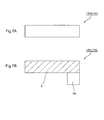
- FIGS. 7A and 7B are plan views each illustrating an example of the plate-like magnetic body 132 which forms the laminated core portion 130.
- a region S indicated by shading in FIG. 7B is a part having the same shape and size as those of a plate-like magnetic body 132S illustrated in FIG. 7A .
- the shape of the plate-like magnetic body 132 for example, the rectangular plate-like magnetic body 132S ( FIG. 7A ), an L-shaped plate-like magnetic body 132L ( FIG. 7B ), and the like may be employed.
- the plate-like magnetic bodies 132 having the same planar shape are laminated in an overlapping manner in a planar direction.
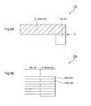
- FIGS. 8A and 8B are schematic views illustrating another example of the laminated core portion 130. Specifically, FIG.
- FIG. 8A is a plan view of a laminated structure 170 obtained by alternately laminating the plate-like magnetic bodies 132S and the plate-like magnetic bodies 132L and including a laminated core portion 130X (130), and FIG. 8B is a side view of the laminated structure 170 illustrated in FIG. 8A (side view viewed from an arrow E direction in FIG. 8A ).
- a part of the plate-like magnetic body 132L, which overlaps the plate-like magnetic body 132S in the region S forms the laminated core portion 130X.
- a region NS of the plate-like magnetic body 132L in which the plate-like magnetic body 132L cannot overlap the plate-like magnetic body 132S in the region S, forms a comb-shaped comb portion 134.
- a part at which those comb portions 134 are fitted to each other can be utilized as at least one of the first connecting core portion 40 and the second connecting core portion 42.
- bonding processing on both the plate-like magnetic bodies 132L may be omitted at the part formed by fitting the comb portions 134 to each other.
- the entire outer surface of the magnetic component body 20 of the magnetic component 10 according to the embodiment of the present invention is covered with the varnish layer.
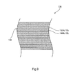
- the magnetic component 10 according to the embodiment of the present invention at a part of the laminated body (laminated core portion 130), which is positioned on an inner peripheral side of the coil portion 140, one surface of one plate-like magnetic body 132A (132) and one surface of another plate-like magnetic body 132B arranged adjacent to the one plate-like magnetic body 132A, which form the laminated body (laminated core portion 130), are held in direct contact with each other over the entire surfaces.
- laminated body 132A a part of the laminated body 132A
- another plate-like magnetic body 132B arranged adjacent to the one plate-like magnetic body 132A, which form the laminated body (laminated core portion 130
- part of the laminated body (laminated core portion 130), which is positioned on the inner peripheral side of the coil portion 140" means a part of the laminated core portion 130, which is positioned in a region CL indicated by the two-way arrow in the example illustrated in FIGS. 5 and 6 . Therefore, in the example illustrated in FIG. 5 , other parts of the laminated core portion 130, which are positioned outside both the ends of the bobbin 100, are excluded from the "part of the laminated body (laminated core portion 130), which is positioned on the inner peripheral side of the coil portion 140." Further, in the example illustrated in FIG.
- the laminated core portion 130 is housed and arranged in the bobbin 100 so as not to protrude from opening portions at both the ends of the bobbin 100. Therefore, in the example illustrated in FIG. 6 , the laminated core portion 130 is substantially entirely positioned on the inner peripheral side of the coil portion 140 except parts provided with the flange portions 104A and 104B.
- the description "in direct contact with each other over the substantially entire surfaces” means a state in which, at the part of the laminated core portion 130 (region CL), which is positioned on the inner peripheral side of the coil portion 140, the one plate-like magnetic body 132A and the another plate-like magnetic body 132B are held in direct contact with each other over 70% or more of the entire area of the interface 136.
- a rate of direct contact of those plate-like magnetic bodies 132A and 132B with each other is preferably 80% or more, more preferably 90% or more, most preferably 100% of the entire area of the interface 136.
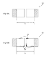
- FIGS. 10A and 10B are schematic plan views each illustrating an example of the interface 136 between any two plate-like magnetic bodies 132 of the plurality of plate-like magnetic bodies 132, which form the laminated core portion 130A illustrated in FIG. 5 .
- at least one of hollow parts and solid parts indicates the part positioned on the inner peripheral side of the coil portion 140 (region CL), and shaded parts indicate parts out of the inner peripheral side of the coil portion 140.
- the hollow parts indicate parts at which the surface of the one plate-like magnetic body 132A and the surface of the another plate-like magnetic body 132B are held in direct contact with each other, and the solid parts indicate parts at which varnish 138 exists.
- the adhesive agent and the varnish 138 may be perfectly eliminated over the entire interface 136 within the region CL.
- the varnish 138 may slightly exist at some parts of the interface 136 within the region CL. Further, as exemplified in FIG.
- the varnish 138 existing in regions near end portions of the interface 136 within the region CL is not arranged at the time of assembly of the laminated core portion 130, but is derived from varnish that has somewhat intruded from the end portion side of the interface 136 into the interface 136 at the time when the varnish is applied through immersion treatment or the like with respect to the entire outer surface of the assembled magnetic component body 20.
- the magnetic component 10 may further include cover members for covering those parts.
- FIG. 11 is a perspective view illustrating another example of the magnetic component 10 according to the embodiment of the present invention
- FIG. 12 is a perspective view illustrating an example of a cover member used for the magnetic component 10 according to the embodiment of the present invention, which is illustrated in FIG. 11
- a magnetic component 10B (10) illustrated in FIG. 11 is obtained by further providing two cover members 50A (50) and 50B (50) to the magnetic component 10A illustrated in FIGS. 1A and 1B .
- the cover member 50 has a bottomed quadrangular cylindrical shape.
- the cover member 50 When the part of the laminated core portion 130A and the first connecting core portion 40A which are positioned outside the region between the two flange portions 104A and 104B (or part of the laminated core portion 130B and the second connecting core portion 42A which are positioned outside the region between the two flange portions 104A and 104B) are inserted into an opening portion 52 of the cover member 50, the cover member 50 substantially entirely covers the part of the laminated core portion 130A and the first connecting core portion 40A which are positioned outside the region between the two flange portions 104A and 104B (or part of the laminated core portion 130B and the second connecting core portion 42A which are positioned outside the region between the two flange portions 104A and 104B).
- the cover member 50 include fixation portions 54 as appropriate for ease of fixation of the magnetic component 10B with respect, for example, to various devices and members.
- the magnetic component 10 according to the embodiment of the present invention is prepared by the following procedure. Specifically, first, at least two magnetic units 30 are prepared through a laminated body arranging step, a coil portion forming step, and a coil portion covering step.
- the magnetic component body 20 is prepared through a connecting core portion forming step of arranging the magnetic units 30 parallel to each other, forming the first connecting core portion 40 for connecting the ends on one side (direction X1 side) of the laminated core portions 130 of the magnetic units 30 respectively to each other, and forming the second connecting core portion 42 for connecting the ends on another side (direction X2 side) of the laminated core portions 130 of the magnetic units 30 respectively to each other.
- the magnetic component 10 according to the embodiment of the present invention is obtained further through a varnish layer forming step of forming the varnish layer by applying varnish to the outer surface of the magnetic component body 20.
- the laminated body arranging step at least a laminated body obtained by laminating the plurality of plate-like magnetic bodies 132 in a manner that the surfaces of those plate-like magnetic bodies 132 are held in direct contact with each other is arranged in the quadrangular cylindrical bobbin 100.
- the plate-like magnetic bodies 132 are not bonded to each other with use of an adhesive component which may cause solid matters to remain finally in the interface 136, such as an adhesive agent. Therefore, at the time of manufacturing the magnetic component 10 according to the embodiment of the present invention, a bonding step of bonding the plate-like magnetic bodies 132 forming the laminated core portion 130 to each other can be omitted.
- the laminated body (to be formed as the laminated core portion 130) may be arranged in a manner that a part of the laminated body is projected from the one end side of the bobbin 100.
- the laminated body (to be formed as the laminated core portion 130) may be arranged in the bobbin 100 in a manner that, substantially as in FIG. 5 , both ends of the laminated body are projected from both the end sides of the bobbin 100.
- the laminated body (to be formed as the laminated core portion 130) may be arranged in a manner that the laminated body is housed in the bobbin 100.
- the laminated body is arranged after the partition plate is arranged in advance in the bobbin 100 or the component of the bobbin prior to assembly of the bobbin.
- the laminated body (to be formed as the laminated core portion 130) includes the gap portion 160 provided to divide the longitudinal direction of the bobbin 100.
- the partition plate for substantially perfectly partitioning the space on the inner peripheral side of the bobbin 100 in the longitudinal direction of the bobbin 100 is provided at the position corresponding to the gap portion 160 in the bobbin 100.
- the coil portion forming step is performed.
- the coil portion 140 in order that a pressing force is applied at least in the lamination direction of the laminated body arranged within the bobbin 100, the coil portion 140 is formed on the outer peripheral surface 102 of the bobbin 100 by winding a conductive wire around the outer peripheral surface 102 of the bobbin 100. How to wind the conductive wire is not particularly limited, and, for example, regular winding may be employed.
- the coil portion 140 may be formed in any region in the longitudinal direction of the bobbin 100.
- the coil portion 140 is formed to cover substantially the entire outer peripheral surface 102 from the one opening portion side to the another opening portion side of the bobbin 100. Further, as exemplified, for example, in FIGS. 1A and 1B , when the bobbin 100 includes the pair of flange portions 104A and 104B for restricting a position of the coil portion 140, the coil portion 140 is formed to cover the entire outer peripheral surface 102 between the flange portion 104A and the flange portion 104B.
- the laminated body (laminated core portion 130) is at least pressed in the lamination direction through intermediation of the bobbin 100, and hence the plate-like magnetic bodies 132 existing in the region CL inside the coil portion 140 are held firmly in contact with each other. Therefore, after the magnetic component 10 is completed, the individual ones of plate-like magnetic bodies 132 forming the laminated core portion 130 are not separated from each other. Also for this reason, the bonding step of bonding the plate-like magnetic bodies 132 forming the laminated core portion 130 to each other can be omitted.
- the laminated body (laminated core portion 130) is held in press-contact with the inner peripheral surface of the bobbin 100 on at least both surfaces in the lamination direction (for example, the top surface 130TP and the bottom surface 130BTM illustrated in FIG. 2 ).
- the laminated core portion 130 and the bobbin 100 can be suppressed.
- the magnetic component 10 according to the embodiment of the present invention can be downsized further and more easily.
- varnish in a molten state is much less liable to intrude into the interface 136 positioned in the region CL inside the coil portion 140 in the laminated core portion 130. Therefore, in the interface 136 positioned within the region CL inside the coil portion 140 in the laminated core portion 130, as exemplified in FIGS. 10A and 10B , it is also possible to maintain the state in which substantially the entire surfaces of the plate-like magnetic bodies 132 are held in direct contact with each other.
- a high fastening force (pressing force) of the wound conductive wire is applied to the laminated body (laminated core portion 130).
- This pressing force is indirectly transmitted through intermediation of the bobbin 100.
- the conductive wire and the laminated body are held in "linear contact” with each other, and hence the pressing force significantly and locally increases. Therefore, the conductive wire is liable to bite into the laminated body, with the result that it is difficult to prevent deformation of the plate-like magnetic bodies 132 forming the laminated body.
- the magnetic component 10 at the time of manufacture, such a pressing force is indirectly transmitted to the laminated body through intermediation of the bobbin 100.
- the bobbin 100 and the laminated body are held in "surface contact" with each other.
- the pressing force is not transmitted in a significantly and locally biased state to the laminated body.
- deformation of the plate-like magnetic bodies 132 forming the laminated body is significantly easily suppressed. Therefore, plate-like magnetic bodies 132 reduced in thickness can be employed, and hence losses caused by generation of eddy current can be suppressed.
- higher efficiency and energy saving in a case where the magnetic component 10 according to the embodiment of the present invention is used in a high-frequency range are easily achieved.
- the outer peripheral surface of the coil portion 140 is covered with the heat-resistant insulating sheet 150.
- heat-resistant insulating paper is used as the heat-resistant insulating sheet 150.
- the present invention is not limited thereto, and there may be appropriately utilized publicly known sheet-like members having heat resistance and insulating properties (such as heat-resistant resin film).
- the magnetic unit 30 is obtained through the laminated body arranging step, the coil portion forming step, and the coil portion covering step. At least two magnetic units 30 are prepared in this way at the time of preparation of one magnetic component 10. However, normally, two magnetic units 30 are prepared.
- the connecting core portion forming step is performed.
- the magnetic units 30 are arranged parallel to each other, and the first connecting core portion 40 for connecting the ends on one side (direction X1 side) of the laminated core portions 130 respectively to each other is formed, and the second connecting core portion 42 for connecting the ends on another side (direction X2 side) of the laminated core portions 130 respectively to each other is formed, the laminated core portions 130 respectively forming the magnetic units 30 and each being formed of the laminated body described above.
- the connecting core portion forming step is performed using the two magnetic units 30, the magnetic component body 20 as exemplified in FIGS.
- 1A and 1B is obtained, which includes at least the two magnetic units 30 and the two connecting core portions 40 and 42 in total for connecting the ends on one side (direction X1 side) of the laminated core portions 130 of the two magnetic units 30 respectively to each other and the ends on another side (direction X2 side) of the laminated core portions 130 of the two magnetic units 30 respectively to each other.
- N-1 annular cores each having an annular shape and formed of the laminated core portions 130 and the connecting core portions 40 and 42 as exemplified in FIGS. 5 and 6 .
- the varnish layer forming step of forming the varnish layer by applying varnish to the outer surface of the magnetic component body 20 is performed.
- the varnish layer forming step the magnetic component 10 according to the embodiment of the present invention is obtained.
- steps other than the steps (1) to (5) described above may be appropriately performed when necessary.
- a step of fixing the cover member 50 may be performed after the connecting core portion forming step or the varnish layer forming step.
- the cover members 50 may be fixed in a press-fitting manner, may be bonded with an adhesive agent such as an epoxy-based adhesive agent, or may be fixed by combination of the press-fitting manner and the adhesive agent.
- an adhesive agent such as an epoxy-based adhesive agent
- 1A and 1B is obtained by performing the varnish layer forming step with respect to the magnetic component body 20.
- the magnetic component 10A and the magnetic component body 20 have the same structure except whether to perform the varnish treatment.
- a half-finished product that has not yet been subjected to the varnish layer forming step corresponds to the magnetic component body 20.
- a half-finished product to which the cover members 50 have been fixed corresponds to the magnetic component body 20.
- the bobbin 100 may be formed of one component, two components as exemplified, for example, in FIG. 3 , or at least three components.
- the bobbin 100 is shaped not with a sheet-like member (for example, insulating member which is soft and easily deformable, such as silicone rubber and paper) which is soft and easily deformable to an extent that the sheet-like member can be rolled around an outer periphery of a laminated core portion as exemplified in Japanese Patent Application Laid-open No.
- the quadrangular cylindrical part of the bobbin 100 is formed of a hard resin having a thickness of from approximately 1 mm to 5 mm.
- examples of resins that can be utilized as such hard resins include a phenol-formaldehyde (PF) resin, a diallyl phthalate (DAP) resin, a polypropylene (PP) resin, a polyvinyl chloride (PVC) resin, a polystyrene (PS) resin, an acrylonitrile butadiene styrene (ABS) resin, and a liquid crystal polymer (LCP) resin.
- PF phenol-formaldehyde
- DAP diallyl phthalate
- PP polypropylene
- PVC polyvinyl chloride
- PS polystyrene
- ABS acrylonitrile butadiene styrene
- LCP liquid crystal polymer
- shapes, sizes, dimensions, and raw materials of components of the bobbin 100 are appropriately selected in accordance with shapes, sizes, and dimensions of the laminated core portion 130 including a laminated body obtained by laminating the plurality of plate-like magnetic bodies 132 so that the laminated body has a quadrangular shape in cross-section. Specifically, those properties are appropriately selected so that the laminated body can be housed in the bobbin 100 and held in press-contact with the inner peripheral surface of the bobbin 100 on at least both the top surface 130TP side and the bottom surface 130BTM side in the lamination direction of the laminated core portion 130 when the conductive wire is wound around the outer peripheral surface 102.
- the bobbin 100 can be formed also by arranging four rectangular plate-like members having substantially the same sizes as those of four surfaces except both end surfaces in the direction of the two-way arrow X of the laminated core portion 130 in a manner that the four rectangular plate-like members are held in close contact respectively with the four surfaces.
- the bobbin 100 be normally formed of at least two components of the first casing 110 and the second casing 120 as exemplified in FIGS. 3 and 4 .
- shapes other than those exemplified in FIGS. 3 and 4 may be appropriately employed as the shape of the first casing 110 as long as one outer peripheral surface of the four outer peripheral surfaces of the quadrangular cylindrical body is formed to be the opening portion 112. Further, shapes other than those exemplified in FIGS. 3 and 4 may be appropriately employed as the shape of the second casing 120 as long as the second casing 120 can be arranged to at least close the opening portion 112 of the first casing 110.
- FIG. 13 is a schematic view illustrating another example of the first casing 110 and the second casing 120 which form the bobbin 100.
- a first casing 110C (110) illustrated in FIG. 13 has substantially the same structure as that of the first casing 110A illustrated in FIG. 3 except that the step portions 116R and 116L are not provided on the outer peripheral surfaces of the side surface portions 114R and 114L.
- a second casing 120C (120) illustrated in FIG. 13 includes a rectangular plate-like member having substantially the same size and shape as those of the opening portion 112. Note that, the flange portions as exemplified in FIG. 4 and the partition plates for forming the gap portions 160 may be fixed also to at least one of the first casing 110C and the second casing 120C illustrated in FIG. 13 .
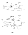
- FIG. 14 is a schematic view illustrating still another example of the first casing 110 and the second casing 120 which form the bobbin 100.
- FIG. 14 illustrates a modification of the first casing 110B and the second casing 120B illustrated in FIG. 4 .
- a first casing 110D (110) illustrated in FIG. 14 has basically the same structure as that of the first casing 110B illustrated in FIG. 4 , and has a feature in that the side surface portion 114R and the bottom surface portion 114B are provided to project to the outside of an interval between the flange portion 118A and the flange portion 118B.
- a second casing 120D (120) illustrated in FIG. 14 has basically the same structure as that of the second casing 120B illustrated in FIG. 4 , and has a feature in that the top surface portion 124T is provided to project to the outside of an interval between the flange portion 128A and the flange portion 128B.
- the first casing 110D and the second casing 120D illustrated in FIG. 14 be used for the bobbin 100.
- the projecting parts (projecting portions 114RP and 114BP) of the side surface portion 114R and the bottom surface portion 114B, which are projected with respect to the flange portions 118A and 118B, and the projecting parts (projecting portions 124TP) of the top surface portion 124T, which are projected with respect to the flange portions 128A and 128B, can cover and support surfaces except the end surfaces in the direction of the two-way arrow X and surfaces (or parts) adjacent to the connecting core portions 40 and 42 of the projecting parts of the laminated core portion 130, which are projected from the opening portions at both the ends of the bobbin 100. Further, as exemplified in FIG.
- first connecting core portion 40B and the second connecting core portion 42B are arranged to respectively close the opening portions at both the ends of the bobbin 100
- first casing 110D and the second casing 120D illustrated in FIG. 14 be used for the bobbin 100.
- projecting portions 114RP, 114BP, 124TP, and 124RP can cover and support both end sides of the first connecting core portion 40B and the second connecting core portion 42B.
- the plate-like magnetic bodies 132 forming the laminated core portion 130 are not particularly limited in thickness. However, when the magnetic component 10 is utilized in use of being activated with high frequency, the thickness is preferred to fall within a range of from 30 ⁇ m to 350 ⁇ m, and more preferred to fall within a range of from 30 ⁇ m to 150 ⁇ m. When the thickness of the plate-like magnetic bodies 132 is set to fall within the above-mentioned ranges, the magnetic component 10 can be easily utilized in use with high frequency while preventing deformation of the plate-like magnetic bodies 132 at the time of manufacture of the magnetic component 10, in particular, at the time of performing the coil portion forming step.
- any material appropriately selected from publicly known materials that can be used as a core member can be utilized as a material for the plate-like magnetic bodies 132.
- the same thicknesses and materials as those of the plate-like magnetic bodies 132 be employed as those of the plate-like magnetic bodies forming the first connecting core portion 40 and the second connecting core portion 42.
- the magnetic component 10 according to the embodiment of the present invention is desired to be used in an inverter and a converter for automobile devices, medical devices, industrial devices, domestic power generators, solar photovoltaic power generators, and the like, and the inverter and the converter are each rated preferably at less than 50 kW, more preferably at 15 kW or less.
Landscapes
- Engineering & Computer Science (AREA)
- Power Engineering (AREA)
- Insulating Of Coils (AREA)
- Coils Or Transformers For Communication (AREA)
- Manufacturing Cores, Coils, And Magnets (AREA)
Abstract
Description
- The present invention relates to a magnetic component and a manufacturing method for the magnetic component.
- In an example of a typical basic structure of a reactor, a main part includes a core formed into an oblong shape by appropriately combining with each other at least two laminated core portions each formed of a laminated body obtained by laminating a plurality of plate-like magnetic bodies, and a pair of cylindrical members (bobbins) surrounding the laminated core portions forming the core while being arranged parallel to each other (for example, refer to Japanese Utility Model Registration No.
3119580 FIG. 4 and others), Japanese Patent Application Laid-open No.2006-351662 FIG. 6 , paragraph [0013], and others), and Japanese Patent Application Laid-open No.2006-13294 FIGS. 1 to 5 , and paragraphs [0007] to [0011], [0022], and others)). - Meanwhile, there has been proposed a reactor in which a conductive wire is directly wound around a laminated core portion through intermediation of a sheet-like insulator without use of the bobbin for the purpose of reducing the number of materials, man-hours, and the like (Japanese Patent Application Laid-open No.
2006-13294 2006-13294 - In order to utilize the reactor structured as described above, for example, in use of being activated with high frequency while suppressing losses through suppression of eddy current to be generated in the plate-like magnetic bodies, it is desired to use extremely thin plate-like magnetic bodies having a thickness of from approximately 30 µm to 150 µm (such as silicon steel plate). However, in such a case, the plate-like magnetic bodies are deformed by a fastening force of the wound conductive wire. As a result, designed performance of the reactor cannot be obtained.
- The present invention has been made in view of the above-mentioned circumstances, and it is therefore an object of the present invention to provide a magnetic component and a manufacturing method for the magnetic component, in which, at a time of manufacture of a magnetic component, a bonding step of bonding plate-like magnetic bodies forming a laminated core portion to each other can be omitted and the plate-like magnetic bodies can be less deformed by a fastening force of a wound conductive wire.
- The above-mentioned object is achieved by the present invention described below.
That is, according to an exemplary embodiment of the present invention, there is provided a magnetic component (10), including a magnetic component body (20) including at least: at least two magnetic units (30) each including: a bobbin (100) having a quadrangular cylindrical shape; a laminated core portion (130) arranged at least in the bobbin (100) and including a laminated body obtained by laminating a plurality of plate-like magnetic bodies (132); a coil portion (140) including a conductive wire wound around an outer peripheral surface (102) of the bobbin (100); and a heat-resistant insulating sheet (150) covering an outer peripheral surface of the coil portion (140); a first connecting core portion (40) including a magnetic body and connecting to each other ends on one side of the laminated core portions (130) respectively forming the at least two magnetic units (30) arranged parallel to each other; and a second connecting core portion (42) including a magnetic body and connecting to each other ends on another side of the laminated core portions (130) respectively forming the at least two magnetic units (30) arranged parallel to each other, in which an outer surface of the magnetic component body (20) is entirely covered with a varnish layer, and in which, in each of the at least two magnetic units (30), one surface of one plate-like magnetic body (132A) and one surface of another plate-like magnetic body (132B) arranged adjacent to the one plate-like magnetic body (132A) are substantially entirely held in direct contact with each other in a region (CL) of the laminated body, the region (CL) being positioned on an inner peripheral side of the coil portion (140), the one plate-like magnetic body (132A) and the another plate-like magnetic body (132B) forming the laminated body. - In a magnetic component (10) according to another exemplary embodiment of the present invention, it is preferred that a thickness of each of the plurality of plate-like magnetic bodies (132) fall within a range of from 30 µm to 350 µm.
In a magnetic component (10) according to still another exemplary embodiment of the present invention, it is preferred that the ends on the one side of the laminated core portions (130) respectively forming the at least two magnetic units (30) and the ends on the another side of the laminated core portions (130) respectively forming the at least two magnetic units (30) are projected from the bobbin (100), that the first connecting core portion (40) is provided at a part between the ends on the one side of the laminated core portions (130) respectively forming the at least two magnetic units (30), and that the second connecting core portion (42) is provided at a part between the ends on the another side of the laminated core portions (130) respectively forming the at least two magnetic units (30).
In a magnetic component (10) according to yet another exemplary embodiment of the present invention, it is preferred that the laminated core portion (130) positioned in the bobbin (100) include a gap portion (160) provided to divide a longitudinal direction of the bobbin (100), and that a partition plate for substantially perfectly partitioning a space on an inner peripheral side of the bobbin (100) in the longitudinal direction of the bobbin (100) is provided at a position corresponding to the gap portion (160) in the bobbin (100). - In a magnetic component (10) according to yet another exemplary embodiment of the present invention, it is preferred that a material for the each of the plurality of plate-like magnetic bodies (132) be silicon steel.
- According to an exemplary embodiment of the present invention, there is provided a manufacturing method for a magnetic component (10), including: a laminated body arranging step of arranging, in a bobbin (100) having a quadrangular cylindrical shape, at least a laminated body obtained by laminating a plurality of plate-like magnetic bodies (132) in a manner that surfaces of the plurality of plate-like magnetic bodies (132) are held in direct contact with each other; a coil portion forming step of forming a coil portion (140) on an outer peripheral surface (102) of the bobbin (100) by winding a conductive wire around the outer peripheral surface (102) of the bobbin (100) so that a pressing force is applied at least in a lamination direction of the laminated body arranged in the bobbin (100); a coil portion covering step of covering an outer peripheral surface of the coil portion (140) with a heat-resistant insulating sheet (150), the laminated body arranging step, the coil portion forming step, and the coil portion covering step being performed to prepare at least two magnetic units (30); a connecting core portion forming step of: arranging the at least two magnetic units (30) parallel to each other; forming a first connecting core portion (40) for connecting to each other ends on one side of laminated core portions (130) respectively forming the at least two magnetic units (30) and each including the laminated body; and forming a second connecting core portion (42) for connecting to each other ends on another side of the laminated core portions (130) respectively forming the at least two magnetic units (30) and each including the laminated body, the connecting core portion forming step being performed to prepare a magnetic component body (20); and a varnish layer forming step of forming a varnish layer by applying varnish to an outer surface of the magnetic component body (20), the varnish layer forming step being performed to obtain the magnetic component (10).
- In a manufacturing method for a magnetic component (10) according to another exemplary embodiment of the present invention, it is preferred that the laminated body arranging step include arranging the laminated body in the bobbin (100) in a manner that both ends of the laminated body are projected from both end sides of the bobbin (100).
In a manufacturing method for a magnetic component (10) according to still another exemplary embodiment of the present invention, it is preferred that the laminated body include a gap portion (160) provided to divide a longitudinal direction of the bobbin (100), and that a partition plate for substantially perfectly partitioning a space on an inner peripheral side of the bobbin (100) in the longitudinal direction of the bobbin (100) is provided at a position corresponding to the gap portion (160) in the bobbin (100).
In a manufacturing method for a magnetic component (10) according to yet another exemplary embodiment of the present invention, it is preferred that a thickness of each of the plurality of plate-like magnetic bodies (132) fall within a range of from 30 µm to 350 µm. - In a manufacturing method for a magnetic component (10) according to yet another exemplary embodiment of the present invention, it is preferred that the each of the plurality of plate-like magnetic bodies (132) is a silicon steel plate.
- According to the present invention, it is possible to provide the magnetic component and the manufacturing method for the magnetic component, in which, at a time of manufacture of the magnetic component, the bonding step of bonding the plate-like magnetic bodies forming the laminated core portion to each other can be omitted and the plate-like magnetic bodies can be less deformed by the fastening force of the wound conductive wire.
-
-
FIGS. 1A and 1B are schematic views of an external appearance of a magnetic component according to an embodiment of the present invention. Specifically,FIG. 1A is a perspective view, andFIG. 1B is a top view. -
FIG. 2 is a sectional end view taken along the line A-A ofFIG. 1B , for illustrating an example of a sectional structure of a magnetic unit which forms a main part of a magnetic component body illustrated inFIGS. 1A and 1B . -
FIG. 3 is a schematic view illustrating an example of a first casing and a second casing which form a bobbin of the magnetic unit illustrated inFIG. 2 . -
FIG. 4 is a schematic view illustrating a modification of the first casing and the second casing illustrated inFIG. 3 . -
FIG. 5 is a schematic sectional view illustrating an example of an arrangement relationship of laminated core portions, a first connecting core portion, and a second connecting core portion which form the magnetic component according to the embodiment of the present invention illustrated inFIGS. 1A and 1B . -
FIG. 6 is a schematic sectional view illustrating another example of the arrangement relationship of the laminated core portions, the first connecting core portion, and the second connecting core portion which form the magnetic component according to the embodiment of the present invention. -
FIGS. 7A and 7B are plan views each illustrating an example of a plate-like magnetic body which forms the laminated core portion. Specifically,FIG. 7A illustrates a rectangular plate-like magnetic body, andFIG. 7B illustrates an L-shaped plate-like magnetic body. -
FIGS. 8A and 8B are schematic views illustrating another example of the laminated core portion. Specifically,FIG. 8A is a plan view of a laminated structure obtained by alternately laminating the rectangular plate-like magnetic bodies illustrated inFIG. 7A and the L-shaped plate-like magnetic bodies illustrated inFIG. 7B and including the laminated core portion, andFIG. 8B is a side view of the laminated structure illustrated inFIG. 8A (side view viewed from an arrow E direction inFIG. 8A ). -
FIG. 9 is a sectional view illustrating an example of a sectional structure of the laminated core portion. -
FIGS. 10A and 10B are schematic views each illustrating an example of an interface between the plate-like magnetic bodies which form the laminated core portions illustrated inFIG. 5 . Specifically,FIG. 10A illustrates a state in which the plate-like magnetic bodies are held in direct contact with each other over the entire interface within a region CL inside a coil portion, andFIG. 10B illustrates a state in which varnish slightly exists in a part of the interface within the region CL inside the coil portion. -
FIG. 11 is a perspective view illustrating another example of the magnetic component according to the embodiment of the present invention. -
FIG. 12 is a perspective view illustrating an example of a cover member used for the magnetic component according to the embodiment of the present invention, which is illustrated inFIG. 11 . -
FIG. 13 is a schematic view illustrating another example of the first casing and the second casing which form the bobbin. -
FIG. 14 is a schematic view illustrating still another example of the first casing and the second casing which form the bobbin. -
FIGS. 1A and 1B are schematic views of an external appearance of amagnetic component 10A (10) according to an embodiment of the present invention. Specifically,FIG. 1A is a perspective view, andFIG. 1B is a top view. Further,FIG. 2 is an end view illustrating an example of a sectional structure of amagnetic unit 30 which forms a main part of amagnetic component body 20 illustrated inFIGS. 1A and 1B , specifically, illustrating a sectional structure across a segment between reference symbols A-A inFIG. 1B . Still further,FIG. 3 is a schematic view illustrating an example of afirst casing 110 and asecond casing 120 which form abobbin 100 of themagnetic unit 30 illustrated inFIG. 2 . Note that,FIGS. 1A and 1B do not illustrate any individual one of plate-likemagnetic bodies 132 which form alaminated core portion 130 and a first connectingcore portion 40A (40). Further, a two-way arrow X illustrated inFIGS. 1A and 1B and other figures represents a direction parallel to a central axis direction of thebobbin 100. - The
magnetic component 10A illustrated inFIGS. 1A and 1B includes themagnetic component body 20 and a varnish layer (not shown) covering an entire outer surface of themagnetic component body 20. Themagnetic component body 20 includes two magnetic units 30 (30A and 30B) arranged parallel to each other. One end side (direction X1 side inFIGS. 1A and 1B ) of alaminated core portion 130A (130) which forms themagnetic unit 30A and one end side (direction X1 side) of alaminated core portion 130B (130) which forms themagnetic unit 30B are connected to each other with the first connectingcore portion 40A (40), and another end side (direction X2 side inFIGS. 1A and 1B ) of thelaminated core portion 130A and another end side (direction X2 side) of thelaminated core portion 130B are connected to each other with a second connectingcore portion 42A (42). Note that, the one end side/direction X1 side (or the another end side/direction X2 side) of thelaminated core portion 130 includes an end surface substantially orthogonal to an X-axis and a region near the end surface of four side surfaces of thelaminated core portion 130. - Further, as illustrated in
FIG. 2 , themagnetic unit 30 includes at least the following: thebobbin 100 including afirst casing 110A (110) and asecond casing 120A (120) and having a quadrangular cylindrical shape and both ends provided with opening portions (not shown inFIG. 2 ); thelaminated core portion 130 arranged in thebobbin 100; acoil portion 140 including a conductive wire wound around an outerperipheral surface 102 of thebobbin 100; and a heat-resistantinsulating sheet 150 covering an outer peripheral surface of thecoil portion 140. Here, thelaminated core portion 130 includes a laminated body obtained by laminating a plurality of plate-likemagnetic bodies 132. In both surfaces in a lamination direction of thelaminated core portion 130, a top surface 130TP is held in contact with an inner peripheral surface of thesecond casing 120A, and a bottom surface 130BTM is held in contact with an inner peripheral surface of thefirst casing 110A. Note that,FIG. 2 does not illustrate any individual one of wound rows of the conductive wire forming thecoil portion 140. - Further, as illustrated in
FIGS. 1A and 1B , it is preferred that, on one end side (direction X1 side) and another end side (direction X2 side) of the outerperipheral surface 102 of thebobbin 100,flange portions - The
first casing 110A forming thebobbin 100 has a shape in which one outer peripheral surface of four outer peripheral surfaces of a quadrangular cylindrical body is formed to be an openingportion 112. Further, thesecond casing 120A is arranged to close at least theopening portion 112 of thefirst casing 110A. In the example illustrated inFIGS. 2 and3 , thefirst casing 110A includes aside surface portion 114R and aside surface portion 114L as two outer peripheral surfaces positioned on both horizontal sides of theopening portion 112, and abottom surface portion 114B as one outer peripheral surface facing theopening portion 112. On outer peripheral surfaces of theside surface portions step portions opening portion 112 side are recessed inward with respect to parts on thebottom surface portion 114B side. In other words, theside surface portions opening portion 112 side than on thebottom surface portion 114B side. - Further, in the example illustrated in
FIGS. 2 and3 , thesecond casing 120A also has a shape in which one outer peripheral surface of four outer peripheral surfaces of a quadrangular cylindrical body is formed to be an openingportion 122. Thesecond casing 120A includes aside surface portion 124R and aside surface portion 124L as two outer peripheral surfaces positioned on both horizontal sides of theopening portion 122, and atop surface portion 124T as one outer peripheral surface facing theopening portion 122. A width W of theopening portion 122 is set to be substantially equal to or somewhat larger than a shortest distance between the outer peripheral surface on theopening portion 112 side of theside surface portion 114R and the outer peripheral surface on theopening portion 112 side of theside surface portion 114L of thefirst casing 110A. Thus, in order to form thebobbin 100 as illustrated inFIG. 2 , thesecond casing 120A is arranged to close at least theopening portion 112 of thefirst casing 110A. - Note that, when the
first casing 110A and thesecond casing 120A are assembled into thebobbin 100 as illustrated inFIGS. 1A and 1B , members serving as theflange portions peripheral surface 102 in a longitudinal direction of thebobbin 100. -
FIG. 4 is a schematic view illustrating a modification of thefirst casing 110A and thesecond casing 120A illustrated inFIG. 3 . Here, afirst casing 110B (110) illustrated inFIG. 4 is obtained by additionally providing plate-like flange portions first casing 110A illustrated inFIG. 3 . Further, asecond casing 120B (120) illustrated inFIG. 4 is obtained by additionally providing plate-like flange portions second casing 120A illustrated inFIG. 3 . When thefirst casing 110B and thesecond casing 120B are combined with each other to form thebobbin 100, theflange portion 104A is formed of theflange portion 118A and theflange portion 128A, and theflange portion 104B is formed of theflange portion 118B and theflange portion 128B. - Note that, when the
first casing 110A and thesecond casing 120A as exemplified inFIG. 3 , which are not provided with the flange portions, are used to form thebobbin 100, after thefirst casing 110A and thesecond casing 120A are combined with each other to form the quadrangularcylindrical bobbin 100, for example, ring-shaped plates corresponding to theflange portions bobbin 100. - Further, ends on one side (direction X1 side) of the
laminated core portions 130 respectively forming themagnetic units core portion 40A formed of a magnetic body, and ends on another side (direction X2 side) of thelaminated core portions 130 respectively forming themagnetic units core portion 42A formed of a magnetic body. The first connectingcore portion 40A and the second connectingcore portion 42A are not particularly limited as long as being formed of a magnetic body. For example, similarly to thelaminated core portion 130, the first connectingcore portion 40A and the second connectingcore portion 42A may be formed of a laminated body obtained by laminating a plurality of plate-like magnetic bodies. -
FIG. 5 is a schematic sectional view illustrating an example of an arrangement relationship of thelaminated core portions 130, the first connectingcore portion 40, and the second connectingcore portion 42B which form themagnetic component 10A illustrated inFIGS. 1A and 1B .FIG. 5 does not illustrate the heat-resistantinsulating sheet 150, or any individual one of the wound rows of the conductive wire forming thecoil portion 140. - As illustrated in
FIG. 5 , thelaminated core portions bobbins 100 respectively forming themagnetic units laminated core portions gap portion 160 provided at a substantially central portion in the longitudinal direction of thebobbin 100. The first connectingcore portion 40A is provided between a part of a laminated core portion 130A1 (130A), which is projected from the one end side (direction X1 side) of thebobbin 100, and a part of a laminated core portion 130B1 (130B), which is projected also from the one end side (direction X1 side) of thebobbin 100. Similarly, the second connectingcore portion 42A is provided between a part of a laminated core portion 130A2 (130A), which is projected from the another end side (direction X2 side) of thebobbin 100, and a part of a laminated core portion 130B2 (130B), which is projected from the another end side (direction X2 side) of thebobbin 100. In other words, thelaminated core portions 130A, thelaminated core portions 130B, the first connectingcore portion 40A, and the second connectingcore portion 42A are arranged to form an annular core having an annular shape. In still other words, the one end side and the another end side of each of thelaminated core portions magnetic units bobbin 100. In addition, the first connectingcore portion 40A is provided between the parts on one end side of thelaminated core portions magnetic units core portion 42A is provided between the parts another end side of thelaminated core portions magnetic units - Note that, in the example illustrated in
FIG. 5 , in each of thegap portions 160, there is arranged a partition plate (not shown inFIG. 5 ) for substantially perfectly partitioning each of thelaminated core portions bobbin 100. In other words, thelaminated core portions respective bobbins 100 each include thegap portion 160 provided to divide the longitudinal direction of corresponding one of the bobbins 100 (to divide thelaminated core portions bobbins 100 in the longitudinal direction of thebobbin 100 is provided at a position corresponding to thegap portion 160 in thebobbin 100. This partition plate may be formed in advance, for example, on the inner peripheral surface of at least one of thefirst casing 110 and thesecond casing 120, or may be arranged and fixed in thebobbin 100 at the time of assembly of thebobbin 100. - Further, as long as the
laminated core portions 130, the first connectingcore portion 40A, and the second connectingcore portion 42A are annularly arranged, and the at least onegap portion 160 is provided to partition the annular core including those core portions in a circumferential direction, thelaminated core portions 130, the first connectingcore portion 40A, and the second connectingcore portion 42A may be arranged in other appropriate combinations than that exemplified inFIG. 5 . -
FIG. 6 is a schematic sectional view illustrating another example of the arrangement relationship of thelaminated core portions 130, the first connectingcore portion 40, and the second connectingcore portion 42. Note that,FIG. 6 does not illustrate the heat-resistantinsulating sheet 150, or any individual one of the wound rows of the conductive wire forming thecoil portion 140. In the example illustrated inFIG. 6 , lengths of laminated core portions 130A3 (130A) and 130B3 (130B) are each set to be substantially equal to a length of thebobbin 100. Further, a first connectingcore portion 40B (40) and a second connectingcore portion 42B (42) have a shape vertically longer than that of the first connectingcore portion 40A and the second connectingcore portion 42A in the example illustrated inFIG. 5 . Further, thegap portions 160 are formed correspondingly to a connection interface between the laminated core portion 130A3 and the first connectingcore portion 40B, a connection interface between the laminated core portion 130A3 and the second connectingcore portion 42B, a connection interface between the laminated core portion 130B3 and the first connectingcore portion 40B, and a connection interface between the laminated core portion 130B3 and the second connectingcore portion 42B. - Further, a laminated body obtained by simply laminating plate-like magnetic bodies having the same planar shape may be utilized as the first connecting
core portions 40 and the second connectingcore portions 42 exemplified, for example, inFIGS. 5 and6 . However, a part of the plate-likemagnetic bodies 132 forming thelaminated core portion 130A and thelaminated core portion 130B may be utilized as the first connectingcore portions 40 and the second connectingcore portions 42. -
FIGS. 7A and 7B are plan views each illustrating an example of the plate-likemagnetic body 132 which forms thelaminated core portion 130. Note that, a region S indicated by shading inFIG. 7B is a part having the same shape and size as those of a plate-likemagnetic body 132S illustrated inFIG. 7A . With regard to the shape of the plate-likemagnetic body 132, for example, the rectangular plate-likemagnetic body 132S (FIG. 7A ), an L-shaped plate-likemagnetic body 132L (FIG. 7B ), and the like may be employed. Then, in order to form thelaminated core portion 130, normally, the plate-likemagnetic bodies 132 having the same planar shape are laminated in an overlapping manner in a planar direction. - However, a part of a laminated structure obtained by alternately laminating plate-like
magnetic bodies 132 of two types, which are different from each other in planar shape, may be utilized as thelaminated core portion 130. For example, a part of a laminated structure obtained by alternately laminating the plate-likemagnetic bodies 132S and the plate-likemagnetic bodies 132L in an overlapping manner in the region S may be utilized as thelaminated core portion 130.FIGS. 8A and 8B are schematic views illustrating another example of thelaminated core portion 130. Specifically,FIG. 8A is a plan view of alaminated structure 170 obtained by alternately laminating the plate-likemagnetic bodies 132S and the plate-likemagnetic bodies 132L and including alaminated core portion 130X (130), andFIG. 8B is a side view of thelaminated structure 170 illustrated inFIG. 8A (side view viewed from an arrow E direction inFIG. 8A ). In thelaminated structure 170 illustrated inFIGS. 8A and 8B , a part of the plate-likemagnetic body 132L, which overlaps the plate-likemagnetic body 132S in the region S, forms thelaminated core portion 130X. Meanwhile, a region NS of the plate-likemagnetic body 132L, in which the plate-likemagnetic body 132L cannot overlap the plate-likemagnetic body 132S in the region S, forms a comb-shapedcomb portion 134. Thus, whencomb portions 134 of twolaminated structures 170 are fitted to each other, a part at which thosecomb portions 134 are fitted to each other can be utilized as at least one of the first connectingcore portion 40 and the second connectingcore portion 42. In such a case, bonding processing on both the plate-likemagnetic bodies 132L may be omitted at the part formed by fitting thecomb portions 134 to each other. - Further, the entire outer surface of the
magnetic component body 20 of themagnetic component 10 according to the embodiment of the present invention is covered with the varnish layer. However, in themagnetic component 10 according to the embodiment of the present invention, at a part of the laminated body (laminated core portion 130), which is positioned on an inner peripheral side of thecoil portion 140, one surface of one plate-likemagnetic body 132A (132) and one surface of another plate-likemagnetic body 132B arranged adjacent to the one plate-likemagnetic body 132A, which form the laminated body (laminated core portion 130), are held in direct contact with each other over the entire surfaces. In other words, as exemplified inFIG. 9 , at the part of thelaminated core portion 130, which is positioned on the inner peripheral side of thecoil portion 140, in the lamination direction of thelaminated core portion 130, none of an adhesive agent and even varnish covering the entire outer surface of themagnetic component body 20 substantially exists in aninterface 136 between the one plate-likemagnetic body 132A and the another plate-likemagnetic body 132B adjacent to each other. - The description "part of the laminated body (laminated core portion 130), which is positioned on the inner peripheral side of the
coil portion 140" means a part of thelaminated core portion 130, which is positioned in a region CL indicated by the two-way arrow in the example illustrated inFIGS. 5 and6 . Therefore, in the example illustrated inFIG. 5 , other parts of thelaminated core portion 130, which are positioned outside both the ends of thebobbin 100, are excluded from the "part of the laminated body (laminated core portion 130), which is positioned on the inner peripheral side of thecoil portion 140." Further, in the example illustrated inFIG. 6 , thelaminated core portion 130 is housed and arranged in thebobbin 100 so as not to protrude from opening portions at both the ends of thebobbin 100. Therefore, in the example illustrated inFIG. 6 , thelaminated core portion 130 is substantially entirely positioned on the inner peripheral side of thecoil portion 140 except parts provided with theflange portions - Further, the description "in direct contact with each other over the substantially entire surfaces" means a state in which, at the part of the laminated core portion 130 (region CL), which is positioned on the inner peripheral side of the
coil portion 140, the one plate-likemagnetic body 132A and the another plate-likemagnetic body 132B are held in direct contact with each other over 70% or more of the entire area of theinterface 136. Note that, a rate of direct contact of those plate-likemagnetic bodies interface 136. - In the following, description is made of the features described above in more detail with reference to the drawings.
FIGS. 10A and 10B are schematic plan views each illustrating an example of theinterface 136 between any two plate-likemagnetic bodies 132 of the plurality of plate-likemagnetic bodies 132, which form thelaminated core portion 130A illustrated inFIG. 5 . InFIGS. 10A and 10B , at least one of hollow parts and solid parts indicates the part positioned on the inner peripheral side of the coil portion 140 (region CL), and shaded parts indicate parts out of the inner peripheral side of thecoil portion 140. Further, the hollow parts indicate parts at which the surface of the one plate-likemagnetic body 132A and the surface of the another plate-likemagnetic body 132B are held in direct contact with each other, and the solid parts indicate parts at which varnish 138 exists. As illustrated inFIG. 10A , in themagnetic component 10 according to the embodiment of the present invention, the adhesive agent and thevarnish 138 may be perfectly eliminated over theentire interface 136 within the region CL. However, as illustrated inFIG. 10B , thevarnish 138 may slightly exist at some parts of theinterface 136 within the region CL. Further, as exemplified inFIG. 10B , thevarnish 138 existing in regions near end portions of theinterface 136 within the region CL is not arranged at the time of assembly of thelaminated core portion 130, but is derived from varnish that has somewhat intruded from the end portion side of theinterface 136 into theinterface 136 at the time when the varnish is applied through immersion treatment or the like with respect to the entire outer surface of the assembledmagnetic component body 20. - Note that, in the example illustrated in
FIGS. 1 and5 , on an outside of the region between the twoflange portions bobbin 100, the projecting parts of thelaminated core portions core portion 40A, and the second connectingcore portion 42A exist. In such a case, themagnetic component 10 may further include cover members for covering those parts. -
FIG. 11 is a perspective view illustrating another example of themagnetic component 10 according to the embodiment of the present invention, andFIG. 12 is a perspective view illustrating an example of a cover member used for themagnetic component 10 according to the embodiment of the present invention, which is illustrated inFIG. 11 . Amagnetic component 10B (10) illustrated inFIG. 11 is obtained by further providing twocover members 50A (50) and 50B (50) to themagnetic component 10A illustrated inFIGS. 1A and 1B . - As illustrated in
FIG. 12 , thecover member 50 has a bottomed quadrangular cylindrical shape. When the part of thelaminated core portion 130A and the first connectingcore portion 40A which are positioned outside the region between the twoflange portions laminated core portion 130B and the second connectingcore portion 42A which are positioned outside the region between the twoflange portions portion 52 of thecover member 50, thecover member 50 substantially entirely covers the part of thelaminated core portion 130A and the first connectingcore portion 40A which are positioned outside the region between the twoflange portions laminated core portion 130B and the second connectingcore portion 42A which are positioned outside the region between the twoflange portions FIG. 12 , it is preferred that thecover member 50 includefixation portions 54 as appropriate for ease of fixation of themagnetic component 10B with respect, for example, to various devices and members. - Next, description is made of a manufacturing method for the
magnetic component 10 according to the embodiment of the present invention. Normally, themagnetic component 10 according to the embodiment of the present invention is prepared by the following procedure. Specifically, first, at least twomagnetic units 30 are prepared through a laminated body arranging step, a coil portion forming step, and a coil portion covering step. Next, themagnetic component body 20 is prepared through a connecting core portion forming step of arranging themagnetic units 30 parallel to each other, forming the first connectingcore portion 40 for connecting the ends on one side (direction X1 side) of thelaminated core portions 130 of themagnetic units 30 respectively to each other, and forming the second connectingcore portion 42 for connecting the ends on another side (direction X2 side) of thelaminated core portions 130 of themagnetic units 30 respectively to each other. Lastly, themagnetic component 10 according to the embodiment of the present invention is obtained further through a varnish layer forming step of forming the varnish layer by applying varnish to the outer surface of themagnetic component body 20. In the following, detailed description is made of each of the above-mentioned steps. - In the laminated body arranging step, at least a laminated body obtained by laminating the plurality of plate-like
magnetic bodies 132 in a manner that the surfaces of those plate-likemagnetic bodies 132 are held in direct contact with each other is arranged in the quadrangularcylindrical bobbin 100. In other words, in the laminated body arranging step, at the time of formation or arrangement of the laminated body, the plate-likemagnetic bodies 132 are not bonded to each other with use of an adhesive component which may cause solid matters to remain finally in theinterface 136, such as an adhesive agent. Therefore, at the time of manufacturing themagnetic component 10 according to the embodiment of the present invention, a bonding step of bonding the plate-likemagnetic bodies 132 forming thelaminated core portion 130 to each other can be omitted. - In this laminated body arranging step, as exemplified in
FIG. 5 , the laminated body (to be formed as the laminated core portion 130) may be arranged in a manner that a part of the laminated body is projected from the one end side of thebobbin 100. Alternatively, the laminated body (to be formed as the laminated core portion 130) may be arranged in thebobbin 100 in a manner that, substantially as inFIG. 5 , both ends of the laminated body are projected from both the end sides of thebobbin 100. Still alternatively, as exemplified inFIG. 6 , the laminated body (to be formed as the laminated core portion 130) may be arranged in a manner that the laminated body is housed in thebobbin 100. Further, in the case where thegap portions 160 are provided within thebobbin 100, when the partition plate forming thegap portions 160 is formed separately from the components of the bobbin 100 (for example, at least one of thefirst casing 110 and thesecond casing 120 exemplified inFIG. 3 ), the laminated body is arranged after the partition plate is arranged in advance in thebobbin 100 or the component of the bobbin prior to assembly of the bobbin. Note that, when themagnetic component 10A exemplified inFIG. 5 is prepared, the laminated body (to be formed as the laminated core portion 130) includes thegap portion 160 provided to divide the longitudinal direction of thebobbin 100. Further, the partition plate for substantially perfectly partitioning the space on the inner peripheral side of thebobbin 100 in the longitudinal direction of thebobbin 100 is provided at the position corresponding to thegap portion 160 in thebobbin 100. - After the laminated body arranging step is completed, the coil portion forming step is performed. In this coil portion forming step, in order that a pressing force is applied at least in the lamination direction of the laminated body arranged within the
bobbin 100, thecoil portion 140 is formed on the outerperipheral surface 102 of thebobbin 100 by winding a conductive wire around the outerperipheral surface 102 of thebobbin 100. How to wind the conductive wire is not particularly limited, and, for example, regular winding may be employed. On the outerperipheral surface 102 of thebobbin 100, thecoil portion 140 may be formed in any region in the longitudinal direction of thebobbin 100. However, normally, thecoil portion 140 is formed to cover substantially the entire outerperipheral surface 102 from the one opening portion side to the another opening portion side of thebobbin 100. Further, as exemplified, for example, inFIGS. 1A and 1B , when thebobbin 100 includes the pair offlange portions coil portion 140, thecoil portion 140 is formed to cover the entire outerperipheral surface 102 between theflange portion 104A and theflange portion 104B. - Further, in the coil portion forming step, the laminated body (laminated core portion 130) is at least pressed in the lamination direction through intermediation of the
bobbin 100, and hence the plate-likemagnetic bodies 132 existing in the region CL inside thecoil portion 140 are held firmly in contact with each other. Therefore, after themagnetic component 10 is completed, the individual ones of plate-likemagnetic bodies 132 forming thelaminated core portion 130 are not separated from each other. Also for this reason, the bonding step of bonding the plate-likemagnetic bodies 132 forming thelaminated core portion 130 to each other can be omitted. - In addition, the laminated body (laminated core portion 130) is held in press-contact with the inner peripheral surface of the
bobbin 100 on at least both surfaces in the lamination direction (for example, the top surface 130TP and the bottom surface 130BTM illustrated inFIG. 2 ). Thus, formation of unnecessary spaces between thelaminated core portion 130 and thebobbin 100 can be suppressed. As a result, in comparison with conventional magnetic components including a bobbin in which the laminated core portion obtained by bonding the plate-like magnetic bodies to each other with an adhesive agent is arranged, themagnetic component 10 according to the embodiment of the present invention can be downsized further and more easily. - Still further, in subsequent steps, after the varnish layer forming step is performed, varnish in a molten state is much less liable to intrude into the
interface 136 positioned in the region CL inside thecoil portion 140 in thelaminated core portion 130. Therefore, in theinterface 136 positioned within the region CL inside thecoil portion 140 in thelaminated core portion 130, as exemplified inFIGS. 10A and 10B , it is also possible to maintain the state in which substantially the entire surfaces of the plate-likemagnetic bodies 132 are held in direct contact with each other. - Yet further, in the coil portion forming step, a high fastening force (pressing force) of the wound conductive wire is applied to the laminated body (laminated core portion 130). This pressing force is indirectly transmitted through intermediation of the
bobbin 100. In this context, in a case where the pressing force is transmitted to the laminated body under a state in which the conductive wire and the laminated body are held in direct contact with each other, the conductive wire and the laminated body are held in "linear contact" with each other, and hence the pressing force significantly and locally increases. Therefore, the conductive wire is liable to bite into the laminated body, with the result that it is difficult to prevent deformation of the plate-likemagnetic bodies 132 forming the laminated body. Meanwhile, in themagnetic component 10 according to the embodiment of the present invention, at the time of manufacture, such a pressing force is indirectly transmitted to the laminated body through intermediation of thebobbin 100. In this case, thebobbin 100 and the laminated body are held in "surface contact" with each other. Thus, the pressing force is not transmitted in a significantly and locally biased state to the laminated body. As a result, deformation of the plate-likemagnetic bodies 132 forming the laminated body is significantly easily suppressed. Therefore, plate-likemagnetic bodies 132 reduced in thickness can be employed, and hence losses caused by generation of eddy current can be suppressed. As a result, higher efficiency and energy saving in a case where themagnetic component 10 according to the embodiment of the present invention is used in a high-frequency range are easily achieved. - In the coil portion covering step, the outer peripheral surface of the
coil portion 140 is covered with the heat-resistantinsulating sheet 150. Normally, heat-resistant insulating paper is used as the heat-resistantinsulating sheet 150. However, the present invention is not limited thereto, and there may be appropriately utilized publicly known sheet-like members having heat resistance and insulating properties (such as heat-resistant resin film). - The
magnetic unit 30 is obtained through the laminated body arranging step, the coil portion forming step, and the coil portion covering step. At least twomagnetic units 30 are prepared in this way at the time of preparation of onemagnetic component 10. However, normally, twomagnetic units 30 are prepared. - After the
magnetic units 30 are prepared, the connecting core portion forming step is performed. In this connecting core portion forming step, themagnetic units 30 are arranged parallel to each other, and the first connectingcore portion 40 for connecting the ends on one side (direction X1 side) of thelaminated core portions 130 respectively to each other is formed, and the second connectingcore portion 42 for connecting the ends on another side (direction X2 side) of thelaminated core portions 130 respectively to each other is formed, thelaminated core portions 130 respectively forming themagnetic units 30 and each being formed of the laminated body described above. When the connecting core portion forming step is performed using the twomagnetic units 30, themagnetic component body 20 as exemplified inFIGS. 1A and 1B is obtained, which includes at least the twomagnetic units 30 and the two connectingcore portions laminated core portions 130 of the twomagnetic units 30 respectively to each other and the ends on another side (direction X2 side) of thelaminated core portions 130 of the twomagnetic units 30 respectively to each other. Note that, in a case where at least threemagnetic units 30 are used in this connecting core portion forming step, on a premise that the number of usedmagnetic units 30 is N, there are formed (N-1) annular cores each having an annular shape and formed of thelaminated core portions 130 and the connectingcore portions FIGS. 5 and6 . - Subsequently, the varnish layer forming step of forming the varnish layer by applying varnish to the outer surface of the
magnetic component body 20 is performed. Through this varnish layer forming step, themagnetic component 10 according to the embodiment of the present invention is obtained. Note that, although how to apply varnish is not particularly limited, normally, there may be utilized a method of subjecting themagnetic component body 20 to immersion treatment of immersing themagnetic component body 20 into a tub filled with dissolved varnish. - At the time of the manufacture of the
magnetic component 10 according to the embodiment of the present invention, steps other than the steps (1) to (5) described above may be appropriately performed when necessary. For example, when themagnetic component 10B including thecover members 50 exemplified inFIG. 11 is manufactured, a step of fixing thecover member 50 may be performed after the connecting core portion forming step or the varnish layer forming step. In this case, at the time of fixation of thecover members 50, thecover members 50 may be fixed in a press-fitting manner, may be bonded with an adhesive agent such as an epoxy-based adhesive agent, or may be fixed by combination of the press-fitting manner and the adhesive agent. Note that, themagnetic component 10A illustrated inFIGS. 1A and 1B is obtained by performing the varnish layer forming step with respect to themagnetic component body 20. In other words, themagnetic component 10A and themagnetic component body 20 have the same structure except whether to perform the varnish treatment. Further, in a case where the varnish layer forming step is performed with respect to themagnetic component 10B illustrated inFIG. 11 prior to fixation of thecover members 50, a half-finished product that has not yet been subjected to the varnish layer forming step corresponds to themagnetic component body 20. Meanwhile, in a case where the varnish layer forming step is performed after fixation of thecover members 50, a half-finished product to which thecover members 50 have been fixed corresponds to themagnetic component body 20. - Note that, as long as the
bobbin 100 forming themagnetic component 10 according to the embodiment of the present invention has the quadrangular cylindrical shape, thebobbin 100 may be formed of one component, two components as exemplified, for example, inFIG. 3 , or at least three components. Note that, thebobbin 100 is shaped not with a sheet-like member (for example, insulating member which is soft and easily deformable, such as silicone rubber and paper) which is soft and easily deformable to an extent that the sheet-like member can be rolled around an outer periphery of a laminated core portion as exemplified in Japanese Patent Application Laid-open No.2006-13294 bobbin 100 is formed of a hard resin having a thickness of from approximately 1 mm to 5 mm. Note that, examples of resins that can be utilized as such hard resins include a phenol-formaldehyde (PF) resin, a diallyl phthalate (DAP) resin, a polypropylene (PP) resin, a polyvinyl chloride (PVC) resin, a polystyrene (PS) resin, an acrylonitrile butadiene styrene (ABS) resin, and a liquid crystal polymer (LCP) resin. Otherwise, shapes, sizes, dimensions, and raw materials of components of thebobbin 100 are appropriately selected in accordance with shapes, sizes, and dimensions of thelaminated core portion 130 including a laminated body obtained by laminating the plurality of plate-likemagnetic bodies 132 so that the laminated body has a quadrangular shape in cross-section. Specifically, those properties are appropriately selected so that the laminated body can be housed in thebobbin 100 and held in press-contact with the inner peripheral surface of thebobbin 100 on at least both the top surface 130TP side and the bottom surface 130BTM side in the lamination direction of thelaminated core portion 130 when the conductive wire is wound around the outerperipheral surface 102. - For example, on a premise of the embodiment illustrated in
FIG. 6 , thebobbin 100 can be formed also by arranging four rectangular plate-like members having substantially the same sizes as those of four surfaces except both end surfaces in the direction of the two-way arrow X of thelaminated core portion 130 in a manner that the four rectangular plate-like members are held in close contact respectively with the four surfaces. However, in consideration, for example, of productivity of themagnetic unit 30, it is particularly preferred that thebobbin 100 be normally formed of at least two components of thefirst casing 110 and thesecond casing 120 as exemplified inFIGS. 3 and4 . - In this context, shapes other than those exemplified in
FIGS. 3 and4 may be appropriately employed as the shape of thefirst casing 110 as long as one outer peripheral surface of the four outer peripheral surfaces of the quadrangular cylindrical body is formed to be the openingportion 112. Further, shapes other than those exemplified inFIGS. 3 and4 may be appropriately employed as the shape of thesecond casing 120 as long as thesecond casing 120 can be arranged to at least close theopening portion 112 of thefirst casing 110. -
FIG. 13 is a schematic view illustrating another example of thefirst casing 110 and thesecond casing 120 which form thebobbin 100. Afirst casing 110C (110) illustrated inFIG. 13 has substantially the same structure as that of thefirst casing 110A illustrated inFIG. 3 except that thestep portions side surface portions second casing 120C (120) illustrated inFIG. 13 includes a rectangular plate-like member having substantially the same size and shape as those of theopening portion 112. Note that, the flange portions as exemplified inFIG. 4 and the partition plates for forming thegap portions 160 may be fixed also to at least one of thefirst casing 110C and thesecond casing 120C illustrated inFIG. 13 . -
FIG. 14 is a schematic view illustrating still another example of thefirst casing 110 and thesecond casing 120 which form thebobbin 100. Specifically,FIG. 14 illustrates a modification of thefirst casing 110B and thesecond casing 120B illustrated inFIG. 4 . Afirst casing 110D (110) illustrated inFIG. 14 has basically the same structure as that of thefirst casing 110B illustrated inFIG. 4 , and has a feature in that theside surface portion 114R and thebottom surface portion 114B are provided to project to the outside of an interval between theflange portion 118A and theflange portion 118B. Further, asecond casing 120D (120) illustrated inFIG. 14 has basically the same structure as that of thesecond casing 120B illustrated inFIG. 4 , and has a feature in that thetop surface portion 124T is provided to project to the outside of an interval between theflange portion 128A and theflange portion 128B. - When the parts of the
laminated core portion 130 are projected from the opening portions at both the ends of thebobbin 100 as exemplified inFIGS. 1 and5 , it is preferred that thefirst casing 110D and thesecond casing 120D illustrated inFIG. 14 be used for thebobbin 100. In this case, the projecting parts (projecting portions 114RP and 114BP) of theside surface portion 114R and thebottom surface portion 114B, which are projected with respect to theflange portions top surface portion 124T, which are projected with respect to theflange portions core portions laminated core portion 130, which are projected from the opening portions at both the ends of thebobbin 100. Further, as exemplified inFIG. 6 , also when the first connectingcore portion 40B and the second connectingcore portion 42B are arranged to respectively close the opening portions at both the ends of thebobbin 100, it is preferred that thefirst casing 110D and thesecond casing 120D illustrated inFIG. 14 be used for thebobbin 100. In this case, projecting portions 114RP, 114BP, 124TP, and 124RP can cover and support both end sides of the first connectingcore portion 40B and the second connectingcore portion 42B. - Note that, the plate-like
magnetic bodies 132 forming thelaminated core portion 130 are not particularly limited in thickness. However, when themagnetic component 10 is utilized in use of being activated with high frequency, the thickness is preferred to fall within a range of from 30 µm to 350 µm, and more preferred to fall within a range of from 30 µm to 150 µm. When the thickness of the plate-likemagnetic bodies 132 is set to fall within the above-mentioned ranges, themagnetic component 10 can be easily utilized in use with high frequency while preventing deformation of the plate-likemagnetic bodies 132 at the time of manufacture of themagnetic component 10, in particular, at the time of performing the coil portion forming step. Further, any material appropriately selected from publicly known materials that can be used as a core member can be utilized as a material for the plate-likemagnetic bodies 132. However, it is preferred to utilize silicon steel when themagnetic component 10 is utilized in use of being activated with high frequency. Note that, it is preferred that the same thicknesses and materials as those of the plate-likemagnetic bodies 132 be employed as those of the plate-like magnetic bodies forming the first connectingcore portion 40 and the second connectingcore portion 42. - Note that, the
magnetic component 10 according to the embodiment of the present invention is desired to be used in an inverter and a converter for automobile devices, medical devices, industrial devices, domestic power generators, solar photovoltaic power generators, and the like, and the inverter and the converter are each rated preferably at less than 50 kW, more preferably at 15 kW or less.
Claims (10)
- A magnetic component (10), comprising a magnetic component body (20) comprising at least:at least two magnetic units (30) each comprising:a bobbin (100) having a quadrangular cylindrical shape;a laminated core portion (130) arranged at least in the bobbin (100) and comprising a laminated body obtained by laminating a plurality of plate-like magnetic bodies (132);a coil portion (140) comprising a conductive wire wound around an outer peripheral surface (102) of the bobbin (100); anda heat-resistant insulating sheet (150) covering an outer peripheral surface of the coil portion (140);a first connecting core portion (40) comprising a magnetic body and connecting to each other ends on one side of the laminated core portions (130) respectively forming the at least two magnetic units (30) arranged parallel to each other; anda second connecting core portion (42) comprising a magnetic body and connecting to each other ends on another side of the laminated core portions (130) respectively forming the at least two magnetic units (30) arranged parallel to each other,wherein an outer surface of the magnetic component body (20) is entirely covered with a varnish layer, andwherein, in each of the at least two magnetic units (30), one surface of one plate-like magnetic body (132A) and one surface of another plate-like magnetic body (132B) arranged adjacent to the one plate-like magnetic body (132A) are substantially entirely held in direct contact with each other in a region (CL) of the laminated body, the region(CL) being positioned on an inner peripheral side of the coil portion (140), the one plate-like magnetic body (132A) and the another plate-like magnetic body (132B) forming the laminated body.
- A magnetic component (10) according to claim 1, wherein a thickness of each of the plurality of plate-like magnetic bodies (132) falls within a range of from 30 µm to 350 µm.
- A magnetic component (10) according to claim 1 or 2,
wherein the ends on the one side of the laminated core portions (130) respectively forming the at least two magnetic units (30) and the ends on the another side of the laminated core portions (130) respectively forming the at least two magnetic units (30) are projected from the bobbin (100),
wherein the first connecting core portion (40) is provided at a part between the ends on the one side of the laminated core portions (130) respectively forming the at least two magnetic units (30), and
wherein the second connecting core portion (42) is provided at a part between the ends on the another side of the laminated core portions (130) respectively forming the at least two magnetic units (30). - A magnetic component (10) according to any one of claims 1 to 3,
wherein the laminated core portion (130) positioned in the bobbin (100) comprises a gap portion (160) provided to divide a longitudinal direction of the bobbin (100), and
wherein a partition plate for substantially perfectly partitioning a space on an inner peripheral side of the bobbin (100) in the longitudinal direction of the bobbin (100) is provided at a position corresponding to the gap portion (160) in the bobbin (100). - A magnetic component (10) according to any one of claims 1 to 4, wherein a material for the each of the plurality of plate-like magnetic bodies (132) comprises silicon steel.
- A manufacturing method for a magnetic component (10), comprising:a laminated body arranging step of arranging, in a bobbin (100) having a quadrangular cylindrical shape, at least a laminated body obtained by laminating a plurality of plate-like magnetic bodies (132) in a manner that surfaces of the plurality of plate-like magnetic bodies (132) are held in direct contact with each other;a coil portion forming step of forming a coil portion (140) on an outer peripheral surface (102) of the bobbin (100) by winding a conductive wire around the outer peripheral surface (102) of the bobbin (100) so that a pressing force is applied at least in a lamination direction of the laminated body arranged in the bobbin (100);a coil portion covering step of covering an outer peripheral surface of the coil portion (140) with a heat-resistant insulating sheet (150),
the laminated body arranging step, the coil portion forming step, and the coil portion covering step being performed to prepare at least two magnetic units (30);a connecting core portion forming step of:arranging the at least two magnetic units (30) parallel to each other;forming a first connecting core portion (40) for connecting to each other ends on one side of laminated core portions (130) respectively forming the at least two magnetic units (30) and each comprising the laminated body; andforming a second connecting core portion (42) for connecting to each other ends on another side of the laminated core portions (130) respectively forming the at least two magnetic units (30) and each comprising the laminated body,the connecting core portion forming step being performed to prepare a magnetic component body (20); anda varnish layer forming step of forming a varnish layer by applying varnish to an outer surface of the magnetic component body (20),
the varnish layer forming step being performed to obtain the magnetic component (10). - A manufacturing method for a magnetic component (10) according to claim 6, wherein the laminated body arranging step comprises arranging the laminated body in the bobbin (100) in a manner that both ends of the laminated body are projected from both end sides of the bobbin (100).
- A manufacturing method for a magnetic component (10) according to claim 6 or 7,
wherein the laminated body comprises a gap portion (160) provided to divide a longitudinal direction of the bobbin (100), and
wherein a partition plate for substantially perfectly partitioning a space on an inner peripheral side of the bobbin (100) in the longitudinal direction of the bobbin (100) is provided at a position corresponding to the gap portion (160) in the bobbin (100). - A manufacturing method for a magnetic component (10) according to any one of claims 6 to 8, wherein a thickness of each of the plurality of plate-like magnetic bodies (132) falls within a range of from 30 µm to 350 µm.
- A manufacturing method for a magnetic component (10) according to any one of claims 6 to 9, wherein the each of the plurality of plate-like magnetic bodies (132) comprises a silicon steel plate.
Applications Claiming Priority (1)
| Application Number | Priority Date | Filing Date | Title |
|---|---|---|---|
| JP2012009900A JP2013149825A (en) | 2012-01-20 | 2012-01-20 | Magnetic component, and method of manufacturing the same |
Publications (2)
| Publication Number | Publication Date |
|---|---|
| EP2618345A1 true EP2618345A1 (en) | 2013-07-24 |
| EP2618345B1 EP2618345B1 (en) | 2014-08-13 |
Family
ID=47715768
Family Applications (1)
| Application Number | Title | Priority Date | Filing Date |
|---|---|---|---|
| EP20120008573 Not-in-force EP2618345B1 (en) | 2012-01-20 | 2012-12-21 | Magnetic component and manufacturing method for the magnetic component |
Country Status (4)
| Country | Link |
|---|---|
| EP (1) | EP2618345B1 (en) |
| JP (1) | JP2013149825A (en) |
| CN (1) | CN103219130B (en) |
| TW (1) | TWI534842B (en) |
Families Citing this family (2)
| Publication number | Priority date | Publication date | Assignee | Title |
|---|---|---|---|---|
| CN111383830B (en) * | 2018-12-29 | 2021-05-28 | 台达电子企业管理(上海)有限公司 | Magnetic unit |
| JP7320748B2 (en) * | 2019-06-21 | 2023-08-04 | パナソニックIpマネジメント株式会社 | core |
Citations (6)
| Publication number | Priority date | Publication date | Assignee | Title |
|---|---|---|---|---|
| US2572457A (en) * | 1947-02-24 | 1951-10-23 | Louis R Duman | Transformer clamp |
| JPH1174131A (en) * | 1997-08-27 | 1999-03-16 | Hitachi Metals Ltd | Cut core parts |
| JP2005183885A (en) * | 2003-12-24 | 2005-07-07 | Concorde Denshi Kogyo:Kk | Reactor |
| JP2006013294A (en) | 2004-06-29 | 2006-01-12 | Concorde Denshi Kogyo:Kk | Reactor |
| JP2006032786A (en) * | 2004-07-20 | 2006-02-02 | Sht Corp Ltd | Coil apparatus |
| JP2006351662A (en) | 2005-06-14 | 2006-12-28 | Sumitomo Electric Ind Ltd | Reactor manufacturing method |
Family Cites Families (5)
| Publication number | Priority date | Publication date | Assignee | Title |
|---|---|---|---|---|
| JPS5736554A (en) * | 1980-08-13 | 1982-02-27 | Hitachi Ltd | KOIRUBOBIN |
| JP3320008B2 (en) * | 1998-02-20 | 2002-09-03 | 株式会社タムラ製作所 | Reactor |
| JP2002184628A (en) * | 2000-12-18 | 2002-06-28 | Tdk Corp | Surface-mounting type coil bobbin and coil |
| JP4153368B2 (en) * | 2003-06-04 | 2008-09-24 | 株式会社タムラ製作所 | reactor |
| CN101276676A (en) * | 2007-03-27 | 2008-10-01 | 齐会南 | Oil-immersed type transformer for hatch winding iron core with oval-shaped cross section |
-
2012
- 2012-01-20 JP JP2012009900A patent/JP2013149825A/en active Pending
- 2012-12-21 EP EP20120008573 patent/EP2618345B1/en not_active Not-in-force
- 2012-12-26 CN CN201210572895.7A patent/CN103219130B/en not_active Expired - Fee Related
-
2013
- 2013-01-10 TW TW102100884A patent/TWI534842B/en not_active IP Right Cessation
Patent Citations (6)
| Publication number | Priority date | Publication date | Assignee | Title |
|---|---|---|---|---|
| US2572457A (en) * | 1947-02-24 | 1951-10-23 | Louis R Duman | Transformer clamp |
| JPH1174131A (en) * | 1997-08-27 | 1999-03-16 | Hitachi Metals Ltd | Cut core parts |
| JP2005183885A (en) * | 2003-12-24 | 2005-07-07 | Concorde Denshi Kogyo:Kk | Reactor |
| JP2006013294A (en) | 2004-06-29 | 2006-01-12 | Concorde Denshi Kogyo:Kk | Reactor |
| JP2006032786A (en) * | 2004-07-20 | 2006-02-02 | Sht Corp Ltd | Coil apparatus |
| JP2006351662A (en) | 2005-06-14 | 2006-12-28 | Sumitomo Electric Ind Ltd | Reactor manufacturing method |
Also Published As
| Publication number | Publication date |
|---|---|
| EP2618345B1 (en) | 2014-08-13 |
| TW201331968A (en) | 2013-08-01 |
| CN103219130A (en) | 2013-07-24 |
| JP2013149825A (en) | 2013-08-01 |
| CN103219130B (en) | 2015-12-23 |
| TWI534842B (en) | 2016-05-21 |
Similar Documents
| Publication | Publication Date | Title |
|---|---|---|
| EP2919240B1 (en) | Reactor device | |
| CN103093942B (en) | Amorphous iron core transformer | |
| WO2013018381A1 (en) | Choke coil | |
| US9088192B2 (en) | Conductor wire for motor and coil for motor | |
| JP5413445B2 (en) | Trance | |
| WO2012114508A1 (en) | Stator for rotating electrical machine, and method for producing same | |
| JP6557533B2 (en) | Reactor | |
| JP6221819B2 (en) | Power storage device | |
| JP2003061286A (en) | Method of manufacturing stator, and motor using its stator | |
| EP2618345B1 (en) | Magnetic component and manufacturing method for the magnetic component | |
| WO2022209215A1 (en) | Contactless charging coil unit and manufacturing method therefor | |
| JP5621826B2 (en) | Collective conducting wire and manufacturing method thereof | |
| JP5421180B2 (en) | Stator for rotating electrical machine and method for manufacturing the same | |
| KR101940149B1 (en) | Secondary battery and manufacturing method of thereof | |
| JP2015228470A (en) | Coil component | |
| CN113964370A (en) | Power battery with four-electrode-group structure and assembly method thereof | |
| JP2006100513A (en) | Reactor | |
| JP3368798B2 (en) | Motor stator | |
| JP2007227241A (en) | Assembled conductor | |
| CN214254466U (en) | Battery cell pole piece, winding type battery cell, battery and electronic equipment | |
| JP2018137941A (en) | Stator for rotating electrical machine and method for manufacturing stator for rotating electrical machine | |
| CN223527360U (en) | Secondary batteries | |
| JP2006013294A (en) | Reactor | |
| CN103426603A (en) | Wound core Scott transformer | |
| KR101938479B1 (en) | Flat laminating type reactor apparatus, and manufacturing method thereof |
Legal Events
| Date | Code | Title | Description |
|---|---|---|---|
| PUAI | Public reference made under article 153(3) epc to a published international application that has entered the european phase |
Free format text: ORIGINAL CODE: 0009012 |
|
| AK | Designated contracting states |
Kind code of ref document: A1 Designated state(s): AL AT BE BG CH CY CZ DE DK EE ES FI FR GB GR HR HU IE IS IT LI LT LU LV MC MK MT NL NO PL PT RO RS SE SI SK SM TR |
|
| AX | Request for extension of the european patent |
Extension state: BA ME |
|
| 17P | Request for examination filed |
Effective date: 20131213 |
|
| RBV | Designated contracting states (corrected) |
Designated state(s): AL AT BE BG CH CY CZ DE DK EE ES FI FR GB GR HR HU IE IS IT LI LT LU LV MC MK MT NL NO PL PT RO RS SE SI SK SM TR |
|
| GRAP | Despatch of communication of intention to grant a patent |
Free format text: ORIGINAL CODE: EPIDOSNIGR1 |
|
| INTG | Intention to grant announced |
Effective date: 20140314 |
|
| GRAS | Grant fee paid |
Free format text: ORIGINAL CODE: EPIDOSNIGR3 |
|
| GRAA | (expected) grant |
Free format text: ORIGINAL CODE: 0009210 |
|
| AK | Designated contracting states |
Kind code of ref document: B1 Designated state(s): AL AT BE BG CH CY CZ DE DK EE ES FI FR GB GR HR HU IE IS IT LI LT LU LV MC MK MT NL NO PL PT RO RS SE SI SK SM TR |
|
| REG | Reference to a national code |
Ref country code: GB Ref legal event code: FG4D |
|
| REG | Reference to a national code |
Ref country code: AT Ref legal event code: REF Ref document number: 682645 Country of ref document: AT Kind code of ref document: T Effective date: 20140815 Ref country code: CH Ref legal event code: EP |
|
| REG | Reference to a national code |
Ref country code: IE Ref legal event code: FG4D |
|
| REG | Reference to a national code |
Ref country code: DE Ref legal event code: R096 Ref document number: 602012002676 Country of ref document: DE Effective date: 20140925 |
|
| REG | Reference to a national code |
Ref country code: NL Ref legal event code: VDEP Effective date: 20140813 |
|
| REG | Reference to a national code |
Ref country code: AT Ref legal event code: MK05 Ref document number: 682645 Country of ref document: AT Kind code of ref document: T Effective date: 20140813 |
|
| REG | Reference to a national code |
Ref country code: LT Ref legal event code: MG4D |
|
| PG25 | Lapsed in a contracting state [announced via postgrant information from national office to epo] |
Ref country code: ES Free format text: LAPSE BECAUSE OF FAILURE TO SUBMIT A TRANSLATION OF THE DESCRIPTION OR TO PAY THE FEE WITHIN THE PRESCRIBED TIME-LIMIT Effective date: 20140813 Ref country code: LT Free format text: LAPSE BECAUSE OF FAILURE TO SUBMIT A TRANSLATION OF THE DESCRIPTION OR TO PAY THE FEE WITHIN THE PRESCRIBED TIME-LIMIT Effective date: 20140813 Ref country code: BG Free format text: LAPSE BECAUSE OF FAILURE TO SUBMIT A TRANSLATION OF THE DESCRIPTION OR TO PAY THE FEE WITHIN THE PRESCRIBED TIME-LIMIT Effective date: 20141113 Ref country code: PT Free format text: LAPSE BECAUSE OF FAILURE TO SUBMIT A TRANSLATION OF THE DESCRIPTION OR TO PAY THE FEE WITHIN THE PRESCRIBED TIME-LIMIT Effective date: 20141215 Ref country code: FI Free format text: LAPSE BECAUSE OF FAILURE TO SUBMIT A TRANSLATION OF THE DESCRIPTION OR TO PAY THE FEE WITHIN THE PRESCRIBED TIME-LIMIT Effective date: 20140813 Ref country code: SE Free format text: LAPSE BECAUSE OF FAILURE TO SUBMIT A TRANSLATION OF THE DESCRIPTION OR TO PAY THE FEE WITHIN THE PRESCRIBED TIME-LIMIT Effective date: 20140813 Ref country code: NO Free format text: LAPSE BECAUSE OF FAILURE TO SUBMIT A TRANSLATION OF THE DESCRIPTION OR TO PAY THE FEE WITHIN THE PRESCRIBED TIME-LIMIT Effective date: 20141113 Ref country code: GR Free format text: LAPSE BECAUSE OF FAILURE TO SUBMIT A TRANSLATION OF THE DESCRIPTION OR TO PAY THE FEE WITHIN THE PRESCRIBED TIME-LIMIT Effective date: 20141114 |
|
| PG25 | Lapsed in a contracting state [announced via postgrant information from national office to epo] |
Ref country code: LV Free format text: LAPSE BECAUSE OF FAILURE TO SUBMIT A TRANSLATION OF THE DESCRIPTION OR TO PAY THE FEE WITHIN THE PRESCRIBED TIME-LIMIT Effective date: 20140813 Ref country code: RS Free format text: LAPSE BECAUSE OF FAILURE TO SUBMIT A TRANSLATION OF THE DESCRIPTION OR TO PAY THE FEE WITHIN THE PRESCRIBED TIME-LIMIT Effective date: 20140813 Ref country code: IS Free format text: LAPSE BECAUSE OF FAILURE TO SUBMIT A TRANSLATION OF THE DESCRIPTION OR TO PAY THE FEE WITHIN THE PRESCRIBED TIME-LIMIT Effective date: 20141213 Ref country code: HR Free format text: LAPSE BECAUSE OF FAILURE TO SUBMIT A TRANSLATION OF THE DESCRIPTION OR TO PAY THE FEE WITHIN THE PRESCRIBED TIME-LIMIT Effective date: 20140813 Ref country code: CY Free format text: LAPSE BECAUSE OF FAILURE TO SUBMIT A TRANSLATION OF THE DESCRIPTION OR TO PAY THE FEE WITHIN THE PRESCRIBED TIME-LIMIT Effective date: 20140813 Ref country code: AT Free format text: LAPSE BECAUSE OF FAILURE TO SUBMIT A TRANSLATION OF THE DESCRIPTION OR TO PAY THE FEE WITHIN THE PRESCRIBED TIME-LIMIT Effective date: 20140813 |
|
| PG25 | Lapsed in a contracting state [announced via postgrant information from national office to epo] |
Ref country code: NL Free format text: LAPSE BECAUSE OF FAILURE TO SUBMIT A TRANSLATION OF THE DESCRIPTION OR TO PAY THE FEE WITHIN THE PRESCRIBED TIME-LIMIT Effective date: 20140813 |
|
| PG25 | Lapsed in a contracting state [announced via postgrant information from national office to epo] |
Ref country code: EE Free format text: LAPSE BECAUSE OF FAILURE TO SUBMIT A TRANSLATION OF THE DESCRIPTION OR TO PAY THE FEE WITHIN THE PRESCRIBED TIME-LIMIT Effective date: 20140813 Ref country code: IT Free format text: LAPSE BECAUSE OF FAILURE TO SUBMIT A TRANSLATION OF THE DESCRIPTION OR TO PAY THE FEE WITHIN THE PRESCRIBED TIME-LIMIT Effective date: 20140813 Ref country code: SK Free format text: LAPSE BECAUSE OF FAILURE TO SUBMIT A TRANSLATION OF THE DESCRIPTION OR TO PAY THE FEE WITHIN THE PRESCRIBED TIME-LIMIT Effective date: 20140813 Ref country code: RO Free format text: LAPSE BECAUSE OF FAILURE TO SUBMIT A TRANSLATION OF THE DESCRIPTION OR TO PAY THE FEE WITHIN THE PRESCRIBED TIME-LIMIT Effective date: 20140813 Ref country code: CZ Free format text: LAPSE BECAUSE OF FAILURE TO SUBMIT A TRANSLATION OF THE DESCRIPTION OR TO PAY THE FEE WITHIN THE PRESCRIBED TIME-LIMIT Effective date: 20140813 Ref country code: DK Free format text: LAPSE BECAUSE OF FAILURE TO SUBMIT A TRANSLATION OF THE DESCRIPTION OR TO PAY THE FEE WITHIN THE PRESCRIBED TIME-LIMIT Effective date: 20140813 |
|
| REG | Reference to a national code |
Ref country code: DE Ref legal event code: R097 Ref document number: 602012002676 Country of ref document: DE |
|
| PG25 | Lapsed in a contracting state [announced via postgrant information from national office to epo] |
Ref country code: PL Free format text: LAPSE BECAUSE OF FAILURE TO SUBMIT A TRANSLATION OF THE DESCRIPTION OR TO PAY THE FEE WITHIN THE PRESCRIBED TIME-LIMIT Effective date: 20140813 |
|
| PLBE | No opposition filed within time limit |
Free format text: ORIGINAL CODE: 0009261 |
|
| STAA | Information on the status of an ep patent application or granted ep patent |
Free format text: STATUS: NO OPPOSITION FILED WITHIN TIME LIMIT |
|
| PG25 | Lapsed in a contracting state [announced via postgrant information from national office to epo] |
Ref country code: BE Free format text: LAPSE BECAUSE OF NON-PAYMENT OF DUE FEES Effective date: 20141231 |
|
| 26N | No opposition filed |
Effective date: 20150515 |
|
| PG25 | Lapsed in a contracting state [announced via postgrant information from national office to epo] |
Ref country code: LU Free format text: LAPSE BECAUSE OF FAILURE TO SUBMIT A TRANSLATION OF THE DESCRIPTION OR TO PAY THE FEE WITHIN THE PRESCRIBED TIME-LIMIT Effective date: 20141221 |
|
| REG | Reference to a national code |
Ref country code: IE Ref legal event code: MM4A |
|
| PG25 | Lapsed in a contracting state [announced via postgrant information from national office to epo] |
Ref country code: IE Free format text: LAPSE BECAUSE OF NON-PAYMENT OF DUE FEES Effective date: 20141221 |
|
| PG25 | Lapsed in a contracting state [announced via postgrant information from national office to epo] |
Ref country code: SI Free format text: LAPSE BECAUSE OF FAILURE TO SUBMIT A TRANSLATION OF THE DESCRIPTION OR TO PAY THE FEE WITHIN THE PRESCRIBED TIME-LIMIT Effective date: 20140813 |
|
| REG | Reference to a national code |
Ref country code: FR Ref legal event code: PLFP Year of fee payment: 4 |
|
| PG25 | Lapsed in a contracting state [announced via postgrant information from national office to epo] |
Ref country code: MC Free format text: LAPSE BECAUSE OF FAILURE TO SUBMIT A TRANSLATION OF THE DESCRIPTION OR TO PAY THE FEE WITHIN THE PRESCRIBED TIME-LIMIT Effective date: 20140813 |
|
| PG25 | Lapsed in a contracting state [announced via postgrant information from national office to epo] |
Ref country code: TR Free format text: LAPSE BECAUSE OF FAILURE TO SUBMIT A TRANSLATION OF THE DESCRIPTION OR TO PAY THE FEE WITHIN THE PRESCRIBED TIME-LIMIT Effective date: 20140813 Ref country code: BE Free format text: LAPSE BECAUSE OF FAILURE TO SUBMIT A TRANSLATION OF THE DESCRIPTION OR TO PAY THE FEE WITHIN THE PRESCRIBED TIME-LIMIT Effective date: 20140813 Ref country code: MT Free format text: LAPSE BECAUSE OF FAILURE TO SUBMIT A TRANSLATION OF THE DESCRIPTION OR TO PAY THE FEE WITHIN THE PRESCRIBED TIME-LIMIT Effective date: 20140813 Ref country code: HU Free format text: LAPSE BECAUSE OF FAILURE TO SUBMIT A TRANSLATION OF THE DESCRIPTION OR TO PAY THE FEE WITHIN THE PRESCRIBED TIME-LIMIT; INVALID AB INITIO Effective date: 20121221 |
|
| REG | Reference to a national code |
Ref country code: CH Ref legal event code: PL |
|
| REG | Reference to a national code |
Ref country code: FR Ref legal event code: CA Effective date: 20160822 |
|
| PG25 | Lapsed in a contracting state [announced via postgrant information from national office to epo] |
Ref country code: CH Free format text: LAPSE BECAUSE OF NON-PAYMENT OF DUE FEES Effective date: 20151231 Ref country code: LI Free format text: LAPSE BECAUSE OF NON-PAYMENT OF DUE FEES Effective date: 20151231 |
|
| REG | Reference to a national code |
Ref country code: FR Ref legal event code: PLFP Year of fee payment: 5 |
|
| PG25 | Lapsed in a contracting state [announced via postgrant information from national office to epo] |
Ref country code: SM Free format text: LAPSE BECAUSE OF FAILURE TO SUBMIT A TRANSLATION OF THE DESCRIPTION OR TO PAY THE FEE WITHIN THE PRESCRIBED TIME-LIMIT Effective date: 20140813 |
|
| REG | Reference to a national code |
Ref country code: FR Ref legal event code: PLFP Year of fee payment: 6 |
|
| PG25 | Lapsed in a contracting state [announced via postgrant information from national office to epo] |
Ref country code: MK Free format text: LAPSE BECAUSE OF FAILURE TO SUBMIT A TRANSLATION OF THE DESCRIPTION OR TO PAY THE FEE WITHIN THE PRESCRIBED TIME-LIMIT Effective date: 20140813 |
|
| PG25 | Lapsed in a contracting state [announced via postgrant information from national office to epo] |
Ref country code: AL Free format text: LAPSE BECAUSE OF FAILURE TO SUBMIT A TRANSLATION OF THE DESCRIPTION OR TO PAY THE FEE WITHIN THE PRESCRIBED TIME-LIMIT Effective date: 20140813 |
|
| PGFP | Annual fee paid to national office [announced via postgrant information from national office to epo] |
Ref country code: DE Payment date: 20211210 Year of fee payment: 10 Ref country code: FR Payment date: 20211224 Year of fee payment: 10 Ref country code: GB Payment date: 20211222 Year of fee payment: 10 |
|
| REG | Reference to a national code |
Ref country code: DE Ref legal event code: R119 Ref document number: 602012002676 Country of ref document: DE |
|
| GBPC | Gb: european patent ceased through non-payment of renewal fee |
Effective date: 20221221 |
|
| PG25 | Lapsed in a contracting state [announced via postgrant information from national office to epo] |
Ref country code: GB Free format text: LAPSE BECAUSE OF NON-PAYMENT OF DUE FEES Effective date: 20221221 Ref country code: DE Free format text: LAPSE BECAUSE OF NON-PAYMENT OF DUE FEES Effective date: 20230701 |
|
| PG25 | Lapsed in a contracting state [announced via postgrant information from national office to epo] |
Ref country code: FR Free format text: LAPSE BECAUSE OF NON-PAYMENT OF DUE FEES Effective date: 20221231 |