EP2618302A2 - Method and system for image denoising using discrete total variation (TV) minimization with one-direction condition - Google Patents
Method and system for image denoising using discrete total variation (TV) minimization with one-direction condition Download PDFInfo
- Publication number
- EP2618302A2 EP2618302A2 EP20130151924 EP13151924A EP2618302A2 EP 2618302 A2 EP2618302 A2 EP 2618302A2 EP 20130151924 EP20130151924 EP 20130151924 EP 13151924 A EP13151924 A EP 13151924A EP 2618302 A2 EP2618302 A2 EP 2618302A2
- Authority
- EP
- European Patent Office
- Prior art keywords
- image
- discrete
- denoising
- gradient
- total variation
- Prior art date
- Legal status (The legal status is an assumption and is not a legal conclusion. Google has not performed a legal analysis and makes no representation as to the accuracy of the status listed.)
- Granted
Links
Images




Classifications
-
- G—PHYSICS
- G06—COMPUTING OR CALCULATING; COUNTING
- G06T—IMAGE DATA PROCESSING OR GENERATION, IN GENERAL
- G06T5/00—Image enhancement or restoration
- G06T5/70—Denoising; Smoothing
-
- G—PHYSICS
- G06—COMPUTING OR CALCULATING; COUNTING
- G06T—IMAGE DATA PROCESSING OR GENERATION, IN GENERAL
- G06T12/00—Tomographic reconstruction from projections
- G06T12/20—Inverse problem, i.e. transformations from projection space into object space
-
- G—PHYSICS
- G06—COMPUTING OR CALCULATING; COUNTING
- G06T—IMAGE DATA PROCESSING OR GENERATION, IN GENERAL
- G06T2207/00—Indexing scheme for image analysis or image enhancement
- G06T2207/10—Image acquisition modality
- G06T2207/10072—Tomographic images
- G06T2207/10081—Computed x-ray tomography [CT]
-
- G—PHYSICS
- G06—COMPUTING OR CALCULATING; COUNTING
- G06T—IMAGE DATA PROCESSING OR GENERATION, IN GENERAL
- G06T2211/00—Image generation
- G06T2211/40—Computed tomography
- G06T2211/424—Iterative
Definitions
- the current invention is generally related to an image processing method and system for image denoising which is optionally used in combination with an iterative reconstruction algorithm.
- an iterative algorithm may include a total variation (TV) minimization.
- TV total variation
- some techniques have been based upon the ordered subset simultaneous algebraic reconstruction technique (OSSART), and the simultaneous algebraic reconstruction (SART).
- OSSART ordered subset simultaneous algebraic reconstruction technique
- SART simultaneous algebraic reconstruction
- the TV minimization may also be applied to images reconstructed with an analytical algorithm such as filtered backprojection (FBP), to reduce the noise.
- FBP filtered backprojection
- Prior art efforts generally reduce noise quite uniformly in images except for edges.
- the noise may be reduced based upon a total variation (TV) minimization
- the resultant image may be excessively smoothed in some regions while the other regions may be still noisy if the original image has a non-uniform distribution.
- the edges may be smoothed out. It appears that prior art total variation (TV) minimization cannot improve the noise without sacrificing spatial resolution in some cases an original image has a non-uniform noise distribution that is common in clinical applications.
- FIG. 1 a diagram illustrates one embodiment of the multi-slice X-ray CT apparatus or scanner according to the current invention including a gantry 100 and other devices or units.
- the gantry 100 is illustrated from a front view and further includes an X-ray tube 101, an annular frame 102 and a multi-row or two-dimensional array type X-ray detector 103.
- the X-ray tube 101 and X-ray detector 103 are diametrically mounted across a subject S on the annular frame 102, which rotates around axis RA.
- a rotating unit 107 rotates the frame I02 at a high speed such as 0.27 sec/rotation while the subject S is being moved along the axis RA into or out of the illustrated page.
- the multi-slice X-ray CT apparatus further includes a high voltage generator 109 that applies a tube voltage to the X-ray tube 101 so that the X-ray tube 101 generates X ray.
- the high voltage generator 109 is mounted on the frame 102.
- the X rays are emitted towards the subject S, whose cross sectional area is represented by a circle.
- the X-ray detector 103 is located at an opposite side from the X-ray tube 101 across the subject S for detecting the emitted X rays that have transmitted through the subject S.
- the X-ray CT apparatus or scanner further includes other devices for processing the detected signals from X-ray detector 103.
- a data acquisition circuit or a Data Acquisition System (DAS) 104 converts a signal output from the X-ray detector 103 for each channel into a voltage signal, amplifies it, and further converts it into a digital signal.
- the X-ray detector 103 and the DAS 104 are configured to handle a predetermined total number of projections per rotation (TPPR).
- the above described data is sent to a preprocessing device 106, which is housed in a console outside the gantry 100 through a non-contact data transmitter 105.
- the preprocessing device 106 performs certain corrections such as sensitivity correction on the raw data.
- a storage device 112 then stores the resultant data that is also called projection data at a stage immediately before reconstruction processing.
- the storage device 112 is connected to a system controller 110 through a data/control bus, together with a reconstruction device 114, a discrete total variation (TV) minimization device 117, a display device 116, an input device 115, and a scan plan support apparatus 200.
- the scan plan support apparatus 200 includes a function for supporting an imaging technician to develop a scan plan.
- the reconstruction device 114 and the discrete total variation (TV) minimization device 117 further include various software and hardware components.
- the reconstruction device 114 of the CT apparatus reconstructs an image while the discrete TV minimization device 117 advantageously minimizes total variation.
- the reconstruction device 114 and the discrete TV minimization device 117 in one embodiment of the current invention perform the total variation iterative reconstruction (TVIR) algorithm for reconstructing an image.
- the reconstruction device 114 performs on the projection data an ordered subset simultaneous algebraic reconstruction technique (OSSART) process while the discrete TV minimization device 117 performs a TV minimization process.
- OSSART ordered subset simultaneous algebraic reconstruction technique
- One embodiment of the reconstruction device 114 and the discrete TV minimization device 117 respectively perform the two processes that are implemented in a main loop where a first predetermined number of iterations is prescribed and in an inner loop where a second predetermined number of iterations is prescribed. In another embodiment, the discrete TV minimization device 117 repeats the inner loop until a predetermined certain condition is achieved.
- the reconstruction device 114 performs on the projection data an ordered subsets simultaneous algebraic reconstruction technique (OSSART).
- the projection data is grouped into a predetermined number of subsets N each having a certain number of views.
- each subset may be sequentially processed in one embodiment.
- a plurality of the subsets may be processed in parallel by taking advantage of certain microprocessor such as multiple central processing units (CPU) or a graphics processing unit (GPU).
- the reconstruction device 114 performs on the projection data an ordered subsets simultaneous algebraic reconstruction technique (OSSART) with a relaxation parameter.
- OSSART simultaneous algebraic reconstruction technique
- the reconstruction device 114 also performs two major operations. Namely, for each subset N, the reconstruction device 114 re-projects the image volume to form the computed projection data and back-projects the normalized difference between the measured projection and the computed projection data to reconstruct an updated image volume when added to the current image estimate. In further detail, one embodiment of the reconstruction device 114 re-projects the image volume by using the ray tracing technique where no coefficient of the system matrix is cached. Moreover, one embodiment of the reconstruction device 114 simultaneously re-projects all rays in a subset, and this is optionally implemented in parallel. Other embodiments include the system model and the noise model.
- one embodiment of the reconstruction device 114 uses a pixel-driven technique to back-project all of the normalized difference projection data in a subset to form the desired updated image volume. Because the reconstruction device 114 back-projects all ray sums, i.e., difference projection data, in a subset to form an image volume, this operation is optionally implemented in parallel too. These operations are applied to every subset N to complete a single OSSART step. This and other embodiments are optionally included in the scope of the current invention as more particularly claimed in the appended claims.
- one embodiment of the discrete TV minimization device 117 employs discrete TV minimization with a predetermined step parameter and step number - for adjusting a given pixel value.
- the one-direction condition is applied optionally.
- the predetermined one-direction condition reduces noise in high noise regions while it avoids certain low noise regions from being overcompensated or excessively smoothed.
- the discrete TV minimization if a pixel is on an edge, the pixel value will remain exactly the same before and after denoising. In other words, one embodiment of the discrete TV minimization device 117 substantially reduces blur edges in images.
- one embodiment of the discrete TV minimization device 117 substantially improves unnatural noise texture in the denoised image especially after strong noise reduction.
- One embodiment of the discrete TV minimization device 117 terminates discrete TV minimization upon reaching a certain predetermined condition.
- One exemplary termination condition is the zero gradients due to the one-direction condition while another example is a predetermined number of repetitions of the discrete TV minimization.
- one embodiment of the reconstruction device 114 reconstructs an image based upon an iterative reconstruction technique. Another one embodiment of the reconstruction device 114 reconstructs an image based upon an analytical reconstruction technique such as filtered backprojection (FBP). Furthermore, the above described embodiment of the multi-slice X-ray CT apparatus or scanner according to the current invention includes separate devices for the reconstruction device 114 and the discrete TV minimization device 117. In another embodiment, the reconstruction device 114 and the discrete TV minimization device 117 are optionally a single device including a combination of software and hardware. The current invention is practiced to improve noise texture after noise reduction based upon the discrete TV minimization with one-direction condition without limiting to any particular set of hardware or software implementations.
- FBP filtered backprojection
- FIGURE 2 a flow chart illustrates steps involved in an exemplary process of total variation iterative reconstruction (TV-IR) according to the current invention.
- an image X0 is initialized to 0.
- a value indicating a number of iteration is initialized to a first predetermined number K, and a current number of iterations is kept in an iteration counter or a main-loop counter k.
- an ordered subset simultaneous algebraic reconstruction technique (OSSART) with a relaxation parameter is performed on the measured projection data in an exemplary process of the TV-IR according to the current invention.
- the step S20 outputs an intermediate image X1.
- the detailed steps of the OSSART will be further described with respect to FIGURE 3 below.
- the illustrated exemplary process includes two loops where certain steps are repeated and or iteratively performed.
- the first loop is the main or outer loop that includes steps S20, S30 and S40.
- the main loop is repeated according to the first predetermined number K that is assigned to the main-loop counter k in the step S10 according to the exemplary process. As each repetition of the main loop is completed, the main-loop counter k is decremented by one from the initial value K.
- the first predetermined number K is optionally determined based upon a number of ordered subsets N sets of the projection data, which will be further described with respect to FIGURE 3 .
- an ordered subsets simultaneous algebraic reconstruction technique (OSSART) with relaxation parameter lambda is applied to projection data in a step S20.
- a weight value is stored in a relaxation parameter ⁇ for the OSSART.
- OSSART simultaneous algebraic reconstruction technique
- the second loop is the sub or inner loop that includes the steps S30 and S40.
- the sub loop is also called a total variation step (TVstep) loop.
- the sub loop is repeated according to a second predetermined number S that is also assigned to a total variation counter or a sub-loop counter s in one embodiment.
- the steps S30 and S40 are repeated in the sub loop for the assigned second number of times S in the one embodiment.
- the sub-loop counter s is decremented by one from the initial value S.
- the steps S30 and S40 are repeated in the sub loop are repeated until a predetermined condition is reached.
- step S30 a discrete total variation minimization technique is iteratively performed in order to minimize the total variation based upon a predetermined technique.
- an image X2 is generated from the intermediate image X1 from the step S20.
- the image generated in the step S30 is assigned to an intermediate image holder or variable X1 in the step S40.
- a step S42 it is decided based upon the sub-loop counter s or a predetermined termination condition as to whether or not the sub loop is completed. If it is decided that the sub loop is completed in the step S42, it is further determined in a S44 as to whether or not the steps S20 through S40 are to be repeated in the main loop. On the other hand, if it is decided in the step S42 that the sub loop is not yet completed, the steps S30 and S40 are repeated in the sub loop.
- step S44 it is decided based upon the main loop counter k as to whether not the main loop is completed. If it is decided that the main loop is completed in the step S44, the image X2 is outputted in a step S50. On the other hand, if it is decided in the step S44 that the main loop is not yet completed, the steps S20, S30 and S40 are repeated in the main loop.
- FIGURE 3 a flow chart illustrates further acts or sub steps in the step S20 of FIGURE 2 , and these steps are involved in the ordered subset simultaneous algebraic reconstruction technique (OSSART) with a relaxation parameter as used in an exemplary process of the total variation iterative reconstruction (TV-IR) according to the current invention.
- the illustrated process of the OSSART includes one loop where certain steps are repeated and iteratively performed.
- the loop includes steps S23, S24 and S25 and is repeated according to a predetermined number N sets rather than a certain condition is met.
- the OSSART outputs the intermediate image in the variable X1 in a step S27.
- a step S21 the image X0 and measured projection data p are available from through the step S20 of FIGURE 2 .
- one of the stored weight values in the first predetermined record structure is selected based on an index k that corresponds to a value of the main-loop counter k of the main loop and is assigned to the relaxation parameter ⁇ .
- the measured projection data p is partitioned into N sets groups called subsets.
- a value of the first predetermined number K is optionally modified in the step S10 of FIGURE 2 .
- Each of the subsets N sets contains a number of subrays N subrays , which is determined by dividing a total number of arrays N rays by the subsets N sets .
- a step S23 re-projects the image X0 to form the computed projection data while a step S24 back-projects the normalized difference between the measured projection data and the computed projection data.
- one exemplary process of the step S23 re-projects the image volume by using the ray tracing technique where no coefficient of the system matrix is cached.
- one embodiment of the step S23 simultaneously re-projects all rays in a subset, and this is optionally implemented in parallel.
- one embodiment of the S24 uses a pixel-driven technique to back-project all of the normalized difference projection data in a subset to form the desired updated image volume. Because the step S24 back-projects all ray sums, i.e., the normalized difference projection data, in a subset to form an image volume, this operation is optionally implemented in parallel. These operations are applied to every subset N sets to complete a single OSSART step. After a subset counter is initialized to N sets , the subset counter is decremented by one as each operation is completed.
- a step S25 updates the image X0 by adding the weighted back-projected image from the step S24 to the image X0.
- the relaxation parameter ⁇ is used as will be further described with respect to FIGURE 6 . Consequently, it is determined in a step S26 as to whether or not the N sets have been already completed. If it is determined based upon the step S26 that the N sets have not already completed, the loop is repeated by proceeding to the step S23. On the other hand, if it is determined in the step S26 that the N sets have already completed, the image generated in the step S25 is assigned to an intermediate image holder or variable X1 before the image XI is outputted in a step S27.
- FIGURE 4 a flow chart illustrates further steps of the step S30 in FIGURE 2 , and these steps include the discrete total variation (TV) minimization technique as used in a process of the total variation iterative reconstruction (TV-IR) according to the current invention.
- the illustrated process of the discrete TV minimization technique includes the sub loop where certain steps are repeated and iteratively performed.
- the sub loop includes steps S110 through S160 and is repeated for a predetermined number of times and or until a certain condition is met.
- the discrete TV minimization technique returns the image in the variable X2.
- a direction index DI is initialized to a predetermined value such as 0 for each pixel.
- the predetermined value 0 in this case signifies a mixed state of an increase and a decrease (which state is also referred to as "unknown") in directional change for the total variation for a given pixel.
- a predetermined value 1 signifies an increase in directional change for the total variation for a given pixel while a predetermined value -1 signifies a decrease in directional change for the total variation for a given pixel.
- a gradient Gr of total variation (TV) is determined for a given pixel i and the corresponding value is stored in GR[i].
- the sign of the gradient GR of total variation indicates an increase by +1, a decrease by -1 or a mixed state by 0 for a given pixel i.
- the exemplary process of the discretion total variation minimization proceeds to a step S140.
- the direction index DI[i] is not updated in the step S130 and the exemplary process of the discretion total variation minimization proceeds to a step S140.
- the exemplary process of the discretion total variation minimization further determines in the step S140 as to whether or not the direction index DI[i] and the gradient Gr[i] have the same sign for a given pixel i. If it is determined in the step S140 that the direction index DI[i] and the gradient Gr[i] have the same sign, the pixel value for the given pixel i is updated with a predetermined constant in a step S150.
- An exemplary value of the predetermined constant is an estimated standard deviation StdD in the original image divided by N, where N ranges from 10 to 100.
- the exemplary process of the discretion total variation minimization proceeds to a step S160.
- step S140 determines whether the direction index DI[i] and the gradient Gr[i] do not have the same sign. If it is determined in the step S140 that the direction index DI[i] and the gradient Gr[i] do not have the same sign, the pixel value i is not updated in the step S950 and the exemplary process of the discretion total variation minimization proceeds to the step S160.
- the discretion total variation minimization is terminated according to a predetermined rule.
- step S160 it is determined as to whether or not all of the pixels in the image have been processed. If it is determined that all of the pixels in the image have not yet been processed, the exemplary process of the discretion total variation minimization proceeds back to the step 110 for the remaining and unprocessed pixels. On the other hand, if it is determined that all of the pixels in the image have been already processed, the exemplary process of the discretion total variation minimization proceeds to a step S170, where an additional termination condition is examined.
- one predetermined termination condition is that the direction index DI[i] and the gradient Gr[i] have a different sign in every pixel as illustrated in a step S170.
- step S170 If it is determined in the step S170 that any of the pixels in the image fail to have a different sign in the direction index DI[i] and the gradient Gr[i], the exemplary process of the discretion total variation minimization proceeds back to the step S110 for additional processing. On the other hand, if it is determined in the step S170 that all of the pixels in the direction index DI[i] and the gradient Gr[i] have a different sign, the exemplary process of the discretion total variation minimization terminates.
- the termination condition in the step S170 is achieved by reaching a predetermined number of repetitions of the steps S110 through S150 in lieu of the different sign in the direction index DI[i] and the gradient Gr[i] of every pixel. If it is determined in the step S170 that a predetermined number of repetitions is not yet achieved, the exemplary process of the discretion total variation minimization proceeds back to the step S110 for additional processing.
- One exemplary predetermined number of iterations N is defined by an estimated standard deviation StdD in the original image divided by a constant C, where the constant C is the estimated standard deviation in the denoised image.
- the exemplary process of the discretion total variation minimization terminates.
- the above described exemplary and alternative embodiments are not limiting the discrete total variation process according to the current invention.
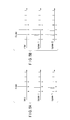
- FIGURE 5A illustrates a single odd pixel case to be processed in a conventional process of total variation minimization according to prior art.
- a top diagram illustrates a single pixel b with respect to neighboring pixels a and c, and the value of the single pixel b is assumed to be exceedingly higher from its true value in the initial state.
- Update I the value of the single pixel b is now reduced as illustrated in Update I by a solid line with respect to the original value in a dotted line.
- Update II After a second update in the discrete total variation minimization, the value of the single pixel b is further reduced as illustrated in Update II by a solid line with respect to the original value in a dotted line and the first updated value in a double dotted line.
- FIGURE 5B illustrates an odd pixel cluster case to be processed in a process of the discrete total variation minimization according.
- a top diagram illustrates a pixels 2 and 3 with respect to neighboring pixels 1 and 4, and the values of the pixels 2 and 3 are assumed to be exceedingly higher from its true value in the initial state.
- the value of the single pixel 2 is now reduced as illustrated in Update I by a solid line with respect to the original value in a dotted line.
- Update II the value of the single pixel 3 is now reduced as illustrated in Update II by a solid line with respect to the original value in a dotted line.
- FIGURES 5A and 5B since only one pixel value is updated, in case of cluster of pixels to be adjusted, it takes longer to process a cluster. That is, odd cluster coverage is generally slower than single pixel coverage.
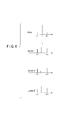
- FIGURE 6 illustrates an exemplary pixel case to be processed by the discrete TV minimization technique with a one-direction condition as used in an exemplary process of the Total Variation Iterative Reconstruction (TV-IR) according to the current invention.
- a pixel value increases or decreases as determined by the gradient at each step.
- the one-direction condition is that each pixel value only increases or decreases according to a non-zero gradient value as decided in the first step. In other words, the directional change remains the same during the discrete total variation minimization and cannot be subsequently changed in the one-direction condition according to the current invention.
- a top diagram illustrates a single pixel i with respect to neighboring pixels i-1 and i+1, and the value of the single pixel i is assumed to be exceedingly higher from its true value in the initial state. That is, the pixel i should be decreased, and the direction index is set to indicate a decrease in the first total variation minimization step.
- the value of the single pixel i is now reduced as illustrated in Update I by a solid line with respect to the original value in a dotted line.
- the value of the single pixel i is further reduced as illustrated in Update II by a solid line with respect to the original value in a dotted line and the first updated value in a double dotted line.
- the one-direction condition prevents the value of the single pixel i from increasing as illustrated in Update III by a dotted line with respect to the first updated value in a double dotted line.
- the value of the single pixel i remains as illustrated in Update II by a solid line with respect to the original value in a dotted line and the first updated value in a double dotted line.
- FIGURES 7A through 7D illustrate that the discrete TV minimization technique processes various exemplary cases in one embodiment of the Total Variation Iterative Reconstruction (TV-IR) process according to the current invention.
- the discrete total variation in 1-dimensional discrete distribution is defined by Equation (1).
- TV ⁇ i f i + 1 - f i
- Equation (2) The total variation minimization is defined by Equation (2).
- f i n f i n - 1 - a ⁇ ⁇ TV ⁇ f i
- the discrete gradient of total variation is substantially synonymous with the gradient of discrete total variation and is defined by Equations (3) and (4) in the current application.
- Equation (4) is either one of -2, 0 and +2.
- the gradient direction for a 3D image f(i,j,k) is determined by a function gtv along a predetermined direction as seen in Equation (5).
- gtv i ⁇ j ⁇ k sgn ⁇ f ⁇ i - 1 , j , k - f i ⁇ j ⁇ k + sgn ⁇ f ⁇ i + 1 , j , k - f i ⁇ j ⁇ k + sgn ⁇ f ⁇ i , j - 1 , k - f i ⁇ j ⁇ k + sgn ⁇ f ⁇ i , j + 1 , k - f i ⁇ j ⁇ k
- Equation (5) is either one of -4, -2, 0, +2 and +4 as index k is an image slice index.
- the 3D TV gradient for a 3D image f(i,j,k) at a predetermined point is either one of -6, -4, -2, 0, +2, +4 and +6.
- an integer m is determined to eliminate a dot at (i,j,k) and the m is defined by Equation (6).
- m ⁇ 1 a ⁇ min ⁇ f ⁇ i - 1 , j , k - f i ⁇ j ⁇ k ⁇ f ⁇ i + 1 , j , k - f i ⁇ j ⁇ k ⁇ where a is the predetermined value and the m is larger than a predetermined threshold m 0 , a point of f(i,j,k) is an isolated noise dot.
- f(i,j,k) f(i,j,k)+ma/2gtv(i,j,k).
- a dot value m is determined to eliminate a dot at (i,j,k) and the m is defined by Equation (7).
- m 1 a ⁇ min ⁇ f ⁇ i - 1 , j , k - f i ⁇ j ⁇ k ⁇ f ⁇ i + 1 , j , k - f i ⁇ j ⁇ k ⁇ f ⁇ i , j - 1 , k - f i ⁇ j ⁇ k ⁇ f ⁇ i , j + 1 , k - f i ⁇ j ⁇ k .
- a is the predetermined value and m is larger than a predetermined threshold m 0
- a point of f(i,j,k) is an isolated noise dot.
- Eqs. (5) and (7) can be generalized to a predetermined volume for a 3D image f(l,j,k).
- FIGURE 7A a first signal preservation pattern is illustrated for an exemplary set of pixel values in the discrete total variation minimization.
- the updated pixel values in the second pixel i remain the same as illustrated in an update bottom diagram of FIGURE 7A .
- the TV gradient values for the pattern in FIGURE 7A are usually not zero because of the continuous image model.
- the pixel values will be updated with a non-zero value and the pattern will be changed, which may result in edge blurring.
- FIGURE 7B a second signal preservation pattern is illustrated for an exemplary set of pixel values in the total variation minimization.
- the pixel value increases from a first pixel i-1 to a second pixel i, but the pixel value decreases from the second pixel i to a third pixel i+1 as illustrated in a top diagram of FIGURE 7B .
- Equations (9) respectively show that the pixel values are increasing and then decreasing while the gradient is two according to Eq. (4).
- f i - 1 ⁇ f i ⁇ f i + 1 , ⁇ TV ⁇ f i 2
- the second pixel i decreases its value after the discrete total variation minimization as illustrated in an update bottom diagram of FIGURE 7B .
- FIGURE 7C a third signal preservation pattern is illustrated for an exemplary set of pixel values in the total variation minimization.
- the three pixel values decrease from a first pixel i-1 to a second pixel i and from the second pixel i to a third pixel i+1 as illustrated in a top diagram of FIGURE 7C . That is, Equations (10) respectively show that the pixel values are decreasing while the gradient is zero.
- f i - 1 > f i > f i + 1 , ⁇ TV ⁇ f i 0
- FIGURE 7D a fourth signal preservation pattern is illustrated for an exemplary set of pixel values in the total variation minimization.
- the pixel value decreases from a first pixel i-1 to a second pixel i, but the pixel value increases from the second pixel i to a third pixel i+1 as illustrated in a top diagram of FIGURE 7D . That is, Equations (11) respectively show that the pixel values are decreasing and then increasing while the gradient is minus two.
- f i - 1 > f i , f i ⁇ f i + 1 , ⁇ TV ⁇ f i - 2
- the second pixel i increases its value after the discrete total variation minimization as illustrated in an update bottom diagram of FIGURE 7D .
- FIGURE 8A illustrates an image that has been reconstructed from projection data and has a high level of noise that is distributed in a non-uniform manner in the image.
- FIGURE 8B illustrates an image that has been denoised from FIGURE 8A using the discrete total variation minimization.
- the total variation minimization has been utilized without the above described one-direction condition according to the current invention. Consequently, although the image shows that the total variation minimization has reduced the noise to some extent, some regions of the image appear overcompensated or excessively smoothed after denoting. These excessively smoothed regions initially had a relatively low level of noise.
- FIGURE 8C illustrates an exemplary image that has been denoised from FIGURE 8A using the discrete total variation minimization with the one-direction condition according to the current invention.
- the discrete total variation minimization has been utilized with the above described one-direction condition according to the current invention. Consequently, the reconstructed image shows that the discrete total variation minimization has substantially reduced the noise without overcompensating or excessively smoothing the regions initially containing a relatively low level of noise.
- FIGURE 9A a graph illustrates a series of pixels across an edge and their pixel values in CT numbers in the original image as indicated by a solid line, after the discrete total variation (DTV) minimization as indicated by a dotted line and after the total variation (TV) minimization as indicated by a point-dot line.
- DTV discrete total variation
- TV total variation
- FIGURE 9B is a plot illustrating an enlarged edge portion of the pixels in the blue rectangular box in FIGURE 9A .
- the enlarged portion of the pixel values is substantially equal between the original image and after the discrete total variation (DTV) minimization as indicated by a single dotted line.
- the enlarged portion of the pixel values are slightly different from those after the total variation (TV) minimization as indicated by a single point-dot line.
- the inventive concept of the current invention includes potentially independent methods and systems that do not necessarily require a combination of features including the discrete gradients of total variation (DTV) minimization and the one-direction condition with respect to a particular reconstruction algorithm.
- DTV discrete gradient of total variation
- the technique of applying the discrete gradient of total variation (DTV) minimization alone without the one-direction condition is utilized with either a predetermined iterative reconstruction algorithm or a predetermined analytical reconstruction algorithm.
- the technique of applying the one-direction condition alone without the discrete gradient of total variation (DTV) minimization is utilized with either a predetermined iterative reconstruction algorithm or a predetermine analytical reconstruction algorithm.
- DTV discrete total variation
- TV conventional total variation
- the above features have some distinguishable effects on the image according to the current invention.
- the one-direction condition improves noise uniformity in the denoised images and avoids over smoothing in the low noise regions in an image, assuming that the image originally has an unequal noise distribution.
- the DTV minimization results in an improved edge preserving effects in comparison to the conventional TV minimization.
- the pixel values on an edge will not be substantially affected after a certain denoising treatment.
- the difference between the DTV minimization and the conventional TV minimization is substantially negligible for strong edges while the DTV minimization substantially improves in preserving the weak edges.
- DTV keeps the original values while TV slightly smoothes the values for the pixel near the bottom and top of edges.
Landscapes
- Physics & Mathematics (AREA)
- General Physics & Mathematics (AREA)
- Engineering & Computer Science (AREA)
- Theoretical Computer Science (AREA)
- Image Processing (AREA)
- Apparatus For Radiation Diagnosis (AREA)
- Image Analysis (AREA)
- Algebra (AREA)
- Mathematical Analysis (AREA)
- Mathematical Optimization (AREA)
- Mathematical Physics (AREA)
- Pure & Applied Mathematics (AREA)
Abstract
Description
- The current invention is generally related to an image processing method and system for image denoising which is optionally used in combination with an iterative reconstruction algorithm.
- For image reconstruction in CT, an iterative algorithm may include a total variation (TV) minimization. For example, some techniques have been based upon the ordered subset simultaneous algebraic reconstruction technique (OSSART), and the simultaneous algebraic reconstruction (SART). The TV minimization may also be applied to images reconstructed with an analytical algorithm such as filtered backprojection (FBP), to reduce the noise.
- Despite the prior art efforts, some problems remain unsolved and require improvement. Prior art efforts generally reduce noise quite uniformly in images except for edges. In other words, although the noise may be reduced based upon a total variation (TV) minimization, the resultant image may be excessively smoothed in some regions while the other regions may be still noisy if the original image has a non-uniform distribution. On the other hand, when prior art is applied to images with subtle edges, the edges may be smoothed out. It appears that prior art total variation (TV) minimization cannot improve the noise without sacrificing spatial resolution in some cases an original image has a non-uniform noise distribution that is common in clinical applications.
- Furthermore, there are some odd pixel clusters in noisy images where the HU values are 2σ to 3σ off the mean value and are far from their true values. TV minimization leaves these clusters as black/white dots in the denoised images because (1) the "cluster effect" slows down the denoising and (2) the original HU values are far from the true values.
- In view of the above discussed prior art problems, a practical solution is still desired for implementing a total variation (TV) minimization algorithm to avoid the overcompensation in the low noise regions and reduce the dots in the high noise pixel clusters.
-
-
FIGURE 1 is a diagram illustrating one embodiment of the multi-slice X-ray CT apparatus or scanner according to the current invention. -
FIGURE 2 is a flow chart illustrating steps involved in a preferred process of the Total Variation Iterative Reconstruction (TV-IR) according to the current invention. -
FIGURE 3 is a flow chart illustrating steps involved in the ordered subset simultaneous algebraic reconstruction technique (OSSART) as used in a preferred process of the Total Variation Iterative Reconstruction (TV-IR) according to the current invention. -
FIGURE 4 is a flow chart illustrating steps involved in the discrete TV minimization technique as used in a preferred process of the Total Variation Iterative Reconstruction (TV-IR) according to the current invention. -
FIGURE 5A illustrates a single odd pixel case to be processed in a conventional process of total variation minimization according to prior art. -
FIGURE 5B illustrates an odd pixel cluster case to be processed in a process of total variation minimization according to prior art. -
FIGURE 6 illustrates an exemplary pixel case to be processed by the discrete TV minimization technique as used in a preferred process of the Total Variation Iterative Reconstruction (TV-IR) according to the current invention. -
FIGURES 7A through 7D illustrate various exemplary cases to be processed by the discrete TV minimization technique as used in a preferred process of the Total Variation Iterative Reconstruction (TV-IR) according to the current invention. -
FIGURE 8A illustrates an image that has been reconstructed from projection data and has a high level of noise that is distributed in a non-uniform manner in the image. -
FIGURE 8B illustrates an image that has been reconstructed using the total variation iterative reconstruction (TV-IR). -
FIGURE 8C illustrates an exemplary image that has been reconstructed using the total variation iterative reconstruction (TV-IR) with the one-direction condition according to the current invention. -
FIGURE 9A is a graph illustrating a series of pixels across an edge and their pixel values in CT numbers in the original image, after the discrete total variation (DTV) minimization and after the total variation (TV) minimization. -
FIGURE 9B is a plot illustrating an enlarged edge portion of the pixels in the blue rectangular box inFIGURE 9A . - Referring now to the drawings, wherein like reference numerals designate corresponding structures throughout the views, and referring in particular to
FIGURE 1 , a diagram illustrates one embodiment of the multi-slice X-ray CT apparatus or scanner according to the current invention including agantry 100 and other devices or units. Thegantry 100 is illustrated from a front view and further includes anX-ray tube 101, anannular frame 102 and a multi-row or two-dimensional arraytype X-ray detector 103. TheX-ray tube 101 andX-ray detector 103 are diametrically mounted across a subject S on theannular frame 102, which rotates around axis RA. A rotatingunit 107 rotates the frame I02 at a high speed such as 0.27 sec/rotation while the subject S is being moved along the axis RA into or out of the illustrated page. - The multi-slice X-ray CT apparatus further includes a
high voltage generator 109 that applies a tube voltage to theX-ray tube 101 so that theX-ray tube 101 generates X ray. In one embodiment, thehigh voltage generator 109 is mounted on theframe 102. The X rays are emitted towards the subject S, whose cross sectional area is represented by a circle. TheX-ray detector 103 is located at an opposite side from theX-ray tube 101 across the subject S for detecting the emitted X rays that have transmitted through the subject S. - Still referring to
FIGURE 1 , the X-ray CT apparatus or scanner further includes other devices for processing the detected signals fromX-ray detector 103. A data acquisition circuit or a Data Acquisition System (DAS) 104 converts a signal output from theX-ray detector 103 for each channel into a voltage signal, amplifies it, and further converts it into a digital signal. TheX-ray detector 103 and theDAS 104 are configured to handle a predetermined total number of projections per rotation (TPPR). - The above described data is sent to a preprocessing
device 106, which is housed in a console outside thegantry 100 through anon-contact data transmitter 105. The preprocessingdevice 106 performs certain corrections such as sensitivity correction on the raw data. Astorage device 112 then stores the resultant data that is also called projection data at a stage immediately before reconstruction processing. Thestorage device 112 is connected to asystem controller 110 through a data/control bus, together with areconstruction device 114, a discrete total variation (TV)minimization device 117, adisplay device 116, aninput device 115, and a scanplan support apparatus 200. The scanplan support apparatus 200 includes a function for supporting an imaging technician to develop a scan plan. - One embodiment of the
reconstruction device 114 and the discrete total variation (TV)minimization device 117 further include various software and hardware components. According to one aspect of the current invention, thereconstruction device 114 of the CT apparatus reconstructs an image while the discreteTV minimization device 117 advantageously minimizes total variation. In general, thereconstruction device 114 and the discreteTV minimization device 117 in one embodiment of the current invention perform the total variation iterative reconstruction (TVIR) algorithm for reconstructing an image. In further detail, thereconstruction device 114 performs on the projection data an ordered subset simultaneous algebraic reconstruction technique (OSSART) process while the discreteTV minimization device 117 performs a TV minimization process. One embodiment of thereconstruction device 114 and the discreteTV minimization device 117 respectively perform the two processes that are implemented in a main loop where a first predetermined number of iterations is prescribed and in an inner loop where a second predetermined number of iterations is prescribed. In another embodiment, the discreteTV minimization device 117 repeats the inner loop until a predetermined certain condition is achieved. - Before the TV minimization process, the
reconstruction device 114 performs on the projection data an ordered subsets simultaneous algebraic reconstruction technique (OSSART). The projection data is grouped into a predetermined number of subsets N each having a certain number of views. During the OSSART, each subset may be sequentially processed in one embodiment. In another embodiment, a plurality of the subsets may be processed in parallel by taking advantage of certain microprocessor such as multiple central processing units (CPU) or a graphics processing unit (GPU). In yet another embodiment, thereconstruction device 114 performs on the projection data an ordered subsets simultaneous algebraic reconstruction technique (OSSART) with a relaxation parameter. - During the ordered subsets simultaneous algebraic reconstruction technique (OSSART), the
reconstruction device 114 also performs two major operations. Namely, for each subset N, thereconstruction device 114 re-projects the image volume to form the computed projection data and back-projects the normalized difference between the measured projection and the computed projection data to reconstruct an updated image volume when added to the current image estimate. In further detail, one embodiment of thereconstruction device 114 re-projects the image volume by using the ray tracing technique where no coefficient of the system matrix is cached. Moreover, one embodiment of thereconstruction device 114 simultaneously re-projects all rays in a subset, and this is optionally implemented in parallel. Other embodiments include the system model and the noise model. In the back-projection, one embodiment of thereconstruction device 114 uses a pixel-driven technique to back-project all of the normalized difference projection data in a subset to form the desired updated image volume. Because thereconstruction device 114 back-projects all ray sums, i.e., difference projection data, in a subset to form an image volume, this operation is optionally implemented in parallel too. These operations are applied to every subset N to complete a single OSSART step. This and other embodiments are optionally included in the scope of the current invention as more particularly claimed in the appended claims. - In the total variation (TV) minimization process, one embodiment of the discrete
TV minimization device 117 employs discrete TV minimization with a predetermined step parameter and step number - for adjusting a given pixel value. The one-direction condition is applied optionally. As will be described with respect toFIGURE 6 , the predetermined one-direction condition reduces noise in high noise regions while it avoids certain low noise regions from being overcompensated or excessively smoothed. In the discrete TV minimization, if a pixel is on an edge, the pixel value will remain exactly the same before and after denoising. In other words, one embodiment of the discreteTV minimization device 117 substantially reduces blur edges in images. Furthermore, one embodiment of the discreteTV minimization device 117 substantially improves unnatural noise texture in the denoised image especially after strong noise reduction. One embodiment of the discreteTV minimization device 117 terminates discrete TV minimization upon reaching a certain predetermined condition. One exemplary termination condition is the zero gradients due to the one-direction condition while another example is a predetermined number of repetitions of the discrete TV minimization. - In the above described multi-slice X-ray CT apparatus or scanner according to the current invention, one embodiment of the
reconstruction device 114 reconstructs an image based upon an iterative reconstruction technique. Another one embodiment of thereconstruction device 114 reconstructs an image based upon an analytical reconstruction technique such as filtered backprojection (FBP). Furthermore, the above described embodiment of the multi-slice X-ray CT apparatus or scanner according to the current invention includes separate devices for thereconstruction device 114 and the discreteTV minimization device 117. In another embodiment, thereconstruction device 114 and the discreteTV minimization device 117 are optionally a single device including a combination of software and hardware. The current invention is practiced to improve noise texture after noise reduction based upon the discrete TV minimization with one-direction condition without limiting to any particular set of hardware or software implementations. - Now referring to
FIGURE 2 , a flow chart illustrates steps involved in an exemplary process of total variation iterative reconstruction (TV-IR) according to the current invention. In an initialization step S10, an image X0 is initialized to 0. In the same step, a value indicating a number of iteration is initialized to a first predetermined number K, and a current number of iterations is kept in an iteration counter or a main-loop counter k. In a step S20, an ordered subset simultaneous algebraic reconstruction technique (OSSART) with a relaxation parameter is performed on the measured projection data in an exemplary process of the TV-IR according to the current invention. The step S20 outputs an intermediate image X1. The detailed steps of the OSSART will be further described with respect toFIGURE 3 below. - Still referring to
FIGURE 2 , the illustrated exemplary process includes two loops where certain steps are repeated and or iteratively performed. The first loop is the main or outer loop that includes steps S20, S30 and S40. The main loop is repeated according to the first predetermined number K that is assigned to the main-loop counter k in the step S10 according to the exemplary process. As each repetition of the main loop is completed, the main-loop counter k is decremented by one from the initial value K. In one exemplary process, the first predetermined number K is optionally determined based upon a number of ordered subsets Nsets of the projection data, which will be further described with respect toFIGURE 3 . Within the main loop, an ordered subsets simultaneous algebraic reconstruction technique (OSSART) with relaxation parameter lambda is applied to projection data in a step S20. A weight value is stored in a relaxation parameter λ for the OSSART. - The second loop is the sub or inner loop that includes the steps S30 and S40. The sub loop is also called a total variation step (TVstep) loop. The sub loop is repeated according to a second predetermined number S that is also assigned to a total variation counter or a sub-loop counter s in one embodiment. The steps S30 and S40 are repeated in the sub loop for the assigned second number of times S in the one embodiment. As each repetition of the sub loop is completed, the sub-loop counter s is decremented by one from the initial value S. In another embodiment, the steps S30 and S40 are repeated in the sub loop are repeated until a predetermined condition is reached.
- In the step S30, a discrete total variation minimization technique is iteratively performed in order to minimize the total variation based upon a predetermined technique. As the step S30 is finished, an image X2 is generated from the intermediate image X1 from the step S20. The image generated in the step S30 is assigned to an intermediate image holder or variable X1 in the step S40.
- In a step S42, it is decided based upon the sub-loop counter s or a predetermined termination condition as to whether or not the sub loop is completed. If it is decided that the sub loop is completed in the step S42, it is further determined in a S44 as to whether or not the steps S20 through S40 are to be repeated in the main loop. On the other hand, if it is decided in the step S42 that the sub loop is not yet completed, the steps S30 and S40 are repeated in the sub loop.
- In the step S44, it is decided based upon the main loop counter k as to whether not the main loop is completed. If it is decided that the main loop is completed in the step S44, the image X2 is outputted in a step S50. On the other hand, if it is decided in the step S44 that the main loop is not yet completed, the steps S20, S30 and S40 are repeated in the main loop.
- Now referring to
FIGURE 3 , a flow chart illustrates further acts or sub steps in the step S20 ofFIGURE 2 , and these steps are involved in the ordered subset simultaneous algebraic reconstruction technique (OSSART) with a relaxation parameter as used in an exemplary process of the total variation iterative reconstruction (TV-IR) according to the current invention. The illustrated process of the OSSART includes one loop where certain steps are repeated and iteratively performed. The loop includes steps S23, S24 and S25 and is repeated according to a predetermined number Nsets rather than a certain condition is met. When the loop is finished, the OSSART outputs the intermediate image in the variable X1 in a step S27. - Still referring to
FIGURE 3 , each of the steps S21 through S26 will be generally described below. In a step S21, the image X0 and measured projection data p are available from through the step S20 ofFIGURE 2 . In one optional implementation, one of the stored weight values in the first predetermined record structure is selected based on an index k that corresponds to a value of the main-loop counter k of the main loop and is assigned to the relaxation parameter λ. - In a step S22, the measured projection data p is partitioned into Nsets groups called subsets. The number of subsets Nsets is based upon a certain rule that the total number of views is divided by a predetermined number of subviews. For example, if the projection data have 1200 views in total and a predetermined number of subviews is 15, a number of subsets is 80 (1200/15=80). Alternatively, the number of views in each subset optionally changes. For a fixed number of total views, if a number of subsets is relatively small due to a large number of subviews, the image will converge slowly and requires more iterations in the main loop. On the other hand, if a number of subsets is relatively large due to a small number of subviews, the image will converge fast and requires less iterations. At the same time, the image includes more noise. Based upon the above relationship, a value of the first predetermined number K is optionally modified in the step S10 of
FIGURE 2 . - Each of the subsets Nsets contains a number of subrays Nsubrays, which is determined by dividing a total number of arrays Nrays by the subsets Nsets. For each of the subsets Nsets, a step S23 re-projects the image X0 to form the computed projection data while a step S24 back-projects the normalized difference between the measured projection data and the computed projection data. In further detail, one exemplary process of the step S23 re-projects the image volume by using the ray tracing technique where no coefficient of the system matrix is cached. Moreover, one embodiment of the step S23 simultaneously re-projects all rays in a subset, and this is optionally implemented in parallel. In the back-projection, one embodiment of the S24 uses a pixel-driven technique to back-project all of the normalized difference projection data in a subset to form the desired updated image volume. Because the step S24 back-projects all ray sums, i.e., the normalized difference projection data, in a subset to form an image volume, this operation is optionally implemented in parallel. These operations are applied to every subset Nsets to complete a single OSSART step. After a subset counter is initialized to Nsets, the subset counter is decremented by one as each operation is completed.
- Still referring to
FIGURE 3 , a step S25 updates the image X0 by adding the weighted back-projected image from the step S24 to the image X0. To weight the back-projected image, the relaxation parameter λ is used as will be further described with respect toFIGURE 6 . Consequently, it is determined in a step S26 as to whether or not the Nsets have been already completed. If it is determined based upon the step S26 that the Nsets have not already completed, the loop is repeated by proceeding to the step S23. On the other hand, if it is determined in the step S26 that the Nsets have already completed, the image generated in the step S25 is assigned to an intermediate image holder or variable X1 before the image XI is outputted in a step S27. - Now referring to
FIGURE 4 , a flow chart illustrates further steps of the step S30 inFIGURE 2 , and these steps include the discrete total variation (TV) minimization technique as used in a process of the total variation iterative reconstruction (TV-IR) according to the current invention. The illustrated process of the discrete TV minimization technique includes the sub loop where certain steps are repeated and iteratively performed. The sub loop includes steps S110 through S160 and is repeated for a predetermined number of times and or until a certain condition is met. When the sub loop is finished, the discrete TV minimization technique returns the image in the variable X2. - Still referring to
FIGURE 4 , each of the steps S100 through S170 will be generally described below. In a step S100, a direction index DI is initialized to a predetermined value such as 0 for each pixel. Thepredetermined value 0 in this case signifies a mixed state of an increase and a decrease (which state is also referred to as "unknown") in directional change for the total variation for a given pixel. By the same token, apredetermined value 1 signifies an increase in directional change for the total variation for a given pixel while a predetermined value -1 signifies a decrease in directional change for the total variation for a given pixel. In a step S110, a gradient Gr of total variation (TV) is determined for a given pixel i and the corresponding value is stored in GR[i]. The sign of the gradient GR of total variation indicates an increase by +1, a decrease by -1 or a mixed state by 0 for a given pixel i. For the corresponding pixel i, it is determined in a step S120 as to whether or not the direction index DI[i] is 0 or a mixed state, as initialized. If it is determined in the step S120 that the direction index DI[i] is 0 or mixed, the direction index DI[i] is updated to the corresponding sign of the gradient GR[i] in a step S130. That is, if the gradient GR of total variation is larger than zero, an increase value +1 is assigned to the direction index DI[i]. Similarly, if the gradient GR of total variation is less than zero, a decrease value -1 is assigned to the direction index DI[i]. Lastly, if the gradient GR of total variation is zero, amixed state value 0 is assigned to the direction index DI[i]. Following the step S130, the exemplary process of the discretion total variation minimization proceeds to a step S140. On the other hand, if it is determined in the step S120 that the direction index DI[i] is not 0 or mixed, the direction index DI[i] is not updated in the step S130 and the exemplary process of the discretion total variation minimization proceeds to a step S140. - Still referring to
FIGURE 4 , the exemplary process of the discretion total variation minimization further determines in the step S140 as to whether or not the direction index DI[i] and the gradient Gr[i] have the same sign for a given pixel i. If it is determined in the step S140 that the direction index DI[i] and the gradient Gr[i] have the same sign, the pixel value for the given pixel i is updated with a predetermined constant in a step S150. An exemplary value of the predetermined constant is an estimated standard deviation StdD in the original image divided by N, where N ranges from 10 to 100. Following the step S150, the exemplary process of the discretion total variation minimization proceeds to a step S160. On the other hand, if it is determined in the step S140 that the direction index DI[i] and the gradient Gr[i] do not have the same sign, the pixel value i is not updated in the step S950 and the exemplary process of the discretion total variation minimization proceeds to the step S160. - The discretion total variation minimization is terminated according to a predetermined rule. In the step S160, it is determined as to whether or not all of the pixels in the image have been processed. If it is determined that all of the pixels in the image have not yet been processed, the exemplary process of the discretion total variation minimization proceeds back to the
step 110 for the remaining and unprocessed pixels. On the other hand, if it is determined that all of the pixels in the image have been already processed, the exemplary process of the discretion total variation minimization proceeds to a step S170, where an additional termination condition is examined. In one embodiment of the discretion total variation minimization process, one predetermined termination condition is that the direction index DI[i] and the gradient Gr[i] have a different sign in every pixel as illustrated in a step S170. If it is determined in the step S170 that any of the pixels in the image fail to have a different sign in the direction index DI[i] and the gradient Gr[i], the exemplary process of the discretion total variation minimization proceeds back to the step S110 for additional processing. On the other hand, if it is determined in the step S170 that all of the pixels in the direction index DI[i] and the gradient Gr[i] have a different sign, the exemplary process of the discretion total variation minimization terminates. - In an alternative embodiment of the discretion total variation minimization process, the termination condition in the step S170 is achieved by reaching a predetermined number of repetitions of the steps S110 through S150 in lieu of the different sign in the direction index DI[i] and the gradient Gr[i] of every pixel. If it is determined in the step S170 that a predetermined number of repetitions is not yet achieved, the exemplary process of the discretion total variation minimization proceeds back to the step S110 for additional processing. One exemplary predetermined number of iterations N is defined by an estimated standard deviation StdD in the original image divided by a constant C, where the constant C is the estimated standard deviation in the denoised image. On the other hand, if it is determined in the step S170 that a predetermined number of repetitions is achieved, the exemplary process of the discretion total variation minimization terminates. The above described exemplary and alternative embodiments are not limiting the discrete total variation process according to the current invention.
-
FIGURE 5A illustrates a single odd pixel case to be processed in a conventional process of total variation minimization according to prior art. A top diagram illustrates a single pixel b with respect to neighboring pixels a and c, and the value of the single pixel b is assumed to be exceedingly higher from its true value in the initial state. After a first update in the discrete total variation minimization, the value of the single pixel b is now reduced as illustrated in Update I by a solid line with respect to the original value in a dotted line. After a second update in the discrete total variation minimization, the value of the single pixel b is further reduced as illustrated in Update II by a solid line with respect to the original value in a dotted line and the first updated value in a double dotted line. -
FIGURE 5B illustrates an odd pixel cluster case to be processed in a process of the discrete total variation minimization according. A top diagram illustrates apixels pixels pixels single pixel 2 is now reduced as illustrated in Update I by a solid line with respect to the original value in a dotted line. After a second update in the discrete total variation minimization, the value of thesingle pixel 3 is now reduced as illustrated in Update II by a solid line with respect to the original value in a dotted line. As seen inFIGURES 5A and 5B , since only one pixel value is updated, in case of cluster of pixels to be adjusted, it takes longer to process a cluster. That is, odd cluster coverage is generally slower than single pixel coverage. -
FIGURE 6 illustrates an exemplary pixel case to be processed by the discrete TV minimization technique with a one-direction condition as used in an exemplary process of the Total Variation Iterative Reconstruction (TV-IR) according to the current invention. In general, a pixel value increases or decreases as determined by the gradient at each step. The one-direction condition is that each pixel value only increases or decreases according to a non-zero gradient value as decided in the first step. In other words, the directional change remains the same during the discrete total variation minimization and cannot be subsequently changed in the one-direction condition according to the current invention. - Still referring to
FIGURE 6 , a top diagram illustrates a single pixel i with respect to neighboring pixels i-1 and i+1, and the value of the single pixel i is assumed to be exceedingly higher from its true value in the initial state. That is, the pixel i should be decreased, and the direction index is set to indicate a decrease in the first total variation minimization step. After a first total variation minimization step, the value of the single pixel i is now reduced as illustrated in Update I by a solid line with respect to the original value in a dotted line. After a second total variation minimization step, the value of the single pixel i is further reduced as illustrated in Update II by a solid line with respect to the original value in a dotted line and the first updated value in a double dotted line. After a third total variation minimization step, the one-direction condition prevents the value of the single pixel i from increasing as illustrated in Update III by a dotted line with respect to the first updated value in a double dotted line. In other words, after the third update III, the value of the single pixel i remains as illustrated in Update II by a solid line with respect to the original value in a dotted line and the first updated value in a double dotted line. -
FIGURES 7A through 7D illustrate that the discrete TV minimization technique processes various exemplary cases in one embodiment of the Total Variation Iterative Reconstruction (TV-IR) process according to the current invention. In general, the discrete total variation in 1-dimensional discrete distribution is defined by Equation (1).
- The total variation minimization is defined by Equation (2).

- Where n is 1, 2, 3 ..... and a is a constant. The discrete gradient of total variation is substantially synonymous with the gradient of discrete total variation and is defined by Equations (3) and (4) in the current application.

- For one dimension, the value of Equation (4) is either one of -2, 0 and +2.
- By the same token, the gradient direction for a 3D image f(i,j,k) is determined by a function gtv along a predetermined direction as seen in Equation (5).

- For two dimension, the value of Equation (5) is either one of -4, -2, 0, +2 and +4 as index k is an image slice index. Similarly, the 3D TV gradient for a 3D image f(i,j,k) at a predetermined point is either one of -6, -4, -2, 0, +2, +4 and +6.
- Furthermore, an integer m is determined to eliminate a dot at (i,j,k) and the m is defined by Equation (6).

where a is the predetermined value and the m is larger than a predetermined threshold m0, a point of f(i,j,k) is an isolated noise dot. The isolated noise dot is eliminated by f(i,j,k)=f(i,j,k)+ma/2gtv(i,j,k). Similarly, a dot value m is determined to eliminate a dot at (i,j,k) and the m is defined by Equation (7).
where a is the predetermined value and m is larger than a predetermined threshold m0, a point of f(i,j,k) is an isolated noise dot. The isolated noise dot is eliminated by f(i,j,k)=f(i,j,k)+ma/4gtv(i,j,k). Similarly, Eqs. (5) and (7) can be generalized to a predetermined volume for a 3D image f(l,j,k). - Now referring to
FIGURE 7A , a first signal preservation pattern is illustrated for an exemplary set of pixel values in the discrete total variation minimization. In an initial state of the pixel values, the three pixel values increase from a first pixel i-1 to a second pixel i and from the second pixel i to a third pixel i+1 as illustrated in a top diagram ofFIGURE 7A . That is, Equations (8) respectively show that the pixel values are increasing while the gradient is zero.
- Consequently, after discrete total variation minimization, the updated pixel values in the second pixel i remain the same as illustrated in an update bottom diagram of
FIGURE 7A . In the conventional TV minimization, the TV gradient values for the pattern inFIGURE 7A are usually not zero because of the continuous image model. The pixel values will be updated with a non-zero value and the pattern will be changed, which may result in edge blurring. - Now referring to
FIGURE 7B , a second signal preservation pattern is illustrated for an exemplary set of pixel values in the total variation minimization. In an initial state of the pixel values, the pixel value increases from a first pixel i-1 to a second pixel i, but the pixel value decreases from the second pixel i to a third pixel i+1 as illustrated in a top diagram ofFIGURE 7B . That is, Equations (9) respectively show that the pixel values are increasing and then decreasing while the gradient is two according to Eq. (4).
- Consequently, the second pixel i decreases its value after the discrete total variation minimization as illustrated in an update bottom diagram of
FIGURE 7B . - Now referring to
FIGURE 7C , a third signal preservation pattern is illustrated for an exemplary set of pixel values in the total variation minimization. In an initial state of the pixel values, the three pixel values decrease from a first pixel i-1 to a second pixel i and from the second pixel i to a third pixel i+1 as illustrated in a top diagram ofFIGURE 7C . That is, Equations (10) respectively show that the pixel values are decreasing while the gradient is zero.
- Consequently, after the discrete total variation minimization, the updated pixel values in the second pixel i remain the same as illustrated in an update bottom diagram of
FIGURE 7C . - Now referring to
FIGURE 7D , a fourth signal preservation pattern is illustrated for an exemplary set of pixel values in the total variation minimization. In an initial state of the pixel values, the pixel value decreases from a first pixel i-1 to a second pixel i, but the pixel value increases from the second pixel i to a third pixel i+1 as illustrated in a top diagram ofFIGURE 7D . That is, Equations (11) respectively show that the pixel values are decreasing and then increasing while the gradient is minus two.
- Consequently, the second pixel i increases its value after the discrete total variation minimization as illustrated in an update bottom diagram of
FIGURE 7D . -
FIGURE 8A illustrates an image that has been reconstructed from projection data and has a high level of noise that is distributed in a non-uniform manner in the image. -
FIGURE 8B illustrates an image that has been denoised fromFIGURE 8A using the discrete total variation minimization. The total variation minimization has been utilized without the above described one-direction condition according to the current invention. Consequently, although the image shows that the total variation minimization has reduced the noise to some extent, some regions of the image appear overcompensated or excessively smoothed after denoting. These excessively smoothed regions initially had a relatively low level of noise. -
FIGURE 8C illustrates an exemplary image that has been denoised fromFIGURE 8A using the discrete total variation minimization with the one-direction condition according to the current invention. The discrete total variation minimization has been utilized with the above described one-direction condition according to the current invention. Consequently, the reconstructed image shows that the discrete total variation minimization has substantially reduced the noise without overcompensating or excessively smoothing the regions initially containing a relatively low level of noise. - Now referring to
FIGURE 9A , a graph illustrates a series of pixels across an edge and their pixel values in CT numbers in the original image as indicated by a solid line, after the discrete total variation (DTV) minimization as indicated by a dotted line and after the total variation (TV) minimization as indicated by a point-dot line. A portion of the pixels that are on an edge is indicated by a blue rectangular box inFIGURE 9A. FIGURE 9B is a plot illustrating an enlarged edge portion of the pixels in the blue rectangular box inFIGURE 9A . The enlarged portion of the pixel values is substantially equal between the original image and after the discrete total variation (DTV) minimization as indicated by a single dotted line. On the other hand, the enlarged portion of the pixel values are slightly different from those after the total variation (TV) minimization as indicated by a single point-dot line. - As will be claimed, the inventive concept of the current invention includes potentially independent methods and systems that do not necessarily require a combination of features including the discrete gradients of total variation (DTV) minimization and the one-direction condition with respect to a particular reconstruction algorithm. For example, the technique of applying the discrete gradient of total variation (DTV) minimization alone without the one-direction condition is utilized with either a predetermined iterative reconstruction algorithm or a predetermined analytical reconstruction algorithm. By the same token, the technique of applying the one-direction condition alone without the discrete gradient of total variation (DTV) minimization is utilized with either a predetermined iterative reconstruction algorithm or a predetermine analytical reconstruction algorithm. Furthermore, the technique of the one-direction condition alone is combined with either a discrete total variation (DTV) minimization technique or a conventional total variation (TV) minimization technique. These examples are merely illustrative and are not limiting the inventive concept of denoising the images according to the current invention.
- In general, the above features have some distinguishable effects on the image according to the current invention. For example, the one-direction condition improves noise uniformity in the denoised images and avoids over smoothing in the low noise regions in an image, assuming that the image originally has an unequal noise distribution. On the other hand, the DTV minimization results in an improved edge preserving effects in comparison to the conventional TV minimization. Using DTV, the pixel values on an edge will not be substantially affected after a certain denoising treatment. The difference between the DTV minimization and the conventional TV minimization is substantially negligible for strong edges while the DTV minimization substantially improves in preserving the weak edges. Another distinction is that DTV keeps the original values while TV slightly smoothes the values for the pixel near the bottom and top of edges.
- It is to understood, however, that even though numerous characteristics and advantages of the present invention have been set forth in the foregoing description, together with details of the structure and function of the invention, the disclosure is illustrative only, and that although changes may be made in detail, especially in matters of shape, size and arrangement of parts, as well as implementation in software, hardware, or a combination of both, the changes are within the principles of the invention to the full extent indicated by the broad general meaning of the terms in which the appended claims are expressed.
Claims (28)
- A method of denoising an image, characterized by comprising the steps of:a) initializing (S100) a direction index associated with each of image pixels, the direction index indicating an increase, a decrease and a mixed state in gradient direction of total variation at a given pixel,;b) determining (S110) a discrete gradient of the total variation for each of the image pixels, the discrete gradient indicating the increase, the decrease or the mixed state;c) updating (S130) the direction index of each of the image pixels with the discrete gradient if the direction index is the mixed state;d) changing (S150) a pixel value of each of the image pixels by a predetermined value to reduce the total variation if the direction index and the discrete gradient are equal in the gradient direction for the one of the image pixels; ande) repeating (S160, S170) the steps b) through d) until a certain predetermined condition is reached.
- The method of denoising an image according to claim 1 characterized in that the certain predetermined condition is that the direction index and the discrete gradient are different in the gradient direction for each of the image pixels.
- The method of denoising an image according to claim 1 characterized in that the certain predetermined condition is a predetermined number of repetitions of the steps b) through d).
- The method of denoising an image according to claim 1 characterized in that the gradient direction for a 2D image f(i,j,k) in a predetermined direction is determined by a function gtv:

- The method of denoising an image according to claim 4 characterized in that a point of f(i,j,k) is an isolated noise dot when a dot value m is larger than a predetermined threshold m0.
- The method of denoising an image according to claim 5 characterized in that the dot value m is determined to eliminate the dot at (i,j,k) and the m is defined by:

where a is the predetermined value. - The method of denoising an image according to claim 6 characterized in that the isolated noise dot is eliminated by f(i,j,k)=f(i,j,k)+ma/2gtv(i,j,k).
- The method of denoising an image according to claim 5 characterized in that the dot value m is determined to eliminate the dot at (i,j,k) and the m is defined by:

where a is the predetermined value. - The method of denoising an image according to claim 8 characterized in that the isolated noise dot is eliminated by f(i,j,k)=f(i,j,k)+ma/4gtv(i,j,k).
- The method of denoising an image according to claim 1 characterized in that the steps a) through e) are performed in an iterative reconstruction technique.
- The method of denoising an image according to claim 1 characterized in that the steps a) through e) are performed in an analytic reconstruction technique.
- The method of denoising an image according to claim 1 characterized by further comprising the steps of:f) obtaining an image estimate from the measured data;g) forward projecting the image estimate using at least a single ray to generate reprojected data;h) determining a difference between the reprojected data and the measured data;i) updating the image estimate based upon the difference to generate an updated image, wherein the steps f) through i) are performed prior to the step a); andj) repeating the steps g) through i) using the updated image as the image estimate in the step g) and the steps a) through e).
- The method of denoising an image according to claim 1 characterized by further comprising the steps of:f) obtaining an image estimate from the measured data;g) forward projecting the image estimate using at least a single ray to generate reprojected data;h) determining a data difference between the reprojected data and the measured data;i) backprojecting the data difference to generate a difference image;j) performing the steps a) through e) on the difference image;k) updating the image estimate based upon the difference image to generate an updated image, wherein the steps f) through j) are performed prior to the step a); andl) repeating the steps g) through j) using the updated image as the image estimate in the step g) and the steps a) through e).
- A system for denoising an image, characterized by comprising:a reconstruction device (114) for reconstructing an image having image pixels from projection data; anda discrete Total Variation (TV) minimization unit (117) for setting a set of predetermined values respectively indicating an increase, a decrease and a mixed state in gradient direction of total variation at a given pixel, said discrete TV minimization unit initializing a direction index to the mixed state for each of image pixels, said discrete TV minimization unit determining a discrete gradient of the total variation for each of the image pixels, the discrete gradient indicating the increase, the decrease or the mixed state, said discrete TV minimization unit updating the direction index of each of the image pixels with the discrete gradient if the direction index is the mixed state, said discrete TV minimization unit changing a pixel value of each of the image pixels by a predetermined value to reduce the total variation if the direction index and the discrete gradient are equal in the gradient direction for the one of the image pixels, said discrete TV minimization unit repeating until a certain predetermined condition is reached.
- The system for denoising an image according to claim 14 characterized in that the certain predetermined condition is that the direction index and the discrete gradient are different in the gradient direction for each of the image pixels.
- The system for denoising an image according to claim 14 characterized in that the certain predetermined condition is that said discrete TV minimization unit completes a predetermined number of the repetitions.
- The system for denoising an image according to claim 14 characterized in that the gradient direction for a 3D image f(i,j,k) in a predetermined direction is determined by a function gtv:

- The system for denoising an image according to claim 17 characterized in that a point of f(i,j,k) is an isolated noise dot when a dot value m is larger than a predetermined threshold m0.
- The system for denoising an image according to claim 18 characterized in that the dot value m is determined to eliminate a dot at (i,j,k) and the dot value m is defined by:

where a is the predetermined value. - The system for denoising an image according to claim 19 characterized in that the isolated noise dot is eliminated by f(i,j,k)=f(i,j,k)+ma/2gtv(i,j,k).
- The system for denoising an image according to claim 18 characterized in that the dot value m is determined to eliminate a dot at (i,j,k) and the m is defined by:

where a is the predetermined value. - The system for denoising an image according to claim 21 characterized in that the isolated noise dot is eliminated by f(i,j,k)=f(i,j,k)+ma/4gtv(i,j,k).
- The system for denoising an image according to claim 14 characterized in that said reconstruction device performs an iterative reconstruction technique.
- The system for denoising an image according to claim 14 characterized in that said reconstruction device performs an analytic reconstruction technique.
- The system for denoising an image according to claim 14 characterized in that said reconstruction device obtains an image estimate from the measured data, said reconstruction device forward projecting the image estimate using at least a single ray to generate reprojected data, said reconstruction device determining a difference between the reprojected data and the measured data, said reconstruction device updating the image estimate based upon the difference to generate an updated image, said reconstruction device repeating using the updated image as the image estimate.
- The system for denoising an image according to claim 14 characterized in that said reconstruction device obtaining an image estimate from the measured data, said reconstruction device forward projecting the image estimate using at least a single ray to generate reprojected data, said reconstruction device determining a data difference between the reprojected data and the measured data, said reconstruction device backprojecting the data difference to generate a difference image, said reconstruction device updating the image estimate based upon the difference image to generate an updated image, said reconstruction device repeating using the updated image as the image estimate.
- A method of denoising an image, characterized by comprising the steps of:i) determining a discrete gradient of total variation for each of the image pixels, the discrete gradient indicating an increase, a decrease or a mixed state thereof;ii) changing a pixel value of each of the image pixels by a predetermined value according to the discrete gradient; andiii) repeating the steps i) and ii) until a predetermined condition is reached.
- A system for denoising an image, characterized by comprising:a reconstruction device for reconstructing an image having image pixels from projection data; anda discrete Total Variation (TV) minimization unit for determining a discrete gradient of total variation for each of the image pixels, the discrete gradient indicating an increase, a decrease or a mixed state thereof, said discrete Total Variation (TV) minimization unit changing a pixel value of each of the image pixels by a predetermined value according to the discrete gradient, said discrete Total Variation (TV) minimization unit repeating the determination of the discrete gradient and the change of the pixel value until a predetermined condition is reached.
Applications Claiming Priority (1)
| Application Number | Priority Date | Filing Date | Title |
|---|---|---|---|
| US13/354,851 US9147229B2 (en) | 2012-01-20 | 2012-01-20 | Method and system for image denoising using discrete total variation (TV) minimization with one-direction condition |
Publications (3)
| Publication Number | Publication Date |
|---|---|
| EP2618302A2 true EP2618302A2 (en) | 2013-07-24 |
| EP2618302A3 EP2618302A3 (en) | 2015-06-17 |
| EP2618302B1 EP2618302B1 (en) | 2018-07-25 |
Family
ID=47826829
Family Applications (1)
| Application Number | Title | Priority Date | Filing Date |
|---|---|---|---|
| EP13151924.1A Active EP2618302B1 (en) | 2012-01-20 | 2013-01-18 | Method and system for image denoising using discrete total variation (TV) minimization with one-direction condition |
Country Status (4)
| Country | Link |
|---|---|
| US (1) | US9147229B2 (en) |
| EP (1) | EP2618302B1 (en) |
| JP (1) | JP6173694B2 (en) |
| CN (1) | CN103218777B (en) |
Cited By (4)
| Publication number | Priority date | Publication date | Assignee | Title |
|---|---|---|---|---|
| CN104143201A (en) * | 2014-07-25 | 2014-11-12 | 中国人民解放军信息工程大学 | A Distributed Reconstruction Method of CT Image Based on TV Minimization Model |
| CN104240209B (en) * | 2014-07-14 | 2017-07-21 | 中国人民解放军信息工程大学 | The Exact Reconstruction sampling condition evaluation method of model is minimized based on total variation TV |
| CN109961411A (en) * | 2019-03-12 | 2019-07-02 | 浙江工业大学之江学院 | Non-subsampled shearlet transform medical CT image denoising method |
| CN120635073A (en) * | 2025-08-12 | 2025-09-12 | 陕西中天航建实业有限公司 | An automatic grading detection method and system for building wood |
Families Citing this family (15)
| Publication number | Priority date | Publication date | Assignee | Title |
|---|---|---|---|---|
| US20120128265A1 (en) * | 2010-11-23 | 2012-05-24 | Toshiba Medical Systems Corporation | Method and system utilizing iterative reconstruction with adaptive parameters for computer tomography (ct) images |
| US9147229B2 (en) * | 2012-01-20 | 2015-09-29 | Kabushiki Kaisha Toshiba | Method and system for image denoising using discrete total variation (TV) minimization with one-direction condition |
| US10192328B2 (en) * | 2013-10-24 | 2019-01-29 | Toshiba Medical Systems Corporation | Method for statistical weights design in iterative reconstruction algorithms |
| CN104809695B (en) * | 2014-01-26 | 2019-03-08 | 华为技术有限公司 | A method and device for denoising data |
| CN103955893B (en) * | 2014-04-11 | 2017-02-01 | 西安理工大学 | Image denoising method based on separable total variation model |
| CN104021524B (en) * | 2014-05-23 | 2017-02-08 | 西安理工大学 | Image inpainting method based on degradation conversion |
| CN104318536B (en) | 2014-10-21 | 2018-03-20 | 沈阳东软医疗系统有限公司 | The bearing calibration of CT images and device |
| CN104408699A (en) * | 2014-10-31 | 2015-03-11 | 杭州美诺瓦医疗科技有限公司 | Local multi-parameter multi-image-unit non-dynamic processing and display method for X-ray medical image |
| CN104484860B (en) * | 2014-12-18 | 2017-05-17 | 南京信息工程大学 | Image smoothing method based on quasi-normal distribution |
| JPWO2016132880A1 (en) * | 2015-02-16 | 2017-11-30 | 株式会社日立製作所 | Arithmetic apparatus, X-ray CT apparatus, and image reconstruction method |
| CN108122205A (en) * | 2016-11-29 | 2018-06-05 | 北京东软医疗设备有限公司 | The denoising method and device of ultrasonoscopy |
| US10692251B2 (en) * | 2017-01-13 | 2020-06-23 | Canon Medical Systems Corporation | Efficient variance-reduced method and apparatus for model-based iterative CT image reconstruction |
| CN109447913B (en) * | 2018-10-18 | 2021-10-08 | 西南交通大学 | A Fast Image Reconstruction Method Applied to Imaging of Incomplete Data |
| CN110349112B (en) * | 2019-07-16 | 2024-02-23 | 山东工商学院 | A two-stage image denoising method based on adaptive singular value threshold |
| DE102019217220A1 (en) | 2019-11-07 | 2021-05-12 | Siemens Healthcare Gmbh | Computer-implemented method for providing an output data set |
Family Cites Families (25)
| Publication number | Priority date | Publication date | Assignee | Title |
|---|---|---|---|---|
| US6470097B1 (en) * | 1999-01-22 | 2002-10-22 | Siemens Corporation Research, Inc. | Total variational blind image restoration from image sequences |
| US7142705B2 (en) * | 2001-05-01 | 2006-11-28 | Canon Kabushiki Kaisha | Radiation image processing apparatus, image processing system, radiation image processing method, storage medium, and program |
| US7373013B2 (en) * | 2003-12-23 | 2008-05-13 | General Instrument Corporation | Directional video filters for locally adaptive spatial noise reduction |
| US7437013B2 (en) * | 2003-12-23 | 2008-10-14 | General Instrument Corporation | Directional spatial video noise reduction |
| US8165389B2 (en) * | 2004-03-15 | 2012-04-24 | Microsoft Corp. | Adaptive interpolation with artifact reduction of images |
| WO2007095312A2 (en) * | 2006-02-13 | 2007-08-23 | University Of Chicago | Image reconstruction from limited or incomplete data |
| WO2007127161A1 (en) * | 2006-04-25 | 2007-11-08 | Wisconsin Alumni Research Foundation | System and method for estimating data missing from ct imaging projections |
| US8005184B2 (en) * | 2007-04-24 | 2011-08-23 | Wisconsin Alumni Research Foundation | Ultra low radiation dose X-ray CT scanner |
| JP4886663B2 (en) * | 2007-11-13 | 2012-02-29 | 日本放送協会 | Moving image noise reduction apparatus and moving image noise reduction program |
| CN101359398B (en) * | 2008-06-16 | 2011-04-13 | 北京航空航天大学 | Blind restoration method for moving blurred image |
| CN102576468B (en) * | 2009-10-06 | 2015-01-28 | 皇家飞利浦电子股份有限公司 | Method for artifact reduction in cone beam CT images |
| US8315357B2 (en) * | 2009-10-08 | 2012-11-20 | The Board Of Trustees Of The Leland Stanford Junior University | Radiation therapy inverse treatment planning using a regularization of sparse segments |
| US20110142316A1 (en) * | 2009-10-29 | 2011-06-16 | Ge Wang | Tomography-Based and MRI-Based Imaging Systems |
| US8862206B2 (en) * | 2009-11-12 | 2014-10-14 | Virginia Tech Intellectual Properties, Inc. | Extended interior methods and systems for spectral, optical, and photoacoustic imaging |
| US20110164031A1 (en) * | 2010-01-06 | 2011-07-07 | Kabushiki Kaisha Toshiba | Novel implementation of total variation (tv) minimization iterative reconstruction algorithm suitable for parallel computation |
| JP2011180717A (en) * | 2010-02-26 | 2011-09-15 | Nagoya Institute Of Technology | Total variation filter for image processing, and image processing program |
| CN102947864B (en) * | 2010-06-21 | 2015-08-12 | 皇家飞利浦电子股份有限公司 | For performing the method and system of low-dose CT imaging |
| KR20120011694A (en) * | 2010-07-29 | 2012-02-08 | 삼성전자주식회사 | Image processing method and device and medical imaging system using the same |
| KR20120025233A (en) * | 2010-09-07 | 2012-03-15 | 삼성전자주식회사 | Method and apparatus of reconstructing polychromatic image and medical image system enabling the method |
| FR2965651B1 (en) * | 2010-10-01 | 2012-09-28 | Gen Electric | TOMOGRAPHIC RECONSTRUCTION OF AN OBJECT IN MOTION |
| US20120128265A1 (en) * | 2010-11-23 | 2012-05-24 | Toshiba Medical Systems Corporation | Method and system utilizing iterative reconstruction with adaptive parameters for computer tomography (ct) images |
| CN102184533B (en) * | 2011-06-10 | 2012-10-24 | 西安电子科技大学 | Non-local-restriction-based total variation image deblurring method |
| DE102011083643A1 (en) * | 2011-09-28 | 2013-03-28 | Siemens Aktiengesellschaft | Method, computer system and CT system for determining a motion field and for motion-compensating reconstruction with this motion field |
| US9147229B2 (en) * | 2012-01-20 | 2015-09-29 | Kabushiki Kaisha Toshiba | Method and system for image denoising using discrete total variation (TV) minimization with one-direction condition |
| US8942456B2 (en) * | 2012-07-20 | 2015-01-27 | Brown University | Image reconstruction from incomplete fourier measurements and prior edge information |
-
2012
- 2012-01-20 US US13/354,851 patent/US9147229B2/en active Active
-
2013
- 2013-01-15 JP JP2013004660A patent/JP6173694B2/en active Active
- 2013-01-18 EP EP13151924.1A patent/EP2618302B1/en active Active
- 2013-01-18 CN CN201310019717.6A patent/CN103218777B/en active Active
Non-Patent Citations (1)
| Title |
|---|
| None |
Cited By (5)
| Publication number | Priority date | Publication date | Assignee | Title |
|---|---|---|---|---|
| CN104240209B (en) * | 2014-07-14 | 2017-07-21 | 中国人民解放军信息工程大学 | The Exact Reconstruction sampling condition evaluation method of model is minimized based on total variation TV |
| CN104143201A (en) * | 2014-07-25 | 2014-11-12 | 中国人民解放军信息工程大学 | A Distributed Reconstruction Method of CT Image Based on TV Minimization Model |
| CN109961411A (en) * | 2019-03-12 | 2019-07-02 | 浙江工业大学之江学院 | Non-subsampled shearlet transform medical CT image denoising method |
| CN109961411B (en) * | 2019-03-12 | 2021-02-02 | 浙江工业大学之江学院 | Non-subsampled shearlet transform medical CT image denoising method |
| CN120635073A (en) * | 2025-08-12 | 2025-09-12 | 陕西中天航建实业有限公司 | An automatic grading detection method and system for building wood |
Also Published As
| Publication number | Publication date |
|---|---|
| EP2618302A3 (en) | 2015-06-17 |
| JP6173694B2 (en) | 2017-08-02 |
| US20130188847A1 (en) | 2013-07-25 |
| CN103218777B (en) | 2016-08-17 |
| EP2618302B1 (en) | 2018-07-25 |
| JP2013146558A (en) | 2013-08-01 |
| CN103218777A (en) | 2013-07-24 |
| US9147229B2 (en) | 2015-09-29 |
Similar Documents
| Publication | Publication Date | Title |
|---|---|---|
| EP2618302B1 (en) | Method and system for image denoising using discrete total variation (TV) minimization with one-direction condition | |
| US10896486B2 (en) | Denoising method and system for preserving clinically significant structures in reconstructed images using adaptively weighted anisotropic diffusion filter | |
| Thibault et al. | A three‐dimensional statistical approach to improved image quality for multislice helical CT | |
| EP2504811B1 (en) | Enhanced image data/dose reduction | |
| US9159122B2 (en) | Image domain de-noising | |
| US7187794B2 (en) | Noise treatment of low-dose computed tomography projections and images | |
| US8655033B2 (en) | Iterative reconstruction | |
| US20120128265A1 (en) | Method and system utilizing iterative reconstruction with adaptive parameters for computer tomography (ct) images | |
| Cho et al. | Regularization designs for uniform spatial resolution and noise properties in statistical image reconstruction for 3-D X-ray CT | |
| US8175115B2 (en) | Method and system for iterative reconstruction | |
| US10475215B2 (en) | CBCT image processing method | |
| JP6026214B2 (en) | X-ray computed tomography apparatus (X-ray CT apparatus), medical image processing apparatus, and medical image processing method for supplementing detailed images in continuous multiscale reconstruction | |
| CN108648247B (en) | An image reconstruction method, system and computer readable medium | |
| US20060215891A1 (en) | Method and system for controlling image reconstruction | |
| CN103054599B (en) | X-ray CT device and movement method thereof | |
| JP2014514048A (en) | Images with contrast-dependent resolution | |
| EP2447911B1 (en) | Medical Image Noise Reduction based on Weighted Anisotropic Diffusion | |
| CN117716371A (en) | System and method for reducing unstructured noise and structured noise in image data | |
| CN111795949A (en) | Anti-scatter imaging method and device | |
| US20250238980A1 (en) | Computer-implemented method for image reconstruction | |
| JP2013141608A (en) | X-ray computed tomography apparatus (x-ray ct apparatus) using successive approximation method | |
| US10307114B1 (en) | Iterative volume image reconstruction using synthetic projection images | |
| Xu et al. | Accelerating regularized iterative CT reconstruction on commodity graphics hardware (GPU) | |
| Thibault et al. | Correction of gain fluctuations in iterative tomographic image reconstruction |
Legal Events
| Date | Code | Title | Description |
|---|---|---|---|
| PUAI | Public reference made under article 153(3) epc to a published international application that has entered the european phase |
Free format text: ORIGINAL CODE: 0009012 |
|
| 17P | Request for examination filed |
Effective date: 20130118 |
|
| AK | Designated contracting states |
Kind code of ref document: A2 Designated state(s): AL AT BE BG CH CY CZ DE DK EE ES FI FR GB GR HR HU IE IS IT LI LT LU LV MC MK MT NL NO PL PT RO RS SE SI SK SM TR |
|
| AX | Request for extension of the european patent |
Extension state: BA ME |
|
| PUAL | Search report despatched |
Free format text: ORIGINAL CODE: 0009013 |
|
| AK | Designated contracting states |
Kind code of ref document: A3 Designated state(s): AL AT BE BG CH CY CZ DE DK EE ES FI FR GB GR HR HU IE IS IT LI LT LU LV MC MK MT NL NO PL PT RO RS SE SI SK SM TR |
|
| AX | Request for extension of the european patent |
Extension state: BA ME |
|
| RIC1 | Information provided on ipc code assigned before grant |
Ipc: G06T 5/00 20060101ALI20150512BHEP Ipc: G06T 11/00 20060101AFI20150512BHEP |
|
| RAP1 | Party data changed (applicant data changed or rights of an application transferred) |
Owner name: TOSHIBA MEDICAL SYSTEMS CORPORATION |
|
| STAA | Information on the status of an ep patent application or granted ep patent |
Free format text: STATUS: EXAMINATION IS IN PROGRESS |
|
| 17Q | First examination report despatched |
Effective date: 20170127 |
|
| GRAP | Despatch of communication of intention to grant a patent |
Free format text: ORIGINAL CODE: EPIDOSNIGR1 |
|
| STAA | Information on the status of an ep patent application or granted ep patent |
Free format text: STATUS: GRANT OF PATENT IS INTENDED |
|
| INTG | Intention to grant announced |
Effective date: 20180205 |
|
| GRAS | Grant fee paid |
Free format text: ORIGINAL CODE: EPIDOSNIGR3 |
|
| GRAA | (expected) grant |
Free format text: ORIGINAL CODE: 0009210 |
|
| STAA | Information on the status of an ep patent application or granted ep patent |
Free format text: STATUS: THE PATENT HAS BEEN GRANTED |
|
| AK | Designated contracting states |
Kind code of ref document: B1 Designated state(s): AL AT BE BG CH CY CZ DE DK EE ES FI FR GB GR HR HU IE IS IT LI LT LU LV MC MK MT NL NO PL PT RO RS SE SI SK SM TR |
|
| REG | Reference to a national code |
Ref country code: GB Ref legal event code: FG4D |
|
| REG | Reference to a national code |
Ref country code: CH Ref legal event code: EP |
|
| REG | Reference to a national code |
Ref country code: AT Ref legal event code: REF Ref document number: 1022570 Country of ref document: AT Kind code of ref document: T Effective date: 20180815 |
|
| REG | Reference to a national code |
Ref country code: IE Ref legal event code: FG4D |
|
| REG | Reference to a national code |
Ref country code: DE Ref legal event code: R096 Ref document number: 602013040705 Country of ref document: DE |
|
| REG | Reference to a national code |
Ref country code: NL Ref legal event code: FP |
|
| REG | Reference to a national code |
Ref country code: LT Ref legal event code: MG4D |
|
| REG | Reference to a national code |
Ref country code: AT Ref legal event code: MK05 Ref document number: 1022570 Country of ref document: AT Kind code of ref document: T Effective date: 20180725 |
|
| PG25 | Lapsed in a contracting state [announced via postgrant information from national office to epo] |
Ref country code: FI Free format text: LAPSE BECAUSE OF FAILURE TO SUBMIT A TRANSLATION OF THE DESCRIPTION OR TO PAY THE FEE WITHIN THE PRESCRIBED TIME-LIMIT Effective date: 20180725 Ref country code: LT Free format text: LAPSE BECAUSE OF FAILURE TO SUBMIT A TRANSLATION OF THE DESCRIPTION OR TO PAY THE FEE WITHIN THE PRESCRIBED TIME-LIMIT Effective date: 20180725 Ref country code: IS Free format text: LAPSE BECAUSE OF FAILURE TO SUBMIT A TRANSLATION OF THE DESCRIPTION OR TO PAY THE FEE WITHIN THE PRESCRIBED TIME-LIMIT Effective date: 20181125 Ref country code: AT Free format text: LAPSE BECAUSE OF FAILURE TO SUBMIT A TRANSLATION OF THE DESCRIPTION OR TO PAY THE FEE WITHIN THE PRESCRIBED TIME-LIMIT Effective date: 20180725 Ref country code: BG Free format text: LAPSE BECAUSE OF FAILURE TO SUBMIT A TRANSLATION OF THE DESCRIPTION OR TO PAY THE FEE WITHIN THE PRESCRIBED TIME-LIMIT Effective date: 20181025 Ref country code: GR Free format text: LAPSE BECAUSE OF FAILURE TO SUBMIT A TRANSLATION OF THE DESCRIPTION OR TO PAY THE FEE WITHIN THE PRESCRIBED TIME-LIMIT Effective date: 20181026 Ref country code: NO Free format text: LAPSE BECAUSE OF FAILURE TO SUBMIT A TRANSLATION OF THE DESCRIPTION OR TO PAY THE FEE WITHIN THE PRESCRIBED TIME-LIMIT Effective date: 20181025 Ref country code: RS Free format text: LAPSE BECAUSE OF FAILURE TO SUBMIT A TRANSLATION OF THE DESCRIPTION OR TO PAY THE FEE WITHIN THE PRESCRIBED TIME-LIMIT Effective date: 20180725 Ref country code: PL Free format text: LAPSE BECAUSE OF FAILURE TO SUBMIT A TRANSLATION OF THE DESCRIPTION OR TO PAY THE FEE WITHIN THE PRESCRIBED TIME-LIMIT Effective date: 20180725 Ref country code: SE Free format text: LAPSE BECAUSE OF FAILURE TO SUBMIT A TRANSLATION OF THE DESCRIPTION OR TO PAY THE FEE WITHIN THE PRESCRIBED TIME-LIMIT Effective date: 20180725 |
|
| PG25 | Lapsed in a contracting state [announced via postgrant information from national office to epo] |
Ref country code: LV Free format text: LAPSE BECAUSE OF FAILURE TO SUBMIT A TRANSLATION OF THE DESCRIPTION OR TO PAY THE FEE WITHIN THE PRESCRIBED TIME-LIMIT Effective date: 20180725 Ref country code: AL Free format text: LAPSE BECAUSE OF FAILURE TO SUBMIT A TRANSLATION OF THE DESCRIPTION OR TO PAY THE FEE WITHIN THE PRESCRIBED TIME-LIMIT Effective date: 20180725 Ref country code: HR Free format text: LAPSE BECAUSE OF FAILURE TO SUBMIT A TRANSLATION OF THE DESCRIPTION OR TO PAY THE FEE WITHIN THE PRESCRIBED TIME-LIMIT Effective date: 20180725 |
|
| REG | Reference to a national code |
Ref country code: DE Ref legal event code: R097 Ref document number: 602013040705 Country of ref document: DE |
|
| PG25 | Lapsed in a contracting state [announced via postgrant information from national office to epo] |
Ref country code: ES Free format text: LAPSE BECAUSE OF FAILURE TO SUBMIT A TRANSLATION OF THE DESCRIPTION OR TO PAY THE FEE WITHIN THE PRESCRIBED TIME-LIMIT Effective date: 20180725 Ref country code: EE Free format text: LAPSE BECAUSE OF FAILURE TO SUBMIT A TRANSLATION OF THE DESCRIPTION OR TO PAY THE FEE WITHIN THE PRESCRIBED TIME-LIMIT Effective date: 20180725 Ref country code: IT Free format text: LAPSE BECAUSE OF FAILURE TO SUBMIT A TRANSLATION OF THE DESCRIPTION OR TO PAY THE FEE WITHIN THE PRESCRIBED TIME-LIMIT Effective date: 20180725 Ref country code: CZ Free format text: LAPSE BECAUSE OF FAILURE TO SUBMIT A TRANSLATION OF THE DESCRIPTION OR TO PAY THE FEE WITHIN THE PRESCRIBED TIME-LIMIT Effective date: 20180725 Ref country code: RO Free format text: LAPSE BECAUSE OF FAILURE TO SUBMIT A TRANSLATION OF THE DESCRIPTION OR TO PAY THE FEE WITHIN THE PRESCRIBED TIME-LIMIT Effective date: 20180725 |
|
| PG25 | Lapsed in a contracting state [announced via postgrant information from national office to epo] |
Ref country code: DK Free format text: LAPSE BECAUSE OF FAILURE TO SUBMIT A TRANSLATION OF THE DESCRIPTION OR TO PAY THE FEE WITHIN THE PRESCRIBED TIME-LIMIT Effective date: 20180725 Ref country code: SM Free format text: LAPSE BECAUSE OF FAILURE TO SUBMIT A TRANSLATION OF THE DESCRIPTION OR TO PAY THE FEE WITHIN THE PRESCRIBED TIME-LIMIT Effective date: 20180725 Ref country code: SK Free format text: LAPSE BECAUSE OF FAILURE TO SUBMIT A TRANSLATION OF THE DESCRIPTION OR TO PAY THE FEE WITHIN THE PRESCRIBED TIME-LIMIT Effective date: 20180725 |
|
| PLBE | No opposition filed within time limit |
Free format text: ORIGINAL CODE: 0009261 |
|
| STAA | Information on the status of an ep patent application or granted ep patent |
Free format text: STATUS: NO OPPOSITION FILED WITHIN TIME LIMIT |
|
| 26N | No opposition filed |
Effective date: 20190426 |
|
| PG25 | Lapsed in a contracting state [announced via postgrant information from national office to epo] |
Ref country code: MC Free format text: LAPSE BECAUSE OF FAILURE TO SUBMIT A TRANSLATION OF THE DESCRIPTION OR TO PAY THE FEE WITHIN THE PRESCRIBED TIME-LIMIT Effective date: 20180725 Ref country code: SI Free format text: LAPSE BECAUSE OF FAILURE TO SUBMIT A TRANSLATION OF THE DESCRIPTION OR TO PAY THE FEE WITHIN THE PRESCRIBED TIME-LIMIT Effective date: 20180725 |
|
| REG | Reference to a national code |
Ref country code: CH Ref legal event code: PL |
|
| GBPC | Gb: european patent ceased through non-payment of renewal fee |
Effective date: 20190118 |
|
| PG25 | Lapsed in a contracting state [announced via postgrant information from national office to epo] |
Ref country code: LU Free format text: LAPSE BECAUSE OF NON-PAYMENT OF DUE FEES Effective date: 20190118 |
|
| REG | Reference to a national code |
Ref country code: BE Ref legal event code: MM Effective date: 20190131 |
|
| REG | Reference to a national code |
Ref country code: IE Ref legal event code: MM4A |
|
| PG25 | Lapsed in a contracting state [announced via postgrant information from national office to epo] |
Ref country code: FR Free format text: LAPSE BECAUSE OF NON-PAYMENT OF DUE FEES Effective date: 20190131 |
|
| PG25 | Lapsed in a contracting state [announced via postgrant information from national office to epo] |
Ref country code: BE Free format text: LAPSE BECAUSE OF NON-PAYMENT OF DUE FEES Effective date: 20190131 |
|
| PG25 | Lapsed in a contracting state [announced via postgrant information from national office to epo] |
Ref country code: GB Free format text: LAPSE BECAUSE OF NON-PAYMENT OF DUE FEES Effective date: 20190118 Ref country code: CH Free format text: LAPSE BECAUSE OF NON-PAYMENT OF DUE FEES Effective date: 20190131 Ref country code: LI Free format text: LAPSE BECAUSE OF NON-PAYMENT OF DUE FEES Effective date: 20190131 |
|
| PG25 | Lapsed in a contracting state [announced via postgrant information from national office to epo] |
Ref country code: IE Free format text: LAPSE BECAUSE OF NON-PAYMENT OF DUE FEES Effective date: 20190118 |
|
| PG25 | Lapsed in a contracting state [announced via postgrant information from national office to epo] |
Ref country code: TR Free format text: LAPSE BECAUSE OF FAILURE TO SUBMIT A TRANSLATION OF THE DESCRIPTION OR TO PAY THE FEE WITHIN THE PRESCRIBED TIME-LIMIT Effective date: 20180725 |
|
| PG25 | Lapsed in a contracting state [announced via postgrant information from national office to epo] |
Ref country code: MT Free format text: LAPSE BECAUSE OF NON-PAYMENT OF DUE FEES Effective date: 20190118 Ref country code: PT Free format text: LAPSE BECAUSE OF FAILURE TO SUBMIT A TRANSLATION OF THE DESCRIPTION OR TO PAY THE FEE WITHIN THE PRESCRIBED TIME-LIMIT Effective date: 20181125 |
|
| PG25 | Lapsed in a contracting state [announced via postgrant information from national office to epo] |
Ref country code: CY Free format text: LAPSE BECAUSE OF FAILURE TO SUBMIT A TRANSLATION OF THE DESCRIPTION OR TO PAY THE FEE WITHIN THE PRESCRIBED TIME-LIMIT Effective date: 20180725 |
|
| PG25 | Lapsed in a contracting state [announced via postgrant information from national office to epo] |
Ref country code: HU Free format text: LAPSE BECAUSE OF FAILURE TO SUBMIT A TRANSLATION OF THE DESCRIPTION OR TO PAY THE FEE WITHIN THE PRESCRIBED TIME-LIMIT; INVALID AB INITIO Effective date: 20130118 |
|
| PG25 | Lapsed in a contracting state [announced via postgrant information from national office to epo] |
Ref country code: MK Free format text: LAPSE BECAUSE OF FAILURE TO SUBMIT A TRANSLATION OF THE DESCRIPTION OR TO PAY THE FEE WITHIN THE PRESCRIBED TIME-LIMIT Effective date: 20180725 |
|
| PGFP | Annual fee paid to national office [announced via postgrant information from national office to epo] |
Ref country code: NL Payment date: 20251126 Year of fee payment: 14 |
|
| PGFP | Annual fee paid to national office [announced via postgrant information from national office to epo] |
Ref country code: DE Payment date: 20251126 Year of fee payment: 14 |