EP2618281A2 - Method for simulating multiphase flow of plastic material and gas - Google Patents
Method for simulating multiphase flow of plastic material and gas Download PDFInfo
- Publication number
- EP2618281A2 EP2618281A2 EP12196470.4A EP12196470A EP2618281A2 EP 2618281 A2 EP2618281 A2 EP 2618281A2 EP 12196470 A EP12196470 A EP 12196470A EP 2618281 A2 EP2618281 A2 EP 2618281A2
- Authority
- EP
- European Patent Office
- Prior art keywords
- model
- gas
- chamber
- plastic material
- phase
- Prior art date
- Legal status (The legal status is an assumption and is not a legal conclusion. Google has not performed a legal analysis and makes no representation as to the accuracy of the status listed.)
- Withdrawn
Links
Images



Classifications
-
- B—PERFORMING OPERATIONS; TRANSPORTING
- B29—WORKING OF PLASTICS; WORKING OF SUBSTANCES IN A PLASTIC STATE IN GENERAL
- B29B—PREPARATION OR PRETREATMENT OF THE MATERIAL TO BE SHAPED; MAKING GRANULES OR PREFORMS; RECOVERY OF PLASTICS OR OTHER CONSTITUENTS OF WASTE MATERIAL CONTAINING PLASTICS
- B29B7/00—Mixing; Kneading
- B29B7/74—Mixing; Kneading using other mixers or combinations of mixers, e.g. of dissimilar mixers ; Plant
- B29B7/7476—Systems, i.e. flow charts or diagrams; Plants
- B29B7/7495—Systems, i.e. flow charts or diagrams; Plants for mixing rubber
-
- B—PERFORMING OPERATIONS; TRANSPORTING
- B29—WORKING OF PLASTICS; WORKING OF SUBSTANCES IN A PLASTIC STATE IN GENERAL
- B29B—PREPARATION OR PRETREATMENT OF THE MATERIAL TO BE SHAPED; MAKING GRANULES OR PREFORMS; RECOVERY OF PLASTICS OR OTHER CONSTITUENTS OF WASTE MATERIAL CONTAINING PLASTICS
- B29B7/00—Mixing; Kneading
- B29B7/002—Methods
-
- B—PERFORMING OPERATIONS; TRANSPORTING
- B29—WORKING OF PLASTICS; WORKING OF SUBSTANCES IN A PLASTIC STATE IN GENERAL
- B29B—PREPARATION OR PRETREATMENT OF THE MATERIAL TO BE SHAPED; MAKING GRANULES OR PREFORMS; RECOVERY OF PLASTICS OR OTHER CONSTITUENTS OF WASTE MATERIAL CONTAINING PLASTICS
- B29B7/00—Mixing; Kneading
- B29B7/02—Mixing; Kneading non-continuous, with mechanical mixing or kneading devices, i.e. batch type
- B29B7/06—Mixing; Kneading non-continuous, with mechanical mixing or kneading devices, i.e. batch type with movable mixing or kneading devices
- B29B7/10—Mixing; Kneading non-continuous, with mechanical mixing or kneading devices, i.e. batch type with movable mixing or kneading devices rotary
- B29B7/18—Mixing; Kneading non-continuous, with mechanical mixing or kneading devices, i.e. batch type with movable mixing or kneading devices rotary with more than one shaft
- B29B7/183—Mixing; Kneading non-continuous, with mechanical mixing or kneading devices, i.e. batch type with movable mixing or kneading devices rotary with more than one shaft having a casing closely surrounding the rotors, e.g. of Banbury type
-
- B—PERFORMING OPERATIONS; TRANSPORTING
- B29—WORKING OF PLASTICS; WORKING OF SUBSTANCES IN A PLASTIC STATE IN GENERAL
- B29B—PREPARATION OR PRETREATMENT OF THE MATERIAL TO BE SHAPED; MAKING GRANULES OR PREFORMS; RECOVERY OF PLASTICS OR OTHER CONSTITUENTS OF WASTE MATERIAL CONTAINING PLASTICS
- B29B7/00—Mixing; Kneading
- B29B7/02—Mixing; Kneading non-continuous, with mechanical mixing or kneading devices, i.e. batch type
- B29B7/06—Mixing; Kneading non-continuous, with mechanical mixing or kneading devices, i.e. batch type with movable mixing or kneading devices
- B29B7/10—Mixing; Kneading non-continuous, with mechanical mixing or kneading devices, i.e. batch type with movable mixing or kneading devices rotary
- B29B7/18—Mixing; Kneading non-continuous, with mechanical mixing or kneading devices, i.e. batch type with movable mixing or kneading devices rotary with more than one shaft
- B29B7/183—Mixing; Kneading non-continuous, with mechanical mixing or kneading devices, i.e. batch type with movable mixing or kneading devices rotary with more than one shaft having a casing closely surrounding the rotors, e.g. of Banbury type
- B29B7/186—Rotors therefor
-
- G—PHYSICS
- G06—COMPUTING OR CALCULATING; COUNTING
- G06F—ELECTRIC DIGITAL DATA PROCESSING
- G06F30/00—Computer-aided design [CAD]
- G06F30/20—Design optimisation, verification or simulation
- G06F30/23—Design optimisation, verification or simulation using finite element methods [FEM] or finite difference methods [FDM]
Definitions
- the present invention relates to a computerized method for simulating a multiphase flow of a plastic material and a gas, which is helpful to analyze fluidized states of a plastic material such as uncured rubber, resin and the like kneaded in a chamber.
- non-patent document 1 proposed a method to compute fluidized states of a plastic material such as uncured rubber or resin before cross-linked when kneaded in a banbury mixer.
- the method of the non-patent document 1 can not be performed by setting the filling rate of the plastic material at different values than 100 %. Indeed, it is almost impossible to make the kneading with the filling rate of 100 %, therefore, the simulation results of the non-patent document 1 can not be verified through experiments.
- the viscosity of a plastic material is largely different from the viscosity of air, therefore, if a two-phase of a plastic material and air in a chamber is simulated by making a flow calculation, the calculation tends to become unstable. In the case that the flow calculation is made by the use of the actual viscosity of the air, even if the calculation is completed without being interrupted, the computational time becomes very long and a high computational cost is required.
- an object of the present invention is to provide a computerized method for simulating a multiphase flow of a plastic material and a gas residing in a chamber, in which the multiphase flow calculation can be made stably at various filling rates without largely increasing the computational time and thereby accurate simulations are possible.
- a computerized method for simulating a fluidized state of a plastic material in a chamber comprises a step of generating a chamber model which is a finite volume model of the chamber, a step of defining a material model of the plastic material, a step defining a gas-phase model of gas, a step of making a flow calculation of the material model and the gas-phase model which are in the chamber model, wherein the material model is provided with viscosity of the plastic material, and the gas-phase model is provided with viscosity which is more than the actual viscosity of the gas.
- the chamber may be a kneading space of a banbury mixer in which at least one rotor is provided, and the plastic material may be an uncured rubber or resin material to be kneaded.
- slip boundary conditions may be defined.
- the present invention is directed to a simulating method for estimating fluidized states of a plastic material disposed in a chamber by the use of a computer (not shown).
- the plastic material has viscosity like uncured rubber, resin or elastomer before cross-linked. However, it is not limited to these material.
- the plastic material may be any material as far as it has a stable fluidized state. In the case of uncured rubber before cross-linked, a state of the mixture kneaded in good part at around 80 degrees C may be regarded as a stable fluidized state.
- the chamber is a substantially closed space in which the plastic material is disposed and moved.
- the chamber may have any configuration.
- a typical example of the chamber is a kneading space of a banbury mixer.
- the chamber 4 in this embodiment is formed between the casing 2 of the banbury mixer 1 and a pair of rotors 3 disposed in the casing 2 and has a sectional shape like a figure eight.
- the chamber is however, not limited to such configuration.
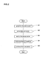
- Fig. 2 is a flowchart of an example of the simulating method according to the present invention.
- the computer first, the computer generates a chamber model 5 which is a finite volume model of the wall and the internal 3D space of the chamber 4.
- Fig. 3 is a perspective view of the chamber model 5.
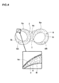
- Fig. 4 is a cross sectional view thereof.
- the chamber model 5 has a three-dimensional space enclosed by an outside circumference surface 50 defined by the interior surface of the casing 2, an inside circumferential surface 5i defined by the outer circumference surfaces of the two rotating rotors 3, and two end surfaces 5s on both sides of the rotors 3 in the axial direction.
- This three-dimensional closed space is divided (discretized) into the three-dimensional elements (e) such as tetrahedral elements, hexahedral elements and polyhedral elements.
- the plastic material material model
- pressure, temperature and/or velocity are computed.
- the outside circumference surface 5o and the two end surfaces 5s are not moved. However, the inside circumferential surface 5i is moved according to the rotation of the rotors 3, and accordingly, the configuration of the chamber model 5 is changed.
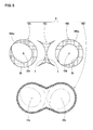
- the chamber model 5 is composed of four functional parts: a pair of rotative parts 5A and 5B; an in-between part 5C sandwiched therebetween; and an outer frame part 5D surrounding these parts 5A, 5B and 5C.
- Each rotative part 5A/5B is tubular and has a cylindrical circumference surface 5Ao/5Bo and an inside circumferential surface 5i corresponding to the circumference surface of one rotor 3.
- the rotative parts 5A and 5B are placed in the outer frame part 5D and defined as rotatable around the respective center axes 0a and 0b to represent the change in the configuration of the volume of the chamber caused by the rotations of the rotors 3.
- the in-between part 5C remains at rest between the rotative parts 5A and 5B, and has two concave surfaces j abutting on the respective rotative parts 5A and 5B.
- boundary conditions as sliding surface are defined on the concave surfaces j and the respective cylindrical circumference surfaces 5Ao and 5Bo.
- the outer frame part 5D is tubular and surrounds the rotative parts 5A and 5B and the in-between part 5C. Both of the axial ends thereof are closed by the two end surfaces 5s.
- boundary conditions as sliding surface are defined.
- the outer frame part 5D is subjected to a relatively large shearing force by the operation of the rotors. Therefore, in order to calculate the velocity and the like of the material in more detail, the elements constituting the outer frame part 5D are made smaller in size than those of the rotative parts 5A and 5B and the in-between part 5C. Thereby, velocity profile and the like of the material model near the interior surface of the chamber model 5 can be calculated in more detail.
- the material model is defined by the computer and stored.
- the material model is a model of the plastic material flowing or moving in the chamber 4.
- the plastic material in this embodiment is a rubber mixture in a plasticized state, therefore, physical properties of such rubber mixture are entered and stored in advance.
- viscoelastic properties (G' and G") of the plastic material are measured under plural temperature conditions. Then, according to the Cox-Merz rule, the measured viscoelastic properties are converted into the shear viscosity.
- the specific heat of the analysis object can be obtained by the thermally-insulated continuous-heating method (@ 25 degrees C), and the measured specific heat value is entered and stored in the computer in advance.
- the thermal conductivity of the analysis object can be obtained by the hot wire method (@ 25 degrees C), and the measured value is entered and stored in the computer in advance.
- the gas-phase model is a model of gas existing in the chamber.
- the filling rate of the plastic model in the chamber is less than 100 %, therefore, in order to enable flow calculations, the part not filled with the plastic model, is filled with the gas-phase model.
- the gas-phase model in this example is provided with viscosity and specific gravity.
- the specific gravity of the gas-phase model is set at the actual value of the specific gravity of the gas.
- the viscosity of the gas-phase model is set at a value more than the actual value of the viscosity of the gas by the computer.
- the filling rate of the plastic material in the chamber is less than 100 %, it is necessary to perform a flow calculation for a multiphase flow of the plastic material and the gas.
- the viscosity of the gas-phase model is increased as much as possible within a range which does not impact negatively on the calculated results.
- the viscosity of the gas-phase model is set in a range of from 5 to 10 times the actual viscosity of the gas.
- boundary conditions may include flow velocity boundary conditions and temperature boundary conditions at the surface of the chamber model 5.
- the flow velocity of the plastic model at the surface of the chamber model 5 may have non-zero values as well as zero value.
- the following expression (2) (Navier's Law) can be applied to slip phenomena at the interface between the material model and the chamber model 5.
- the velocity field in initial stage is obtained, then from the velocity field (or corrected velocity field), the shear stress of the material model at the surface of the chamber model 5 is obtained, then the slip velocity of the material model at the surface of the chamber model 5 is obtained by the above-mentioned expression (2).
- the wall-surface slip velocity of each surface of the chamber model 5 is gradually converged to the true value during the loop of the conventional SIMPLE algorithm, by multiplying the slip velocity by a relaxation coefficient less than 1.
- the conditions may include the initial temperature of the plastic model (in this embodiment 20 degrees C (293K)), the number of rotations of the rotors presented by the number of rotations of the rotative parts 5A and 5B, the slip ratio of the surface of the chamber model 5, the filling rate of the plastic model with respect to the volume of the chamber model 5 and the like.
- the conditions may include an initial state of the flow calculation, time intervals for calculations, the number of iterations in the internal processing, the maximum period of computation and the like.
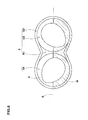
- the domain A on the upper side of a horizontal interface S defined as extending across the chamber model 5 is of the gas-phase model
- the domain M on the under side of the horizontal interface S is of the material model
- the filling rate of the plastic material (material model) can be adjusted.
- These conditions may be defined arbitrary according to an objective of the simulation.
- the material model and the gas-phase model are defined in the chamber model 5, and a flow calculation is made based on the above-mentioned conditions.
- the flow calculation in this embodiment is performed by the use of the Navier-stoks equation for an incompressibility flow, setting the density of each of the material model and the gas-phase model at a constant value.
- the material model is treated as fluid throughout the possible temperature range. Therefore, a Navier-stoks equation, an equation for conservation of mass and an energy equation have to be solved as simultaneous equations of fluid.
- the VOF (volume of Fluid) method which is used to calculate the flow of a free interface.
- the VOF method is not to directly calculate the motion of the interface between two kinds of fluid.
- a free interface is expressed by defining a filling rate (volume fraction) of each fluid within the volume of each element.
- a two-phase flow in which the gas-phase model and the material model flow together in the chamber model 5 is treated as a single phase flow.
- the motion equation to be solved is the following expression (3) in the three coordinate axes directions x, y and z. This becomes possible as a result of that the two phases are averaged by the VOF method and treated as a single phase.
- the computer can calculate the flow field as a shingle phase despite the multiphase.
- to be solved is the flow in which the materials properties are varied with position (volume fraction).
- the position of each phase can be estimated according to the distribution of the volume fraction obtained as the result of the calculation.
- the temperature of the material model can be obtained by the following energy equation (5).
- the distribution of the volume fraction determines the position of the interface between the two phases (or the gas-phase model and material model).
- each of the above-mentioned equations is solved by the pressure-based partitioned method.
- SIMPLE Semi-Implicit Method for Pressure-Linked Equations
- Fig. 7 shows a flowchart of an example of the flow calculation performed by the computer.
- the motion equation is defined by discretization of the current pressure field, and the motion equation is solved by a method of iteration. That is, the velocity of the material model (or multiphase) in three coordinate axes directions is computed.
- the method of iteration the Gauss-Seidel method can be used.
- uncorrected mass flow of the material model at the surfaces of the elements of the chamber model 5 is calculated first.
- the "uncorrected mass flow” is a mass flow temporarily used at the beginning of the loop of the SIMPLE algorithm. Such mass flow may have a large error, therefore, it is called “uncorrected mass flow”.
- the mass flow is necessary for determining whether the law of conservation of mass is satisfied or not.
- the boundary conditions of the interface are corrected (or updated). Specifically, from the corrected pressure field, the pressure gradient is obtained. The obtained pressure gradient is provided as the boundary conditions.
- v slip ⁇ w F slip + v wall
- step S62 If judged as being converged (Y in step S62), the time step is incremented by one to put a clock forward by one time interval.
- the convergence can be judged, based on whether the total number of the corrected mass flows is within a predetermined error range or not.
- step S64 If the clock is not reached to the predetermined time (N in step S64), then the computer again performs the step S51 and subsequent steps.
- step S62 if it is judged as being not converged, then the computer again performs the step S51 and subsequent steps.
- the shear heating of the material model is calculated, but the shear heating of the gas-phase model is not calculated.
- the shear velocity of the material model is relatively large, therefore, the shear heating needs to be calculated. The shear velocity often becomes increased at the interface between the material model and the gas-phase model.
- the shear heating is proportional to the shear viscosity multiplied by the square of the shear velocity, therefore, there is a possibility that an abnormally large value of the shear velocity adversely affects the calculation of the temperature (energy equation).
- the calculation of the shear heating is limited to only the material model.
- the calculation is performed with respect to only some of the elements of the chamber model 5 in which the value of the volume fraction ⁇ q of the material model is not less than a constant value (in this embodiment, 0.90).
- the wall-surface slip condition is defined on the interface between the surfaces of the material model and the chamber model 5.
- the slip velocity is given to the material model little by little as follows.
- the motion equation defined based on the current pressure field is solved by the computer to obtain the shear stress. From the obtained shear stress, the wall-surface slip velocity v slip to be set is calculated by the use of the expression (7) (the above-mentioned step S61).
- a relaxation coefficient ⁇ is provided, and the slip velocity is gradually increased up to the target value by changing the relaxation coefficient ⁇ .
- the computer performs the coupling of the pressure field and the velocity field to which the calculated slip velocity v slip is given, and the pressure-correction equation for correcting the pressure field is generated (the above-mentioned step S52).
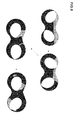
- Fig. 8 shows a temporal alteration of the state of the kneaded plastic material obtained through a kneading simulation which was made, starting from the initial state shown in Fig. 6 , by the method according to the present invention.
- the solid black part indicates the plastic material.
- the kneaded states of a plastic material can be accurately simulated, and the simulation results can be output visually.
Landscapes
- Engineering & Computer Science (AREA)
- Mechanical Engineering (AREA)
- Physics & Mathematics (AREA)
- Theoretical Computer Science (AREA)
- Computer Hardware Design (AREA)
- Evolutionary Computation (AREA)
- Geometry (AREA)
- General Engineering & Computer Science (AREA)
- General Physics & Mathematics (AREA)
- Processing And Handling Of Plastics And Other Materials For Molding In General (AREA)
Abstract
Description
- The present invention relates to a computerized method for simulating a multiphase flow of a plastic material and a gas, which is helpful to analyze fluidized states of a plastic material such as uncured rubber, resin and the like kneaded in a chamber.
- In recent years, various computerized simulation methods have been proposed. For example, the following
non-patent document 1 proposed a method to compute fluidized states of a plastic material such as uncured rubber or resin before cross-linked when kneaded in a banbury mixer. - [non-patent document 1] "Numerical and Experimental Study of Dispersive Mixing of Agglomerates", V. Collin (1)*, E. Peuvrel-Disdier (1) et al.
- The method of the
non-patent document 1 is premised on that the chamber is completely filled with the plastic material (namely, filling rate = 100 %). - However, it is extraordinary to make kneading with the filling rate of 100 % by the use of the banbury mixer or the like, and it has been known that with the change in the filling rate, the quality and state of the kneaded plastic material are altered.
- Despite these facts, the method of the
non-patent document 1 can not be performed by setting the filling rate of the plastic material at different values than 100 %. Indeed, it is almost impossible to make the kneading with the filling rate of 100 %, therefore, the simulation results of thenon-patent document 1 can not be verified through experiments. - On the other hand, the viscosity of a plastic material is largely different from the viscosity of air, therefore, if a two-phase of a plastic material and air in a chamber is simulated by making a flow calculation, the calculation tends to become unstable. In the case that the flow calculation is made by the use of the actual viscosity of the air, even if the calculation is completed without being interrupted, the computational time becomes very long and a high computational cost is required.
- Therefore, the present invention was studied out to solve the above-mentioned problems, and an object of the present invention is to provide a computerized method for simulating a multiphase flow of a plastic material and a gas residing in a chamber, in which the multiphase flow calculation can be made stably at various filling rates without largely increasing the computational time and thereby accurate simulations are possible.
- According to the present invention, a computerized method for simulating a fluidized state of a plastic material in a chamber, comprises
a step of generating a chamber model which is a finite volume model of the chamber,
a step of defining a material model of the plastic material,
a step defining a gas-phase model of gas,
a step of making a flow calculation of the material model and the gas-phase model which are in the chamber model, wherein
the material model is provided with viscosity of the plastic material, and
the gas-phase model is provided with viscosity which is more than the actual viscosity of the gas. - The chamber may be a kneading space of a banbury mixer in which at least one rotor is provided, and the plastic material may be an uncured rubber or resin material to be kneaded.
- In the flow calculation, it is preferred that a calculation of shear heating of the material model is performed, but a calculation of shear heating of the gas-phase model is not performed.
- On the interface between the plastic material model the chamber model, slip boundary conditions may be defined.
-
-
Fig. 1 is a schematic cross sectional view of a part of a banbury mixer for kneading a plastic material. -
Fig. 2 is a flow chart of an example of the method according to the present invention. -
Fig. 3 is a perspective view of a chamber model. -
Fig. 4 is a cross sectional view for explaining the meshing of the walls and internal space of the chamber model. -
Fig. 5 is a cross sectional view showing functional parts of the chamber model separately. -
Fig. 6 is a cross sectional view showing a state of the chamber model in which a material model and a gas-phase model are arranged. -
Fig. 7 is a flow chart of a procedure of the flow calculation. -
Fig. 8 is a diagram showing kneaded states of the plastic material obtained by the simulating method according to the present invention. - Embodiments of the present invention will now be described in detail in conjunction with accompanying drawings.
- The present invention is directed to a simulating method for estimating fluidized states of a plastic material disposed in a chamber by the use of a computer (not shown).
- The plastic material has viscosity like uncured rubber, resin or elastomer before cross-linked. However, it is not limited to these material. The plastic material may be any material as far as it has a stable fluidized state. In the case of uncured rubber before cross-linked, a state of the mixture kneaded in good part at around 80 degrees C may be regarded as a stable fluidized state.
- The chamber is a substantially closed space in which the plastic material is disposed and moved. The chamber may have any configuration. A typical example of the chamber is a kneading space of a banbury mixer. As shown in
Fig. 1 , thechamber 4 in this embodiment is formed between thecasing 2 of thebanbury mixer 1 and a pair ofrotors 3 disposed in thecasing 2 and has a sectional shape like a figure eight. The chamber is however, not limited to such configuration. -
Fig. 2 is a flowchart of an example of the simulating method according to the present invention. - In this embodiment, first, the computer generates a
chamber model 5 which is a finite volume model of the wall and the internal 3D space of thechamber 4. -
Fig. 3 is a perspective view of thechamber model 5. -
Fig. 4 is a cross sectional view thereof. - The
chamber model 5 has a three-dimensional space enclosed by anoutside circumference surface 50 defined by the interior surface of thecasing 2, an insidecircumferential surface 5i defined by the outer circumference surfaces of the tworotating rotors 3, and twoend surfaces 5s on both sides of therotors 3 in the axial direction. - This three-dimensional closed space is divided (discretized) into the three-dimensional elements (e) such as tetrahedral elements, hexahedral elements and polyhedral elements. For each element, physical quantities of the plastic material (material model) such as pressure, temperature and/or velocity are computed.
- The outside circumference surface 5o and the two
end surfaces 5s are not moved. However, the insidecircumferential surface 5i is moved according to the rotation of therotors 3, and accordingly, the configuration of thechamber model 5 is changed. - In the example shown in
Fig. 5 , thechamber model 5 is composed of four functional parts: a pair ofrotative parts part 5C sandwiched therebetween; and anouter frame part 5D surrounding theseparts - Each
rotative part 5A/5B is tubular and has a cylindrical circumference surface 5Ao/5Bo and an insidecircumferential surface 5i corresponding to the circumference surface of onerotor 3. - The
rotative parts outer frame part 5D and defined as rotatable around the respective center axes 0a and 0b to represent the change in the configuration of the volume of the chamber caused by the rotations of therotors 3. - In contrast, the in-between
part 5C remains at rest between therotative parts rotative parts - This allows physical actions (force, heat, etc.) occurring in the
rotative parts part 5C through the concave surfaces j. - The
outer frame part 5D is tubular and surrounds therotative parts part 5C. Both of the axial ends thereof are closed by the twoend surfaces 5s. - On the interface between the
outer frame part 5D and therotative parts outer frame part 5D and the in-betweenpart 5C, boundary conditions as sliding surface are defined. - This allows physical actions (force, heat, etc.) occurring in the
rotative parts outer frame part 5D through the interfaces therebetween. - The
outer frame part 5D is subjected to a relatively large shearing force by the operation of the rotors. Therefore, in order to calculate the velocity and the like of the material in more detail, the elements constituting theouter frame part 5D are made smaller in size than those of therotative parts part 5C. Thereby, velocity profile and the like of the material model near the interior surface of thechamber model 5 can be calculated in more detail. - Next, the material model is defined by the computer and stored. The material model is a model of the plastic material flowing or moving in the
chamber 4. - On the material model, physical properties of the plastic material such as shear viscosity, specific heat, thermal conductivity and specific gravity are defined and stored in the computer.
- As described above, the plastic material in this embodiment is a rubber mixture in a plasticized state, therefore, physical properties of such rubber mixture are entered and stored in advance.
- In order to obtain the shear viscosity, firstly, viscoelastic properties (G' and G") of the plastic material are measured under plural temperature conditions. Then, according to the Cox-Merz rule, the measured viscoelastic properties are converted into the shear viscosity.
- The shear viscosity obtained as above is approximated by the following expression (1) according to a power law.

wherein, - η: shear viscosity,
- m: a coefficient as a function of absolute temperature,
- γ': a shear velocity, and
- n: a coefficient.
- The specific heat of the analysis object (plastic material) can be obtained by the thermally-insulated continuous-heating method (@ 25 degrees C), and the measured specific heat value is entered and stored in the computer in advance.
- The thermal conductivity of the analysis object (plastic material) can be obtained by the hot wire method (@ 25 degrees C), and the measured value is entered and stored in the computer in advance.
- Next, a gas-phase model is defined by the computer and stored. The gas-phase model is a model of gas existing in the chamber.
- In the present invention, the filling rate of the plastic model in the chamber is less than 100 %, therefore, in order to enable flow calculations, the part not filled with the plastic model, is filled with the gas-phase model.
- The gas-phase model in this example is provided with viscosity and specific gravity.
- The specific gravity of the gas-phase model is set at the actual value of the specific gravity of the gas.
- However, The viscosity of the gas-phase model is set at a value more than the actual value of the viscosity of the gas by the computer.
- When the filling rate of the plastic material in the chamber is less than 100 %, it is necessary to perform a flow calculation for a multiphase flow of the plastic material and the gas.
- Usually, a difference in the viscosity between a gas and a plastic material is very large. Therefore, if the calculation is made taking the shear heating due to the velocity into consideration, the shear heating is extraordinarily increased at the interface between the gas-phase model and the material model, and as a result, the calculation is liable to become unstable.
- According to the present invention, therefore, in order to make the calculation stable, the viscosity of the gas-phase model is increased as much as possible within a range which does not impact negatively on the calculated results. As a result, it becomes possible to increase the time intervals (time increment) in the simulation to speed up the computation.
- Changing the viscosity of the gas-phase model only, simulations were made by the present inventors in order to compare the pressure field in the
chamber model 5. As a result, it was found that, if the viscosity of the gas-phase model exceeds 10 times the actual viscosity, then the pressure in thechamber model 5 becomes increased and adversely affects the pressure field. - However, if the viscosity of the gas-phase model is less than 5 times the actual viscosity, then it becomes difficult to make the calculation stable.
- Therefore, it is preferable that the viscosity of the gas-phase model is set in a range of from 5 to 10 times the actual viscosity of the gas.
- Next, various conditions including boundary conditions necessary for the flow calculation are defined. The boundary conditions may include flow velocity boundary conditions and temperature boundary conditions at the surface of the
chamber model 5. - As to the flow velocity boundary conditions,
- (a) wall-surface non-slip condition, or
- (b) wall-surface slip condition
- In the case of the wall-surface non-slip condition, the flow velocity of the material model at the surface of the
chamber model 5 is always zero. - In the case of the wall-surface slip condition, the flow velocity of the plastic model at the surface of the
chamber model 5 may have non-zero values as well as zero value. In this case, the following expression (2) (Navier's Law) can be applied to slip phenomena at the interface between the material model and thechamber model 5.

wherein - fS: shear stress of the material model at the surface of the
chamber model 5, - vSlip: slip velocity (tangent velocity) of the material model at the surface of the
chamber model 5, - vwall: tangent velocity of the material model at the surface of the
chamber model 5, - Fslip, eslip: materials properties (if eslip=1 then linear: if 0<eslip<1 then power law).
- In order to define the slip velocity vslip of the material model at the surface of the
chamber model 5, firstly, the velocity field in initial stage is obtained, then from the velocity field (or corrected velocity field), the shear stress of the material model at the surface of thechamber model 5 is obtained, then the slip velocity of the material model at the surface of thechamber model 5 is obtained by the above-mentioned expression (2). - On this occasion, if needed, in order to control an abrupt increase in the slip velocity, it is preferred that the wall-surface slip velocity of each surface of the
chamber model 5 is gradually converged to the true value during the loop of the conventional SIMPLE algorithm, by multiplying the slip velocity by a relaxation coefficient less than 1. (after-mentioned) - As to the temperature boundary conditions,
- (a) thermally insulated condition in which the heat does not escape outside from the
chamber model 5 through the surface thereof, or - (b) condition in which the entire surface of the
chamber model 5 has a constant temperature (for example 50 degrees C) may be defined. - Further, the conditions may include the initial temperature of the plastic model (in this embodiment 20 degrees C (293K)), the number of rotations of the rotors presented by the number of rotations of the
rotative parts chamber model 5, the filling rate of the plastic model with respect to the volume of thechamber model 5 and the like. - Furthermore, the conditions may include an initial state of the flow calculation, time intervals for calculations, the number of iterations in the internal processing, the maximum period of computation and the like.
- As to the initial state, for example as shown in
Fig. 6 , it is possible to define such that
the domain A on the upper side of a horizontal interface S defined as extending across thechamber model 5 is of the gas-phase model, and
the domain M on the under side of the horizontal interface S is of the material model. - Therefore, by changing the level of this interface S, the filling rate of the plastic material (material model) can be adjusted. These conditions may be defined arbitrary according to an objective of the simulation.
- Next, the material model and the gas-phase model are defined in the
chamber model 5, and a flow calculation is made based on the above-mentioned conditions. - In the flow calculation, velocity components in three coordinate axes directions (x, y, z) which specify the motional state of the material model, and
the temperature T and the pressure p which specify the internal state of the material model are computed. Thus, unknowns to be solved are these five physical quantities. - The flow calculation in this embodiment is performed by the use of the Navier-stoks equation for an incompressibility flow, setting the density of each of the material model and the gas-phase model at a constant value.
- In this embodiment, the material model is treated as fluid throughout the possible temperature range. Therefore, a Navier-stoks equation, an equation for conservation of mass and an energy equation have to be solved as simultaneous equations of fluid.
- In this embodiment, in order to deal with a multiphase flow of the gas and plastic material, the VOF (volume of Fluid) method, which is used to calculate the flow of a free interface, is employed. The VOF method is not to directly calculate the motion of the interface between two kinds of fluid. In the VOF method, a free interface is expressed by defining a filling rate (volume fraction) of each fluid within the volume of each element.
- The government equations are is as follows.
- In the this embodiment, a two-phase flow in which the gas-phase model and the material model flow together in the
chamber model 5 is treated as a single phase flow. In this case, the motion equation to be solved is the following expression (3) in the three coordinate axes directions x, y and z. This becomes possible as a result of that the two phases are averaged by the VOF method and treated as a single phase.
wherein - u: velocity of the multiphase flow model,
- p: pressure of multiphase flow model,
- p: density of the multiphase flow model,
- g: gravitational acceleration,
- T: absolute temperature of the multiphase flow model,
- F: external force.
- The values of the density ρ and coefficient of viscosity µ in the vicinity of the interface between the material model and the gas-phase model which are used herein, are weighted by the occupied volumes of the respective phases, namely the material model and gas-phase model and then averaged as shown in the following expression (4).

wherein n - αq: volume fraction of each phase in each element
- ρq density of each phase in each element
- µq: viscosity of each phase in each element
- As to the equation for conservation of mass (equation of continuity) and pressure equation, it is enough to solve only one set of equations in the three coordinate axes directions. Therefore, according to the simulating method in this embodiment, the computer can calculate the flow field as a shingle phase despite the multiphase. In other words, to be solved is the flow in which the materials properties are varied with position (volume fraction).
- The position of each phase can be estimated according to the distribution of the volume fraction obtained as the result of the calculation.
- The temperature of the material model can be obtained by the following energy equation (5).


wherein - E: enthalpy,
- k: thermal conductivity,
- S: source term.
- The distribution of the volume fraction determines the position of the interface between the two phases (or the gas-phase model and material model).
- The volume fraction αq can be obtained by accurately solving the following expression (6).

- If the volume fraction αq=0 in an arbitrary element (e), this means that the q phase (q phase: material model) does not exist in this element (e).
- If the volume fraction αq=1, this means that the entire volume of the element (e) is filled with the q phase.
- If 0 < αq < 1, this means that the element (e) is filled with the q phase and other phase (gas-phase model), that is, the element is multiphase having an interface.
- This equation can be solved by Modified-HRIC (Implicit) of which detailed description is given by "ANSYS Fluent User's Manual, 26.2.9 Modified HRIC Scheme."
- In this embodiment, each of the above-mentioned equations is solved by the pressure-based partitioned method.
- For the coupling of the pressure equation and the motion equation, the SIMPLE (Semi-Implicit Method for Pressure-Linked Equations) algorithm is preferably used.
-
Fig. 7 shows a flowchart of an example of the flow calculation performed by the computer. - In this example, firstly, upper and lower limits for the pressure gradient and the velocity are set, and the velocity gradient and the pressure gradient are computed.
- Next, the motion equation is defined by discretization of the current pressure field, and the motion equation is solved by a method of iteration. That is, the velocity of the material model (or multiphase) in three coordinate axes directions is computed. As to the method of iteration, the Gauss-Seidel method can be used.
- Next, in order to examine whether or not the above-mentioned velocity satisfies the equation for conservation of mass, uncorrected mass flow of the material model at the surfaces of the elements of the
chamber model 5 is calculated first. Here, the "uncorrected mass flow" is a mass flow temporarily used at the beginning of the loop of the SIMPLE algorithm. Such mass flow may have a large error, therefore, it is called "uncorrected mass flow". - The mass flow is necessary for determining whether the law of conservation of mass is satisfied or not.
- Next, using the SIMPLE algorithm, the velocity field and the pressure field are coupled, and the following pressure-correction equation for correcting the pressure field is generated.

- Next, by the method of iteration for example AMG solver, CG or Bi-CG and the like, the pressure-correction equation is solved, and a pressure correction amount p' is computed.
- Next, based on the obtained solution, the pressure field is corrected by the following expression:

wherein - p : pressure,
- n : current number of time step
- ω : relaxation coefficient which is 0.3 in this example.
- Next, the boundary conditions of the interface are corrected (or updated). Specifically, from the corrected pressure field, the pressure gradient is obtained. The obtained pressure gradient is provided as the boundary conditions.
- Next, the mass flow of at the surfaces of the elements is corrected by the following expression:

wherein, - mfn+1 : corrected mass flow at the surfaces of the elements,
- mf*: uncorrected mass flow at the surfaces of the elements,
- m'f: correcting value of mass flow.
- Next, the velocity field is corrected by the following expression:

wherein - V: volume of element,
- v*: intermediary velocity field before corrected, obtained from motion equation,
- ∇p': gradient of pressure correction amount,
- ∂pV: diagonal component of matrix of motion equation,
- Next, by solving the above-mentioned energy equation (5), the temperature and viscosity of the material model are calculated.
- Further, the slip velocity v Slip of the wall-surface of the
chamber model 5 is calculated by the following expression (7).
wherein, - τ w : wall-surface shear stress,
- vslip: the slip velocity of the material model at the surface of the
chamber model 5, - vwall: the tangent velocity of the material model at the surface of the
chamber model 5, - Fslip: materials properties (coefficient) expressing the tendency to slip. If the value becomes increased, it becomes the wall-surface non-slip condition.
- Next, it is judged if the solution of this calculation is converged. The criteria of the judgment for convergence are defined beforehand.
- If judged as being converged (Y in step S62), the time step is incremented by one to put a clock forward by one time interval.
- The convergence can be judged, based on whether the total number of the corrected mass flows is within a predetermined error range or not.
- If the clock is not reached to the predetermined time (N in step S64), then the computer again performs the step S51 and subsequent steps.
- On the other hand, in the step S62, if it is judged as being not converged, then the computer again performs the step S51 and subsequent steps.
- In the flow calculations in this embodiment, the shear heating of the material model is calculated, but the shear heating of the gas-phase model is not calculated. The shear velocity of the material model is relatively large, therefore, the shear heating needs to be calculated. The shear velocity often becomes increased at the interface between the material model and the gas-phase model.
- The shear heating is proportional to the shear viscosity multiplied by the square of the shear velocity, therefore, there is a possibility that an abnormally large value of the shear velocity adversely affects the calculation of the temperature (energy equation).
- Therefore, in this embodiment, the calculation of the shear heating is limited to only the material model.
- More specifically, the calculation is performed with respect to only some of the elements of the
chamber model 5 in which the value of the volume fraction αq of the material model is not less than a constant value (in this embodiment, 0.90). - In this embodiment, the wall-surface slip condition is defined on the interface between the surfaces of the material model and the
chamber model 5. - In this embodiment, the slip velocity is given to the material model little by little as follows.
- The motion equation defined based on the current pressure field is solved by the computer to obtain the shear stress. From the obtained shear stress, the wall-surface slip velocity vslip to be set is calculated by the use of the expression (7) (the above-mentioned step S61).
- In the next step, if the calculated slip velocity vslip is given to the interface as it is, there is a possibility that the wall-surface shear stress τw given by the expression (2)' becomes an abnormal value, and thereby an abnormal slip velocity is defined on the wall-surface.
- Therefore, it is desirable that, as shown in the following expression (8), a relaxation coefficient β is provided, and the slip velocity is gradually increased up to the target value by changing the relaxation coefficient β.

wherein - 0<β<1,
- n: number of repetitions of calculation.
- Then, by the use of the SIMPLE algorithm or the like, the computer performs the coupling of the pressure field and the velocity field to which the calculated slip velocity vslip is given, and the pressure-correction equation for correcting the pressure field is generated (the above-mentioned step S52).
- In order to confirm the effects of the present invention, flow simulations of plastic material were made based on the chamber model shown in
Fig. 3 and conditions shown in Table 1. with respect to the distribution, dispersion and temperature of the kneaded material and the rotors' torque, the computational accuracy was evaluated into three ranks, whereinrank 1 means good, and ran 3 means bad. The results are shown in Table 1.Table 1 Ref. Ex.1 Ex.2 Ex.3 time intervals (msec) 1.973 1.973 1.973 1.973 plastic material filling rate 70% 70 % 70% 70% gas-phase model viscosity (Pa·s) 1.79E-05 8.95E-05 1.79E-04 1.89E-04 (times actual viscosity) 1.00 5.00 10.00 10.56 calculated shear heating only material model only material model only material model only material model wall-surface slip Fslip 6.0E+5 6.0E+5 6.0E+5 6.0E+5 distribution 3 1 1 1 dispersion 3 1 1 1 rotors torque 3 1 1 3 plastic material temperature 3 1 1 1 computational time 2 weeks 2 weeks 2 weeks 2 weeks - From the test results, it was confirmed that according to the present invention, the computational accuracy is remarkably improved while maintaining the computational time.
-
Fig. 8 shows a temporal alteration of the state of the kneaded plastic material obtained through a kneading simulation which was made, starting from the initial state shown inFig. 6 , by the method according to the present invention. InFig. 8 , the solid black part indicates the plastic material. - As explained, according to this embodiment, the kneaded states of a plastic material can be accurately simulated, and the simulation results can be output visually.
Claims (4)
- A computerized method for simulating a fluidized state of a plastic material in a chamber, comprising
a step of generating a chamber model which is a finite volume model of the chamber,
a step of defining a material model of the plastic material,
a step defining a gas-phase model of gas,
a step of making a flow calculation of the material model and the gas-phase model which are in the chamber model, wherein
the material model is provided with viscosity of the plastic material, and
the gas-phase model is provided with viscosity which is more than the actual viscosity of the gas. - The computerized method according to claim 1, wherein
the chamber is a kneading space of a banbury mixer in which at least one rotor is provided, and
the plastic material is an uncured rubber or resin material to be kneaded. - The computerized method according to claim 1 or 2, wherein
in the flow calculation, a calculation of shear heating of the material model is performed but a calculation of shear heating of the gas-phase model is not performed. - The computerized method according to claim 1, 2 or 3, wherein
slip boundary conditions are defined on the interface between the plastic material model the chamber model.
Applications Claiming Priority (1)
| Application Number | Priority Date | Filing Date | Title |
|---|---|---|---|
| JP2012011317A JP5514236B2 (en) | 2012-01-23 | 2012-01-23 | Method for simulating plastic materials |
Publications (2)
| Publication Number | Publication Date |
|---|---|
| EP2618281A2 true EP2618281A2 (en) | 2013-07-24 |
| EP2618281A3 EP2618281A3 (en) | 2017-07-05 |
Family
ID=47563016
Family Applications (1)
| Application Number | Title | Priority Date | Filing Date |
|---|---|---|---|
| EP12196470.4A Withdrawn EP2618281A3 (en) | 2012-01-23 | 2012-12-11 | Method for simulating multiphase flow of plastic material and gas |
Country Status (5)
| Country | Link |
|---|---|
| US (1) | US9193093B2 (en) |
| EP (1) | EP2618281A3 (en) |
| JP (1) | JP5514236B2 (en) |
| KR (1) | KR20130086178A (en) |
| CN (1) | CN103218471B (en) |
Families Citing this family (10)
| Publication number | Priority date | Publication date | Assignee | Title |
|---|---|---|---|---|
| JP5564074B2 (en) * | 2012-06-11 | 2014-07-30 | 住友ゴム工業株式会社 | Fluid simulation method |
| JP6405160B2 (en) * | 2014-09-01 | 2018-10-17 | 住友ゴム工業株式会社 | Analysis method of kneading state of viscous fluid |
| JP6092832B2 (en) * | 2014-10-21 | 2017-03-08 | 株式会社日本製鋼所 | Fluid behavior prediction apparatus, fluid behavior prediction method and fluid behavior prediction program |
| JP6593009B2 (en) * | 2015-07-27 | 2019-10-23 | 住友ゴム工業株式会社 | Analysis method of kneading state of viscous fluid |
| JP6527434B2 (en) * | 2015-09-17 | 2019-06-05 | 住友ゴム工業株式会社 | Analysis method of kneading state of viscous fluid |
| JP6733183B2 (en) * | 2016-01-14 | 2020-07-29 | 住友ゴム工業株式会社 | Analysis method of kneading state of viscous fluid |
| JP6885137B2 (en) * | 2017-03-27 | 2021-06-09 | 住友ゴム工業株式会社 | Analysis method of kneading state of viscous fluid |
| JP7119471B2 (en) * | 2018-03-20 | 2022-08-17 | 住友ゴム工業株式会社 | Fluid simulation method |
| FR3087387B1 (en) * | 2018-10-19 | 2021-10-08 | Michelin & Cie | PROCESS FOR SIMULATION OF THE TIME EVOLUTION OF A PHYSICAL SYSTEM IN REAL TIME |
| CN121480385A (en) * | 2025-12-09 | 2026-02-06 | 西安交通大学 | A simulation method, apparatus, medium, and device for underfilling of flip chips. |
Family Cites Families (11)
| Publication number | Priority date | Publication date | Assignee | Title |
|---|---|---|---|---|
| JP3566009B2 (en) * | 1996-12-27 | 2004-09-15 | 松下電器産業株式会社 | Particle type fluid simulation method and apparatus |
| EP0919941B1 (en) * | 1997-11-25 | 2005-09-21 | Sumitomo Rubber Industries Limited | Method of and apparatus for simulating rolling tyre |
| ES2191623T3 (en) * | 1999-05-19 | 2003-09-16 | Exxonmobil Chem Patents Inc | MIXTURES OF ELASTOMEROS BASED ON ISOBUTILENE THAT HAVE IMPROVED RESISTANCE AND ELASTICITY AND REDUCED PERMEABILITY. |
| WO2001041994A1 (en) * | 1999-12-13 | 2001-06-14 | Alpha Technologies, U.S., L.P. | Method and apparatus for rubber manufacturing process |
| JP4195940B2 (en) * | 2003-03-31 | 2008-12-17 | 独立行政法人産業技術総合研究所 | Fluid analysis device |
| FR2905497B1 (en) * | 2006-09-01 | 2008-11-14 | Michelin Soc Tech | METHOD FOR SIMULATING THE THERMO-MECHANICAL BEHAVIOR OF A TIRE, AND APPLICATION |
| WO2009003677A1 (en) * | 2007-07-02 | 2009-01-08 | Magma Giessereitechnologie Gmbh | Method and apparatus for describing the statistical orientation distribution of particles in a simulation of a mould filling process |
| JP4871233B2 (en) * | 2007-08-21 | 2012-02-08 | 株式会社豊田中央研究所 | Melting material filling analysis method and filling analysis program thereof |
| JP2009110228A (en) * | 2007-10-30 | 2009-05-21 | Japan Science & Technology Agency | Molecular motion analysis method and analysis program for polymer compound in which solid particles are dispersed |
| US20110067800A1 (en) * | 2007-11-13 | 2011-03-24 | Pirelli Tyre S.P.A. | Process and plant for producing an elastomeric compound |
| CN101833604B (en) * | 2010-04-29 | 2012-11-14 | 浙江工业大学 | Soft abrasive flow ultra-precision machining two-phase flow monitoring method based on discrete phase model |
-
2012
- 2012-01-23 JP JP2012011317A patent/JP5514236B2/en active Active
- 2012-11-28 US US13/687,892 patent/US9193093B2/en not_active Expired - Fee Related
- 2012-12-11 EP EP12196470.4A patent/EP2618281A3/en not_active Withdrawn
-
2013
- 2013-01-18 CN CN201310018503.7A patent/CN103218471B/en not_active Expired - Fee Related
- 2013-01-22 KR KR1020130006858A patent/KR20130086178A/en not_active Abandoned
Non-Patent Citations (1)
| Title |
|---|
| V. COLLIN, NUMERICAL AND EXPERIMENTAL STUDY OF DISPERSIVE MIXING OF AGGLOMERATES |
Also Published As
| Publication number | Publication date |
|---|---|
| EP2618281A3 (en) | 2017-07-05 |
| JP2013147002A (en) | 2013-08-01 |
| CN103218471A (en) | 2013-07-24 |
| CN103218471B (en) | 2017-10-24 |
| JP5514236B2 (en) | 2014-06-04 |
| US20130188438A1 (en) | 2013-07-25 |
| US9193093B2 (en) | 2015-11-24 |
| KR20130086178A (en) | 2013-07-31 |
Similar Documents
| Publication | Publication Date | Title |
|---|---|---|
| US9193093B2 (en) | Method for simulating multiphase flow of plastic material and gas | |
| EP2674885B1 (en) | Method for simulating high-viscosity fluid | |
| US9378307B2 (en) | Method and apparatus for simulating plastic material flowing through extruding channel | |
| CN103294844B (en) | Analogy method for fluid kneaded state | |
| WO2021249897A1 (en) | Method for determining a coefficient in a thermoplastic polymer viscosity calculation | |
| JP6405160B2 (en) | Analysis method of kneading state of viscous fluid | |
| JP6306979B2 (en) | Method for simulation of extrusion of plastic material | |
| JP6885137B2 (en) | Analysis method of kneading state of viscous fluid | |
| JP6790721B2 (en) | Analysis method of kneading state of viscous fluid | |
| JP6733183B2 (en) | Analysis method of kneading state of viscous fluid | |
| JP6848754B2 (en) | Kneading simulation method for thermoplastic materials | |
| JP2019089229A (en) | Simulation method of viscoelastic material | |
| Sarghini | Analysis and Simulation of Pasta Dough Extrusion Process by CFD | |
| Roos Launchbury | Solver | |
| Syrakos et al. | Solution of viscoplastic flows with the finite volume/multigrid method |
Legal Events
| Date | Code | Title | Description |
|---|---|---|---|
| PUAI | Public reference made under article 153(3) epc to a published international application that has entered the european phase |
Free format text: ORIGINAL CODE: 0009012 |
|
| AK | Designated contracting states |
Kind code of ref document: A2 Designated state(s): AL AT BE BG CH CY CZ DE DK EE ES FI FR GB GR HR HU IE IS IT LI LT LU LV MC MK MT NL NO PL PT RO RS SE SI SK SM TR |
|
| AX | Request for extension of the european patent |
Extension state: BA ME |
|
| PUAL | Search report despatched |
Free format text: ORIGINAL CODE: 0009013 |
|
| AK | Designated contracting states |
Kind code of ref document: A3 Designated state(s): AL AT BE BG CH CY CZ DE DK EE ES FI FR GB GR HR HU IE IS IT LI LT LU LV MC MK MT NL NO PL PT RO RS SE SI SK SM TR |
|
| AX | Request for extension of the european patent |
Extension state: BA ME |
|
| RIC1 | Information provided on ipc code assigned before grant |
Ipc: G06F 17/50 20060101AFI20170529BHEP Ipc: B29B 7/00 20060101ALI20170529BHEP |
|
| STAA | Information on the status of an ep patent application or granted ep patent |
Free format text: STATUS: REQUEST FOR EXAMINATION WAS MADE |
|
| 17P | Request for examination filed |
Effective date: 20171218 |
|
| RBV | Designated contracting states (corrected) |
Designated state(s): AL AT BE BG CH CY CZ DE DK EE ES FI FR GB GR HR HU IE IS IT LI LT LU LV MC MK MT NL NO PL PT RO RS SE SI SK SM TR |
|
| STAA | Information on the status of an ep patent application or granted ep patent |
Free format text: STATUS: THE APPLICATION HAS BEEN WITHDRAWN |
|
| 18W | Application withdrawn |
Effective date: 20191022 |