EP2618178A2 - Component inspection using a curved transducer array - Google Patents
Component inspection using a curved transducer array Download PDFInfo
- Publication number
- EP2618178A2 EP2618178A2 EP20130150407 EP13150407A EP2618178A2 EP 2618178 A2 EP2618178 A2 EP 2618178A2 EP 20130150407 EP20130150407 EP 20130150407 EP 13150407 A EP13150407 A EP 13150407A EP 2618178 A2 EP2618178 A2 EP 2618178A2
- Authority
- EP
- European Patent Office
- Prior art keywords
- array
- wave
- curved
- focal law
- transducer
- Prior art date
- Legal status (The legal status is an assumption and is not a legal conclusion. Google has not performed a legal analysis and makes no representation as to the accuracy of the status listed.)
- Withdrawn
Links
- 238000007689 inspection Methods 0.000 title claims abstract description 28
- 238000000034 method Methods 0.000 claims abstract description 17
- 239000000523 sample Substances 0.000 claims description 21
- 238000003491 array Methods 0.000 description 4
- 230000007547 defect Effects 0.000 description 3
- 230000005540 biological transmission Effects 0.000 description 2
- 230000015572 biosynthetic process Effects 0.000 description 2
- 239000011800 void material Substances 0.000 description 2
- XLYOFNOQVPJJNP-UHFFFAOYSA-N water Substances O XLYOFNOQVPJJNP-UHFFFAOYSA-N 0.000 description 2
- 239000000463 material Substances 0.000 description 1
- 238000012986 modification Methods 0.000 description 1
- 230000004048 modification Effects 0.000 description 1
- 230000001902 propagating effect Effects 0.000 description 1
Images

Classifications
-
- G—PHYSICS
- G01—MEASURING; TESTING
- G01N—INVESTIGATING OR ANALYSING MATERIALS BY DETERMINING THEIR CHEMICAL OR PHYSICAL PROPERTIES
- G01N29/00—Investigating or analysing materials by the use of ultrasonic, sonic or infrasonic waves; Visualisation of the interior of objects by transmitting ultrasonic or sonic waves through the object
- G01N29/22—Details, e.g. general constructional or apparatus details
- G01N29/221—Arrangements for directing or focusing the acoustical waves
-
- G—PHYSICS
- G01—MEASURING; TESTING
- G01N—INVESTIGATING OR ANALYSING MATERIALS BY DETERMINING THEIR CHEMICAL OR PHYSICAL PROPERTIES
- G01N29/00—Investigating or analysing materials by the use of ultrasonic, sonic or infrasonic waves; Visualisation of the interior of objects by transmitting ultrasonic or sonic waves through the object
- G01N29/04—Analysing solids
- G01N29/043—Analysing solids in the interior, e.g. by shear waves
-
- G—PHYSICS
- G01—MEASURING; TESTING
- G01N—INVESTIGATING OR ANALYSING MATERIALS BY DETERMINING THEIR CHEMICAL OR PHYSICAL PROPERTIES
- G01N29/00—Investigating or analysing materials by the use of ultrasonic, sonic or infrasonic waves; Visualisation of the interior of objects by transmitting ultrasonic or sonic waves through the object
- G01N29/22—Details, e.g. general constructional or apparatus details
- G01N29/24—Probes
- G01N29/2456—Focusing probes
-
- G—PHYSICS
- G01—MEASURING; TESTING
- G01N—INVESTIGATING OR ANALYSING MATERIALS BY DETERMINING THEIR CHEMICAL OR PHYSICAL PROPERTIES
- G01N29/00—Investigating or analysing materials by the use of ultrasonic, sonic or infrasonic waves; Visualisation of the interior of objects by transmitting ultrasonic or sonic waves through the object
- G01N29/22—Details, e.g. general constructional or apparatus details
- G01N29/26—Arrangements for orientation or scanning by relative movement of the head and the sensor
- G01N29/262—Arrangements for orientation or scanning by relative movement of the head and the sensor by electronic orientation or focusing, e.g. with phased arrays
-
- G—PHYSICS
- G01—MEASURING; TESTING
- G01S—RADIO DIRECTION-FINDING; RADIO NAVIGATION; DETERMINING DISTANCE OR VELOCITY BY USE OF RADIO WAVES; LOCATING OR PRESENCE-DETECTING BY USE OF THE REFLECTION OR RERADIATION OF RADIO WAVES; ANALOGOUS ARRANGEMENTS USING OTHER WAVES
- G01S15/00—Systems using the reflection or reradiation of acoustic waves, e.g. sonar systems
- G01S15/88—Sonar systems specially adapted for specific applications
- G01S15/89—Sonar systems specially adapted for specific applications for mapping or imaging
- G01S15/8906—Short-range imaging systems; Acoustic microscope systems using pulse-echo techniques
- G01S15/8909—Short-range imaging systems; Acoustic microscope systems using pulse-echo techniques using a static transducer configuration
- G01S15/8915—Short-range imaging systems; Acoustic microscope systems using pulse-echo techniques using a static transducer configuration using a transducer array
- G01S15/892—Short-range imaging systems; Acoustic microscope systems using pulse-echo techniques using a static transducer configuration using a transducer array the array being curvilinear
-
- G—PHYSICS
- G01—MEASURING; TESTING
- G01S—RADIO DIRECTION-FINDING; RADIO NAVIGATION; DETERMINING DISTANCE OR VELOCITY BY USE OF RADIO WAVES; LOCATING OR PRESENCE-DETECTING BY USE OF THE REFLECTION OR RERADIATION OF RADIO WAVES; ANALOGOUS ARRANGEMENTS USING OTHER WAVES
- G01S15/00—Systems using the reflection or reradiation of acoustic waves, e.g. sonar systems
- G01S15/88—Sonar systems specially adapted for specific applications
- G01S15/89—Sonar systems specially adapted for specific applications for mapping or imaging
- G01S15/8906—Short-range imaging systems; Acoustic microscope systems using pulse-echo techniques
- G01S15/8909—Short-range imaging systems; Acoustic microscope systems using pulse-echo techniques using a static transducer configuration
- G01S15/8915—Short-range imaging systems; Acoustic microscope systems using pulse-echo techniques using a static transducer configuration using a transducer array
- G01S15/8922—Short-range imaging systems; Acoustic microscope systems using pulse-echo techniques using a static transducer configuration using a transducer array the array being concentric or annular
-
- G—PHYSICS
- G01—MEASURING; TESTING
- G01S—RADIO DIRECTION-FINDING; RADIO NAVIGATION; DETERMINING DISTANCE OR VELOCITY BY USE OF RADIO WAVES; LOCATING OR PRESENCE-DETECTING BY USE OF THE REFLECTION OR RERADIATION OF RADIO WAVES; ANALOGOUS ARRANGEMENTS USING OTHER WAVES
- G01S15/00—Systems using the reflection or reradiation of acoustic waves, e.g. sonar systems
- G01S15/88—Sonar systems specially adapted for specific applications
- G01S15/89—Sonar systems specially adapted for specific applications for mapping or imaging
- G01S15/8906—Short-range imaging systems; Acoustic microscope systems using pulse-echo techniques
- G01S15/8909—Short-range imaging systems; Acoustic microscope systems using pulse-echo techniques using a static transducer configuration
- G01S15/8915—Short-range imaging systems; Acoustic microscope systems using pulse-echo techniques using a static transducer configuration using a transducer array
- G01S15/8925—Short-range imaging systems; Acoustic microscope systems using pulse-echo techniques using a static transducer configuration using a transducer array the array being a two-dimensional transducer configuration, i.e. matrix or orthogonal linear arrays
-
- G—PHYSICS
- G01—MEASURING; TESTING
- G01S—RADIO DIRECTION-FINDING; RADIO NAVIGATION; DETERMINING DISTANCE OR VELOCITY BY USE OF RADIO WAVES; LOCATING OR PRESENCE-DETECTING BY USE OF THE REFLECTION OR RERADIATION OF RADIO WAVES; ANALOGOUS ARRANGEMENTS USING OTHER WAVES
- G01S15/00—Systems using the reflection or reradiation of acoustic waves, e.g. sonar systems
- G01S15/88—Sonar systems specially adapted for specific applications
- G01S15/89—Sonar systems specially adapted for specific applications for mapping or imaging
- G01S15/8906—Short-range imaging systems; Acoustic microscope systems using pulse-echo techniques
- G01S15/8909—Short-range imaging systems; Acoustic microscope systems using pulse-echo techniques using a static transducer configuration
- G01S15/8929—Short-range imaging systems; Acoustic microscope systems using pulse-echo techniques using a static transducer configuration using a three-dimensional transducer configuration
-
- G—PHYSICS
- G10—MUSICAL INSTRUMENTS; ACOUSTICS
- G10K—SOUND-PRODUCING DEVICES; METHODS OR DEVICES FOR PROTECTING AGAINST, OR FOR DAMPING, NOISE OR OTHER ACOUSTIC WAVES IN GENERAL; ACOUSTICS NOT OTHERWISE PROVIDED FOR
- G10K11/00—Methods or devices for transmitting, conducting or directing sound in general; Methods or devices for protecting against, or for damping, noise or other acoustic waves in general
- G10K11/18—Methods or devices for transmitting, conducting or directing sound
- G10K11/26—Sound-focusing or directing, e.g. scanning
- G10K11/32—Sound-focusing or directing, e.g. scanning characterised by the shape of the source
-
- G—PHYSICS
- G10—MUSICAL INSTRUMENTS; ACOUSTICS
- G10K—SOUND-PRODUCING DEVICES; METHODS OR DEVICES FOR PROTECTING AGAINST, OR FOR DAMPING, NOISE OR OTHER ACOUSTIC WAVES IN GENERAL; ACOUSTICS NOT OTHERWISE PROVIDED FOR
- G10K11/00—Methods or devices for transmitting, conducting or directing sound in general; Methods or devices for protecting against, or for damping, noise or other acoustic waves in general
- G10K11/18—Methods or devices for transmitting, conducting or directing sound
- G10K11/26—Sound-focusing or directing, e.g. scanning
- G10K11/34—Sound-focusing or directing, e.g. scanning using electrical steering of transducer arrays, e.g. beam steering
-
- G—PHYSICS
- G01—MEASURING; TESTING
- G01N—INVESTIGATING OR ANALYSING MATERIALS BY DETERMINING THEIR CHEMICAL OR PHYSICAL PROPERTIES
- G01N2291/00—Indexing codes associated with group G01N29/00
- G01N2291/10—Number of transducers
- G01N2291/106—Number of transducers one or more transducer arrays
Definitions
- This disclosure relates generally to inspecting and, more particularly, to controlling a beam from a curved transducer array.
- Phased array inspection tools are well-known.
- One of the tools is a phased array probe.
- Phased array probes typically consist of an array of transducer elements. Each of the individual transducer elements can be pulsed (excited) separately. The pulses cause transducer elements to generate sound waves that combine to form a sound beam that propagates through a component. Potential defects in the component reveal themselves by reflecting the sound beam back to the transducer.
- Typical phased array systems include flat (non-curved) arrays of transducer elements. These arrays of transducer elements constitute a flat (non-curved) surface of a probe. The timing of pulsing (or exciting) individual transducer elements is phased or varied. The phasing changes how the sound waves from transducer elements combine with each other. The phasing steers and shapes the sound beam.
- Flat probes are not well-suited for inspecting many components, especially components having relatively complex geometries.
- An example component inspection method includes directing a wave from a curved array of transducer elements toward a component. The method forms the wave using focal law calculator software.
- An example component inspection method includes directing a wave from a transducer array toward a component.
- the transducer array is curved.
- the method uses focal law calculator software to determine the phasing of the elements in order to focus the wave, stretch the wave, steer the wave, or some combination of these.
- An example phased array inspection system includes a curved array of transducer elements.
- a computer uses a focal law calculator to calculate focal law files.
- a controller controls a wave generated by a curved array of transducer elements based on the focal law files.
- an example phased array inspection system 10 includes a probe 14 coupled to a controller 18.
- An outer surface of the probe 14 includes a curved transducer array 22.
- the probe 14 is considered a curved probe because of the curved transducer array 22.
- the curved transducer array 22 includes multiple individual transducer elements 28. Each of the transducer elements 28 can be pulsed (excited) to generate a sound wave. Sound waves generated by the transducer elements 28 combine to form a sound beam 32 that propagates from the curved transducer array 22.
- the beam 32 is directed toward the component 34.
- the probe 14 and the component 34 are both submerged within a tank of water. The water facilitates transmission of the beam 32.
- Portions of the beam 32 are reflected toward the curved transducer array 22 after encountering a defect, inclusion, void, etc. within the component 34.
- the curved transducer array 22 receives the reflected portions of the beam 32, which are analyzed in a known way to reveal the defect, inclusion, void, etc.
- component 34 is a new or used component, such as a turbine disk in a high pressure turbine section of a turbomachine.
- Other examples may be used with other types of turbomachine components and components other than turbomachine components.
- the system 10 could be used with any component or material that will be further processed to produce a component needing an inspection.
- the example curved transducer array 22 is particularly useful for inspecting the component 34 because the curvature of the curved transducer is designed to facilitate formation of an appropriate sound beam inside component 34.
- Flat (non-curved) arrays of transducers often cannot generate an appropriate sound beam in (typically curved) turbomachine components.
- the example curved transducer array 22 is curved in three directions. That is, the curved transducer array 22 is curved relative to axes X, Y, and Z. (In Figure 2A , axis X extends outward from the page.) Other example probes are curved in at least two directions.
- the curved transducer array 22 includes transducer elements 28C near the center of the probe 14 (relative to the axis X) and transducers elements 28P that are near the radial perimeter of the probe 14.
- focal law calculator software utilizes coordinates of the transducer elements 28C and 28P to form a beam propagating from the curved transducer array 22.
- the example controller 18 is a stand-alone electronic device that is controlled by an external control software 44 running on a stand-alone personal computer 20.
- the control software 44 uses internally or externally generated focal laws that define how and when individual elements of an array are excited and how data received by individual array elements is processed.
- a focal law software 46 generates focal laws that are used by the control software 44.
- the focal law software 46 is considered a focal law calculator in this example.
- the example personal computer 20 includes a memory portion 40 and a processor 42.
- the focal law software 46 produces focal law files.
- the control software 44 uses focal law files and produces phasing commands that are stored in the memory portion 40 and are sent by the processor 42 to the controller 18.
- the controller 18 executes phasing commands and thus controls how the sound beam 32 is formed by controlling how and when the transducer elements 28 generate pulses.
- the example focal law software 46 is a focal law calculator that generates focal law files.
- the control software 44 uses the focal law files and sends appropriate commands to the controller 18 that excite elements of the curved transducer array 22 to form the sound beam 32.
- Examples of beam forming include stretching the sound beam 32, steering the sound beam 32, and focusing the sound beam 32.
- the sound beam 32 is stretched during the transmission or generation of a sound beam.
- Dynamic Depth Focusing occurs upon reception of the reflected sound beam. DDF involves combining reflected waves.
- standard ⁇ off the-shelf focal law calculators do not have capability to form focused or stretched beams for a generally curved phased array probe. They also cannot program DDF for generally curved probes.
- stretching the sound beam 32 may involve a positive stretch or a negative stretch.
- Positive and negative are determined with reference to a nominal focus distance and whether central elements are focused closer or father than 'outer rim' elements.
- a nominal focus distance F is this distance between the transducer array 22 and a point P when the transducer elements 28 are focused on the point P.
- the individual transducer elements 28 of the array 22 produce rays that combine to form the beam 32.
- the size of the beam 32 relative to the array 22 has been increased for clarity.
- Figure 3A shows the beam focused on the point P.A positive stretch of the beam 32 is achieved when the transducer elements 28C are refocused at a distance less than the nominal focus distance F, and the transducer elements 28P refocused at a distance greater than the nominal focus distance F.
- the beam 32 is positively stretched, waves from the transducer elements 28C intersect an axis A of the beam 32 closer to the probe 14 than the waves from the transducer elements 28P.
- Figure 3B shows a positive stretch of the beam 32.
- a negative stretch of the beam 32 is achieved when the transducer elements 28C are refocused at a distance greater than the nominal focus distance F, and the transducer elements 28P - at a distance less than the nominal focus distance F.
- the beam 32 is negatively stretched, waves from the transducer elements 28C intersect an axis A of the beam 32 further from the probe 14 than the waves from the transducer elements 28P.
- Figure 3C shows a negative stretch of the beam 32.
- focal law calculator software 46 executes the stretching F n according to the algorithm (1).
- F n F + D str ⁇ n - 1 N - 1 - 1 2
- F is the nominal focus distance
- D str is a desired amount of stretch
- n is a number of the transducer element rings 28 within the curved transducer array 22
- N is a total number of element rings within the curved transducer array 22.
- the algorithm (1) is utilized with annular arrays of transducer elements such as the array 22.
- the focal law software 46 includes a portion executing the algorithm (1) to stretch the beam 32.
- Another way the focal law software 46 may stretch the beam 32 is by controlling the distribution of focal points of the waves from the transducers elements 28 within the curved transducer array 22.
- the focal law software 46 may use the algorithm (2) to control the focal points.
- ⁇ corresponds to stretch uniformity.
Landscapes
- Physics & Mathematics (AREA)
- Engineering & Computer Science (AREA)
- Acoustics & Sound (AREA)
- Remote Sensing (AREA)
- Radar, Positioning & Navigation (AREA)
- General Physics & Mathematics (AREA)
- Analytical Chemistry (AREA)
- General Health & Medical Sciences (AREA)
- Immunology (AREA)
- Pathology (AREA)
- Biochemistry (AREA)
- Chemical & Material Sciences (AREA)
- Life Sciences & Earth Sciences (AREA)
- Health & Medical Sciences (AREA)
- Computer Networks & Wireless Communication (AREA)
- Multimedia (AREA)
- Investigating Or Analyzing Materials By The Use Of Ultrasonic Waves (AREA)
- Transducers For Ultrasonic Waves (AREA)
Abstract
Description
- This disclosure relates generally to inspecting and, more particularly, to controlling a beam from a curved transducer array.
- Phased array inspection tools are well-known. One of the tools is a phased array probe. Phased array probes typically consist of an array of transducer elements. Each of the individual transducer elements can be pulsed (excited) separately. The pulses cause transducer elements to generate sound waves that combine to form a sound beam that propagates through a component. Potential defects in the component reveal themselves by reflecting the sound beam back to the transducer.
- Typical phased array systems include flat (non-curved) arrays of transducer elements. These arrays of transducer elements constitute a flat (non-curved) surface of a probe. The timing of pulsing (or exciting) individual transducer elements is phased or varied. The phasing changes how the sound waves from transducer elements combine with each other. The phasing steers and shapes the sound beam. Flat probes, however, are not well-suited for inspecting many components, especially components having relatively complex geometries.
- An example component inspection method includes directing a wave from a curved array of transducer elements toward a component. The method forms the wave using focal law calculator software.
- An example component inspection method includes directing a wave from a transducer array toward a component. The transducer array is curved. The method uses focal law calculator software to determine the phasing of the elements in order to focus the wave, stretch the wave, steer the wave, or some combination of these.
- An example phased array inspection system includes a curved array of transducer elements. A computer uses a focal law calculator to calculate focal law files. A controller controls a wave generated by a curved array of transducer elements based on the focal law files.
- The various features and advantages of the disclosed examples will become apparent to those skilled in the art from the detailed description. The figures that accompany the detailed description can be briefly described as follows:
-
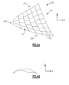
Figure 1 shows a highly schematic view of an example phased array inspection system incorporating a curved probe. -
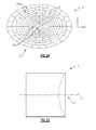
Figure 2A shows a front view of an example curved probe for use in theFigure 1 phased array inspection system. -
Figure 2B shows a side view of theFigure 2A curved probe in a second plane perpendicular to the first plane. -
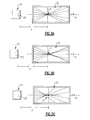
Figure 3A shows a schematic of a focused beam formation. -
Figure 3B shows a schematic for a beam with a positive stretch. -
Figure 3C shows a schematic for a beam with a negative stretch. - Referring to
Figures 1 to 2B , an example phasedarray inspection system 10 includes aprobe 14 coupled to acontroller 18. An outer surface of theprobe 14 includes acurved transducer array 22. Theprobe 14 is considered a curved probe because of thecurved transducer array 22. - The
curved transducer array 22 includes multipleindividual transducer elements 28. Each of thetransducer elements 28 can be pulsed (excited) to generate a sound wave. Sound waves generated by thetransducer elements 28 combine to form asound beam 32 that propagates from thecurved transducer array 22. - During an inspection procedure, the
beam 32 is directed toward thecomponent 34. In one example, theprobe 14 and thecomponent 34 are both submerged within a tank of water. The water facilitates transmission of thebeam 32. - Portions of the
beam 32 are reflected toward thecurved transducer array 22 after encountering a defect, inclusion, void, etc. within thecomponent 34. Thecurved transducer array 22 receives the reflected portions of thebeam 32, which are analyzed in a known way to reveal the defect, inclusion, void, etc. - In this example,
component 34 is a new or used component, such as a turbine disk in a high pressure turbine section of a turbomachine. Other examples may be used with other types of turbomachine components and components other than turbomachine components. Thesystem 10 could be used with any component or material that will be further processed to produce a component needing an inspection. - The example
curved transducer array 22 is particularly useful for inspecting thecomponent 34 because the curvature of the curved transducer is designed to facilitate formation of an appropriate sound beam insidecomponent 34. Flat (non-curved) arrays of transducers often cannot generate an appropriate sound beam in (typically curved) turbomachine components. - The example curved
transducer array 22 is curved in three directions. That is, thecurved transducer array 22 is curved relative to axes X, Y, and Z. (InFigure 2A , axis X extends outward from the page.) Other example probes are curved in at least two directions. - The
curved transducer array 22 includestransducer elements 28C near the center of the probe 14 (relative to the axis X) andtransducers elements 28P that are near the radial perimeter of theprobe 14. In this example, focal law calculator software utilizes coordinates of thetransducer elements curved transducer array 22. - The
example controller 18 is a stand-alone electronic device that is controlled by anexternal control software 44 running on a stand-alonepersonal computer 20. Thecontrol software 44 uses internally or externally generated focal laws that define how and when individual elements of an array are excited and how data received by individual array elements is processed. - A
focal law software 46 generates focal laws that are used by thecontrol software 44. Thefocal law software 46 is considered a focal law calculator in this example. - The example
personal computer 20 includes amemory portion 40 and aprocessor 42. Thefocal law software 46 produces focal law files. Thecontrol software 44 uses focal law files and produces phasing commands that are stored in thememory portion 40 and are sent by theprocessor 42 to thecontroller 18. Thecontroller 18 executes phasing commands and thus controls how thesound beam 32 is formed by controlling how and when thetransducer elements 28 generate pulses. - The example
focal law software 46 is a focal law calculator that generates focal law files. Thecontrol software 44 uses the focal law files and sends appropriate commands to thecontroller 18 that excite elements of thecurved transducer array 22 to form thesound beam 32. Examples of beam forming include stretching thesound beam 32, steering thesound beam 32, and focusing thesound beam 32. - In this example, the
sound beam 32 is stretched during the transmission or generation of a sound beam. Dynamic Depth Focusing (DDF) occurs upon reception of the reflected sound beam. DDF involves combining reflected waves. In the prior art, standard `off the-shelf focal law calculators do not have capability to form focused or stretched beams for a generally curved phased array probe. They also cannot program DDF for generally curved probes. - In this example, stretching the
sound beam 32 may involve a positive stretch or a negative stretch. Positive and negative are determined with reference to a nominal focus distance and whether central elements are focused closer or father than 'outer rim' elements. - For example, referring to
Figures 3A to 3C with continuing reference toFigures 1 to 2B , a nominal focus distance F is this distance between thetransducer array 22 and a point P when thetransducer elements 28 are focused on the point P. - The
individual transducer elements 28 of thearray 22 produce rays that combine to form thebeam 32. In theFigures 3A-3C , the size of thebeam 32 relative to thearray 22 has been increased for clarity.Figure 3A shows the beam focused on the point P.A positive stretch of thebeam 32 is achieved when thetransducer elements 28C are refocused at a distance less than the nominal focus distance F, and thetransducer elements 28P refocused at a distance greater than the nominal focus distance F. Thus, when thebeam 32 is positively stretched, waves from thetransducer elements 28C intersect an axis A of thebeam 32 closer to theprobe 14 than the waves from thetransducer elements 28P.Figure 3B shows a positive stretch of thebeam 32. - A negative stretch of the
beam 32 is achieved when thetransducer elements 28C are refocused at a distance greater than the nominal focus distance F, and thetransducer elements 28P - at a distance less than the nominal focus distance F. Thus, when thebeam 32 is negatively stretched, waves from thetransducer elements 28C intersect an axis A of thebeam 32 further from theprobe 14 than the waves from thetransducer elements 28P.Figure 3C shows a negative stretch of thebeam 32. - In this example, focal
law calculator software 46 executes the stretching Fn according to the algorithm (1).
- In algorithm (1), F is the nominal focus distance, Dstr is a desired amount of stretch, n is a number of the transducer element rings 28 within the
curved transducer array 22, and N is a total number of element rings within thecurved transducer array 22. In this example, the algorithm (1) is utilized with annular arrays of transducer elements such as thearray 22. - In this example, the
focal law software 46 includes a portion executing the algorithm (1) to stretch thebeam 32. - Another way the
focal law software 46 may stretch thebeam 32 is by controlling the distribution of focal points of the waves from thetransducers elements 28 within thecurved transducer array 22. Thefocal law software 46 may use the algorithm (2) to control the focal points.
- In the algorithm (2), ξ corresponds to stretch uniformity. When ξ=1, focusing distribution is uniform (
Figure 3A ). When ξ=2, distribution is denser near the far end of the range (Figure 3B ), when ξ=0 focusing is denser near the near end of the range. - The preceding description is exemplary rather than limiting in nature. Variations and modifications to the disclosed examples may become apparent to those skilled in the art that do not necessarily depart from the essence of this disclosure. Thus, the scope of legal protection given to this disclosure can only be determined by studying the following claims.
Claims (15)
- A component inspection method comprising:directing a wave from a curved array (22) of transducer elements (28) toward a component (34); andforming the wave (32) using a focal law calculator software (46).
- The component inspection method of claim 1, including dynamic depth focusing the wave (32) using the focal law calculator software (46).
- The component inspection method of claim 1 or 2, including stretching the wave (32) using the focal law calculator software (46).
- The component inspection method of any of claims 1 to 3, including steering the wave (32) using the focal law calculator software (46).
- The component inspection method of any preceding claim, wherein a surface of the curved array (22) of transducer element (28) is curved.
- A component inspection method comprising:directing a wave (32) from a transducer array (22) toward a component (34), the transducer array (22) being curved; andusing a focal law calculator software (46) to focus the wave (32), stretch the wave (32), steer the wave (32) or some combination of these.
- The component inspection method of claim 6, wherein the focal law calculator software (46) stretches the wave (32) using an algorithm:

wherein Fn is the amount of stretching, F is the nominal focus distance, Dstr is a desired amount of stretch, n is a number of transducer elements (28) within the transducer array (22), and N is a total number of elements (28) within the transducer array (22). - The component inspection method of any preceding claim, wherein the array (22) forms a portion of a phased array inspection system (10).
- The component inspection method of any preceding claim, wherein the focal law calculator software (46) is executed on a computer (20).
- A phased array inspection system (10), comprising:a curved array (22) of transducer elements (28); anda computer (20) that uses a focal law calculator to calculate focal law files, wherein a controller (18) controls a wave (32) generated by the curved array (22) of transducer elements (28) based on the focal law files.
- The phased array inspection system (10) of claim 10, wherein the controller (18) dynamic depth focuses the wave (32) based on the focal law files.
- The phased array inspection system (10) of claim 10 or 11, wherein the controller (18) stretches the wave (32) based on the focal law files.
- The phased array inspection system (10) of any of claims 10 to 12, wherein the controller (18) steers the wave (32) based on the focal law files.
- The phased array inspection system (10) of any of claims 10 to 13, including a probe (14), wherein an outwardly facing surface of the probe (14) includes a curved array (22) of transducer elements (28).
- The component inspection method or phased array inspection system (10) of any preceding claim, wherein the curved array (22) is curved in at least two dimensions.
Applications Claiming Priority (1)
| Application Number | Priority Date | Filing Date | Title |
|---|---|---|---|
| US13/353,875 US9234878B2 (en) | 2012-01-19 | 2012-01-19 | Component inspection using a curved transducer array |
Publications (2)
| Publication Number | Publication Date |
|---|---|
| EP2618178A2 true EP2618178A2 (en) | 2013-07-24 |
| EP2618178A3 EP2618178A3 (en) | 2015-04-15 |
Family
ID=47721973
Family Applications (1)
| Application Number | Title | Priority Date | Filing Date |
|---|---|---|---|
| EP20130150407 Withdrawn EP2618178A3 (en) | 2012-01-19 | 2013-01-07 | Component inspection using a curved transducer array |
Country Status (2)
| Country | Link |
|---|---|
| US (1) | US9234878B2 (en) |
| EP (1) | EP2618178A3 (en) |
Cited By (1)
| Publication number | Priority date | Publication date | Assignee | Title |
|---|---|---|---|---|
| EP3044581B1 (en) * | 2013-09-11 | 2019-10-30 | General Electric Company | Rolling curved array ultrasonic scanner |
Families Citing this family (6)
| Publication number | Priority date | Publication date | Assignee | Title |
|---|---|---|---|---|
| US20160059044A1 (en) | 2009-10-12 | 2016-03-03 | Kona Medical, Inc. | Energy delivery to intraparenchymal regions of the kidney to treat hypertension |
| US11998266B2 (en) | 2009-10-12 | 2024-06-04 | Otsuka Medical Devices Co., Ltd | Intravascular energy delivery |
| WO2014164363A1 (en) * | 2013-03-09 | 2014-10-09 | Kona Medical, Inc. | Transducers, systems, and manufacturing techniques for focused ultrasound therapies |
| US10925579B2 (en) | 2014-11-05 | 2021-02-23 | Otsuka Medical Devices Co., Ltd. | Systems and methods for real-time tracking of a target tissue using imaging before and during therapy delivery |
| JP7070057B2 (en) * | 2018-05-09 | 2022-05-18 | セイコーエプソン株式会社 | Double feed detector and electronic equipment |
| JP7099040B2 (en) | 2018-05-11 | 2022-07-12 | セイコーエプソン株式会社 | Double feed detection device, double feed detection method and electronic equipment |
Family Cites Families (11)
| Publication number | Priority date | Publication date | Assignee | Title |
|---|---|---|---|---|
| US4276779A (en) | 1979-03-29 | 1981-07-07 | Raytheon Company | Dynamically focussed array |
| US6312386B1 (en) | 1999-02-19 | 2001-11-06 | Acuson Corporation | Medical ultrasound imaging system with composite delay profile |
| US6310831B1 (en) | 2000-02-15 | 2001-10-30 | Richard F Dillman | Method and system for aperture adjustment in steered phased array transducer systems |
| WO2002054379A2 (en) * | 2001-01-05 | 2002-07-11 | Angelsen Bjoern A J | Annular array |
| US7010982B2 (en) | 2004-04-30 | 2006-03-14 | General Electric Company | Method of ultrasonically inspecting airfoils |
| US7305885B2 (en) | 2004-09-30 | 2007-12-11 | General Electric Company | Method and apparatus for phased array based ultrasonic evaluation of rail |
| US7245063B2 (en) * | 2004-11-12 | 2007-07-17 | Honeywell International, Inc. | Optimized ultrasonic phased array transducer for the inspection of billet material |
| US7428842B2 (en) | 2005-06-20 | 2008-09-30 | Siemens Power Generation, Inc. | Phased array ultrasonic testing system and methods of examination and modeling employing the same |
| DE102008002859A1 (en) * | 2008-05-28 | 2009-12-03 | Ge Inspection Technologies Gmbh | Apparatus and method for non-destructive testing of articles by ultrasound and use of matrix phased array probes |
| WO2011024074A2 (en) * | 2009-08-26 | 2011-03-03 | Insightec Ltd. | Asymmetric phased-array ultrasound transducer |
| CN101858972B (en) | 2010-03-23 | 2013-01-30 | 深圳市蓝韵实业有限公司 | Multi-beam synthesis method and device based on delay parameter real-time calculation and assembly line |
-
2012
- 2012-01-19 US US13/353,875 patent/US9234878B2/en active Active
-
2013
- 2013-01-07 EP EP20130150407 patent/EP2618178A3/en not_active Withdrawn
Non-Patent Citations (1)
| Title |
|---|
| None |
Cited By (1)
| Publication number | Priority date | Publication date | Assignee | Title |
|---|---|---|---|---|
| EP3044581B1 (en) * | 2013-09-11 | 2019-10-30 | General Electric Company | Rolling curved array ultrasonic scanner |
Also Published As
| Publication number | Publication date |
|---|---|
| US9234878B2 (en) | 2016-01-12 |
| EP2618178A3 (en) | 2015-04-15 |
| US20130191042A1 (en) | 2013-07-25 |
Similar Documents
| Publication | Publication Date | Title |
|---|---|---|
| EP2618178A2 (en) | Component inspection using a curved transducer array | |
| JP4776707B2 (en) | Ultrasonic imaging device | |
| KR101610608B1 (en) | Apparatus for measuring characteristics of metal material | |
| JP4821848B2 (en) | Defect inspection apparatus and defect inspection method | |
| US20150153310A1 (en) | Turbine blade testing device and testing method thereof | |
| Piedade et al. | Minimum transmission events for fast ultrasonic TFM imaging: A comparative study | |
| EP3722801B1 (en) | Ultrasonic flaw detection method | |
| Zhang et al. | Nanosecond shock wave-induced surface acoustic waves and dynamic fracture at fluid-solid boundaries | |
| Xi et al. | Simulation and performance study of circular ultrasonic array for tubes’ internal inspection | |
| US7950283B2 (en) | Ultrasound prediction of workpiece deformation | |
| CN110261489B (en) | Calculation method of sound field diffusion angle of radiation deflection of linear phased array ultrasonic oblique probe | |
| CN112434467B (en) | Underwater rotator target low-target-strength appearance design method | |
| Varray et al. | Nonlinear radio frequency image simulation for harmonic imaging: Creanuis | |
| Wang et al. | NDT beamforming algorithm based on amplitude distribution correlation factor | |
| Kirkpatrick et al. | Row–column addressed arrays for nondestructive evaluation applications | |
| Maghlaoui et al. | Numerical simulation of the transient ultrasonic wave reflection at a liquid-solid interface | |
| JP5112261B2 (en) | Phased array probe and method for determining its specifications | |
| JP4359892B2 (en) | Ultrasonic flaw detection method | |
| Lupien et al. | Improved titanium billet inspection sensitivity through optimized phased array design, Part I: Design technique, modeling and simulation | |
| KR102354915B1 (en) | Ultrasonic wave delayed value determining device and ultrasonic wave delayed value determining method and defect position of welding portion determining method | |
| Karzova et al. | Nonlinear effects in ultrasound fields of diagnostic-type transducers used for kidney stone propulsion: Characterization in water | |
| Vanhoye et al. | Design by simulation of the UT array inspection of a nozzle with a flexible probe: Definition of 3D trajectories and focusing parameters | |
| Barber et al. | Optimization of element length for imaging small volumetric reflectors with linear ultrasonic arrays | |
| Brown et al. | Quantifying performance of ultrasonic immersion inspection using phased arrays for curvilinear disc forgings | |
| Hu et al. | An improved discrete elliptic imaging algorithm based on guided waves for defect localisation in curved plates |
Legal Events
| Date | Code | Title | Description |
|---|---|---|---|
| PUAI | Public reference made under article 153(3) epc to a published international application that has entered the european phase |
Free format text: ORIGINAL CODE: 0009012 |
|
| AK | Designated contracting states |
Kind code of ref document: A2 Designated state(s): AL AT BE BG CH CY CZ DE DK EE ES FI FR GB GR HR HU IE IS IT LI LT LU LV MC MK MT NL NO PL PT RO RS SE SI SK SM TR |
|
| AX | Request for extension of the european patent |
Extension state: BA ME |
|
| PUAL | Search report despatched |
Free format text: ORIGINAL CODE: 0009013 |
|
| AK | Designated contracting states |
Kind code of ref document: A3 Designated state(s): AL AT BE BG CH CY CZ DE DK EE ES FI FR GB GR HR HU IE IS IT LI LT LU LV MC MK MT NL NO PL PT RO RS SE SI SK SM TR |
|
| AX | Request for extension of the european patent |
Extension state: BA ME |
|
| RIC1 | Information provided on ipc code assigned before grant |
Ipc: G01N 29/26 20060101ALI20150311BHEP Ipc: G01N 29/22 20060101ALI20150311BHEP Ipc: G01N 29/06 20060101ALI20150311BHEP Ipc: G01S 15/89 20060101AFI20150311BHEP Ipc: G10K 11/34 20060101ALI20150311BHEP Ipc: G01N 29/04 20060101ALI20150311BHEP Ipc: G01N 29/24 20060101ALI20150311BHEP Ipc: B06B 1/06 20060101ALI20150311BHEP |
|
| 17P | Request for examination filed |
Effective date: 20151015 |
|
| RBV | Designated contracting states (corrected) |
Designated state(s): AL AT BE BG CH CY CZ DE DK EE ES FI FR GB GR HR HU IE IS IT LI LT LU LV MC MK MT NL NO PL PT RO RS SE SI SK SM TR |
|
| RAP1 | Party data changed (applicant data changed or rights of an application transferred) |
Owner name: UNITED TECHNOLOGIES CORPORATION |
|
| STAA | Information on the status of an ep patent application or granted ep patent |
Free format text: STATUS: EXAMINATION IS IN PROGRESS |
|
| 17Q | First examination report despatched |
Effective date: 20170817 |
|
| STAA | Information on the status of an ep patent application or granted ep patent |
Free format text: STATUS: THE APPLICATION HAS BEEN WITHDRAWN |
|
| 18W | Application withdrawn |
Effective date: 20201030 |