EP2618106A1 - Electronic level and leveling rod for electronic level - Google Patents
Electronic level and leveling rod for electronic level Download PDFInfo
- Publication number
- EP2618106A1 EP2618106A1 EP11824847.5A EP11824847A EP2618106A1 EP 2618106 A1 EP2618106 A1 EP 2618106A1 EP 11824847 A EP11824847 A EP 11824847A EP 2618106 A1 EP2618106 A1 EP 2618106A1
- Authority
- EP
- European Patent Office
- Prior art keywords
- pattern
- measurement
- electronic level
- height
- leveling rod
- Prior art date
- Legal status (The legal status is an assumption and is not a legal conclusion. Google has not performed a legal analysis and makes no representation as to the accuracy of the status listed.)
- Granted
Links
Images


Classifications
-
- G—PHYSICS
- G01—MEASURING; TESTING
- G01C—MEASURING DISTANCES, LEVELS OR BEARINGS; SURVEYING; NAVIGATION; GYROSCOPIC INSTRUMENTS; PHOTOGRAMMETRY OR VIDEOGRAMMETRY
- G01C9/00—Measuring inclination, e.g. by clinometers, by levels
- G01C9/02—Details
- G01C9/06—Electric or photoelectric indication or reading means
-
- G—PHYSICS
- G01—MEASURING; TESTING
- G01C—MEASURING DISTANCES, LEVELS OR BEARINGS; SURVEYING; NAVIGATION; GYROSCOPIC INSTRUMENTS; PHOTOGRAMMETRY OR VIDEOGRAMMETRY
- G01C15/00—Surveying instruments or accessories not provided for in groups G01C1/00 - G01C13/00
- G01C15/02—Means for marking measuring points
- G01C15/06—Surveyors' staffs; Movable markers
Definitions
- the present invention relates to an electronic level (leveling instrument) and a leveling rod for the electronic level (hereinafter, simply described as leveling rod).
- An electronic level reads a barcode to automatically determine a height of a measurement point by use of a bar-coded leveling rod as a graduation.
- a bar-coded leveling rod as a graduation.
- this electronic level 2 is for collimating a leveling rod 1, to measure a height h of a collimation position.
- a barcode in which black marks 11 are drawn on a white surface is indicated on the leveling rod 1.
- the leveling rod 1 is usually set in an upright state. However, in some cases, the leveling rod 1 may be set in an upside-down state in which the leveling rod 1 is vertically inverted, with a ceiling surface C as a reference as illustrated. In this case, a height h from the ceiling surface C to a collimation position is measured.
- the vertical width dimensions of the marks 11 are not all the same in dimension, and the marks 11 with several types of dimensions are arrayed in a predetermined order.
- a barcode pattern is shown in Fig. 2 .
- the marks 11 indicated on the leveling rod 1 are arrayed at regular pitches P. Given that the total length of the leveling rod 1 is 4 m and the pitch P is 16 mm, it is possible to indicate 249 marks 11 on the leveling rod 1.
- the electronic level 2 is configured to determine the width dimensions of the marks 11, to correspond to six types of integers of 0, 1, 2, 3, 4, and 5 as shown by N in Fig. 2 . Accordingly, a sequence created from the marks 11 is expressed by the six types of integers, and is, for example, the following sequence (1).
- the number of integers to be retrieved from the aforementioned sequence (1) is set to 5. For example, when five integers are retrieved from the left endpoint of the sequence (1), the following permutation (2) is obtained.
- the electronic level 2 stores the same sequence as the above-described sequence (1) as table values, and determines which portion in the table values the retrieved permutation (2) or (3) corresponds to, to determine a height h of the collimation position from that position.
- a permutation (4) of integers retrieved from a portion of the aforementioned permutation (2) is as follows.
- the permutation (4) is set so as not to correspond to any portion of the above-described sequence (1). Accordingly, because there is no corresponding portion when the leveling rod 1 is in an upside-down state, a microcomputer 3 is capable of judging that the leveling rod 1 is in an upside-down state, to indicate that effect, and inverts the order of the retrieved permutation (4), to compare the inverted permutation with the aforementioned sequence (1), thus being capable of determining the height h.
- the electronic level 2 stores this sequence (5) in addition to the sequence (1). Meanwhile, when the types of integers composing the sequence (5) are three types in this way, it is necessary to increase the number of integers to be retrieved from five for reliable height measurement, and therefore, eight integers are to be retrieved.
- nonsequential eight integers may be retrieved, so as to form a permutation (7).
- an objective optical system an objective lens and a focusing lens
- a slope automatic compensation mechanism (compensator) 22
- a collimating optical system is to pass through the beam splitter 23 and an image optical system is to be split into the line sensor 24.
- the collimating optical system is composed of the objective optical system 21, the slope automatic compensation mechanism 22, the beam splitter 23, a focusing glass 20a, and an eye lens 20b.
- the image optical system is composed of the objective optical system 21, the slope automatic compensation mechanism 22, the beam splitter 23, and the line sensor 24.
- the line sensor 24 converts the light-received image of the leveling rod 1 into an electric signal, to output it to an amplifier 25.
- the signal amplified in the amplifier 25 is synchronized with a clock signal of a clock driver 26, to be sampled and held, to be converted into a digital signal in an A/D converter 27.
- the signal converted into the digital signal is stored in a RAM 28.
- the microcomputer 3 determines width dimensions of the respective marks 11 captured within the visual field of the collimating optical system based on the signal stored in the RAM 28, and determines a permutation of a predetermined number of integers from a predetermined number of marks 11 centering on the collimation point. For example, in the case of measurement within a predetermined distance, as shown in Fig. 4 , a permutation composed of five integers is determined from the width dimensions of the N - 2nd, N - 1st, Nth, N + 1st, and N + 2nd marks 11. Then, the permutation is compared with the table values of the sequence (1) or (5) stored in advance in a ROM 31, to determine the height h of the collimation position.
- a drive circuit 29 is a circuit that controls the operation of the line sensor 24. Further, because the optical axis of the collimating optical system and the optical axis of the image optical system correspond to one another, the collimation point on the leveling rod 1 and the collimation point of the image optical system correspond to one another.
- a measurement program performed by the microcomputer 3 in order to perform a height measurement with this electronic level 2 will be described by a flowchart of Fig. 5 .
- Step S1 When a measurement program is started, the process proceeds to Step S1, to acquire an output signal from the line sensor 24.
- Step S2 the process proceeds to Step S2, to perform a frequency measurement with respect to the acquired output signal.
- the marks 11 are disposed at regular pitches B on the leveling rod 1, it is possible to detect a frequency component according to the array of the marks 11.
- the frequency is, specifically, the number of the marks 11 formed as an image on a predetermined number of pixels on the line sensor 24, provided that the predetermined number of pixels is divided by the number, it is possible to determine the pitch P of the marks 11 formed as the image on the line sensor 24 as a length in units of pixels.
- Step S3 it is checked whether or not the frequency measurement is successful.
- the frequency measurement fails, it is impossible to calculate a distance up to the leveling rod1, and therefore, the process proceeds to Step S8, to indicate an error in distance measurement, and the measurement program is terminated.
- a distance D up to the leveling rod 1 is determined by the following formula.
- Step S3 When the frequency measurement is successful in Step S3, the process proceeds to Step S4, to perform a height measurement as described later. Next, it is checked whether or not the height measurement is successful. When the height measurement is successful, the process proceeds to Step S6, to indicate measured values of the height and distance, and the measurement program is terminated. When the height measurement fails, the process proceeds to Step S7, to indicate an error in height measurement, and the measurement program is terminated.
- Step S4 The height measurement in Step S4 will be described in more detail by Figs. 7 and 8 .
- Step S3 the process proceeds to Step S41, to measure the width dimensions of the black marks 11.
- an output signal from the line sensor 24 changes into one as in Fig. 8B .
- the output signal from the line sensor 24 is differentiated, as shown in Fig. 8C , falling pulses and rising pulses are detected. Therefore, it is possible to detect the width dimensions of the respective marks 11 according to intervals w of the both pulses.
- Step S42 to perform an encoding process of converting the widths of the respective marks 11 into integers (refer to Fig. 2 ).
- Step S43 to search a corresponding place between a permutation obtained by converting the widths of the respective marks 11 into integers and the sequence stored in advance.
- Step S44 to perform a height measurement when a corresponding place is found, and the process proceeds to the following Step S5.
- Step S5 When a corresponding place is not found, the microcomputer 3 stores that the height measurement fails, and the process similarly proceeds to the following Step S5.
- the distance between the electronic level 2 and the leveling rod 1 is shorter than a predetermined distance, it is possible to reliably discriminate the width dimensions of all types of the marks 11. Therefore, it suffices that the number of the marks 11 to be retrieved in order to create a permutation of integers is small, which makes it possible to shorten the distance between the leveling rod 1 and the electronic level 2 by that amount.
- the distance between the leveling rod 1 and the electronic level 2 is longer than the predetermined distance, at least two types of the marks 11 whose width dimensions are approximate to each other are discriminated as the same dimension, to be expressed as the same integer, thereby lengthening a distance by which it is possible to discriminate the marks 11.
- the types of integers corresponding to the respective marks 11 are decreased, and the number of the marks 11 necessary for specifying a collimation position is increased.
- the distance between the leveling rod 1 and the electronic level 2 is increased, the number of the marks 11 within the visual field of the collimating optical system is increased, and therefore, it is also possible to reliably perform a long distance measurement.
- a permutation which is obtained by inverting a permutation retrieved from the respective marks 11 as well is to differ from a permutation retrieved from any position of the aforementioned sequence (1), there is no corresponding place in the aforementioned sequence (1) in a permutation obtained in the case where the leveling rod 1 is in an upside-down state, and therefore, it is possible to judge that the leveling rod 1 may be set in an upside-down state. Then, when there is a corresponding portion in an inverted permutation in which the retrieved permutation is inverted in the opposite direction, it is judged that the leveling rod 1 is inverted, and the height is measured.
- the electronic level 2 determines a permutation of integers based on the width dimensions of the marks 11, to determine a height of a collimation position, and is therefore hardly affected by a disturbance. Further, because the types of the integers composing a permutation are increased and decreased according to the length of the distance between the leveling rod 1 and the electronic level 2, it is possible to expand a measurable range between the leveling rod 1 and the electronic level 2.
- Patent Document 2 there is disclosed an electronic level and a leveling rod which are capable of expanding a measurable range. However, because there is little relationship with this invention, descriptions thereof will be omitted.
- the present invention has been achieved in consideration of the above-described problem, and an object of the present invention is to be capable of easily expanding a measurable range, so as to measure the both of a long distance measurement and a short distance measurement, and not to perform an incorrect measurement even when a conventional leveling rod for electronic level is mixed and used.
- a leveling rod for electronic level having a pattern forming a grayscale by arraying a plurality of bar-shapedmarks along a longitudinal direction at regular pitches
- the leveling rod for electronic level has, as the pattern, a first pattern in which a grayscale is formed according to a predetermined rule for a measurement within a first distance range, and a second pattern which is enlarged or reduced with respect to a pattern in which the grayscale of the first pattern is inverted for a measurement within a second distance range different from the first distance range.
- the leveling rod for electronic level according to the first aspect has a first surface and a second surface which differ in orientation, in which the first pattern is formed on the first surface, and the second pattern is formed on the second surface.
- an electronic level including a line sensor which generates an output signal according to the first pattern or the second pattern formed on the leveling rod for electronic level according to the first or second aspect, and height measurement means for measuring a height of a collimation point from the output signal from the line sensor so as to correspond to the first pattern
- the electronic level further includes grayscale inversion means for inverting the grayscale of the output signal from the line sensor in order to correspond to the secondpattern, and height correction means for correcting the height measured by the height measurement means according to a reduction scale of the second pattern with respect to the first pattern
- the electronic level is also capable of performing a height measurement by use of the leveling rod for electronic level according to the first or second aspect.
- the electronic level according to the third aspect further including remeasurement means for making the height measurement means perform a remeasurement after the correspondence to the first pattern is changed to the correspondence to the second pattern, or the correspondence to the second pattern is changed to the correspondence to the first pattern in a case where it is impossible to measure a height of a collimation point with the height measurement means.
- the electronic level according to the fourth aspect further including pattern storing means for storing whether it is possible to perform a height measurement with the first pattern or the second pattern, the electronic level performs a next first measurement so as to correspond to the stored pattern.
- the leveling rod for electronic level has the first pattern and the second pattern which is enlarged or reduced with respect to the pattern in which the grayscale of the first pattern is inverted, provided that the electronic level according to the third aspect of the invention is used, it is possible to perform a height measurement by use of either of the first pattern or the second pattern, and therefore, it is possible to perform a measurement within the first distance range by use of the first pattern, and it is possible to perform a measurement within the second distance range of a longer distance or a shorter distance than the first distance range by use of the second pattern, which makes it possible to easily expand the measurement range.
- the leveling rod for electronic level has the first surface and the second surface which differ in orientation, and the first pattern is formed on the first surface, and the second pattern is formed on the second surface, it is possible to expand the measurement range with the one leveling rod for electronic level, that is convenient.
- the electronic level includes the height measurement means for measuring a height of a collimation point from the output signal from the line sensor so as to correspond to the first pattern, provided that a measurement is performed by use of the first pattern, it is possible to perform the measurement in a conventional manner.
- a measurement is performed by use of the second pattern, by inverting the grayscale of an output signal from the line sensor by the grayscale inversion means, it is possible to read a height from the second pattern with the height measurement means.
- the second pattern is enlarged or reduced with respect to the first pattern, it is impossible to obtain an accurate height as it is.
- the electronic level further includes the remeasurement means for making the height measurement means perform a remeasurement after the correspondence to the first pattern is changed to the correspondence to the second pattern, or the correspondence to the second pattern is changed to the correspondence to the first pattern in a case where it is impossible to measure a height of a collimation point with the height measurement means, it is possible to automatically judge the first pattern or the second pattern, to be able to perform a measurement without giving a manual instruction to perform a measurement with the first pattern or the second pattern, that is convenient.
- the electronic level further includes the pattern storing means for storing whether it is possible to perform a height measurement with the first pattern or the second pattern, and the electronic level performs a next first measurement so as to correspond to the stored pattern. Therefore, wasteful measurements are reduced, which makes it possible to promptly complete the measurement.
- a leveling rod 1 in the present embodiment has, as shown in Fig. 9 , in addition to a first pattern 1A which is a barcode pattern which is the same as that of the leveling rod 1 disclosed in the aforementioned Patent Document 1, a second pattern 1B of a similar shape which is reduced with respect to one 1R in which the black and white (grayscale) of the first pattern 1A is inverted.
- the two patterns 1A and 1B may be respectively drawn on the surface and rear surface of the one leveling rod 1, or may be respectively drawn on the one surfaces of the two leveling rods 1, or may be respectively drawn on the first surface and the second surface, which differ in orientation, of the leveling rod 1 having polygonal sections.
- an electronic level 2 of the present embodiment is the same as the electronic level 2 disclosed in the aforementioned Patent Document 1 except for the point that a measurement program by which it is possible to perform a height measurement from not only the first pattern 1A drawn on the leveling rod 1, but also from the second pattern 1B is provided.
- Step S1 to acquire an output signal from a line sensor 24.
- Step S2 to perform a frequency measurement with respect to the acquired output signal.
- Step S3 it is checked whether or not the frequency measurement is successful. Until this point, and when the frequency measurement fails, the process proceeds to Step S8, to indicate an error in distance measurement, and the measurement is terminated, which are the same as those disclosed in the aforementioned Patent Document 1.
- Step S10 When the frequency measurement is successful in Step S3, the process proceeds to Step S10, to initialize control variables J and K.
- the output signal from the line sensor 24 is inverted (refer to B' in Fig. 11 ). Thereafter, provided that the inverted output signal is differentiated in the same way in a conventional manner (refer to C in Fig. 11 ), it is possible to obtain the widths w of the marks 11.
- Step S12 to perform processing of inverting the output signal from the line sensor 24, and thereafter, the process proceeds to Step S4, to perform a height measurement.
- Step S4 is the same as that of the conventional invention disclosed in Patent Document 1.
- the process directly proceeds to Step S4, to perform a height measurement.
- Steps S10 to S12 are equivalent to the grayscale inversion means described in the third aspect
- Step S4 is equivalent to the height measurement means described in the third aspect.
- Step S21 After the height measurement is performed in Step S4, the process proceeds to Step S21, and it is checked whether or not the height measurement is successful.
- Step S22 When the height measurement fails, the process proceeds to Step S22, and it is checked whether or not it is an error other than an encoding error.
- An encoding error means a failure in detecting the marks 11, a failure in converting width dimensions of the marks 11 into integers, and that it is impossible to find a corresponding point between a permutation converted into integers and the sequence stored in advance.
- Step S7 When it is an error other than an encoding error, the process proceeds to Step S7, to indicate an error in height measurement, and the process is terminated.
- the setting is a remeasurement
- the process proceeds to Step S7, to indicate an error in height measurement, and the process is terminated.
- Steps S21 to S24 are equivalent to the remeasurement means described in the fourth aspect.
- Step S40 Steps S31 to S32 are equivalent to the height correction means described in the third aspect.
- Step S40 to store a value of the control variable J. This is because the leveling rod 1 is moved to an adjacent measurement point also in the next measurement, and therefore, the same pattern may be used inmanycases. Then, the process proceeds to Step S6, to indicate the measured result, and the process is terminated.
- Step S40 is equivalent to the pattern storage means described in the fifth aspect.
- a measurement is performed by use of the first pattern 1A
- a measurement is performed by use of the second pattern 1B, by inverting the grayscale of an output signal from the line sensor 24, it is possible to read a height from the second pattern 1B.
- the second pattern 1B is reduced with respect to the first pattern 1A, it is impossible to obtain an accurate height as it is.
- a height is made to be corrected according to a reduction scale of the second pattern 1B with respect to the first pattern 1A, to obtain a correct height.
- the correspondence to the first pattern 1A is changed to the correspondence to the second pattern 1B, or the correspondence to the second pattern 1B is changed to the correspondence to the first pattern 1A, to make the electronic level perform a remeasurement. Therefore, it is possible to automatically judge the first pattern 1A or the second pattern 1B, to be able to perform a measurement without giving a manual instruction to perform a measurement with the first pattern 1A or the second pattern 1B, that is convenient.
- the pattern disclosed in the aforementioned Patent Document 1 is adopted as a pattern drawn on the leveling rod 1.
- any of the patterns which are used as leveling rods for electronic level may be adopted when there is a means capable of discriminating a state in which the grayscale of the pattern is inverted.
- the pattern disclosed in the aforementioned Patent Document 2 may be adopted.
- the second pattern 1B drawn on the leveling rod 1 has a similar shape which is reduced with respect to the pattern 1R in which the black and white (grayscale) of the first pattern 1A is inverted.
- the second pattern 1B may have a similar shape which is enlarged with respect to the pattern 1R in contrast. In this case, by use of the second pattern 1B, it is possible to perform a much longer distance measurement.
- the leveling rod 1 may be a triangular prism shape, and the first pattern 1A may be drawn on the first surface, the second pattern 1B having a similar shape which is reduced with respect to the pattern 1R in which the black and white (grayscale) of the first pattern 1A is inverted may be drawn on the second surface, and a third pattern having a similar shape which is enlarged with respect to the pattern 1R in which the black and white (grayscale) of the first pattern 1A is inverted may be drawn on the third surface.
- Step S40 may be omitted.
- Step S40 may be omitted, and because the height measurement is not likely to fail, Steps S22 to S24 may be omitted.
- Step S40 may be omitted, on the other hand, it is acceptable that Steps S22 to S24 may be left.
Landscapes
- Physics & Mathematics (AREA)
- Engineering & Computer Science (AREA)
- General Physics & Mathematics (AREA)
- Radar, Positioning & Navigation (AREA)
- Remote Sensing (AREA)
- Length Measuring Devices By Optical Means (AREA)
- Measurement Of Length, Angles, Or The Like Using Electric Or Magnetic Means (AREA)
Abstract
Description
- The present invention relates to an electronic level (leveling instrument) and a leveling rod for the electronic level (hereinafter, simply described as leveling rod).
- An electronic level reads a barcode to automatically determine a height of a measurement point by use of a bar-coded leveling rod as a graduation. With such an electronic level, there is a defect that the electronic level is easily affected by a disturbance, to be easily incapable of measurement due to, for example, a background of a leveling rod, or an obstacle between the leveling rod and the electronic level.
- The applicant has filed an application for an electronic level which is hardly affected by a disturbance in order to solve the above-described defect (refer to the following Patent Document 1). First, this electronic level will be described.
- As shown in
Fig. 1 , thiselectronic level 2 is for collimating aleveling rod 1, to measure a height h of a collimation position. A barcode in whichblack marks 11 are drawn on a white surface is indicated on theleveling rod 1. Theleveling rod 1 is usually set in an upright state. However, in some cases, theleveling rod 1 may be set in an upside-down state in which theleveling rod 1 is vertically inverted, with a ceiling surface C as a reference as illustrated. In this case, a height h from the ceiling surface C to a collimation position is measured. The vertical width dimensions of themarks 11 are not all the same in dimension, and themarks 11 with several types of dimensions are arrayed in a predetermined order. - A barcode pattern is shown in
Fig. 2 . Themarks 11 indicated on theleveling rod 1 are arrayed at regular pitches P. Given that the total length of theleveling rod 1 is 4 m and the pitch P is 16 mm, it is possible to indicate 249marks 11 on theleveling rod 1. As the vertical width dimensions of themarks 11, six types of 3 mm, 4 mm, 7 mm, 8 mm, 11 mm, and 12 mm are used. Theelectronic level 2 is configured to determine the width dimensions of themarks 11, to correspond to six types of integers of 0, 1, 2, 3, 4, and 5 as shown by N inFig. 2 . Accordingly, a sequence created from themarks 11 is expressed by the six types of integers, and is, for example, the following sequence (1). -

- Here, in the case where an arbitrary number of integers are retrieved from the sequence (1), to create a permutation, it is necessary for a permutation which is created by retrieving integers from one place to differ from a permutation which is created by retrieving integers from any other place. Further, it is necessary for a permutation which is obtained from the
leveling rod 1 in an upside-down state to differ from any one of the permutations which are obtained when theleveling rod 1 is in an upright state. Then, the number of integers to be retrieved from the aforementioned sequence (1) is set to 5. For example, when five integers are retrieved from the left endpoint of the sequence (1), the following permutation (2) is obtained. -

- However, in the case where five integers are retrieved, there is no need for these integers to be necessarily sequential. For example, in the case where the
mark 11 corresponding to the third integer from the left is hidden by an obstacle or the like between theleveling rod 1 and theelectronic level 2, the integer which is hidden to be unclear may be expressed as *, to obtain the following sequence. -

- On the other hand, the
electronic level 2 stores the same sequence as the above-described sequence (1) as table values, and determines which portion in the table values the retrieved permutation (2) or (3) corresponds to, to determine a height h of the collimation position from that position. - Further, when the
leveling rod 1 is in an upside-down state, a permutation (4) of integers retrieved from a portion of the aforementioned permutation (2) is as follows. -

- The permutation (4) is set so as not to correspond to any portion of the above-described sequence (1). Accordingly, because there is no corresponding portion when the
leveling rod 1 is in an upside-down state, amicrocomputer 3 is capable of judging that theleveling rod 1 is in an upside-down state, to indicate that effect, and inverts the order of the retrieved permutation (4), to compare the inverted permutation with the aforementioned sequence (1), thus being capable of determining the height h. - Meanwhile, a distance between the
leveling rod 1 and theelectronic level 2 is increased, the number of themarks 11 positioned within the visual field of a collimating optical system is increased. However, the image of themarks 11 is made smaller, which lowers the accuracy of discrimination of width dimensions. Then, when it is judged from the size of the image of theleveling rod 1 that the distance between theleveling rod 1 and theelectronic level 2 exceeds a predetermined value by stadia, as shown by F inFig. 2 ,3 mm and 4 mm are discriminated as the same dimension, so as to correspond to 0, 7 mm and 8 mm are discriminated as the same dimension, so as to correspond to 1, and 11 mm and 12 mm are discriminated as the same dimension, so as to correspond to 2. In this way, the following sequence (5) expressed by three types of integers is obtained. -

- The
electronic level 2 stores this sequence (5) in addition to the sequence (1). Meanwhile, when the types of integers composing the sequence (5) are three types in this way, it is necessary to increase the number of integers to be retrieved from five for reliable height measurement, and therefore, eight integers are to be retrieved. - For example, when eight integers are taken from the left endpoint of the sequence (5), the following permutation (6) is obtained.
-

- Further, in the case where some (for example, two)
marks 11 are hidden to be not discriminable, nonsequential eight integers may be retrieved, so as to form a permutation (7). -

- Then, which portion of the sequence (5) the permutation (6) or (7) corresponds to is determined, to determine a height h of the collimation position. Further, when the
leveling rod 1 is in an upside-down state, the obtained permutation (6) or (7) is inverted, to determine a height h from the inverted permutation and the sequence (5). - Meanwhile, as shown in
Fig. 3 , an objective optical system (an objective lens and a focusing lens) 21 and a slope automatic compensation mechanism (compensator) 22 are provided inside theelectron level 2, a light-received image of theleveling rod 1 is split into aline sensor 24 by abeam splitter 23. A collimating optical system is to pass through thebeam splitter 23 and an image optical system is to be split into theline sensor 24. - The collimating optical system is composed of the objective
optical system 21, the slopeautomatic compensation mechanism 22, thebeam splitter 23, a focusingglass 20a, and aneye lens 20b. The image optical system is composed of the objectiveoptical system 21, the slopeautomatic compensation mechanism 22, thebeam splitter 23, and theline sensor 24. Theline sensor 24 converts the light-received image of theleveling rod 1 into an electric signal, to output it to anamplifier 25. The signal amplified in theamplifier 25 is synchronized with a clock signal of aclock driver 26, to be sampled and held, to be converted into a digital signal in an A/D converter 27. The signal converted into the digital signal is stored in aRAM 28. Themicrocomputer 3 determines width dimensions of therespective marks 11 captured within the visual field of the collimating optical system based on the signal stored in theRAM 28, and determines a permutation of a predetermined number of integers from a predetermined number ofmarks 11 centering on the collimation point. For example, in the case of measurement within a predetermined distance, as shown inFig. 4 , a permutation composed of five integers is determined from the width dimensions of the N - 2nd, N - 1st, Nth, N + 1st, and N +2nd marks 11. Then, the permutation is compared with the table values of the sequence (1) or (5) stored in advance in aROM 31, to determine the height h of the collimation position. Adrive circuit 29 is a circuit that controls the operation of theline sensor 24. Further, because the optical axis of the collimating optical system and the optical axis of the image optical system correspond to one another, the collimation point on theleveling rod 1 and the collimation point of the image optical system correspond to one another. - A measurement program performed by the
microcomputer 3 in order to perform a height measurement with thiselectronic level 2 will be described by a flowchart ofFig. 5 . - When a measurement program is started, the process proceeds to Step S1, to acquire an output signal from the
line sensor 24. Next, the process proceeds to Step S2, to perform a frequency measurement with respect to the acquired output signal. Because themarks 11 are disposed at regular pitches B on theleveling rod 1, it is possible to detect a frequency component according to the array of themarks 11. Because the frequency is, specifically, the number of themarks 11 formed as an image on a predetermined number of pixels on theline sensor 24, provided that the predetermined number of pixels is divided by the number, it is possible to determine the pitch P of themarks 11 formed as the image on theline sensor 24 as a length in units of pixels. Next, the process proceeds to Step S3, and it is checked whether or not the frequency measurement is successful. When the frequency measurement fails, it is impossible to calculate a distance up to the leveling rod1, and therefore, the process proceeds to Step S8, to indicate an error in distance measurement, and the measurement program is terminated. - As shown in
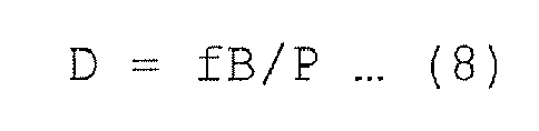
Fig. 6 , based on the predetermined pitch B of themarks 11 on the levelingrod 1, a focal point distance f of the objective lens, and the pitch P of themarks 11 formed as an image on theline sensor 24, which is determined from the frequency measurement, a distance D up to the levelingrod 1 is determined by the following formula. -
- When the frequency measurement is successful in Step S3, the process proceeds to Step S4, to perform a height measurement as described later. Next, it is checked whether or not the height measurement is successful. When the height measurement is successful, the process proceeds to Step S6, to indicate measured values of the height and distance, and the measurement program is terminated. When the height measurement fails, the process proceeds to Step S7, to indicate an error in height measurement, and the measurement program is terminated.
- The height measurement in Step S4 will be described in more detail by
Figs. 7 and8 . From Step S3, the process proceeds to Step S41, to measure the width dimensions of theblack marks 11. When themarks 11 are formed as an image on theline sensor 24 as shown inFig. 8A , an output signal from theline sensor 24 changes into one as inFig. 8B . Then, when the output signal from theline sensor 24 is differentiated, as shown inFig. 8C , falling pulses and rising pulses are detected. Therefore, it is possible to detect the width dimensions of therespective marks 11 according to intervals w of the both pulses. - Next, the process proceeds to Step S42, to perform an encoding process of converting the widths of the
respective marks 11 into integers (refer toFig. 2 ). Next, the process proceeds to Step S43, to search a corresponding place between a permutation obtained by converting the widths of therespective marks 11 into integers and the sequence stored in advance. Next, the process proceeds to Step S44 , to perform a height measurement when a corresponding place is found, and the process proceeds to the following Step S5. When a corresponding place is not found, themicrocomputer 3 stores that the height measurement fails, and the process similarly proceeds to the following Step S5. - In accordance with the thus described leveling
rod 1 and theelectronic level 2, because themarks 11 are arrayed at regular pitches, and the width dimensions of themarks 11 are changed, to obtain a permutation of integers, it is possible to measure a height h even in the case where one of themarks 11 is hidden by an obstacle or the like, to be unable to be detected. - Further, in the case where the distance between the
electronic level 2 and the levelingrod 1 is shorter than a predetermined distance, it is possible to reliably discriminate the width dimensions of all types of themarks 11. Therefore, it suffices that the number of themarks 11 to be retrieved in order to create a permutation of integers is small, which makes it possible to shorten the distance between the levelingrod 1 and theelectronic level 2 by that amount. - Further, in the case where the distance between the leveling
rod 1 and theelectronic level 2 is longer than the predetermined distance, at least two types of themarks 11 whose width dimensions are approximate to each other are discriminated as the same dimension, to be expressed as the same integer, thereby lengthening a distance by which it is possible to discriminate themarks 11. In this case, the types of integers corresponding to therespective marks 11 are decreased, and the number of themarks 11 necessary for specifying a collimation position is increased. Meanwhile, in the case where the distance between the levelingrod 1 and theelectronic level 2 is increased, the number of themarks 11 within the visual field of the collimating optical system is increased, and therefore, it is also possible to reliably perform a long distance measurement. - Moreover, because a permutation which is obtained by inverting a permutation retrieved from the
respective marks 11 as well is to differ from a permutation retrieved from any position of the aforementioned sequence (1), there is no corresponding place in the aforementioned sequence (1) in a permutation obtained in the case where the levelingrod 1 is in an upside-down state, and therefore, it is possible to judge that the levelingrod 1 may be set in an upside-down state. Then, when there is a corresponding portion in an inverted permutation in which the retrieved permutation is inverted in the opposite direction, it is judged that the levelingrod 1 is inverted, and the height is measured. - As is clear from the above-described description, the
electronic level 2 determines a permutation of integers based on the width dimensions of themarks 11, to determine a height of a collimation position, and is therefore hardly affected by a disturbance. Further, because the types of the integers composing a permutation are increased and decreased according to the length of the distance between the levelingrod 1 and theelectronic level 2, it is possible to expand a measurable range between the levelingrod 1 and theelectronic level 2. - Further, in the following
Patent Document 2 as well, there is disclosed an electronic level and a leveling rod which are capable of expanding a measurable range. However, because there is little relationship with this invention, descriptions thereof will be omitted. -
- Patent Document 1: Japanese Patent No.
3789625 - Patent Document 2: Japanese Patent No.
2838246 - In the
electronic level 2 disclosed in theaforementioned Patent Document 1, there is a problem that, because width dimensions of themarks 11 of a barcode are converted into integers, a dimensional specification of a barcode pattern, a focal point distance or a view angle of the objective optical system of theelectronic level 2, and an angle of field and a pixel size of theline sensor 24 are interdependent, and therefore, it is impossible to easily expand a measurable range to a longer distance or a shorter distance. This is because a new pattern rule of the barcode pattern, and an arithmetic processing program for recognizing this are required in order to expand the measurable range. - The present invention has been achieved in consideration of the above-described problem, and an object of the present invention is to be capable of easily expanding a measurable range, so as to measure the both of a long distance measurement and a short distance measurement, and not to perform an incorrect measurement even when a conventional leveling rod for electronic level is mixed and used.
- In order to solve the above-described problem, in accordance with a first aspect of the invention, a leveling rod for electronic level having a pattern forming a grayscale by arraying a plurality of bar-shapedmarks along a longitudinal direction at regular pitches, the leveling rod for electronic level has, as the pattern, a first pattern in which a grayscale is formed according to a predetermined rule for a measurement within a first distance range, and a second pattern which is enlarged or reduced with respect to a pattern in which the grayscale of the first pattern is inverted for a measurement within a second distance range different from the first distance range.
- In accordance with a second aspect of the invention, the leveling rod for electronic level according to the first aspect has a first surface and a second surface which differ in orientation, in which the first pattern is formed on the first surface, and the second pattern is formed on the second surface.
- In accordance with a third aspect of the invention, an electronic level including a line sensor which generates an output signal according to the first pattern or the second pattern formed on the leveling rod for electronic level according to the first or second aspect, and height measurement means for measuring a height of a collimation point from the output signal from the line sensor so as to correspond to the first pattern, the electronic level further includes grayscale inversion means for inverting the grayscale of the output signal from the line sensor in order to correspond to the secondpattern, and height correction means for correcting the height measured by the height measurement means according to a reduction scale of the second pattern with respect to the first pattern, and the electronic level is also capable of performing a height measurement by use of the leveling rod for electronic level according to the first or second aspect.
- In accordance with a fourth aspect of the invention, the electronic level according to the third aspect, further including remeasurement means for making the height measurement means perform a remeasurement after the correspondence to the first pattern is changed to the correspondence to the second pattern, or the correspondence to the second pattern is changed to the correspondence to the first pattern in a case where it is impossible to measure a height of a collimation point with the height measurement means.
- In accordance with a fifth aspect of the invention, the electronic level according to the fourth aspect, further including pattern storing means for storing whether it is possible to perform a height measurement with the first pattern or the second pattern, the electronic level performs a next first measurement so as to correspond to the stored pattern.
- In accordance with the first aspect of the invention, because the leveling rod for electronic level has the first pattern and the second pattern which is enlarged or reduced with respect to the pattern in which the grayscale of the first pattern is inverted, provided that the electronic level according to the third aspect of the invention is used, it is possible to perform a height measurement by use of either of the first pattern or the second pattern, and therefore, it is possible to perform a measurement within the first distance range by use of the first pattern, and it is possible to perform a measurement within the second distance range of a longer distance or a shorter distance than the first distance range by use of the second pattern, which makes it possible to easily expand the measurement range.
- In accordance with the second aspect of the invention, because the leveling rod for electronic level has the first surface and the second surface which differ in orientation, and the first pattern is formed on the first surface, and the second pattern is formed on the second surface, it is possible to expand the measurement range with the one leveling rod for electronic level, that is convenient.
- In accordance with the third aspect of the invention, because the electronic level includes the height measurement means for measuring a height of a collimation point from the output signal from the line sensor so as to correspond to the first pattern, provided that a measurement is performed by use of the first pattern, it is possible to perform the measurement in a conventional manner. When a measurement is performed by use of the second pattern, by inverting the grayscale of an output signal from the line sensor by the grayscale inversion means, it is possible to read a height from the second pattern with the height measurement means. However, because the second pattern is enlarged or reduced with respect to the first pattern, it is impossible to obtain an accurate height as it is. Then, when the grayscale of an output signal from the line sensor is inverted so as to correspond to the second pattern, a height measured by the height measurement means is corrected according to a reduction scale of the second pattern with respect to the first pattern, to be able to obtain a correct height. In this way, it is possible to perform a measurement within the first distance range by use of the first pattern, and a measurement within the second distance range of a longer distance or a shorter distance than the case where the first pattern is used is performed by use of the second pattern, thereby it is possible to easily expand the measurement range without changing the hardware of the electronic level. In addition, even when the conventional leveling rod for electronic level is mixed and used, an incorrect measurement is not caused.
- In accordance with the fourth aspect of the invention, because the electronic level further includes the remeasurement means for making the height measurement means perform a remeasurement after the correspondence to the first pattern is changed to the correspondence to the second pattern, or the correspondence to the second pattern is changed to the correspondence to the first pattern in a case where it is impossible to measure a height of a collimation point with the height measurement means, it is possible to automatically judge the first pattern or the second pattern, to be able to perform a measurement without giving a manual instruction to perform a measurement with the first pattern or the second pattern, that is convenient.
- In accordance with the fifth aspect of the invention, the electronic level further includes the pattern storing means for storing whether it is possible to perform a height measurement with the first pattern or the second pattern, and the electronic level performs a next first measurement so as to correspond to the stored pattern. Therefore, wasteful measurements are reduced, which makes it possible to promptly complete the measurement.
-
-
Fig. 1 is a diagram for explanation of the use of a conventional electronic level and a conventional leveling rod. -
Fig. 2 is a diagram for explanation of a barcode of the conventional leveling rod. -
Fig. 3 is a block diagram of the conventional electronic level. -
Fig. 4 is a diagram showing a state in which the leveling rod is collimated with the conventional electronic level. -
Fig. 5 is a flowchart of a measurement program for performing a height measurement with the conventional electronic level. -
Fig. 6 is a diagram for explanation of the principle of a distance measurement. -
Fig. 7 is a flowchart for detailed explanation of a part of the measurement program. -
Fig. 8 is a diagram for explanation of a method for detecting widths of marks with the conventional electronic level. -
Fig. 9 is a diagram for explanation of a leveling rod of an embodiment of the present invention. -
Fig. 10 is a flowchart for explanation of a measurement program provided in an electronic level according to the embodiment of the present invention. -
Fig. 11 is a diagram for explanation of a method for detecting widths of marks in which a grayscale is inverted in the aforementioned embodiment. -
Fig. 12 is a table in which the requirements in the case where grayscale inversion processing is performed in the aforementioned embodiment are tabularized. -
Fig. 13 is a table in which the requirements in the case where a remeasurement is performed in the aforementioned embodiment are tabularized. - Hereinafter, an electronic level and a leveling rod according to an embodiment of the present invention will be described with reference to the drawings. A leveling
rod 1 in the present embodiment has, as shown inFig. 9 , in addition to afirst pattern 1A which is a barcode pattern which is the same as that of the levelingrod 1 disclosed in theaforementioned Patent Document 1, asecond pattern 1B of a similar shape which is reduced with respect to one 1R in which the black and white (grayscale) of thefirst pattern 1A is inverted. The twopatterns leveling rod 1, or may be respectively drawn on the one surfaces of the two levelingrods 1, or may be respectively drawn on the first surface and the second surface, which differ in orientation, of the levelingrod 1 having polygonal sections. - On the other hand, an
electronic level 2 of the present embodiment is the same as theelectronic level 2 disclosed in theaforementioned Patent Document 1 except for the point that a measurement program by which it is possible to perform a height measurement from not only thefirst pattern 1A drawn on the levelingrod 1, but also from thesecond pattern 1B is provided. - Then, the measurement program performed by a
microcomputer 3 will be described. As shown inFig. 10 , when the measurement program is started, the process proceeds to Step S1, to acquire an output signal from aline sensor 24. Next, the process proceeds to Step S2, to perform a frequency measurement with respect to the acquired output signal. Next, the process proceeds to Step S3, and it is checked whether or not the frequency measurement is successful. Until this point, and when the frequency measurement fails, the process proceeds to Step S8, to indicate an error in distance measurement, and the measurement is terminated, which are the same as those disclosed in theaforementioned Patent Document 1. - When the frequency measurement is successful in Step S3, the process proceeds to Step S10, to initialize control variables J and K. The control variable J is to instruct a setting (setting which is the same as the conventional setting) for corresponding to the
first pattern 1A (J =1) or a setting for corresponding to thesecond pattern 1B (J = 2). In order to correspond to thesecond pattern 1B, after acquiring an output signal from theline sensor 24, the output signal from theline sensor 24 is inverted (refer to B' inFig. 11 ). Thereafter, provided that the inverted output signal is differentiated in the same way in a conventional manner (refer to C inFig. 11 ), it is possible to obtain the widths w of themarks 11. The control variable K is to give an instruction to perform a first measurement with respect to a certain measurement point (K = 1) and a remeasurement (K = 2). In Step S10, with respect to the control variable K, K = 1 is set, and with respect to the control variable J, as will be described later, thefirst pattern 1A (J = 1) or thesecond pattern 1B (J = 2) with which it is possible to perform a height measurement, is set. - Next, the process proceeds to Step S11, first, it is checked whether or not the
second pattern 1B (J = 2) is instructed. When thesecond pattern 1B (J = 2) is instructed, the process proceeds to Step S12, to perform processing of inverting the output signal from theline sensor 24, and thereafter, the process proceeds to Step S4, to perform a height measurement. This step S4 is the same as that of the conventional invention disclosed inPatent Document 1. When thefirst pattern 1A (J = 1) is indicated, the process directly proceeds to Step S4, to perform a height measurement. Here, Steps S10 to S12 are equivalent to the grayscale inversion means described in the third aspect, and Step S4 is equivalent to the height measurement means described in the third aspect. - After the height measurement is performed in Step S4, the process proceeds to Step S21, and it is checked whether or not the height measurement is successful. When the height measurement fails, the process proceeds to Step S22, and it is checked whether or not it is an error other than an encoding error. An encoding error means a failure in detecting the
marks 11, a failure in converting width dimensions of themarks 11 into integers, and that it is impossible to find a corresponding point between a permutation converted into integers and the sequence stored in advance. When it is an error other than an encoding error, the process proceeds to Step S7, to indicate an error in height measurement, and the process is terminated. When it is an encoding error, the process proceeds to Step S23, and it is checked whether or not the setting is a remeasurement (K = 2). When the setting is a remeasurement, the process proceeds to Step S7, to indicate an error in height measurement, and the process is terminated. When the setting is not a remeasurement (K = 1), the process proceeds to Step S24, to set a remeasurement (when K = 2, J =1, J =1 is changed to J = 2, when it is J = 2, J = 2 is changed to J = 1), and the process returns to Step S11. Here, Steps S21 to S24 are equivalent to the remeasurement means described in the fourth aspect. - When it is judged that the height measurement is successful in Step S21, the process proceeds to Step S31, and it is checked whether or not the setting of the measurement program corresponds to the
second pattern 1B (J = 2). Because thesecond pattern 1B is reduced with respect to thefirst pattern 1A, when the setting of the measurement program corresponds to thesecond pattern 1B (J = 2), the process proceeds to Step S32, to perform correction processing of a height measured in Step S4 according to a reduction scale of thesecond pattern 1B with respect to thefirst pattern 1A, to determine a correct height, and the process proceeds to Step S40. When the setting of the measurement program does not correspond to thesecond pattern 1B (J = 2), that is, when the setting of the measurement program corresponds to thefirst pattern 1A, the process directly proceeds to Step S40. Here, Steps S31 to S32 are equivalent to the height correction means described in the third aspect. - Then, the process proceeds to Step S40, to store a value of the control variable J. This is because the leveling
rod 1 is moved to an adjacent measurement point also in the next measurement, and therefore, the same pattern may be used inmanycases. Then, the process proceeds to Step S6, to indicate the measured result, and the process is terminated. Here, Step S40 is equivalent to the pattern storage means described in the fifth aspect. - In addition, in Table 12, it is tabularized that in what case an output signal from the
line sensor 24 is inverted, and in Table 13, it is tabularized that in what case a remeasurement is performed. - In accordance with the leveling
rod 1 and theelectronic level 2 of the present embodiment, provided that a measurement is performed by use of thefirst pattern 1A, it is possible to perform the measurement in a conventional manner. When a measurement is performed by use of thesecond pattern 1B, by inverting the grayscale of an output signal from theline sensor 24, it is possible to read a height from thesecond pattern 1B. However, because thesecond pattern 1B is reduced with respect to thefirst pattern 1A, it is impossible to obtain an accurate height as it is. Then, when thesecond pattern 1B is used, a height is made to be corrected according to a reduction scale of thesecond pattern 1B with respect to thefirst pattern 1A, to obtain a correct height. In this way, it is possible to perform a measurement within the first distance range by use of thefirst pattern 1A, and it is possible to easily perform a measurement of a shorter distance than the first distance range by use of thesecond pattern 1B. In addition, it is possible to not perform an incorrect measurement even when the conventional leveling rod is mixed and used. - Further, in a case where it is impossible to measure a height of a collimation point from an output signal from the
line sensor 24, the correspondence to thefirst pattern 1A is changed to the correspondence to thesecond pattern 1B, or the correspondence to thesecond pattern 1B is changed to the correspondence to thefirst pattern 1A, to make the electronic level perform a remeasurement. Therefore, it is possible to automatically judge thefirst pattern 1A or thesecond pattern 1B, to be able to perform a measurement without giving a manual instruction to perform a measurement with thefirst pattern 1A or thesecond pattern 1B, that is convenient. - Moreover, because it is storedwhether it is possible to perform the height measurement with the
first pattern 1A or thesecond pattern 1B, and the next first measurement is performed so as to correspond to the stored pattern, wasteful measurements are reduced, which makes it possible to promptly complete the measurement. - Meanwhile, the present invention is not limited to the embodiment, and various modifications are possible. Hereinafter, some modifications are shown.
- (1) In the aforementioned example, the pattern disclosed in the
aforementioned Patent Document 1 is adopted as a pattern drawn on the levelingrod 1. However, any of the patterns which are used as leveling rods for electronic level may be adopted when there is a means capable of discriminating a state in which the grayscale of the pattern is inverted. For example, the pattern disclosed in theaforementioned Patent Document 2 may be adopted. - (2) In the aforementioned example, the
second pattern 1B drawn on the levelingrod 1 has a similar shape which is reduced with respect to thepattern 1R in which the black and white (grayscale) of thefirst pattern 1A is inverted. However, thesecond pattern 1B may have a similar shape which is enlarged with respect to thepattern 1R in contrast. In this case, by use of thesecond pattern 1B, it is possible to perform a much longer distance measurement. Further, the levelingrod 1 may be a triangular prism shape, and thefirst pattern 1A may be drawn on the first surface, thesecond pattern 1B having a similar shape which is reduced with respect to thepattern 1R in which the black and white (grayscale) of thefirst pattern 1A is inverted may be drawn on the second surface, and a third pattern having a similar shape which is enlarged with respect to thepattern 1R in which the black and white (grayscale) of thefirst pattern 1A is inverted may be drawn on the third surface. - (3) In the measurement program in the aforementioned example, Step S40 may be omitted. In this case, J = 1 is set in Step S10. Then, in the first measurement, an output signal from the
line sensor 24 is directly used to perform a height measurement so as to correspond to thefirst pattern 1A (J = 1), and in the case where the height measurement fails, and a remeasurement is performed, an output signal from theline sensor 24 is inverted to perform a height measurement so as to correspond to thesecond pattern 1B (J = 2). - (4) In the measurement program in the aforementioned example, in Step S10, an operator may manually input the
first pattern 1A (J = 1) or thesecond pattern 1B (J = 2). In this case, as a matter of course, Step S40 may be omitted, and because the height measurement is not likely to fail, Steps S22 to S24 may be omitted. - (5) In the measurement program in the aforementioned example, it may be automatically determined to correspond to the
first pattern 1A (J = 1) or thesecond pattern 1B (J = 2) . For this, it is judged based on whether or not theblack marks 11 are aligned at regular pitches. When those are regular pitches, thefirst pattern 1A (J = 1) is set, and when those are not regular pitches, thesecond pattern 1B (J = 2) is set. In this case, Step S40 may be omitted, on the other hand, it is acceptable that Steps S22 to S24 may be left. -
- 1: Leveling rod
- 2: Electronic level
- 11: Marks
- 24: Line sensor
Claims (5)
- A leveling rod for electronic level having a pattern forming a grayscale by arraying a plurality of bar-shaped marks along a longitudinal direction at regular pitches, the leveling rod for electronic level has,
as the pattern, a first pattern in which a grayscale is formed according to a predetermined rule for a measurement within a first distance range, and a second pattern which is enlarged or reduced with respect to a pattern in which the grayscale of the first pattern is inverted for a measurement within a second distance range different from the first distance range. - The leveling rod for electronic level according to claim 1, has a first surface and a second surface which differ in orientation, and the first pattern is formed on the first surface, and the second pattern is formed on the second surface.
- An electronic level comprising: a line sensor which generates an output signal according to the first pattern or the second pattern formed on the leveling rod for electronic level according to claim 1 or claim 2; and height measurement means for measuring a height of a collimation point from the output signal from the line sensor so as to correspond to the first pattern, the electronic level further comprises
grayscale inversion means for inverting the grayscale of the output signal from the line sensor in order to correspond to the second pattern, and height correction means for correcting the height measured by the height measurement means according to a reduction scale of the second pattern with respect to the first pattern,
the electronic level is capable of performing a height measurement by use of the leveling rod for electronic level according to claim 1 or claim 2. - The electronic level according to claim 3 further comprising remeasurement means for making the height measurement means perform a remeasurement after the correspondence to the first pattern is changed to the correspondence to the second pattern, or the correspondence to the second pattern is changed to the correspondence to the first pattern in a case where it is impossible to measure a height of a collimation point with the height measurement means.
- The electronic level according to claim 4 further comprising pattern storing means for storing whether it is possible to perform a height measurement with the first pattern or the second pattern in the last measurement, the electronic level performs a next first measurement so as to correspond to the stored pattern.
Applications Claiming Priority (2)
| Application Number | Priority Date | Filing Date | Title |
|---|---|---|---|
| JP2010204346A JP5530873B2 (en) | 2010-09-13 | 2010-09-13 | Electronic level and scale for electronic level |
| PCT/JP2011/063551 WO2012035835A1 (en) | 2010-09-13 | 2011-06-14 | Electronic level and leveling rod for electronic level |
Publications (3)
| Publication Number | Publication Date |
|---|---|
| EP2618106A1 true EP2618106A1 (en) | 2013-07-24 |
| EP2618106A4 EP2618106A4 (en) | 2013-11-20 |
| EP2618106B1 EP2618106B1 (en) | 2014-11-05 |
Family
ID=45831317
Family Applications (1)
| Application Number | Title | Priority Date | Filing Date |
|---|---|---|---|
| EP11824847.5A Not-in-force EP2618106B1 (en) | 2010-09-13 | 2011-06-14 | Electronic level and leveling rod for electronic level |
Country Status (5)
| Country | Link |
|---|---|
| US (1) | US8510964B2 (en) |
| EP (1) | EP2618106B1 (en) |
| JP (1) | JP5530873B2 (en) |
| CN (1) | CN103038604B (en) |
| WO (1) | WO2012035835A1 (en) |
Families Citing this family (8)
| Publication number | Priority date | Publication date | Assignee | Title |
|---|---|---|---|---|
| JP5378259B2 (en) * | 2010-02-10 | 2013-12-25 | 株式会社 ソキア・トプコン | Electronic level |
| JP5829848B2 (en) * | 2011-07-04 | 2015-12-09 | 株式会社トプコン | Electronic level gauge |
| JP6189134B2 (en) * | 2013-08-08 | 2017-08-30 | 株式会社トプコン | Electronic level |
| US9443311B2 (en) | 2014-06-12 | 2016-09-13 | Topcon Positioning Systems, Inc. | Method and system to identify a position of a measurement pole |
| EP3408610A4 (en) * | 2016-01-25 | 2020-01-01 | Topcon Positioning Systems, Inc. | METHOD AND DEVICE FOR OPTICAL SINGLE CAMERA MEASUREMENTS |
| US10300573B2 (en) | 2017-05-24 | 2019-05-28 | Trimble Inc. | Measurement, layout, marking, firestop stick |
| US10341618B2 (en) | 2017-05-24 | 2019-07-02 | Trimble Inc. | Infrastructure positioning camera system |
| US20220390232A1 (en) * | 2020-12-12 | 2022-12-08 | Graham Procyk | Apparatus for use with a rotary laser level system |
Family Cites Families (10)
| Publication number | Priority date | Publication date | Assignee | Title |
|---|---|---|---|---|
| JPS59168116U (en) * | 1983-04-25 | 1984-11-10 | 松森 樹男 | Surveying staff |
| JPH0364441U (en) * | 1989-10-25 | 1991-06-24 | ||
| JP3141123B2 (en) * | 1992-05-23 | 2001-03-05 | 株式会社トプコン | Electronic level and staff for electronic level |
| JP3789625B2 (en) * | 1997-12-19 | 2006-06-28 | 株式会社ソキア | Electronic level gauge and electronic level |
| DE19826873C1 (en) * | 1998-06-17 | 1999-11-25 | Zeiss Carl Jena Gmbh | Digital levelling rod for use over wider range of distances |
| US6202314B1 (en) * | 1998-07-30 | 2001-03-20 | Chan Y. Park | Calibration system for use with measuring systems |
| JP2001091256A (en) * | 1999-09-21 | 2001-04-06 | Topcon Corp | Staff for leveling |
| EP1593935A1 (en) * | 2004-05-06 | 2005-11-09 | Leica Geosystems AG | Levelling rod, level determining apparatus for said rod and level determining method |
| US7373725B1 (en) * | 2005-10-20 | 2008-05-20 | Laserline Mfg., Inc. | Surveying systems and methods for detecting and measuring changes in elevation |
| US8864327B2 (en) * | 2011-01-28 | 2014-10-21 | Rm Asset Group, Llc | Illumination device for use with survey level rod and method of use |
-
2010
- 2010-09-13 JP JP2010204346A patent/JP5530873B2/en active Active
-
2011
- 2011-06-14 CN CN201180036987.7A patent/CN103038604B/en active Active
- 2011-06-14 EP EP11824847.5A patent/EP2618106B1/en not_active Not-in-force
- 2011-06-14 WO PCT/JP2011/063551 patent/WO2012035835A1/en not_active Ceased
- 2011-06-14 US US13/818,464 patent/US8510964B2/en active Active
Also Published As
| Publication number | Publication date |
|---|---|
| US20130152413A1 (en) | 2013-06-20 |
| JP2012058189A (en) | 2012-03-22 |
| CN103038604A (en) | 2013-04-10 |
| EP2618106A4 (en) | 2013-11-20 |
| US8510964B2 (en) | 2013-08-20 |
| WO2012035835A1 (en) | 2012-03-22 |
| CN103038604B (en) | 2014-01-01 |
| EP2618106B1 (en) | 2014-11-05 |
| JP5530873B2 (en) | 2014-06-25 |
Similar Documents
| Publication | Publication Date | Title |
|---|---|---|
| EP2618106B1 (en) | Electronic level and leveling rod for electronic level | |
| US4715714A (en) | Measuring device for determining relative position between two items | |
| US7644505B2 (en) | Levelling rod, level determining apparatus for said rod, and level determining method | |
| EP2543959B1 (en) | Surveying staff for electronic levelling instrument | |
| JP3789625B2 (en) | Electronic level gauge and electronic level | |
| US6907133B2 (en) | Automatic surveying system | |
| JP6614954B2 (en) | Crack width measuring device | |
| JP2001091255A (en) | Electronic level and electronic level focusing control method | |
| JP4648033B2 (en) | Surveyor autofocus mechanism | |
| JP3795190B2 (en) | Electronic level | |
| EP1593934A1 (en) | Levelling rod and level determination apparatus and method e.g. for geodetic applications | |
| EP2535683B1 (en) | Electronic level | |
| JP4884612B2 (en) | Surveyor equipped with an automatic character reading device | |
| JP4717278B2 (en) | Automatic scale scale reader | |
| Aldalil | A New Method for Measuring Leveling Heights Using Computer Vision Techniques | |
| JP4873922B2 (en) | Measure area detection method and apparatus | |
| JP5541799B2 (en) | Autofocus surveying instrument | |
| JPH0518042B2 (en) | ||
| JPH0456243B2 (en) | ||
| LT4966B (en) | Level |
Legal Events
| Date | Code | Title | Description |
|---|---|---|---|
| PUAI | Public reference made under article 153(3) epc to a published international application that has entered the european phase |
Free format text: ORIGINAL CODE: 0009012 |
|
| 17P | Request for examination filed |
Effective date: 20130312 |
|
| AK | Designated contracting states |
Kind code of ref document: A1 Designated state(s): AL AT BE BG CH CY CZ DE DK EE ES FI FR GB GR HR HU IE IS IT LI LT LU LV MC MK MT NL NO PL PT RO RS SE SI SK SM TR |
|
| A4 | Supplementary search report drawn up and despatched |
Effective date: 20131017 |
|
| RIC1 | Information provided on ipc code assigned before grant |
Ipc: G01C 15/06 20060101AFI20131011BHEP |
|
| DAX | Request for extension of the european patent (deleted) | ||
| GRAP | Despatch of communication of intention to grant a patent |
Free format text: ORIGINAL CODE: EPIDOSNIGR1 |
|
| INTG | Intention to grant announced |
Effective date: 20140521 |
|
| GRAS | Grant fee paid |
Free format text: ORIGINAL CODE: EPIDOSNIGR3 |
|
| GRAA | (expected) grant |
Free format text: ORIGINAL CODE: 0009210 |
|
| AK | Designated contracting states |
Kind code of ref document: B1 Designated state(s): AL AT BE BG CH CY CZ DE DK EE ES FI FR GB GR HR HU IE IS IT LI LT LU LV MC MK MT NL NO PL PT RO RS SE SI SK SM TR |
|
| REG | Reference to a national code |
Ref country code: GB Ref legal event code: FG4D |
|
| REG | Reference to a national code |
Ref country code: CH Ref legal event code: EP |
|
| REG | Reference to a national code |
Ref country code: AT Ref legal event code: REF Ref document number: 694861 Country of ref document: AT Kind code of ref document: T Effective date: 20141115 |
|
| REG | Reference to a national code |
Ref country code: IE Ref legal event code: FG4D |
|
| REG | Reference to a national code |
Ref country code: DE Ref legal event code: R096 Ref document number: 602011011210 Country of ref document: DE Effective date: 20141218 |
|
| REG | Reference to a national code |
Ref country code: CH Ref legal event code: NV Representative=s name: ISLER AND PEDRAZZINI AG, CH |
|
| REG | Reference to a national code |
Ref country code: SE Ref legal event code: TRGR |
|
| REG | Reference to a national code |
Ref country code: AT Ref legal event code: MK05 Ref document number: 694861 Country of ref document: AT Kind code of ref document: T Effective date: 20141105 |
|
| REG | Reference to a national code |
Ref country code: NL Ref legal event code: VDEP Effective date: 20141105 |
|
| REG | Reference to a national code |
Ref country code: LT Ref legal event code: MG4D |
|
| PG25 | Lapsed in a contracting state [announced via postgrant information from national office to epo] |
Ref country code: PT Free format text: LAPSE BECAUSE OF FAILURE TO SUBMIT A TRANSLATION OF THE DESCRIPTION OR TO PAY THE FEE WITHIN THE PRESCRIBED TIME-LIMIT Effective date: 20150305 Ref country code: ES Free format text: LAPSE BECAUSE OF FAILURE TO SUBMIT A TRANSLATION OF THE DESCRIPTION OR TO PAY THE FEE WITHIN THE PRESCRIBED TIME-LIMIT Effective date: 20141105 Ref country code: IS Free format text: LAPSE BECAUSE OF FAILURE TO SUBMIT A TRANSLATION OF THE DESCRIPTION OR TO PAY THE FEE WITHIN THE PRESCRIBED TIME-LIMIT Effective date: 20150305 Ref country code: NO Free format text: LAPSE BECAUSE OF FAILURE TO SUBMIT A TRANSLATION OF THE DESCRIPTION OR TO PAY THE FEE WITHIN THE PRESCRIBED TIME-LIMIT Effective date: 20150205 Ref country code: LT Free format text: LAPSE BECAUSE OF FAILURE TO SUBMIT A TRANSLATION OF THE DESCRIPTION OR TO PAY THE FEE WITHIN THE PRESCRIBED TIME-LIMIT Effective date: 20141105 Ref country code: NL Free format text: LAPSE BECAUSE OF FAILURE TO SUBMIT A TRANSLATION OF THE DESCRIPTION OR TO PAY THE FEE WITHIN THE PRESCRIBED TIME-LIMIT Effective date: 20141105 Ref country code: FI Free format text: LAPSE BECAUSE OF FAILURE TO SUBMIT A TRANSLATION OF THE DESCRIPTION OR TO PAY THE FEE WITHIN THE PRESCRIBED TIME-LIMIT Effective date: 20141105 |
|
| PG25 | Lapsed in a contracting state [announced via postgrant information from national office to epo] |
Ref country code: GR Free format text: LAPSE BECAUSE OF FAILURE TO SUBMIT A TRANSLATION OF THE DESCRIPTION OR TO PAY THE FEE WITHIN THE PRESCRIBED TIME-LIMIT Effective date: 20150206 Ref country code: RS Free format text: LAPSE BECAUSE OF FAILURE TO SUBMIT A TRANSLATION OF THE DESCRIPTION OR TO PAY THE FEE WITHIN THE PRESCRIBED TIME-LIMIT Effective date: 20141105 Ref country code: CY Free format text: LAPSE BECAUSE OF FAILURE TO SUBMIT A TRANSLATION OF THE DESCRIPTION OR TO PAY THE FEE WITHIN THE PRESCRIBED TIME-LIMIT Effective date: 20141105 Ref country code: HR Free format text: LAPSE BECAUSE OF FAILURE TO SUBMIT A TRANSLATION OF THE DESCRIPTION OR TO PAY THE FEE WITHIN THE PRESCRIBED TIME-LIMIT Effective date: 20141105 Ref country code: LV Free format text: LAPSE BECAUSE OF FAILURE TO SUBMIT A TRANSLATION OF THE DESCRIPTION OR TO PAY THE FEE WITHIN THE PRESCRIBED TIME-LIMIT Effective date: 20141105 Ref country code: PL Free format text: LAPSE BECAUSE OF FAILURE TO SUBMIT A TRANSLATION OF THE DESCRIPTION OR TO PAY THE FEE WITHIN THE PRESCRIBED TIME-LIMIT Effective date: 20141105 Ref country code: AT Free format text: LAPSE BECAUSE OF FAILURE TO SUBMIT A TRANSLATION OF THE DESCRIPTION OR TO PAY THE FEE WITHIN THE PRESCRIBED TIME-LIMIT Effective date: 20141105 |
|
| PG25 | Lapsed in a contracting state [announced via postgrant information from national office to epo] |
Ref country code: CZ Free format text: LAPSE BECAUSE OF FAILURE TO SUBMIT A TRANSLATION OF THE DESCRIPTION OR TO PAY THE FEE WITHIN THE PRESCRIBED TIME-LIMIT Effective date: 20141105 Ref country code: EE Free format text: LAPSE BECAUSE OF FAILURE TO SUBMIT A TRANSLATION OF THE DESCRIPTION OR TO PAY THE FEE WITHIN THE PRESCRIBED TIME-LIMIT Effective date: 20141105 Ref country code: DK Free format text: LAPSE BECAUSE OF FAILURE TO SUBMIT A TRANSLATION OF THE DESCRIPTION OR TO PAY THE FEE WITHIN THE PRESCRIBED TIME-LIMIT Effective date: 20141105 Ref country code: SK Free format text: LAPSE BECAUSE OF FAILURE TO SUBMIT A TRANSLATION OF THE DESCRIPTION OR TO PAY THE FEE WITHIN THE PRESCRIBED TIME-LIMIT Effective date: 20141105 |
|
| PGFP | Annual fee paid to national office [announced via postgrant information from national office to epo] |
Ref country code: SE Payment date: 20150623 Year of fee payment: 5 Ref country code: CH Payment date: 20150623 Year of fee payment: 5 |
|
| REG | Reference to a national code |
Ref country code: DE Ref legal event code: R097 Ref document number: 602011011210 Country of ref document: DE |
|
| PLBE | No opposition filed within time limit |
Free format text: ORIGINAL CODE: 0009261 |
|
| STAA | Information on the status of an ep patent application or granted ep patent |
Free format text: STATUS: NO OPPOSITION FILED WITHIN TIME LIMIT |
|
| 26N | No opposition filed |
Effective date: 20150806 |
|
| PGFP | Annual fee paid to national office [announced via postgrant information from national office to epo] |
Ref country code: DE Payment date: 20150824 Year of fee payment: 5 |
|
| PG25 | Lapsed in a contracting state [announced via postgrant information from national office to epo] |
Ref country code: IT Free format text: LAPSE BECAUSE OF FAILURE TO SUBMIT A TRANSLATION OF THE DESCRIPTION OR TO PAY THE FEE WITHIN THE PRESCRIBED TIME-LIMIT Effective date: 20141105 |
|
| PG25 | Lapsed in a contracting state [announced via postgrant information from national office to epo] |
Ref country code: MC Free format text: LAPSE BECAUSE OF FAILURE TO SUBMIT A TRANSLATION OF THE DESCRIPTION OR TO PAY THE FEE WITHIN THE PRESCRIBED TIME-LIMIT Effective date: 20141105 |
|
| GBPC | Gb: european patent ceased through non-payment of renewal fee |
Effective date: 20150614 |
|
| PG25 | Lapsed in a contracting state [announced via postgrant information from national office to epo] |
Ref country code: LU Free format text: LAPSE BECAUSE OF FAILURE TO SUBMIT A TRANSLATION OF THE DESCRIPTION OR TO PAY THE FEE WITHIN THE PRESCRIBED TIME-LIMIT Effective date: 20150614 Ref country code: SI Free format text: LAPSE BECAUSE OF FAILURE TO SUBMIT A TRANSLATION OF THE DESCRIPTION OR TO PAY THE FEE WITHIN THE PRESCRIBED TIME-LIMIT Effective date: 20141105 |
|
| REG | Reference to a national code |
Ref country code: IE Ref legal event code: MM4A |
|
| REG | Reference to a national code |
Ref country code: FR Ref legal event code: ST Effective date: 20160229 |
|
| PG25 | Lapsed in a contracting state [announced via postgrant information from national office to epo] |
Ref country code: GB Free format text: LAPSE BECAUSE OF NON-PAYMENT OF DUE FEES Effective date: 20150614 Ref country code: IE Free format text: LAPSE BECAUSE OF NON-PAYMENT OF DUE FEES Effective date: 20150614 |
|
| PG25 | Lapsed in a contracting state [announced via postgrant information from national office to epo] |
Ref country code: RO Free format text: LAPSE BECAUSE OF FAILURE TO SUBMIT A TRANSLATION OF THE DESCRIPTION OR TO PAY THE FEE WITHIN THE PRESCRIBED TIME-LIMIT Effective date: 20141105 Ref country code: FR Free format text: LAPSE BECAUSE OF NON-PAYMENT OF DUE FEES Effective date: 20150630 |
|
| PG25 | Lapsed in a contracting state [announced via postgrant information from national office to epo] |
Ref country code: MT Free format text: LAPSE BECAUSE OF FAILURE TO SUBMIT A TRANSLATION OF THE DESCRIPTION OR TO PAY THE FEE WITHIN THE PRESCRIBED TIME-LIMIT Effective date: 20141105 |
|
| REG | Reference to a national code |
Ref country code: DE Ref legal event code: R119 Ref document number: 602011011210 Country of ref document: DE |
|
| REG | Reference to a national code |
Ref country code: SE Ref legal event code: EUG Ref country code: CH Ref legal event code: PL |
|
| PG25 | Lapsed in a contracting state [announced via postgrant information from national office to epo] |
Ref country code: SE Free format text: LAPSE BECAUSE OF NON-PAYMENT OF DUE FEES Effective date: 20160615 |
|
| PG25 | Lapsed in a contracting state [announced via postgrant information from national office to epo] |
Ref country code: DE Free format text: LAPSE BECAUSE OF NON-PAYMENT OF DUE FEES Effective date: 20170103 Ref country code: LI Free format text: LAPSE BECAUSE OF NON-PAYMENT OF DUE FEES Effective date: 20160630 Ref country code: CH Free format text: LAPSE BECAUSE OF NON-PAYMENT OF DUE FEES Effective date: 20160630 |
|
| PG25 | Lapsed in a contracting state [announced via postgrant information from national office to epo] |
Ref country code: HU Free format text: LAPSE BECAUSE OF FAILURE TO SUBMIT A TRANSLATION OF THE DESCRIPTION OR TO PAY THE FEE WITHIN THE PRESCRIBED TIME-LIMIT; INVALID AB INITIO Effective date: 20110614 Ref country code: SM Free format text: LAPSE BECAUSE OF FAILURE TO SUBMIT A TRANSLATION OF THE DESCRIPTION OR TO PAY THE FEE WITHIN THE PRESCRIBED TIME-LIMIT Effective date: 20141105 Ref country code: BG Free format text: LAPSE BECAUSE OF FAILURE TO SUBMIT A TRANSLATION OF THE DESCRIPTION OR TO PAY THE FEE WITHIN THE PRESCRIBED TIME-LIMIT Effective date: 20141105 |
|
| PG25 | Lapsed in a contracting state [announced via postgrant information from national office to epo] |
Ref country code: TR Free format text: LAPSE BECAUSE OF FAILURE TO SUBMIT A TRANSLATION OF THE DESCRIPTION OR TO PAY THE FEE WITHIN THE PRESCRIBED TIME-LIMIT Effective date: 20141105 |
|
| PG25 | Lapsed in a contracting state [announced via postgrant information from national office to epo] |
Ref country code: BE Free format text: LAPSE BECAUSE OF FAILURE TO SUBMIT A TRANSLATION OF THE DESCRIPTION OR TO PAY THE FEE WITHIN THE PRESCRIBED TIME-LIMIT Effective date: 20141105 |
|
| PG25 | Lapsed in a contracting state [announced via postgrant information from national office to epo] |
Ref country code: MK Free format text: LAPSE BECAUSE OF FAILURE TO SUBMIT A TRANSLATION OF THE DESCRIPTION OR TO PAY THE FEE WITHIN THE PRESCRIBED TIME-LIMIT Effective date: 20141105 |
|
| PG25 | Lapsed in a contracting state [announced via postgrant information from national office to epo] |
Ref country code: AL Free format text: LAPSE BECAUSE OF FAILURE TO SUBMIT A TRANSLATION OF THE DESCRIPTION OR TO PAY THE FEE WITHIN THE PRESCRIBED TIME-LIMIT Effective date: 20141105 |