EP2618091A1 - Refrigerant guiding pipe and heat exchanger having it - Google Patents
Refrigerant guiding pipe and heat exchanger having it Download PDFInfo
- Publication number
- EP2618091A1 EP2618091A1 EP11824507.5A EP11824507A EP2618091A1 EP 2618091 A1 EP2618091 A1 EP 2618091A1 EP 11824507 A EP11824507 A EP 11824507A EP 2618091 A1 EP2618091 A1 EP 2618091A1
- Authority
- EP
- European Patent Office
- Prior art keywords
- refrigerant guiding
- refrigerant
- guiding pipe
- pipe
- axial direction
- Prior art date
- Legal status (The legal status is an assumption and is not a legal conclusion. Google has not performed a legal analysis and makes no representation as to the accuracy of the status listed.)
- Withdrawn
Links
Images



Classifications
-
- F—MECHANICAL ENGINEERING; LIGHTING; HEATING; WEAPONS; BLASTING
- F28—HEAT EXCHANGE IN GENERAL
- F28F—DETAILS OF HEAT-EXCHANGE AND HEAT-TRANSFER APPARATUS, OF GENERAL APPLICATION
- F28F1/00—Tubular elements; Assemblies of tubular elements
-
- F—MECHANICAL ENGINEERING; LIGHTING; HEATING; WEAPONS; BLASTING
- F25—REFRIGERATION OR COOLING; COMBINED HEATING AND REFRIGERATION SYSTEMS; HEAT PUMP SYSTEMS; MANUFACTURE OR STORAGE OF ICE; LIQUEFACTION SOLIDIFICATION OF GASES
- F25B—REFRIGERATION MACHINES, PLANTS OR SYSTEMS; COMBINED HEATING AND REFRIGERATION SYSTEMS; HEAT PUMP SYSTEMS
- F25B39/00—Evaporators; Condensers
-
- F—MECHANICAL ENGINEERING; LIGHTING; HEATING; WEAPONS; BLASTING
- F28—HEAT EXCHANGE IN GENERAL
- F28F—DETAILS OF HEAT-EXCHANGE AND HEAT-TRANSFER APPARATUS, OF GENERAL APPLICATION
- F28F9/00—Casings; Header boxes; Auxiliary supports for elements; Auxiliary members within casings
- F28F9/02—Header boxes; End plates
- F28F9/026—Header boxes; End plates with static flow control means, e.g. with means for uniformly distributing heat exchange media into conduits
- F28F9/027—Header boxes; End plates with static flow control means, e.g. with means for uniformly distributing heat exchange media into conduits in the form of distribution pipes
- F28F9/0273—Header boxes; End plates with static flow control means, e.g. with means for uniformly distributing heat exchange media into conduits in the form of distribution pipes with multiple holes
-
- F—MECHANICAL ENGINEERING; LIGHTING; HEATING; WEAPONS; BLASTING
- F25—REFRIGERATION OR COOLING; COMBINED HEATING AND REFRIGERATION SYSTEMS; HEAT PUMP SYSTEMS; MANUFACTURE OR STORAGE OF ICE; LIQUEFACTION SOLIDIFICATION OF GASES
- F25B—REFRIGERATION MACHINES, PLANTS OR SYSTEMS; COMBINED HEATING AND REFRIGERATION SYSTEMS; HEAT PUMP SYSTEMS
- F25B2500/00—Problems to be solved
- F25B2500/01—Geometry problems, e.g. for reducing size
-
- F—MECHANICAL ENGINEERING; LIGHTING; HEATING; WEAPONS; BLASTING
- F25—REFRIGERATION OR COOLING; COMBINED HEATING AND REFRIGERATION SYSTEMS; HEAT PUMP SYSTEMS; MANUFACTURE OR STORAGE OF ICE; LIQUEFACTION SOLIDIFICATION OF GASES
- F25B—REFRIGERATION MACHINES, PLANTS OR SYSTEMS; COMBINED HEATING AND REFRIGERATION SYSTEMS; HEAT PUMP SYSTEMS
- F25B39/00—Evaporators; Condensers
- F25B39/02—Evaporators
- F25B39/028—Evaporators having distributing means
-
- F—MECHANICAL ENGINEERING; LIGHTING; HEATING; WEAPONS; BLASTING
- F28—HEAT EXCHANGE IN GENERAL
- F28D—HEAT-EXCHANGE APPARATUS, NOT PROVIDED FOR IN ANOTHER SUBCLASS, IN WHICH THE HEAT-EXCHANGE MEDIA DO NOT COME INTO DIRECT CONTACT
- F28D1/00—Heat-exchange apparatus having stationary conduit assemblies for one heat-exchange medium only, the media being in contact with different sides of the conduit wall, in which the other heat-exchange medium is a large body of fluid, e.g. domestic or motor car radiators
- F28D1/02—Heat-exchange apparatus having stationary conduit assemblies for one heat-exchange medium only, the media being in contact with different sides of the conduit wall, in which the other heat-exchange medium is a large body of fluid, e.g. domestic or motor car radiators with heat-exchange conduits immersed in the body of fluid
- F28D1/04—Heat-exchange apparatus having stationary conduit assemblies for one heat-exchange medium only, the media being in contact with different sides of the conduit wall, in which the other heat-exchange medium is a large body of fluid, e.g. domestic or motor car radiators with heat-exchange conduits immersed in the body of fluid with tubular conduits
- F28D1/053—Heat-exchange apparatus having stationary conduit assemblies for one heat-exchange medium only, the media being in contact with different sides of the conduit wall, in which the other heat-exchange medium is a large body of fluid, e.g. domestic or motor car radiators with heat-exchange conduits immersed in the body of fluid with tubular conduits the conduits being straight
- F28D1/05316—Assemblies of conduits connected to common headers, e.g. core type radiators
-
- F—MECHANICAL ENGINEERING; LIGHTING; HEATING; WEAPONS; BLASTING
- F28—HEAT EXCHANGE IN GENERAL
- F28D—HEAT-EXCHANGE APPARATUS, NOT PROVIDED FOR IN ANOTHER SUBCLASS, IN WHICH THE HEAT-EXCHANGE MEDIA DO NOT COME INTO DIRECT CONTACT
- F28D1/00—Heat-exchange apparatus having stationary conduit assemblies for one heat-exchange medium only, the media being in contact with different sides of the conduit wall, in which the other heat-exchange medium is a large body of fluid, e.g. domestic or motor car radiators
- F28D1/02—Heat-exchange apparatus having stationary conduit assemblies for one heat-exchange medium only, the media being in contact with different sides of the conduit wall, in which the other heat-exchange medium is a large body of fluid, e.g. domestic or motor car radiators with heat-exchange conduits immersed in the body of fluid
- F28D1/04—Heat-exchange apparatus having stationary conduit assemblies for one heat-exchange medium only, the media being in contact with different sides of the conduit wall, in which the other heat-exchange medium is a large body of fluid, e.g. domestic or motor car radiators with heat-exchange conduits immersed in the body of fluid with tubular conduits
- F28D1/053—Heat-exchange apparatus having stationary conduit assemblies for one heat-exchange medium only, the media being in contact with different sides of the conduit wall, in which the other heat-exchange medium is a large body of fluid, e.g. domestic or motor car radiators with heat-exchange conduits immersed in the body of fluid with tubular conduits the conduits being straight
- F28D1/0535—Heat-exchange apparatus having stationary conduit assemblies for one heat-exchange medium only, the media being in contact with different sides of the conduit wall, in which the other heat-exchange medium is a large body of fluid, e.g. domestic or motor car radiators with heat-exchange conduits immersed in the body of fluid with tubular conduits the conduits being straight the conduits having a non-circular cross-section
- F28D1/05366—Assemblies of conduits connected to common headers, e.g. core type radiators
-
- F—MECHANICAL ENGINEERING; LIGHTING; HEATING; WEAPONS; BLASTING
- F28—HEAT EXCHANGE IN GENERAL
- F28F—DETAILS OF HEAT-EXCHANGE AND HEAT-TRANSFER APPARATUS, OF GENERAL APPLICATION
- F28F1/00—Tubular elements; Assemblies of tubular elements
- F28F1/10—Tubular elements and assemblies thereof with means for increasing heat-transfer area, e.g. with fins, with projections, with recesses
- F28F1/12—Tubular elements and assemblies thereof with means for increasing heat-transfer area, e.g. with fins, with projections, with recesses the means being only outside the tubular element
- F28F1/126—Tubular elements and assemblies thereof with means for increasing heat-transfer area, e.g. with fins, with projections, with recesses the means being only outside the tubular element consisting of zig-zag shaped fins
Definitions
- the present invention relates to a refrigerant guiding pipe and a heat exchanger having the refrigerant guiding pipe.
- At least one of inlet and outlet manifolds of a typical heat exchanger is provided with a refrigerant guiding pipe, and the refrigerant guiding pipe is used as a distributer in the inlet manifold and as a collector in the outlet manifold.
- the refrigerant guiding pipe comprises a plurality of substantially circular openings arranged along a length of the refrigerant guiding pipe, and each of the openings has a center line directed substantially in a radial direction of the refrigerant guiding pipe.
- the refrigerant guiding pipe has an axial direction perpendicular to the center line of each of the openings. Therefore, resistance to refrigerant jetted through the openings is large, a great pressure drop is generated and distribution of refrigerant is adversely affected.
- the object of the present invention is to provide a refrigerant guiding pipe and a heat exchanger with the refrigerant guiding pipe which can improve uniformity of refrigerant distribution.
- the present invention provides a refrigerant guiding pipe.
- the refrigerant guiding pipe comprises a pipe wall in which an inner chamber is formed; an opening formed in the pipe wall; and a refrigerant guiding wall portion, at least a part of the refrigerant guiding wall portion being disposed to be substantially inclined with respect to an axial direction of the refrigerant guiding pipe to guide refrigerant passing through the opening.
- the refrigerant guiding wall portion is a recessed wall section depressed towards the inner chamber.
- At least a part of an edge of the refrigerant guiding wall portion is separated from the pipe wall, thereby forming the opening.
- At least a middle portion of the refrigerant guiding wall portion in a direction perpendicular to the axial direction of the refrigerant guiding pipe is positioned at an angle of more than zero degree and less than 90 degrees, preferably from about 5 degrees to about 75 degrees, with respect to the axial direction of the refrigerant guiding pipe; at least a portion of the refrigerant guiding wall portion is positioned at an angle of more than zero degree and less than 90 degrees, preferably from about 5 degrees to about 75 degrees, with respect to the axial direction of the refrigerant guiding pipe; or the refrigerant guiding wall portion is positioned at an angle of more than zero degree and less than 90 degrees, preferably from about 5 degrees to about 75 degrees, with respect to the axial direction of the refrigerant guiding pipe.
- At least the middle portion of the refrigerant guiding wall portion in the direction perpendicular to the axial direction of the refrigerant guiding pipe has a section along the axial direction of the refrigerant guiding pipe, and the section is composed of a plurality of substantially straight line-shaped segments or has substantially a shape of a curve; or the refrigerant guiding wall portion has a section along the axial direction of the refrigerant guiding pipe, and the section is composed of a plurality of substantially straight line-shaped segments or has substantially a shape of a curve.
- At least a first end of the recessed wall section in the axial direction of the refrigerant guiding pipe is separated from the pipe wall, thereby forming the opening.
- At least the middle portion of the recessed wall section in the direction perpendicular to the axial direction of the refrigerant guiding pipe is inclined with respect to the axial direction of the refrigerant guiding pipe, at least a portion of the refrigerant guiding wall is inclined with respect to the axial direction of the refrigerant guiding pipe, or the recessed wall section is inclined with respect to the axial direction of the refrigerant guiding pipe, and the first end of the recessed wall section is closer to an axis of the refrigerant guiding pipe than a second end of the recessed wall portion opposite to the first end.
- At least the middle portion of the recessed wall portion in the direction perpendicular to the axial direction of the refrigerant guiding pipe has a section along the axial direction of the refrigerant guiding pipe, and the section has a shape of a substantially straight line or is substantially straight; or the recessed wall portion has a section along the axial direction of the refrigerant guiding pipe, and the section has a shape of a substantially straight line or is substantially straight.
- At least the middle portion of the recessed wall section in the direction perpendicular to the axial direction of the refrigerant guiding pipe is positioned at an angle of more than zero degree and less than 90 degrees with respect to the axial direction of the refrigerant guiding pipe, or the recessed wall section is positioned at an angle of more than zero degree and less than 90 degrees with respect to the axial direction of the refrigerant guiding pipe.
- At least the middle portion of the recessed wall section in the direction perpendicular to the axial direction of the refrigerant guiding pipe has a section along the axial direction of the refrigerant guiding pipe, and the section is composed of a plurality of substantially straight line-shaped segments or has substantially a shape of a curve; or the recessed wall section has a section along the axial direction of the refrigerant guiding pipe, and the section is composed of a plurality of substantially straight line-shaped segments or has substantially a shape of a curve.
- the present invention provides a heat exchanger with the above refrigerant guiding pipe.
- refrigerant flows through the opening obliquely with respect to the axial direction of the refrigerant guiding pipe, thereby reducing resistance loss and improving uniformity of refrigerant distribution.
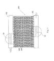
- a heat exchanger 100 comprises a first manifold 102; a second manifold 101 spaced away from the first manifold 102 by a predetermined distance; a heat exchange tube 103 such as a flat tube having two ends respectively connected with the first manifold 102 and the second manifold 101 so that a refrigerant channel in the heat exchange tube 103 is in communication with the first manifold 102 and the second manifold 101; a fin 104; and a refrigerant guiding pipe 10, at least one of the first manifold 102 and the second manifold 101 being provided with the refrigerant guiding pipe 10 therein.
- the heat exchanger may be any appropriate heat exchanger such as a heat exchanger with one row of core or a plurality of rows of cores or a heat exchanger with one or a plurality of loops.
- the heat exchanger may be a micro-channel heat exchanger.
- the refrigerant guiding pipe may be applied to an inner chamber part of an inlet manifold of a plurality of loops of the micro-channel heat exchanger and an inner chamber part of a manifold between the plurality of loops to guide and distribute two-phase refrigerant.
- FIGS. 2 and 3 show a refrigerant guiding pipe 10 according to a first embodiment of the present invention.
- the refrigerant guiding pipe 10 according to the first embodiment of the present invention comprises: a pipe wall 17 in which an inner chamber 19 is formed; an opening 11b formed in the pipe wall; and a refrigerant guiding wall portion, at least a part of the refrigerant guiding wall is disposed to be substantially inclined with respect to an axial direction of the refrigerant guiding pipe to guide refrigerant passing through the opening 11b. At least a part of an edge of the refrigerant guiding wall portion is separated from the pipe wall 17, thereby forming the opening.
- the refrigerant guiding wall portion is disposed so that a direction of refrigerant flow flowing through the opening 11b is substantially inclined with respect to the axial direction of the refrigerant guiding pipe 10.
- at least a part of the refrigerant guiding wall portion is positioned at an angle of more than zero degree and less than 90 degrees, preferably from about 5 degrees to about 75 degrees, with respect to the the axial direction of the refrigerant guiding pipe.
- the refrigerant guiding wall portion is disposed such that refrigerant flow flowing through the opening 11b is inclined with respect to the axial direction of the refrigerant guiding pipe by an angle of more than zero degree and less than 90 degrees, preferably from about 5 degrees to about 75 degrees.
- the refrigerant guiding pipe 10 has an open end and another end which may be closed or open.
- the refrigerant guiding pipe 10 further comprises a recessed wall section 23 depressed towards the inner chamber 19.
- a first end 231 of the recessed wall section 23 in the axial direction of the refrigerant guiding pipe is separated from the pipe wall 17, thereby forming the opening 11b.
- the recessed wall section 23 constitutes an example of the refrigerant guiding wall portion.
- the middle portion 23a extends from the first end 231 to the second end 232 in the axial direction of the refrigerant guiding pipe 10.
- a method of forming the opening 11b is to cut a notch with a certain depth in a pipe wall of a circular pipe for forming the refrigerant guiding pipe in a cutting direction perpendicular to the axial direction of the circular pipe, and then to press the pipe wall of the circular pipe on one side of the notch in the axial direction to depress the pipe wall.
- the opening 11b and the recessed wall section 23 are thereby formed.
- An orientation of the notch is determined by two directions, one of which is a depth direction of the notch (i.e., a direction of the notch in depth) directed in a radial direction of the circular pipe (upward and downward directions in FIG.
- the depth direction of the notch may be positioned at an angle of less than 90 degrees with respect to the radial direction of the circular pipe, and the cutting direction of the notch may be positioned at an angle of less than 90 degrees with respect to the axial direction of the circular pipe.
- the notch may be any notch in any appropriate orientation.
- a circumferential length of the notch i.e., a length of a circular arc of a separated segment 12 at which the first end 231 is separated from the pipe wall, is L, and a distance or pitch between the adjacent openings is d1.
- At least the middle portion 23a of the recessed wall section 23 in the direction perpendicular to the axial direction of the refrigerant guiding pipe 10 has a section along the axial direction of the refrigerant guiding pipe, the section has a shape of a substantially straight line or is substantially straight, and at least the middle portion 23a of the recessed wall section 23 in the direction perpendicular to the axial direction of the refrigerant guiding pipe is inclined at an angle ⁇ with respect to the axial direction of the refrigerant guiding pipe 10.
- the recessed wall section 23 has a section along the axial direction of the refrigerant guiding pipe, the section has a shape of a substantially straight line or is substantially straight, and the recessed wall section 23 is inclined at an angle ⁇ with respect to the axial direction of the refrigerant guiding pipe 10.
- At least the middle portion 23a of the recessed wall section 23 in the direction perpendicular to the axial direction of the refrigerant guiding pipe is positioned at an angle ⁇ of more than zero degree and less than 90 degrees, preferably from about 5 degrees to about 75 degrees, with respect to the axial direction of the refrigerant guiding pipe 10; or the recessed wall section 23 is positioned at an angle ⁇ of more than zero degree and less than 90 degrees, preferably from about 5 degrees to about 75 degrees, with respect to the axial direction of the refrigerant guiding pipe 10.
- the refrigerant guiding pipe 10 with the above configuration may also serve as a collector in the outlet manifold 101.
- the end 31 of the refrigerant guiding pipe 10 may be connected to a refrigerant piping but the other end 33 may not be connected to the refrigerant piping, or the other end 33 of the refrigerant guiding pipe 10 may be connected to a refrigerant piping but the end 31 may not be connected to the refrigerant piping.
- a row of the openings 11b or a plurality of rows of the openings 11b such as two or three rows of the openings 11b are disposed along the axial direction of the refrigerant guiding pipe 10.
- Another method of forming the opening 11b is to form the opening 11b and the recessed wall section 23 by pressing.
- the refrigerant guiding pipe 10 is formed with a pipe having a circular cross-section.
- the refrigerant guiding pipe 10 may also be formed of a pipe having any other cross section such as an elliptical or rectangular cross section.
- the refrigerant guiding pipe 10 may be formed of a pipe having a varying radius.
- the refrigerant guiding pipe 10 may be formed of any appropriate pipe known in the art.
- refrigerant flows along the inner chamber of the refrigerant guiding pipe, and the recessed wall section 23 mainly functions to guide the refrigerant.
- the refrigerant is ejected to an inner cavity of the manifold along a surface of the recessed wall section 23 so that resistance loss is low.
- a part of the refrigerant can be ejected directly into inner chambers of flat tubes 103 and the remaining refrigerant rushes to an end of the manifold 102 and then flows reversely so that refrigerant is uniformly distributed to the remaining flat tubes 103.
- Refrigerant is mixed in the manifold 102 so that gaseous refrigerant and liquid refrigerant are uniformly mixed and do not layer.
- FIGS. 4 and 5 show schematic views of a refrigerant guiding pipe 10 according to a second embodiment of the present invention.
- the refrigerant guiding pipe 10 according to the second embodiment may be the same as the refrigerant guiding pipe 10 according to the first embodiment except the following contents.
- the middle portion 23a of the recessed wall section 23 in the direction perpendicular to the axial direction of the refrigerant guiding pipe 10 has a section along the axial direction of the refrigerant guiding pipe 10, and the section is composed of a plurality of substantially straight line-shaped segments or a plurality of substantially straight segments; or the recessed wall section 23 has a section along the axial direction of the refrigerant guiding pipe 10, and the section is composed of a plurality of substantially straight line-shaped segments or a plurality of substantially straight segments.
- the middle portion 23a extends from the first end 231 to the second end 232 in the axial direction of the refrigerant guiding pipe 10.
- at least the middle portion 23a of the recessed wall section 23 in the direction perpendicular to the axial direction of the refrigerant guiding pipe 10 has a section along the axial direction of the refrigerant guiding pipe 10, and the section is composed of an arc-like segment; or the recessed wall section 23 has a section along the axial direction of the refrigerant guiding pipe 10, and the section is composed of an arc-like segment.
- the middle portion 23a of the recessed wall section 23 in the direction perpendicular to the axial direction of the refrigerant guiding pipe 10 has a section along the axial direction of the refrigerant guiding pipe 10, and the section has substantially a shape of a curve or arc, or is substantially curved; or the recessed wall section 23 has a section along the axial direction of the refrigerant guiding pipe 10, and the section has substantially a shape of a curve or arc, or is substantially curved.
- the middle portion 23a extends from the first end 231 to the second end 232 in the axial direction of the refrigerant guiding pipe 10.
- FIGS. 6a and 6b show a refrigerant guiding pipe 10 according to a third embodiment of the present invention.
- the structure of the refrigerant guiding pipe 10 according to the third embodiment may be substantially the same as that of the refrigerant guiding pipe 10 according to any one of the first and second embodiments except the parts described below.
- the recessed wall section 23 is substantially triangular in shape, and the triangular recessed wall section 23 has a base connected with the pipe wall 17, and the other edges of the triangular recessed wall section 23 are separated from the pipe wall 17.
- the entire recessed wall section 23 may be located substantially in one plane. In other words, the entire recessed wall section 23 may has a shape of a substantially flat plate.
- FIGS. 7a and 7b show a refrigerant guiding pipe 10 according to a fourth embodiment of the present invention.
- the structure of the refrigerant guiding pipe 10 according to the fourth embodiment may be substantially the same as that of the refrigerant guiding pipe 10 according to any one of the first through third embodiments except the parts described below.
- the recessed wall section 23 is substantially arcuate in shape, and the arcuate recessed wall section 23 has a straight edge connected with the pipe wall 17, and the other edges of the recessed wall section 23 are separated from the pipe wall 17.
- the entire recessed wall section 23 may be located substantially in one plane. In other words, the entire recessed wall section 23 may has a shape of a substantially flat plate.
- FIGS. 8a and 8b show a refrigerant guiding pipe 10 according to a fifth embodiment of the present invention.
- the structure of the refrigerant guiding pipe 10 according to the fifth embodiment may be substantially the same as that of the refrigerant guiding pipe 10 according to any one of the first through third embodiments except the parts described below.
- the recessed wall section 23 has substantially a shape of an arch, and except the first end 231 is separated from the pipe wall 17, the other edges of the recessed wall section 23 are connected with the pipe wall 17.
- the middle portion 23a of the refrigerant guiding wall portion in the direction perpendicular to the axial direction of the refrigerant guiding pipe 10 has a section along the axial direction of the refrigerant guiding pipe 10, and the section is composed of a plurality of substantially straight line-shaped segments or a plurality of substantially straight segments, or the section has substantially a shape of a curve or arc or is substantially curved; or the refrigerant guiding wall portion has a section along the axial direction of the refrigerant guiding pipe 10, and the section is composed of a plurality of substantially straight line-shaped segments or a plurality of substantially straight segments, or the section has substantially a shape of a curve or arc or is substantially curved.
- the middle portion 23a extends from the first end 231 to the second end 232 in the axial direction of the refrigerant guiding pipe 10.
- At least the middle portion 23a of the refrigerant guiding wall portion in the direction perpendicular to the axial direction of the refrigerant guiding pipe 10 has a section along the axial direction of the refrigerant guiding pipe 10, and the section comprises at least one of both at least one substantially straight line-shaped segment and at least one substantially curve-shaped segment; or the refrigerant guiding wall portion has a section along the axial direction of the refrigerant guiding pipe, and the section comprises at least one of both at least one substantially straight line-shaped segment and at least one substantially curve-shaped segment.
- At least the first end 231 is separated from the pipe wall 17.
- at least a part of the edge of the recessed wall section 23 is separated from the pipe wall 17.
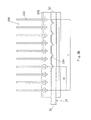
- FIGS. 9a , 9b and 10 are partially enlarged schematic views of a heat exchanger 100 according to the present invention.
- the refrigerant guiding pipe 10 may be provided with the openings 11b.
- the refrigerant guiding pipe 10 when the refrigerant guiding pipe 10 serves as a distributor in the inlet manifold 102, the refrigerant guiding pipe 10 is not provided with the opening 11b in a non-opening range from an inlet-side end 31 of the refrigerant guiding pipe 10 to a position spaced away from the end 31 in a direction extending from the inlet-side end 31 to another end 33 of the refrigerant guiding pipe 10.
- a number of the heat exchange tubes 103 such as flat tubes in the non-opening range is N
- a number of the heat exchange tubes 103 over a range corresponding to all of the heat exchange tubes 103 is T
- a ratio of the number N to the number T is more than 20% and less than 99%.
- a good refrigerant distribution effect can be obtained with the ratio. It is manifested by test that when the ratio is more than 95% and less than 99%, a very notable effect of uniformly distributing refrigerant can be obtained.
- the refrigerant guiding pipe 10 with the above configuration may also serve as a collector in the outlet manifold 101 to achieve an effect of uniformly distributing refrigerant.
- the end 31 of the refrigerant guiding pipe 10 will be connected to a refrigerant piping but the other end 33 will not be connected to the refrigerant piping.
- the refrigerant guiding pipe 10 may be designed in such a way that the number of the heat exchange tubes 103 such as flat tubes is N in the non-opening range from the end 31 of the refrigerant guiding pipe 10 to be connected with a refrigerant piping to a position spaced away from the end 31 by a predetermined distance, the number of the heat exchange tubes 103 over a range of the refrigerant guiding pipe 10 corresponding to all of the heat exchange tubes 103 is T, and a ratio of the number N to the number T is more than about 20% and less than about 99%, preferably more than about 95% and less than about 99%.
- the other end 33 of the refrigerant guiding pipe 10 is sealed by means of an element 35.
- the element 35 may not be disposed, and the other end 33 of the refrigerant guiding pipe 10 is open, thereby obtaining a very notable effect of uniformly distributing refrigerant.
- the refrigerant guiding pipe 10 with the above configuration may also serve as a collector in the outlet manifold 101 to achieve an effect of uniformly distributing refrigerant.
- Two-phase refrigerant in the refrigerant guiding pipe 10 is ejected from the openings 11b, and a part of the two-phase refrigerant enters directly into inner chambers of the heat exchange tubes 103 such as flat tubes so as to avoid excess amount of liquid refrigerant from entering into the heat exchange tubes 103 such as flat tubes.
- the remaining refrigerant rushes to an end of the manifold 102 and then flows reversely to be distributed to the heat exchange tubes 103 such as flat tubes uniformly.
- the refrigerant guiding pipe 10 and the heat exchange tubes 103 are opposite to each other, or a center line 13 of the refrigerant guiding pipe 10 intersects elongation lines of axes 105 of the heat exchange tubes 103 such as flat tubes.
- the refrigerant guiding pipe 10 and the heat exchange tubes 103 may be positioned in any appropriate relative positions.
- a center line 14 (for example, an axis 13 of the channel) of the opening 11b substantially perpendicular to the axial direction of the refrigerant guiding pipe 10 is positioned at an angle ⁇ from 0 to 90 degrees with respect to a longitudinal direction of the heat exchange tube 103 (or an axis 105 of the heat exchange tube 103), thereby obtaining a good refrigerant distribution effect.
- the center line 14 may intersects an axis 15 (an axial center line) of the refrigerant guiding pipe 10 and may be perpendicular to the axis 15 of the refrigerant guiding pipe 10, while the center line 14 passes through a midpoint of the opening 11b in a transverse direction.
- the transverse direction is perpendicular to the axis 15 of the refrigerant guiding pipe 10 and the center line 14 of the opening. As illustrated in FIG. 10 , the transverse direction is a direction in which the axis 105 extends.
- refrigerant flows along the inner chamber of the refrigerant guiding pipe, and the refrigerant guiding wall portion mainly functions to guide the refrigerant.
- the refrigerant is ejected to an inner cavity of the manifold along the refrigerant guiding wall portion so that resistance loss is low.
- a part of refrigerant can be ejected directly into inner chambers of the heat exchange tubes and the remaining refrigerant rushes to an end of the manifold and then flows reversely to be uniformly distributed to the remaining heat exchange tubes.
- Refrigerant is mixed in the manifold so that gaseous refrigerant and liquid refrigerant are uniformly mixed and do not layer.
- the opening and the refrigerant guiding wall portion such as the recessed wall section have symmetrical structures in the above embodiments.
- the opening and the refrigerant guiding wall portion such as the recessed wall section may have asymmetrical structures.
- the opening and the refrigerant guiding wall portion such as the recessed wall section may be symmetrical or asymmetrical with respect to a plane passing through a center axis of the refrigerant guiding pipe.
- the example of the refrigerant guiding wall portion is the recessed wall section.
- the refrigerant guiding wall portion is not limited to the recessed wall section.
- Refrigerant passing through the opening may be guided in other appropriate ways.
- a separate refrigerant guiding wall portion such as a guide pipe and a guide element may be soldered to the refrigerant guiding pipe in the vicinity of the opening, or to an inside or outside of the refrigerant guiding pipe to guide refrigerant passing through the opening.
- the opening may have any appropriate shape and the refrigerant guiding wall portion may have any appropriate shape and structure.
- the present invention is not limited to this.
- the refrigerant guiding wall portion may be separated from the pipe wall only on one side or both sides of the refrigerant guiding wall portion in a circumferential direction of the refrigerant guiding pipe, thereby forming the opening; or the refrigerant guiding wall portion may be separated from the pipe wall at any other appropriate portion of the edge of the refrigerant guiding wall portion, thereby forming the opening.
- the refrigerant guiding wall portion may have a shape of a flat plate or a curved surface, or may comprise both a part having a shape of a flat plate and a part having a shape of a curved surface.
- the section of the refrigerant guiding wall portion along the axial direction of the refrigerant guiding pipe has a shape of a substantially straight line or is substantially straight, or the section is composed of a plurality of substantially straight line-shaped segments or has substantially a shape of a curve.
- the section of the refrigerant guiding wall portion along the axial direction of the refrigerant guiding pipe may comprise at least one substantially straight line-shaped segment, or at least one substantially curve-shaped segment, or may comprise at least one substantially straight line-shaped segment and at least one substantially curve-shaped segment.
Landscapes
- Engineering & Computer Science (AREA)
- Physics & Mathematics (AREA)
- Mechanical Engineering (AREA)
- Thermal Sciences (AREA)
- General Engineering & Computer Science (AREA)
- Details Of Heat-Exchange And Heat-Transfer (AREA)
- Heat-Exchange Devices With Radiators And Conduit Assemblies (AREA)
Abstract
Description
- The present invention relates to a refrigerant guiding pipe and a heat exchanger having the refrigerant guiding pipe.
- At least one of inlet and outlet manifolds of a typical heat exchanger is provided with a refrigerant guiding pipe, and the refrigerant guiding pipe is used as a distributer in the inlet manifold and as a collector in the outlet manifold.
- In the prior art, the refrigerant guiding pipe comprises a plurality of substantially circular openings arranged along a length of the refrigerant guiding pipe, and each of the openings has a center line directed substantially in a radial direction of the refrigerant guiding pipe. The refrigerant guiding pipe has an axial direction perpendicular to the center line of each of the openings. Therefore, resistance to refrigerant jetted through the openings is large, a great pressure drop is generated and distribution of refrigerant is adversely affected.
- The object of the present invention is to provide a refrigerant guiding pipe and a heat exchanger with the refrigerant guiding pipe which can improve uniformity of refrigerant distribution.
- According to an aspect of the present invention, the present invention provides a refrigerant guiding pipe. The refrigerant guiding pipe comprises a pipe wall in which an inner chamber is formed; an opening formed in the pipe wall; and a refrigerant guiding wall portion, at least a part of the refrigerant guiding wall portion being disposed to be substantially inclined with respect to an axial direction of the refrigerant guiding pipe to guide refrigerant passing through the opening. The refrigerant guiding wall portion is a recessed wall section depressed towards the inner chamber.
- According to an aspect of the present invention, at least a part of an edge of the refrigerant guiding wall portion is separated from the pipe wall, thereby forming the opening.
- According to an aspect of the present invention, at least a middle portion of the refrigerant guiding wall portion in a direction perpendicular to the axial direction of the refrigerant guiding pipe is positioned at an angle of more than zero degree and less than 90 degrees, preferably from about 5 degrees to about 75 degrees, with respect to the axial direction of the refrigerant guiding pipe; at least a portion of the refrigerant guiding wall portion is positioned at an angle of more than zero degree and less than 90 degrees, preferably from about 5 degrees to about 75 degrees, with respect to the axial direction of the refrigerant guiding pipe; or the refrigerant guiding wall portion is positioned at an angle of more than zero degree and less than 90 degrees, preferably from about 5 degrees to about 75 degrees, with respect to the axial direction of the refrigerant guiding pipe.
- According to an aspect of the present invention, at least the middle portion of the refrigerant guiding wall portion in the direction perpendicular to the axial direction of the refrigerant guiding pipe has a section along the axial direction of the refrigerant guiding pipe, and the section is composed of a plurality of substantially straight line-shaped segments or has substantially a shape of a curve; or the refrigerant guiding wall portion has a section along the axial direction of the refrigerant guiding pipe, and the section is composed of a plurality of substantially straight line-shaped segments or has substantially a shape of a curve.
- Preferably, at least a first end of the recessed wall section in the axial direction of the refrigerant guiding pipe is separated from the pipe wall, thereby forming the opening.
- According to another aspect of the present invention, at least the middle portion of the recessed wall section in the direction perpendicular to the axial direction of the refrigerant guiding pipe is inclined with respect to the axial direction of the refrigerant guiding pipe, at least a portion of the refrigerant guiding wall is inclined with respect to the axial direction of the refrigerant guiding pipe, or the recessed wall section is inclined with respect to the axial direction of the refrigerant guiding pipe, and the first end of the recessed wall section is closer to an axis of the refrigerant guiding pipe than a second end of the recessed wall portion opposite to the first end.
- According to an aspect of the present invention, at least the middle portion of the recessed wall portion in the direction perpendicular to the axial direction of the refrigerant guiding pipe has a section along the axial direction of the refrigerant guiding pipe, and the section has a shape of a substantially straight line or is substantially straight; or the recessed wall portion has a section along the axial direction of the refrigerant guiding pipe, and the section has a shape of a substantially straight line or is substantially straight.
- According to an aspect of the present invention, at least the middle portion of the recessed wall section in the direction perpendicular to the axial direction of the refrigerant guiding pipe is positioned at an angle of more than zero degree and less than 90 degrees with respect to the axial direction of the refrigerant guiding pipe, or the recessed wall section is positioned at an angle of more than zero degree and less than 90 degrees with respect to the axial direction of the refrigerant guiding pipe.
- According to an aspect of the present invention, at least the middle portion of the recessed wall section in the direction perpendicular to the axial direction of the refrigerant guiding pipe has a section along the axial direction of the refrigerant guiding pipe, and the section is composed of a plurality of substantially straight line-shaped segments or has substantially a shape of a curve; or the recessed wall section has a section along the axial direction of the refrigerant guiding pipe, and the section is composed of a plurality of substantially straight line-shaped segments or has substantially a shape of a curve.
- According to an aspect of the present invention, the present invention provides a heat exchanger with the above refrigerant guiding pipe.
- With some embodiments of the refrigerant guiding pipe according to the present invention, refrigerant flows through the opening obliquely with respect to the axial direction of the refrigerant guiding pipe, thereby reducing resistance loss and improving uniformity of refrigerant distribution.
-
-
FIG. 1 is a schematic view of a heat exchanger according to an embodiment of the present invention; -
FIG. 2 is a schematic view of a refrigerant guiding pipe according to a first embodiment of the present invention; -
FIG. 3 is a schematic sectional view of the refrigerant guiding pipe according to the first embodiment of the present invention; -
FIG. 4 is a schematic sectional view of a refrigerant guiding pipe according to a second embodiment of the present invention; -
FIG. 5 is an enlarged schematic sectional view of the refrigerant guiding pipe according to the second embodiment of the present invention; -
FIG. 6a is a schematic sectional view of a refrigerant guiding pipe according to a third embodiment of the present invention; -
FIG. 6b is a schematic view of the refrigerant guiding pipe according to the third embodiment of the present invention; -
FIG. 7a is a schematic sectional view of a refrigerant guiding pipe according to a fourth embodiment of the present invention; -
FIG. 7b is a schematic view of the refrigerant guiding pipe according to the fourth embodiment of the present invention; -
FIG. 8a is a schematic sectional view of a refrigerant guiding pipe according to a fifth embodiment of the present invention; -
FIG. 8b is a schematic view of the refrigerant guiding pipe according to the fifth embodiment of the present invention; -
FIGS. 9a and9b are partially enlarged schematic views of a heat exchanger according to the present invention; and -
FIG. 10 is partially enlarged schematic view of a heat exchanger according to the present invention. - A further description of the invention will be made as below with reference to embodiments of the present invention taken in conjunction with the accompanying drawings.
- As illustrated in
FIG. 1 , aheat exchanger 100 according to an embodiment of the present invention comprises afirst manifold 102; asecond manifold 101 spaced away from thefirst manifold 102 by a predetermined distance; aheat exchange tube 103 such as a flat tube having two ends respectively connected with thefirst manifold 102 and thesecond manifold 101 so that a refrigerant channel in theheat exchange tube 103 is in communication with thefirst manifold 102 and thesecond manifold 101; afin 104; and a refrigerant guidingpipe 10, at least one of thefirst manifold 102 and thesecond manifold 101 being provided with therefrigerant guiding pipe 10 therein. The heat exchanger may be any appropriate heat exchanger such as a heat exchanger with one row of core or a plurality of rows of cores or a heat exchanger with one or a plurality of loops. In addition, the heat exchanger may be a micro-channel heat exchanger. For example, the refrigerant guiding pipe may be applied to an inner chamber part of an inlet manifold of a plurality of loops of the micro-channel heat exchanger and an inner chamber part of a manifold between the plurality of loops to guide and distribute two-phase refrigerant. -
FIGS. 2 and3 show a refrigerant guidingpipe 10 according to a first embodiment of the present invention. As illustrated inFIGS. 2 and3 , therefrigerant guiding pipe 10 according to the first embodiment of the present invention comprises: apipe wall 17 in which aninner chamber 19 is formed; an opening 11b formed in the pipe wall; and a refrigerant guiding wall portion, at least a part of the refrigerant guiding wall is disposed to be substantially inclined with respect to an axial direction of the refrigerant guiding pipe to guide refrigerant passing through the opening 11b. At least a part of an edge of the refrigerant guiding wall portion is separated from thepipe wall 17, thereby forming the opening. The refrigerant guiding wall portion is disposed so that a direction of refrigerant flow flowing through the opening 11b is substantially inclined with respect to the axial direction of therefrigerant guiding pipe 10. For example, at least a part of the refrigerant guiding wall portion is positioned at an angle of more than zero degree and less than 90 degrees, preferably from about 5 degrees to about 75 degrees, with respect to the the axial direction of the refrigerant guiding pipe. For example, the refrigerant guiding wall portion is disposed such that refrigerant flow flowing through the opening 11b is inclined with respect to the axial direction of the refrigerant guiding pipe by an angle of more than zero degree and less than 90 degrees, preferably from about 5 degrees to about 75 degrees. Referring toFIGS. 9a and9b , therefrigerant guiding pipe 10 has an open end and another end which may be closed or open. - The refrigerant guiding
pipe 10 further comprises arecessed wall section 23 depressed towards theinner chamber 19. Preferably, at least afirst end 231 of therecessed wall section 23 in the axial direction of the refrigerant guiding pipe is separated from thepipe wall 17, thereby forming the opening 11b. Therecessed wall section 23 constitutes an example of the refrigerant guiding wall portion. - At least a
middle portion 23a of therecessed wall section 23 in the direction perpendicular to the axial direction of the refrigerant guiding pipe, or therecessed wall section 23 is inclined with respect to the axial direction of therefrigerant guiding pipe 10, or at least a portion of the recessedwall section 23 is inclined with respect to the axial direction of therefrigerant guiding pipe 10, and thefirst end 231 of therecessed wall section 23 is closer to anaxis 15 of therefrigerant guiding pipe 10 than asecond end 232 of the therecessed wall section 23 opposite to thefirst end 231. Themiddle portion 23a extends from thefirst end 231 to thesecond end 232 in the axial direction of therefrigerant guiding pipe 10. - As illustrated in
FIGS. 2 and3 , a method of forming theopening 11b is to cut a notch with a certain depth in a pipe wall of a circular pipe for forming the refrigerant guiding pipe in a cutting direction perpendicular to the axial direction of the circular pipe, and then to press the pipe wall of the circular pipe on one side of the notch in the axial direction to depress the pipe wall. Theopening 11b and the recessedwall section 23 are thereby formed. An orientation of the notch is determined by two directions, one of which is a depth direction of the notch (i.e., a direction of the notch in depth) directed in a radial direction of the circular pipe (upward and downward directions inFIG. 3 ), and the other of which is the cutting direction perpendicular to the depth direction of the notch and the axial direction of the circular pipe. Alternatively, the depth direction of the notch may be positioned at an angle of less than 90 degrees with respect to the radial direction of the circular pipe, and the cutting direction of the notch may be positioned at an angle of less than 90 degrees with respect to the axial direction of the circular pipe. The notch may be any notch in any appropriate orientation. - As illustrated in
FIGS. 2 and3 , a circumferential length of the notch, i.e., a length of a circular arc of a separatedsegment 12 at which thefirst end 231 is separated from the pipe wall, is L, and a distance or pitch between the adjacent openings is d1. - In an embodiment, at least the
middle portion 23a of the recessedwall section 23 in the direction perpendicular to the axial direction of therefrigerant guiding pipe 10 has a section along the axial direction of the refrigerant guiding pipe, the section has a shape of a substantially straight line or is substantially straight, and at least themiddle portion 23a of the recessedwall section 23 in the direction perpendicular to the axial direction of the refrigerant guiding pipe is inclined at an angle γ with respect to the axial direction of therefrigerant guiding pipe 10. Alternatively, the recessedwall section 23 has a section along the axial direction of the refrigerant guiding pipe, the section has a shape of a substantially straight line or is substantially straight, and the recessedwall section 23 is inclined at an angle γ with respect to the axial direction of therefrigerant guiding pipe 10. At least themiddle portion 23a of the recessedwall section 23 in the direction perpendicular to the axial direction of the refrigerant guiding pipe is positioned at an angle γ of more than zero degree and less than 90 degrees, preferably from about 5 degrees to about 75 degrees, with respect to the axial direction of therefrigerant guiding pipe 10; or the recessedwall section 23 is positioned at an angle γ of more than zero degree and less than 90 degrees, preferably from about 5 degrees to about 75 degrees, with respect to the axial direction of therefrigerant guiding pipe 10. - The
refrigerant guiding pipe 10 with the above configuration may also serve as a collector in theoutlet manifold 101. - As illustrated in
FIGS. 9a and9b , whether therefrigerant guiding pipe 10 serves as a distributer in theinlet manifold 102 or as a collector in theoutlet manifold 101, theend 31 of therefrigerant guiding pipe 10 may be connected to a refrigerant piping but theother end 33 may not be connected to the refrigerant piping, or theother end 33 of therefrigerant guiding pipe 10 may be connected to a refrigerant piping but theend 31 may not be connected to the refrigerant piping. - A row of the
openings 11b or a plurality of rows of theopenings 11b such as two or three rows of theopenings 11b are disposed along the axial direction of therefrigerant guiding pipe 10. - Another method of forming the
opening 11b is to form theopening 11b and the recessedwall section 23 by pressing. - In the above examples, the
refrigerant guiding pipe 10 is formed with a pipe having a circular cross-section. Therefrigerant guiding pipe 10 may also be formed of a pipe having any other cross section such as an elliptical or rectangular cross section. In addition, therefrigerant guiding pipe 10 may be formed of a pipe having a varying radius. Therefrigerant guiding pipe 10 may be formed of any appropriate pipe known in the art. - Referring to
FIGS. 1 ,9a and9b , when the aboverefrigerant guiding pipe 10 is used in themanifold 102 of theheat exchanger 100, refrigerant flows along the inner chamber of the refrigerant guiding pipe, and the recessedwall section 23 mainly functions to guide the refrigerant. The refrigerant is ejected to an inner cavity of the manifold along a surface of the recessedwall section 23 so that resistance loss is low. A part of the refrigerant can be ejected directly into inner chambers offlat tubes 103 and the remaining refrigerant rushes to an end of the manifold 102 and then flows reversely so that refrigerant is uniformly distributed to the remainingflat tubes 103. Refrigerant is mixed in the manifold 102 so that gaseous refrigerant and liquid refrigerant are uniformly mixed and do not layer. -
FIGS. 4 and5 show schematic views of arefrigerant guiding pipe 10 according to a second embodiment of the present invention. Therefrigerant guiding pipe 10 according to the second embodiment may be the same as therefrigerant guiding pipe 10 according to the first embodiment except the following contents. - As illustrated in
FIGS. 4 and5 and referring toFIG. 2 , in therefrigerant guiding pipe 10 of the third embodiment, at least themiddle portion 23a of the recessedwall section 23 in the direction perpendicular to the axial direction of therefrigerant guiding pipe 10 has a section along the axial direction of therefrigerant guiding pipe 10, and the section is composed of a plurality of substantially straight line-shaped segments or a plurality of substantially straight segments; or the recessedwall section 23 has a section along the axial direction of therefrigerant guiding pipe 10, and the section is composed of a plurality of substantially straight line-shaped segments or a plurality of substantially straight segments. Themiddle portion 23a extends from thefirst end 231 to thesecond end 232 in the axial direction of therefrigerant guiding pipe 10. Alternatively, at least themiddle portion 23a of the recessedwall section 23 in the direction perpendicular to the axial direction of therefrigerant guiding pipe 10 has a section along the axial direction of therefrigerant guiding pipe 10, and the section is composed of an arc-like segment; or the recessedwall section 23 has a section along the axial direction of therefrigerant guiding pipe 10, and the section is composed of an arc-like segment. - Alternatively, at least the
middle portion 23a of the recessedwall section 23 in the direction perpendicular to the axial direction of therefrigerant guiding pipe 10 has a section along the axial direction of therefrigerant guiding pipe 10, and the section has substantially a shape of a curve or arc, or is substantially curved; or the recessedwall section 23 has a section along the axial direction of therefrigerant guiding pipe 10, and the section has substantially a shape of a curve or arc, or is substantially curved. Themiddle portion 23a extends from thefirst end 231 to thesecond end 232 in the axial direction of therefrigerant guiding pipe 10. - It will facilitate decrease of resistance to refrigerant flowing through the opening to configure the recessed
wall section 23 in a shape of an arc or an arc-like shape. -
FIGS. 6a and 6b show arefrigerant guiding pipe 10 according to a third embodiment of the present invention. The structure of therefrigerant guiding pipe 10 according to the third embodiment may be substantially the same as that of therefrigerant guiding pipe 10 according to any one of the first and second embodiments except the parts described below. As illustrated inFIGS. 6a and 6b , the recessedwall section 23 is substantially triangular in shape, and the triangular recessedwall section 23 has a base connected with thepipe wall 17, and the other edges of the triangular recessedwall section 23 are separated from thepipe wall 17. In the embodiment, the entire recessedwall section 23 may be located substantially in one plane. In other words, the entire recessedwall section 23 may has a shape of a substantially flat plate. -
FIGS. 7a and 7b show arefrigerant guiding pipe 10 according to a fourth embodiment of the present invention. The structure of therefrigerant guiding pipe 10 according to the fourth embodiment may be substantially the same as that of therefrigerant guiding pipe 10 according to any one of the first through third embodiments except the parts described below. As illustrated inFIGS. 7a and 7b , the recessedwall section 23 is substantially arcuate in shape, and the arcuate recessedwall section 23 has a straight edge connected with thepipe wall 17, and the other edges of the recessedwall section 23 are separated from thepipe wall 17. In the embodiment, the entire recessedwall section 23 may be located substantially in one plane. In other words, the entire recessedwall section 23 may has a shape of a substantially flat plate. -
FIGS. 8a and 8b show arefrigerant guiding pipe 10 according to a fifth embodiment of the present invention. The structure of therefrigerant guiding pipe 10 according to the fifth embodiment may be substantially the same as that of therefrigerant guiding pipe 10 according to any one of the first through third embodiments except the parts described below. As illustrated inFIGS. 8a and 8b , the recessedwall section 23 has substantially a shape of an arch, and except thefirst end 231 is separated from thepipe wall 17, the other edges of the recessedwall section 23 are connected with thepipe wall 17. - It can be appreciated from the above embodiments of the recessed wall section 23:
- At least the
middle portion 23a of the refrigerant guiding wall portion, such as the recessedwall section 23, in the direction perpendicular to the axial direction of therefrigerant guiding pipe 10 has a section along the axial direction of the refrigerant guiding pipe, the section has a shape of a substantially straight line or is substantially straight, and themiddle portion 23a is inclined at an angle γ with respect to the axial direction of therefrigerant guiding pipe 10. Alternatively, the refrigerant guiding wall portion such as the recessedwall section 23 has a section along the axial direction of the refrigerant guiding pipe, the section has a shape of a substantially straight line or is substantially straight, and the refrigerant guiding wall portion such as the recessedwall section 23 is inclined at an angle γ with respect to the axial direction of therefrigerant guiding pipe 10. The angle γ is about more than 0 degree and less than 90 degrees, preferably ranges from about 5 degrees to about 75 degrees. - Alternatively, at least the
middle portion 23a of the refrigerant guiding wall portion in the direction perpendicular to the axial direction of therefrigerant guiding pipe 10 has a section along the axial direction of therefrigerant guiding pipe 10, and the section is composed of a plurality of substantially straight line-shaped segments or a plurality of substantially straight segments, or the section has substantially a shape of a curve or arc or is substantially curved; or the refrigerant guiding wall portion has a section along the axial direction of therefrigerant guiding pipe 10, and the section is composed of a plurality of substantially straight line-shaped segments or a plurality of substantially straight segments, or the section has substantially a shape of a curve or arc or is substantially curved. Themiddle portion 23a extends from thefirst end 231 to thesecond end 232 in the axial direction of therefrigerant guiding pipe 10. - In an embodiment, at least the
middle portion 23a of the refrigerant guiding wall portion in the direction perpendicular to the axial direction of therefrigerant guiding pipe 10 has a section along the axial direction of therefrigerant guiding pipe 10, and the section comprises at least one of both at least one substantially straight line-shaped segment and at least one substantially curve-shaped segment; or the refrigerant guiding wall portion has a section along the axial direction of the refrigerant guiding pipe, and the section comprises at least one of both at least one substantially straight line-shaped segment and at least one substantially curve-shaped segment. - In the above embodiments, at least the
first end 231 is separated from thepipe wall 17. Alternatively, at least a part of the edge of the recessedwall section 23 is separated from thepipe wall 17. - A
heat exchanger 100 according to an embodiment of the present invention will be described below in detail.FIGS. 9a ,9b and10 are partially enlarged schematic views of aheat exchanger 100 according to the present invention. - Referring to
FIGS. 9a and9b , in a region along an axial direction of the manifold 102 where theheat exchange tubes 103 such as flat tubes are disposed, therefrigerant guiding pipe 10 may be provided with theopenings 11b. - As illustrated in
FIGS. 9a and9b , alternatively, for example, when therefrigerant guiding pipe 10 serves as a distributor in theinlet manifold 102, therefrigerant guiding pipe 10 is not provided with theopening 11b in a non-opening range from an inlet-side end 31 of therefrigerant guiding pipe 10 to a position spaced away from theend 31 in a direction extending from the inlet-side end 31 to anotherend 33 of therefrigerant guiding pipe 10. A number of theheat exchange tubes 103 such as flat tubes in the non-opening range is N, a number of theheat exchange tubes 103 over a range corresponding to all of theheat exchange tubes 103 is T, and a ratio of the number N to the number T is more than 20% and less than 99%. A good refrigerant distribution effect can be obtained with the ratio. It is manifested by test that when the ratio is more than 95% and less than 99%, a very notable effect of uniformly distributing refrigerant can be obtained. Therefrigerant guiding pipe 10 with the above configuration may also serve as a collector in theoutlet manifold 101 to achieve an effect of uniformly distributing refrigerant. - Whether the
refrigerant guiding pipe 10 serves as a distributer in theinlet manifold 102 or as a collector in theoutlet manifold 101, theend 31 of therefrigerant guiding pipe 10 will be connected to a refrigerant piping but theother end 33 will not be connected to the refrigerant piping. Therefore, therefrigerant guiding pipe 10 may be designed in such a way that the number of theheat exchange tubes 103 such as flat tubes is N in the non-opening range from theend 31 of therefrigerant guiding pipe 10 to be connected with a refrigerant piping to a position spaced away from theend 31 by a predetermined distance, the number of theheat exchange tubes 103 over a range of therefrigerant guiding pipe 10 corresponding to all of theheat exchange tubes 103 is T, and a ratio of the number N to the number T is more than about 20% and less than about 99%, preferably more than about 95% and less than about 99%. - As illustrated in
FIG. 9a , theother end 33 of therefrigerant guiding pipe 10 is sealed by means of anelement 35. Alternatively, as illustrated inFIG. 9b , theelement 35 may not be disposed, and theother end 33 of therefrigerant guiding pipe 10 is open, thereby obtaining a very notable effect of uniformly distributing refrigerant. Therefrigerant guiding pipe 10 with the above configuration may also serve as a collector in theoutlet manifold 101 to achieve an effect of uniformly distributing refrigerant. - Two-phase refrigerant in the
refrigerant guiding pipe 10 is ejected from theopenings 11b, and a part of the two-phase refrigerant enters directly into inner chambers of theheat exchange tubes 103 such as flat tubes so as to avoid excess amount of liquid refrigerant from entering into theheat exchange tubes 103 such as flat tubes. The remaining refrigerant rushes to an end of the manifold 102 and then flows reversely to be distributed to theheat exchange tubes 103 such as flat tubes uniformly. - As illustrated in
FIG. 10 , therefrigerant guiding pipe 10 and theheat exchange tubes 103 are opposite to each other, or a center line 13 of therefrigerant guiding pipe 10 intersects elongation lines ofaxes 105 of theheat exchange tubes 103 such as flat tubes. Of course, therefrigerant guiding pipe 10 and theheat exchange tubes 103 may be positioned in any appropriate relative positions. A center line 14 (for example, an axis 13 of the channel) of theopening 11b substantially perpendicular to the axial direction of therefrigerant guiding pipe 10 is positioned at an angle ϕ from 0 to 90 degrees with respect to a longitudinal direction of the heat exchange tube 103 (or anaxis 105 of the heat exchange tube 103), thereby obtaining a good refrigerant distribution effect. Thecenter line 14 may intersects an axis 15 (an axial center line) of therefrigerant guiding pipe 10 and may be perpendicular to theaxis 15 of therefrigerant guiding pipe 10, while thecenter line 14 passes through a midpoint of theopening 11b in a transverse direction. The transverse direction is perpendicular to theaxis 15 of therefrigerant guiding pipe 10 and thecenter line 14 of the opening. As illustrated inFIG. 10 , the transverse direction is a direction in which theaxis 105 extends. - In the above embodiments, refrigerant flows along the inner chamber of the refrigerant guiding pipe, and the refrigerant guiding wall portion mainly functions to guide the refrigerant. The refrigerant is ejected to an inner cavity of the manifold along the refrigerant guiding wall portion so that resistance loss is low. A part of refrigerant can be ejected directly into inner chambers of the heat exchange tubes and the remaining refrigerant rushes to an end of the manifold and then flows reversely to be uniformly distributed to the remaining heat exchange tubes. Refrigerant is mixed in the manifold so that gaseous refrigerant and liquid refrigerant are uniformly mixed and do not layer.
- The structures described in the above embodiments may be appropriately combined to form new embodiments. Features in one embodiment may also be applicable to the other embodiments or substitute for those of the other embodiments.
- Although the embodiments of the present invention have been described with reference to the drawings, the embodiments shown in the drawings are intended to illustrate the preferable embodiments of the present invention and shall not be construed to limit the present invention.
- For example, the opening and the refrigerant guiding wall portion such as the recessed wall section have symmetrical structures in the above embodiments. Alternatively, the opening and the refrigerant guiding wall portion such as the recessed wall section may have asymmetrical structures. For example, when the refrigerant guiding pipe is made of a circular pipe, the opening and the refrigerant guiding wall portion such as the recessed wall section may be symmetrical or asymmetrical with respect to a plane passing through a center axis of the refrigerant guiding pipe.
- In addition, in the above embodiments, the example of the refrigerant guiding wall portion is the recessed wall section. However, the refrigerant guiding wall portion is not limited to the recessed wall section. Refrigerant passing through the opening may be guided in other appropriate ways. For example, a separate refrigerant guiding wall portion such as a guide pipe and a guide element may be soldered to the refrigerant guiding pipe in the vicinity of the opening, or to an inside or outside of the refrigerant guiding pipe to guide refrigerant passing through the opening. In addition, the opening may have any appropriate shape and the refrigerant guiding wall portion may have any appropriate shape and structure.
- Furthermore, in the above embodiments, at least the first end of the refrigerant guiding wall portion on one side in the axial direction of the refrigerant guiding pipe is separated from the pipe wall, thereby forming the opening. However, the present invention is not limited to this. Alternatively, the refrigerant guiding wall portion may be separated from the pipe wall only on one side or both sides of the refrigerant guiding wall portion in a circumferential direction of the refrigerant guiding pipe, thereby forming the opening; or the refrigerant guiding wall portion may be separated from the pipe wall at any other appropriate portion of the edge of the refrigerant guiding wall portion, thereby forming the opening.
- Moreover, in the above embodiments, the refrigerant guiding wall portion may have a shape of a flat plate or a curved surface, or may comprise both a part having a shape of a flat plate and a part having a shape of a curved surface. The section of the refrigerant guiding wall portion along the axial direction of the refrigerant guiding pipe has a shape of a substantially straight line or is substantially straight, or the section is composed of a plurality of substantially straight line-shaped segments or has substantially a shape of a curve. Alternatively, the section of the refrigerant guiding wall portion along the axial direction of the refrigerant guiding pipe may comprise at least one substantially straight line-shaped segment, or at least one substantially curve-shaped segment, or may comprise at least one substantially straight line-shaped segment and at least one substantially curve-shaped segment.
Claims (10)
- A refrigerant guiding pipe for a heat exchanger, comprising:a pipe wall in which an inner chamber is formed;an opening formed in the pipe wall; anda refrigerant guiding wall portion, at least a part of the refrigerant guiding wall being disposed to be substantially inclined with respect to an axial direction of the refrigerant guiding pipe to guide refrigerant passing through the opening,wherein the refrigerant guiding wall portion is a recessed wall section depressed towards the inner chamber.
- The refrigerant guiding pipe of claim 1, wherein
at least a part of an edge of the refrigerant guiding wall portion is separated from the pipe wall, thereby forming the opening. - The refrigerant guiding pipe of claim 1 or 2, wherein
at least a middle portion of the refrigerant guiding wall portion in a direction perpendicular to the axial direction of the refrigerant guiding pipe is inclined with respect to the axial direction of the refrigerant guiding pipe, at least a portion of the refrigerant guiding wall portion is inclined with respect to the axial direction of the refrigerant guiding pipe, or the refrigerant guiding wall portion is inclined with respect to the axial direction of the refrigerant guiding pipe. - The refrigerant guiding pipe of any one of claims 1 to 3, wherein at least the middle portion of the refrigerant guiding wall portion in the direction perpendicular to the axial direction of the refrigerant guiding pipe has a section along the axial direction of the refrigerant guiding pipe, and the section has a shape of a substantially straight line, or is substantially straight; or the refrigerant guiding wall portion has a section along the axial direction of the refrigerant guiding pipe, and the section has a shape of a substantially straight line, or is substantially straight.
- The refrigerant guiding pipe of any one of claims 1 to 4, wherein at least the middle portion of the refrigerant guiding wall portion in the direction perpendicular to the axial direction of the refrigerant guiding pipe is positioned at an angle of more than zero degree and less than 90 degrees with respect to the axial direction of the refrigerant guiding pipe, or
the refrigerant guiding wall portion is positioned at an angle of more than zero degree and less than 90 degrees with respect to the axial direction of the refrigerant guiding pipe. - The refrigerant guiding pipe of any one of claims 1 to 3, wherein at least the middle portion of the refrigerant guiding wall portion in the direction perpendicular to the axial direction of the refrigerant guiding pipe has a section along the axial direction of the refrigerant guiding pipe, and the section comprises at least one of at least one substantially straight line-shaped segment and at least one substantially curve-shaped segment, or
a section of the refrigerant guiding wall portion along the axial direction of the refrigerant guiding pipe comprises at least one of at least one substantially straight line-shaped segment and at least one substantially curve-shaped segment. - The refrigerant guiding pipe of any one of claims 1 to 6, wherein at least an end of the refrigerant guiding wall portion in the axial direction of the refrigerant guiding pipe is separated from the pipe wall, thereby forming the opening.
- The refrigerant guiding pipe of claim 1, further comprising:a first end of the refrigerant guiding pipe to be connected with a refrigerant piping, and a second end of the refrigerant guiding pipe opposite to the first end,wherein the second end of the refrigerant guiding pipe is open in use.
- A heat exchanger, comprising:a first manifold;a second manifold spaced away from the first manifold by a predetermined distance;a heat exchange tube having two ends respectively connected with the first manifold and the second manifold; andthe refrigerant guiding pipe according to any one of claims 1 to 8, at least one of the first manifold and the second manifold being provided with the refrigerant guiding pipe therein.
- The heat exchanger of claim 9, wherein the the refrigerant guiding pipe further comprises:a first end of the refrigerant guiding pipe to be connected with a refrigerant piping, and a second end of the refrigerant guiding pipe opposite to the first end, anda non-opening range from the first end of the refrigerant guiding pipe to a position spaced away from the first end by a predetermined distance, whereina ratio of a number of the heat exchange tubes in the non-opening range to a number of all the the heat exchange tubes corresponding to the refrigerant guiding pipe is more than about 20% and less than about 99%.
Applications Claiming Priority (2)
| Application Number | Priority Date | Filing Date | Title |
|---|---|---|---|
| CN2010102828846A CN101922882B (en) | 2010-09-13 | 2010-09-13 | Refrigerant conduit and heat exchanger with same |
| PCT/CN2011/076423 WO2012034437A1 (en) | 2010-09-13 | 2011-06-27 | Refrigerant guiding pipe and heat exchanger having it |
Publications (2)
| Publication Number | Publication Date |
|---|---|
| EP2618091A1 true EP2618091A1 (en) | 2013-07-24 |
| EP2618091A4 EP2618091A4 (en) | 2015-09-02 |
Family
ID=43337959
Family Applications (1)
| Application Number | Title | Priority Date | Filing Date |
|---|---|---|---|
| EP11824507.5A Withdrawn EP2618091A4 (en) | 2010-09-13 | 2011-06-27 | FRIGORIGENE FLUID GUIDING DRIVE AND HEAT EXCHANGER CONTAINING THE SAME |
Country Status (5)
| Country | Link |
|---|---|
| US (1) | US20130213627A1 (en) |
| EP (1) | EP2618091A4 (en) |
| JP (1) | JP2013537298A (en) |
| CN (1) | CN101922882B (en) |
| WO (1) | WO2012034437A1 (en) |
Cited By (1)
| Publication number | Priority date | Publication date | Assignee | Title |
|---|---|---|---|---|
| FR3059404A1 (en) * | 2016-11-30 | 2018-06-01 | Valeo Systemes Thermiques | DEVICE FOR DISPENSING A REFRIGERANT FLUID INSIDE A COLLECTOR BOX OF A HEAT EXCHANGER FOR AN AIR CONDITIONING INSTALLATION OF A VEHICLE |
Families Citing this family (12)
| Publication number | Priority date | Publication date | Assignee | Title |
|---|---|---|---|---|
| US10209013B2 (en) | 2010-09-03 | 2019-02-19 | Johnson Controls Technology Company | Vapor compression system |
| CN101922883B (en) * | 2010-09-13 | 2012-09-26 | 三花控股集团有限公司 | Refrigerant guide pipe and heat exchanger with same |
| CN101922882B (en) * | 2010-09-13 | 2011-12-28 | 三花丹佛斯(杭州)微通道换热器有限公司 | Refrigerant conduit and heat exchanger with same |
| CN101949663B (en) * | 2010-09-13 | 2011-09-28 | 三花丹佛斯(杭州)微通道换热器有限公司 | Refrigerant guide pipe and heat exchanger with same |
| JP6246341B2 (en) * | 2013-06-07 | 2017-12-13 | ジョンソン コントロールズ テクノロジー カンパニーJohnson Controls Technology Company | Distributor for use in a vapor compression system |
| GB2542717A (en) * | 2014-06-10 | 2017-03-29 | Vmac Global Tech Inc | Methods and apparatus for simultaneously cooling and separating a mixture of hot gas and liquid |
| DE102014011150B4 (en) * | 2014-07-25 | 2022-12-29 | Rolls-Royce Solutions GmbH | Heat exchanger with at least one collection tank |
| US10197312B2 (en) * | 2014-08-26 | 2019-02-05 | Mahle International Gmbh | Heat exchanger with reduced length distributor tube |
| WO2018204808A1 (en) * | 2017-05-05 | 2018-11-08 | Carrier Corporation | Heat exchanger for heat pump applications |
| WO2021074950A1 (en) * | 2019-10-15 | 2021-04-22 | 三菱電機株式会社 | Heat exchanger and air conditioner on which heat exchanger is mounted |
| WO2023062800A1 (en) * | 2021-10-15 | 2023-04-20 | 三菱電機株式会社 | Distributor, heat exchanger, and heat pump device |
| WO2024084543A1 (en) * | 2022-10-17 | 2024-04-25 | 三菱電機株式会社 | Refrigeration cycle device, heat exchanger, and refrigerant distributor |
Family Cites Families (29)
| Publication number | Priority date | Publication date | Assignee | Title |
|---|---|---|---|---|
| US3229761A (en) * | 1963-07-05 | 1966-01-18 | Trane Co | Spur tube with alternate oppositely directed orifices |
| US4335782A (en) * | 1974-07-01 | 1982-06-22 | The Garrett Corporation | Heat exchanger method |
| JPS6196189U (en) * | 1984-11-26 | 1986-06-20 | ||
| CA2040827C (en) * | 1991-04-19 | 1995-07-11 | Stanley H. Sather | Heat exchanger for a pulp drier |
| JPH06159983A (en) * | 1992-11-20 | 1994-06-07 | Showa Alum Corp | Heat exchanger |
| DE9302504U1 (en) * | 1993-02-20 | 1993-05-13 | Behr GmbH & Co, 7000 Stuttgart | Refrigerant distributor for an evaporator |
| AU3339695A (en) * | 1994-09-01 | 1996-03-22 | Johann Himmelsbach | Motor vehicle heat exchanger |
| JPH09166368A (en) * | 1995-12-14 | 1997-06-24 | Sanden Corp | Heat exchanger |
| DE19719251C2 (en) * | 1997-05-07 | 2002-09-26 | Valeo Klimatech Gmbh & Co Kg | Distribution / collection box of an at least double-flow evaporator of a motor vehicle air conditioning system |
| SE516416C2 (en) * | 2000-05-19 | 2002-01-15 | Alfa Laval Ab | Plate package, heat transfer plate, plate heat exchanger and use of heat transfer plate |
| JP2002022313A (en) * | 2000-07-06 | 2002-01-23 | Matsushita Refrig Co Ltd | Shunt |
| US6729386B1 (en) * | 2001-01-22 | 2004-05-04 | Stanley H. Sather | Pulp drier coil with improved header |
| US6973805B2 (en) * | 2001-03-14 | 2005-12-13 | Showa Denko K.K. | Layered heat exchanger, layered evaporator for motor vehicle air conditioners and refrigeration system |
| US7017656B2 (en) * | 2001-05-24 | 2006-03-28 | Honeywell International, Inc. | Heat exchanger with manifold tubes for stiffening and load bearing |
| JP3558131B2 (en) * | 2002-04-17 | 2004-08-25 | 松本重工業株式会社 | Double tube heat exchanger |
| US6814136B2 (en) * | 2002-08-06 | 2004-11-09 | Visteon Global Technologies, Inc. | Perforated tube flow distributor |
| JP4830918B2 (en) * | 2006-08-02 | 2011-12-07 | 株式会社デンソー | Heat exchanger |
| US8371366B2 (en) * | 2006-10-03 | 2013-02-12 | Showa Denko K.K. | Heat exchanger |
| WO2008060270A1 (en) * | 2006-11-13 | 2008-05-22 | Carrier Corporation | Minichannel heat exchanger header insert for distribution |
| BRPI0811928A2 (en) * | 2007-05-22 | 2014-11-25 | Behr Gmbh & Co Kg | HEAT EXCHANGER |
| US20090173482A1 (en) * | 2008-01-09 | 2009-07-09 | Beamer Henry E | Distributor tube subassembly |
| CN101782297B (en) * | 2009-01-19 | 2012-08-22 | 三花控股集团有限公司 | Heat exchanger |
| CN101788243B (en) * | 2009-04-03 | 2011-09-28 | 三花丹佛斯(杭州)微通道换热器有限公司 | Refrigerant distributor for heat exchanger and heat exchanger |
| CN101691981B (en) * | 2009-07-23 | 2011-12-07 | 三花丹佛斯(杭州)微通道换热器有限公司 | Multi-channel heat exchanger with improved refrigerant fluid distribution uniformity |
| US20110139422A1 (en) * | 2009-12-15 | 2011-06-16 | Delphi Technologies, Inc. | Fluid distribution device |
| CN101839590B (en) * | 2010-02-22 | 2012-03-21 | 三花丹佛斯(杭州)微通道换热器有限公司 | Micro-passage heat exchanger |
| CN101922883B (en) * | 2010-09-13 | 2012-09-26 | 三花控股集团有限公司 | Refrigerant guide pipe and heat exchanger with same |
| CN101949663B (en) * | 2010-09-13 | 2011-09-28 | 三花丹佛斯(杭州)微通道换热器有限公司 | Refrigerant guide pipe and heat exchanger with same |
| CN101922882B (en) * | 2010-09-13 | 2011-12-28 | 三花丹佛斯(杭州)微通道换热器有限公司 | Refrigerant conduit and heat exchanger with same |
-
2010
- 2010-09-13 CN CN2010102828846A patent/CN101922882B/en active Active
-
2011
- 2011-06-27 EP EP11824507.5A patent/EP2618091A4/en not_active Withdrawn
- 2011-06-27 JP JP2013528501A patent/JP2013537298A/en active Pending
- 2011-06-27 WO PCT/CN2011/076423 patent/WO2012034437A1/en not_active Ceased
- 2011-06-27 US US13/822,609 patent/US20130213627A1/en not_active Abandoned
Cited By (3)
| Publication number | Priority date | Publication date | Assignee | Title |
|---|---|---|---|---|
| FR3059404A1 (en) * | 2016-11-30 | 2018-06-01 | Valeo Systemes Thermiques | DEVICE FOR DISPENSING A REFRIGERANT FLUID INSIDE A COLLECTOR BOX OF A HEAT EXCHANGER FOR AN AIR CONDITIONING INSTALLATION OF A VEHICLE |
| WO2018100305A1 (en) * | 2016-11-30 | 2018-06-07 | Valeo Systemes Thermiques | Device for distributing a refrigerant inside a collector box of a heat exchanger for an air-conditioning installation of a vehicle |
| CN110168304A (en) * | 2016-11-30 | 2019-08-23 | 法雷奥热系统公司 | Device for distributing refrigerant in a collection tank of a heat exchanger of an air-conditioning unit for a vehicle |
Also Published As
| Publication number | Publication date |
|---|---|
| CN101922882A (en) | 2010-12-22 |
| WO2012034437A1 (en) | 2012-03-22 |
| US20130213627A1 (en) | 2013-08-22 |
| EP2618091A4 (en) | 2015-09-02 |
| CN101922882B (en) | 2011-12-28 |
| JP2013537298A (en) | 2013-09-30 |
Similar Documents
| Publication | Publication Date | Title |
|---|---|---|
| US9528778B2 (en) | Refrigerant guiding pipe and heat exchanger having refrigerant guiding pipe | |
| US20130213627A1 (en) | Refrigerant guiding pipe and heat exchanger having refrigerant guiding pipe | |
| US9417014B2 (en) | Refrigerant guiding pipe and heat exchanger having refrigerant guiding pipe | |
| US9423190B2 (en) | Refrigerant distributor for heat exchanger and heat exchanger | |
| US11454448B2 (en) | Enhanced heat transfer surface | |
| EP2236973B1 (en) | Refrigerant distributer for heat exchanger and heat exchanger | |
| CN101526324B (en) | Fin, heat exchanger and heat exchanger device having the fin | |
| CN104154801B (en) | Collecting pipe and heat exchanger | |
| US11614286B2 (en) | Un-finned heat exchanger | |
| EP2977706A1 (en) | Manifold and heat exchanger having same | |
| EP3115733B1 (en) | Heat exchange plate for plate-type heat exchanger and plate-type heat exchanger provided with said heat exchange plate | |
| US10305120B2 (en) | Porous panel for separator of fuel cell | |
| CN101788235A (en) | heat exchanger | |
| CN102954627B (en) | Heat exchanger | |
| KR20130102629A (en) | Method for manufacturing refrigerant guide tube of heat exchanger, refrigerant guide tube manufactured using the method and heat exchanger with the refrigerant guide tube | |
| CN109186302B (en) | Fin and heat exchanger with same | |
| US11466939B2 (en) | Header assembly for heat exchanger and heat exchanger | |
| CN101886891B (en) | Refrigerant guiding device and heat exchanger with same | |
| US20150064595A1 (en) | Fluid tube increasing uniformity of fluid flow and apparatus including the same | |
| CN113267077A (en) | But mass flow structure, microchannel heat exchanger and air conditioner | |
| US11892251B2 (en) | Heat exchanger | |
| CN216482483U (en) | Flow collecting structure, micro-channel heat exchanger and air conditioner | |
| CN216482481U (en) | Flow collecting structure, micro-channel heat exchanger and air conditioner | |
| CN115597424A (en) | A current collecting structure, microchannel heat exchanger and air conditioner | |
| US20210356144A1 (en) | Distributor and air conditioner including the same |
Legal Events
| Date | Code | Title | Description |
|---|---|---|---|
| PUAI | Public reference made under article 153(3) epc to a published international application that has entered the european phase |
Free format text: ORIGINAL CODE: 0009012 |
|
| 17P | Request for examination filed |
Effective date: 20130404 |
|
| AK | Designated contracting states |
Kind code of ref document: A1 Designated state(s): AL AT BE BG CH CY CZ DE DK EE ES FI FR GB GR HR HU IE IS IT LI LT LU LV MC MK MT NL NO PL PT RO RS SE SI SK SM TR |
|
| DAX | Request for extension of the european patent (deleted) | ||
| RAP1 | Party data changed (applicant data changed or rights of an application transferred) |
Owner name: SANHUA (HANGZHOU) MICRO CHANNEL HEAT EXCHANGER CO. Owner name: DANFOSS A/S |
|
| RAP1 | Party data changed (applicant data changed or rights of an application transferred) |
Owner name: SANHUA (HANGZHOU) MICRO CHANNEL HEAT EXCHANGER CO. Owner name: DANFOSS A/S |
|
| RIC1 | Information provided on ipc code assigned before grant |
Ipc: F25B 39/00 20060101ALI20150721BHEP Ipc: F28F 9/22 20060101ALI20150721BHEP Ipc: F28F 1/00 20060101AFI20150721BHEP |
|
| RA4 | Supplementary search report drawn up and despatched (corrected) |
Effective date: 20150730 |
|
| RIC1 | Information provided on ipc code assigned before grant |
Ipc: F28F 1/00 20060101AFI20150724BHEP Ipc: F25B 39/00 20060101ALI20150724BHEP Ipc: F28F 9/22 20060101ALI20150724BHEP |
|
| STAA | Information on the status of an ep patent application or granted ep patent |
Free format text: STATUS: EXAMINATION IS IN PROGRESS |
|
| 17Q | First examination report despatched |
Effective date: 20170626 |
|
| STAA | Information on the status of an ep patent application or granted ep patent |
Free format text: STATUS: THE APPLICATION IS DEEMED TO BE WITHDRAWN |
|
| 18D | Application deemed to be withdrawn |
Effective date: 20180717 |