EP2618018B1 - Improved friction damper - Google Patents
Improved friction damper Download PDFInfo
- Publication number
- EP2618018B1 EP2618018B1 EP13151875.5A EP13151875A EP2618018B1 EP 2618018 B1 EP2618018 B1 EP 2618018B1 EP 13151875 A EP13151875 A EP 13151875A EP 2618018 B1 EP2618018 B1 EP 2618018B1
- Authority
- EP
- European Patent Office
- Prior art keywords
- rod
- friction
- holes
- damper
- friction element
- Prior art date
- Legal status (The legal status is an assumption and is not a legal conclusion. Google has not performed a legal analysis and makes no representation as to the accuracy of the status listed.)
- Active
Links
Images


Classifications
-
- F—MECHANICAL ENGINEERING; LIGHTING; HEATING; WEAPONS; BLASTING
- F16—ENGINEERING ELEMENTS AND UNITS; GENERAL MEASURES FOR PRODUCING AND MAINTAINING EFFECTIVE FUNCTIONING OF MACHINES OR INSTALLATIONS; THERMAL INSULATION IN GENERAL
- F16F—SPRINGS; SHOCK-ABSORBERS; MEANS FOR DAMPING VIBRATION
- F16F7/00—Vibration-dampers; Shock-absorbers
- F16F7/08—Vibration-dampers; Shock-absorbers with friction surfaces rectilinearly movable along each other
- F16F7/082—Vibration-dampers; Shock-absorbers with friction surfaces rectilinearly movable along each other and characterised by damping force adjustment means
-
- F—MECHANICAL ENGINEERING; LIGHTING; HEATING; WEAPONS; BLASTING
- F16—ENGINEERING ELEMENTS AND UNITS; GENERAL MEASURES FOR PRODUCING AND MAINTAINING EFFECTIVE FUNCTIONING OF MACHINES OR INSTALLATIONS; THERMAL INSULATION IN GENERAL
- F16F—SPRINGS; SHOCK-ABSORBERS; MEANS FOR DAMPING VIBRATION
- F16F7/00—Vibration-dampers; Shock-absorbers
- F16F7/08—Vibration-dampers; Shock-absorbers with friction surfaces rectilinearly movable along each other
- F16F7/09—Vibration-dampers; Shock-absorbers with friction surfaces rectilinearly movable along each other in dampers of the cylinder-and-piston type
Definitions
- the present invention refers to a friction damper, in particular for laundry treatment machines, such as dryers, washing-drying machines and laundry washing machines, comprising a friction system that is particularly effective due to its peculiar kinetic control thanks to the presence of at least one reservoir of lubricant and the absence of noise.
- laundry treatment machines generally include a housing frame containing a laundry treatment unit comprising a tub and a drum, an electric motor, one or more ballast elements and a set of drive and control devices that govern their operation.
- the laundry treatment unit In front-loading and top-loading machines having an axis of rotation of the drum horizontal to the support plane, the laundry treatment unit is usually suspended within the frame of the machine through a pair of springs, and is anchored to the frame at the bottom through one or more pairs of dampers.
- the dampers have the function of dampening the oscillations/vibrations to which the laundry treatment unit is subjected during the operation of the washing machine, both by the effect of rotation of the drum around its own axis and of the unbalances caused by an uneven distribution of the load inside the drum.
- the vibrations of the laundry treatment unit are stronger at the beginning and at the end of the centrifugation operations, when there is a greater variation in the rotational speed of the drum, while they are weaker or almost absent in the steady-state condition of rotation.
- friction dampers generally consist of a hollow cylindrical body, closed at one end, and a rod, coaxial to the body and sliding inside the cylindrical cavity.
- Said friction dampers also have one or more friction elements between the inner surface of the hollow body and the external surface of the rod.
- said friction elements are fastened either on the surface of the hollow body or on the surface of the rod and are suitable to cooperate with the other surface to exert a frictional force sufficient to dampen/brake the oscillations of the drum.
- These friction elements are annular bands of spongy polymeric material such as, for example, foam polyurethane.
- the bands are, in particular, fastened in a specific position and held there in a seat delimited, for example, by holding flanges that restrain their movement in an axial direction.
- the contact surfaces on the hollow body and on the rod on which the friction elements operate are covered with oil or grease having the function of facilitating the sliding movement and of lubricating the same elements so as to avoid the premature wearing down of the parts caused by friction.
- the main objective of the subject matter of the present invention is to overcome the above-mentioned shortcomings, in particular by providing an adjustable friction damper for laundry treatment machines that is capable of distributing the lubricant correctly on all the friction surfaces of the friction elements in contact with each other.
- number 1 indicates generally a friction damper extending longitudinally along an X-X axis.
- the damper 1 comprises a hollow cylindrical body 2, a rod 3 suitable to slidably engage the inside wall of said hollow body 2, and at least one braking or friction element 4 between the internal wall of the hollow cylindrical body and the external wall of the rod to provide the necessary frictional force.
- the hollow cylindrical body 2 includes a first closed end 21 on which is provided an anchoring element 22, such as a loop, suitable to fasten the damper 1 to a conventional cabinet or frame (not shown) of a laundry treatment machine.
- a second end 23 is open to engage the rod 3.
- the internal walls of the hollow cylindrical body 2 can be lined with a suitable layer of a material having a high resistance to wear, such as for example a metal foil or sleeve, such as a sheet of aluminium, which may be coated, or a film of thermoplastic polymeric material.
- the body 2 can have two diametrically opposite flat surfaces 24, and a plurality of ribs 25 protruding from the external surface of the body 2 included between said flat surfaces 24.
- the ribs 25 can be arranged at least in part diametrically staggered so as to create a dap joint or in any case a stacking arrangement (see enlarged detail in figure 6 ).
- said arrangement makes it possible, using two simple bands 26, to rapidly and safely fasten together a number of dampers in a compact manner.
- the dap joint arrangement becomes self-supporting and makes it possible to operate directly in the assembly lines in an automatic manner, facilitating the management and handling of the individual pieces and eliminating packaging and relative waste disposal.
- the rod 3 ( figure 1 ) includes a first closed end 31 on which is provided an anchoring element 32, for example a loop, for fastening to the tub of the machine, connected to a second end 33 that engages the cavity of the cylindrical body 2 through a middle portion 34.
- an anchoring element 32 for example a loop
- the rod 3 has a substantially cylindrical shape having an outside diameter smaller than the inside diameter of the hollow cylindrical body 2.
- the rod 3 shown in the figures has somewhat the shape of a truncated cone, with a smaller diameter at the end provided with the loop 32, thus also allowing small lateral oscillations of the rod with respect to the hollow cylindrical body.
- the middle portion 34 of the rod 3 can be provided with a plurality of openings 35, variously distributed, suitable to dissipate the heat that is generated during the alternating movement of the rod inside the hollow cylindrical body.
- the first end 33 of the rod 3 is provided with a seat 36 delimited by two flanges 37 or shoulders suitable to receive the friction element 4 coaxially to the rod.
- the flanges 37 are provided with pushing or abutting elements 38 facing the direction of the axis X-X, that operate on the friction element 4 and cause it to swell, as is better described hereunder.
- Said elements 38 can be in the form of projections shaped so as to act as pushing elements without damaging the friction element. In particular, they are distributed along the surface of the flange 37 turned toward the seat 36 that holds said friction element.
- the friction element 4 is preferably an annular band with a longitudinal axis Y-Y made, for example, of a polymeric material such as polyurethane foam, fitted onto said seat 36 and held there by means of the flanges 37.
- Said friction element 4 has an external annular contact surface 41 suitable to slidably cooperate with the inside surface of the hollow cylindrical body 2, and an internal annular contact surface 42 suitable to slidably cooperate with the external surface of the rod 3 in the seat 36 on said rod ( figure 1 ).
- the friction element 4 is provided with a plurality 43 of through holes on the wall of the element.
- the lubricant is drawn alternately toward one or the other shoulder 37 consequently to the oscillations transmitted by the movement of the drum in the laundry treatment machine.
- the holes 43 function as a kind of containers or reservoirs holding the lubricant.
- the holes once they are initially filled with lubricant, during the operation of the damper and as a result of the pressures applied on the friction element, release small quantities of lubricant in various areas of the friction element so that it can lubricate all the portions of the same. In this manner, the whole frictional surface is maintained suitably lubricated.
- the holes 43 work as a sort of pump that alternately releases and reabsorbs the lubricant.
- the part of the holes 43 positioned near the flange 37 closest to the loop 22 is subjected to compression by the pushing elements 38.
- This compression causes the expulsion of a certain quantity of lubricant.
- the holes 43 near the flange 37 farthest from the loop 22 are subjected to compression by the corresponding pushing elements 38.
- the holes 43 expand and suck in part of the lubricant previously released.
- the plurality of holes 43 is distributed in one or more annular rows R1, R2, as shown in figure 2 .
- the holes 43 in one row are axially staggered with respect to the holes 43 in the next row. It was found that this distribution of the holes makes it possible to further improve the distribution of the lubricant.
- the holes are staggered so that the tangential straight line in the axial direction of a hole in a row R1 coincides with the axially tangential straight line of the contiguous hole of the other row R2.
- the diameter of each hole must be equal to the distance between two contiguous holes. This last embodiment has proved to be best for an optimal distribution of lubricant, especially during an intense operation of the dampers.
- Both the rod 3 and the hollow cylindrical body 2 are conventionally made of a polymeric material of suitable firmness.
- the efficiency of the damper is maintained unaltered, thanks to the correct distribution of the lubricant.
- the arrangement of the pushing elements also makes it possible to increase the efficiency of the damper, as the oscillations are minimized by simply causing a swelling or expansion of the friction element.
- said friction damper 1 can be made simply and economically with the usual well-known systems, machines and equipment, while guaranteeing a reliable operation.
- shapes can be modified according to particular demands or preferences.
- the cross section of both the hollow body and of the rod can, for example, be square or rectangular, so that the friction element can be represented by a tampon applied on two opposite sides of the rod or fit by interference in a suitable slot to bulge from said opposite sides.
- the plastic materials with which the hollow body and the rod are made can be chosen from conventional plastics such as, for example, polyamide or polypropylene, possibly reinforced with mineral and/or natural or synthetic fibres.
- the friction element on the other hand, can be made of natural or synthetic rubber, preferably foamed, such as foam polyurethane, ethyl vinyl acetate (EVA).
- the materials forming the outside surface of the seat 36 of the rod 3 and the inside surface of the hollow cylindrical body 2 or its lining layer, or their surface roughness can be different, so as to vary the friction coefficients of the two surfaces, and thus the principle that governs the movement relative to each other of the two bodies having the friction element 1 interposed therebetween. In this manner, it is possible to more accurately calibrate the degree of the damping effect.
- friction damper described herein is preferably used in a laundry washing machine, it is understood that it can be used for different applications, as may be required.
Landscapes
- Engineering & Computer Science (AREA)
- General Engineering & Computer Science (AREA)
- Mechanical Engineering (AREA)
- Vibration Dampers (AREA)
Description
- The present invention refers to a friction damper, in particular for laundry treatment machines, such as dryers, washing-drying machines and laundry washing machines, comprising a friction system that is particularly effective due to its peculiar kinetic control thanks to the presence of at least one reservoir of lubricant and the absence of noise.
- As is well known, laundry treatment machines generally include a housing frame containing a laundry treatment unit comprising a tub and a drum, an electric motor, one or more ballast elements and a set of drive and control devices that govern their operation.
- In front-loading and top-loading machines having an axis of rotation of the drum horizontal to the support plane, the laundry treatment unit is usually suspended within the frame of the machine through a pair of springs, and is anchored to the frame at the bottom through one or more pairs of dampers.
- The dampers have the function of dampening the oscillations/vibrations to which the laundry treatment unit is subjected during the operation of the washing machine, both by the effect of rotation of the drum around its own axis and of the unbalances caused by an uneven distribution of the load inside the drum.
- In particular, the vibrations of the laundry treatment unit are stronger at the beginning and at the end of the centrifugation operations, when there is a greater variation in the rotational speed of the drum, while they are weaker or almost absent in the steady-state condition of rotation.
- Among the dampers currently available on the market, friction dampers generally consist of a hollow cylindrical body, closed at one end, and a rod, coaxial to the body and sliding inside the cylindrical cavity.
- Said friction dampers also have one or more friction elements between the inner surface of the hollow body and the external surface of the rod. Generally, said friction elements are fastened either on the surface of the hollow body or on the surface of the rod and are suitable to cooperate with the other surface to exert a frictional force sufficient to dampen/brake the oscillations of the drum.
- These friction elements are annular bands of spongy polymeric material such as, for example, foam polyurethane. The bands are, in particular, fastened in a specific position and held there in a seat delimited, for example, by holding flanges that restrain their movement in an axial direction.
- In addition, the contact surfaces on the hollow body and on the rod on which the friction elements operate are covered with oil or grease having the function of facilitating the sliding movement and of lubricating the same elements so as to avoid the premature wearing down of the parts caused by friction.
- It has been seen that during the operation of said dampers, the lubricant tends to accumulate at the axial ends of the seat holding the friction elements. In this manner, the lubricant maintains a static position and is not spread evenly, with the disadvantage that some portions of the elements are not suitably lubricated, thus cancelling the proper and effective operation of the damper.
- The effects of said failure are: a premature wearing down and a consequent reduction and possible breaking of the friction elements, overheating of the damper, noise from the damper caused by the excessive rubbing of improperly lubricated walls, and a scant damping effectiveness of the damper. Document
WO 95/16813 A1 - The main objective of the subject matter of the present invention is to overcome the above-mentioned shortcomings, in particular by providing an adjustable friction damper for laundry treatment machines that is capable of distributing the lubricant correctly on all the friction surfaces of the friction elements in contact with each other.
- This objective is achieved by a suitable prearrangement of the friction elements as specified in the main claim.
- The advantages and characteristics of the invention will become evident through the following description, given by way of non-limiting example, with reference to the enclosed figures, wherein:
-
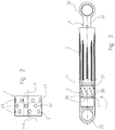
figure 1 is an exploded axonometric view of the friction damper according to the present invention; -
figure 2 is an enlarged side view of a friction element of the damper offigure 1 ; -
figure 3 is a side view partially in cross section of the damper offigure 1 assembled; -
figure 4A is an enlarged view in cross section of a detail of the damper offigure 3 in a first operating condition; -
figure 4B is an enlarged view in cross section of a detail of the damper offigure 3 in a second operating condition; -
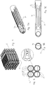
figure 5A is an axonometric view of the outer body of the damper of the invention; -
figure 5B is a plan view of the body offigure 5A ; -
figure 5C is a side view of the body offigure 5A ; -
figure 6 is a plan view of an assembly of four bodies offigure 5A ; -
figure 7 is an axonometric view of a stack of dampers of the invention. - With reference to
figure 1 , number 1 indicates generally a friction damper extending longitudinally along an X-X axis. The damper 1 comprises a hollowcylindrical body 2, arod 3 suitable to slidably engage the inside wall of saidhollow body 2, and at least one braking orfriction element 4 between the internal wall of the hollow cylindrical body and the external wall of the rod to provide the necessary frictional force. - The hollow
cylindrical body 2 includes a first closedend 21 on which is provided ananchoring element 22, such as a loop, suitable to fasten the damper 1 to a conventional cabinet or frame (not shown) of a laundry treatment machine. Asecond end 23 is open to engage therod 3. Preferably, the internal walls of the hollowcylindrical body 2 can be lined with a suitable layer of a material having a high resistance to wear, such as for example a metal foil or sleeve, such as a sheet of aluminium, which may be coated, or a film of thermoplastic polymeric material. - In accordance with a preferred embodiment of the invention, as shown in
figures 5A-5C , 6 a 7, thebody 2 can have two diametrically oppositeflat surfaces 24, and a plurality ofribs 25 protruding from the external surface of thebody 2 included between saidflat surfaces 24. In particular, theribs 25 can be arranged at least in part diametrically staggered so as to create a dap joint or in any case a stacking arrangement (see enlarged detail infigure 6 ). Advantageously, in fact, as shown infigure 7 , said arrangement makes it possible, using twosimple bands 26, to rapidly and safely fasten together a number of dampers in a compact manner. Further, the dap joint arrangement becomes self-supporting and makes it possible to operate directly in the assembly lines in an automatic manner, facilitating the management and handling of the individual pieces and eliminating packaging and relative waste disposal. - The rod 3 (
figure 1 ) includes a first closedend 31 on which is provided ananchoring element 32, for example a loop, for fastening to the tub of the machine, connected to asecond end 33 that engages the cavity of thecylindrical body 2 through amiddle portion 34. - In general, the
rod 3 has a substantially cylindrical shape having an outside diameter smaller than the inside diameter of the hollowcylindrical body 2. However, advantageously, therod 3 shown in the figures has somewhat the shape of a truncated cone, with a smaller diameter at the end provided with theloop 32, thus also allowing small lateral oscillations of the rod with respect to the hollow cylindrical body. In addition, themiddle portion 34 of therod 3 can be provided with a plurality ofopenings 35, variously distributed, suitable to dissipate the heat that is generated during the alternating movement of the rod inside the hollow cylindrical body. In particular, thefirst end 33 of therod 3 is provided with aseat 36 delimited by twoflanges 37 or shoulders suitable to receive thefriction element 4 coaxially to the rod. - Advantageously, the
flanges 37 are provided with pushing or abuttingelements 38 facing the direction of the axis X-X, that operate on thefriction element 4 and cause it to swell, as is better described hereunder. Saidelements 38 can be in the form of projections shaped so as to act as pushing elements without damaging the friction element. In particular, they are distributed along the surface of theflange 37 turned toward theseat 36 that holds said friction element. - As shown in
figures 2 and 3 , thefriction element 4 is preferably an annular band with a longitudinal axis Y-Y made, for example, of a polymeric material such as polyurethane foam, fitted onto saidseat 36 and held there by means of theflanges 37. Saidfriction element 4 has an externalannular contact surface 41 suitable to slidably cooperate with the inside surface of the hollowcylindrical body 2, and an internalannular contact surface 42 suitable to slidably cooperate with the external surface of therod 3 in theseat 36 on said rod (figure 1 ). - According to the invention, the
friction element 4 is provided with aplurality 43 of through holes on the wall of the element. During the operation, that is when therod 3 slides within thecylindrical body 2, as previously explained and as shown infigures 4A and 4B , the lubricant is drawn alternately toward one or theother shoulder 37 consequently to the oscillations transmitted by the movement of the drum in the laundry treatment machine. As a result, almost all the rubbing surface of thefriction element 4 remains without lubricant. This drawback is avoided with the solution of the present invention because theholes 43 function as a kind of containers or reservoirs holding the lubricant. In fact, the holes, once they are initially filled with lubricant, during the operation of the damper and as a result of the pressures applied on the friction element, release small quantities of lubricant in various areas of the friction element so that it can lubricate all the portions of the same. In this manner, the whole frictional surface is maintained suitably lubricated. - In addition, the
holes 43 work as a sort of pump that alternately releases and reabsorbs the lubricant. In other words, during the axial displacement of therod 3 outward from thehollow body 2, as infigure 4A , the part of theholes 43 positioned near theflange 37 closest to theloop 22 is subjected to compression by the pushingelements 38. This compression causes the expulsion of a certain quantity of lubricant. The moment when the axial displacement is reversed, that is toward the inside thebody 2, saidholes 43 expand and suck back part of the lubricant released with the previous compression. At the same time, as shown infigure 4B , theholes 43 near theflange 37 farthest from theloop 22 are subjected to compression by thecorresponding pushing elements 38. As in the previous case, there is a release of lubricant. When the movement is reversed, theholes 43 expand and suck in part of the lubricant previously released. - The above operation is then repeated cyclically with alternating compressions and expansions of the holes that work as a sort of reservoir releasing and reabsorbing the lubricant. The effect just described makes it possible to advantageously maintain a further automatic and optimal control of the correct lubrication of the parts involved in the braking or frictional action.
- It was found experimentally that the greater the penetration of the pushing
elements 38 into thefriction element 4, the greater is the elastic expansion of the same friction element, and thus the frictional intensity is also greater. This reaction is therefore not constant but varies in proportion of the unbalance to be dampened. In this manner, an automatic adjustment of the braking capacity of the damper is ensured. - In agreement with a preferred embodiment, the plurality of
holes 43 is distributed in one or more annular rows R1, R2, as shown infigure 2 . In particular, theholes 43 in one row are axially staggered with respect to theholes 43 in the next row. It was found that this distribution of the holes makes it possible to further improve the distribution of the lubricant. More preferably, the holes are staggered so that the tangential straight line in the axial direction of a hole in a row R1 coincides with the axially tangential straight line of the contiguous hole of the other row R2. In other words, the diameter of each hole must be equal to the distance between two contiguous holes. This last embodiment has proved to be best for an optimal distribution of lubricant, especially during an intense operation of the dampers. - Both the
rod 3 and the hollowcylindrical body 2 are conventionally made of a polymeric material of suitable firmness. - From the above, it is thus evident how a friction damper 1 according to the present invention resolves the previously mentioned drawbacks and achieves important advantages.
- In the first place, the even distribution of lubricant over all the surface of the friction element makes it possible to maintain advantageously optimum conditions of operation of the damper.
- The pumping effect previously described further increases the capability of correct distribution of the lubricant over the whole friction surface.
- Moreover, the efficiency of the damper is maintained unaltered, thanks to the correct distribution of the lubricant.
- Consequently, it is possible to avoid unwanted noise generated by improperly lubricated contact surfaces.
- At the same time, the excessive and early wear of the sliding parts is avoided, as well as the harmful overheating of the damper.
- The arrangement of the pushing elements also makes it possible to increase the efficiency of the damper, as the oscillations are minimized by simply causing a swelling or expansion of the friction element.
- Further, said friction damper 1 can be made simply and economically with the usual well-known systems, machines and equipment, while guaranteeing a reliable operation.
- The presence of the flat
external surfaces 24 and of therespective coupling ribs 25 makes it possible to rapidly stack the dampers or only the external bodies simply and rapidly so as to ready them properly for the assembly operations without requiring additional handling to prepare the package. - Variants or modifications of the damper described above are possible for a person skilled in the field without departing from the scope of patent protection of the present invention as defined in the enclosed claims.
- For example, shapes can be modified according to particular demands or preferences. In fact, the cross section of both the hollow body and of the rod can, for example, be square or rectangular, so that the friction element can be represented by a tampon applied on two opposite sides of the rod or fit by interference in a suitable slot to bulge from said opposite sides.
- The plastic materials with which the hollow body and the rod are made can be chosen from conventional plastics such as, for example, polyamide or polypropylene, possibly reinforced with mineral and/or natural or synthetic fibres. The friction element, on the other hand, can be made of natural or synthetic rubber, preferably foamed, such as foam polyurethane, ethyl vinyl acetate (EVA).
- Moreover, the materials forming the outside surface of the
seat 36 of therod 3 and the inside surface of the hollowcylindrical body 2 or its lining layer, or their surface roughness, can be different, so as to vary the friction coefficients of the two surfaces, and thus the principle that governs the movement relative to each other of the two bodies having the friction element 1 interposed therebetween. In this manner, it is possible to more accurately calibrate the degree of the damping effect. - The through holes 43 can be of any shape. In the figures, they are shown as having a circular shape, but they can also be oval, with the main axis disposed along to the X-X axis of the damper or transversal to it, or they may have a regular of irregular polygonal shape.
- Although the friction damper described herein is preferably used in a laundry washing machine, it is understood that it can be used for different applications, as may be required.
Claims (4)
- Friction damper (1) extending longitudinally along an axis (X-X), comprising a hollow body (2) having a first closed end (21) provided with a fixing element (22) and a second open end (23), a rod (3) for slidably engaging the inner wall of said hollow body (2), said rod having a first closed end (31) provided with a fixing element (32) and being connected to a second end (33) for engaging the cavity of the hollow body (2) through a middle portion (36), and at least a friction element (4) between the inner wall of the hollow body and the outer wall of the rod, said at least one friction element (4) being provided with a plurality of through holes (43) filled with a lubricant that is constantly released along the whole friction surface of said friction element during the functioning of the damper, wherein said plurality of holes (43) is disposed on one or more rows (R1, R2) orthogonally oriented with respect to the longitudinal axis (X-X) of the damper, the holes (43) of a row (R1) are axially staggered with respect to the holes (43) of the adjacent row (R2), characterized in that said hollow body (2) and said rod (3) have a generally cylindrical shape and said friction element (4) has a generally shape of an annular band, said friction element (4) is housed in a seat (36) delimited by two flanges (37) formed on the outer wall of said rod (3) on its second end (33), the flanges (37) have pushing or abutting elements (38) extending along the axis (X-X), which elements act on the friction element (4) causing its bulging, said elements (38) are teeth distributed along the annular surface of the flanges (37) towards the seat (36) housing said friction element (4) to compress the holes (43) in proximity of said teeth when the moving versus of the rod (3) is opposite with respect to the axial position of said holes with the effect of releasing some of the lubricant, while when the rod moves in the opposite direction the holes expand with the effect of recovering some lubricant.
- Friction damper (1) according to claim 1, wherein the diameter of each hole (43) is equal to the distance between two adjacent holes.
- Friction damper (1) according to any one of claims 1 or 2, wherein said middle portion (36) of the rod (3) is crossed by a plurality of apertures (37) for dissipating heat.
- Laundry treatment machine comprising at least one friction damper (7) according to any one of claims 1 to 3.
Priority Applications (1)
| Application Number | Priority Date | Filing Date | Title |
|---|---|---|---|
| PL13151875T PL2618018T3 (en) | 2012-01-23 | 2013-01-18 | Improved friction damper |
Applications Claiming Priority (1)
| Application Number | Priority Date | Filing Date | Title |
|---|---|---|---|
| IT000004A ITPN20120004A1 (en) | 2012-01-23 | 2012-01-23 | PERFECT BRAKING SHOCK ABSORBER |
Publications (3)
| Publication Number | Publication Date |
|---|---|
| EP2618018A1 EP2618018A1 (en) | 2013-07-24 |
| EP2618018B1 true EP2618018B1 (en) | 2020-08-26 |
| EP2618018B8 EP2618018B8 (en) | 2020-11-18 |
Family
ID=45955677
Family Applications (1)
| Application Number | Title | Priority Date | Filing Date |
|---|---|---|---|
| EP13151875.5A Active EP2618018B8 (en) | 2012-01-23 | 2013-01-18 | Improved friction damper |
Country Status (3)
| Country | Link |
|---|---|
| EP (1) | EP2618018B8 (en) |
| IT (1) | ITPN20120004A1 (en) |
| PL (1) | PL2618018T3 (en) |
Family Cites Families (5)
| Publication number | Priority date | Publication date | Assignee | Title |
|---|---|---|---|---|
| US2562595A (en) * | 1946-04-22 | 1951-07-31 | Chrysler Corp | Shock absorber |
| FR1435779A (en) * | 1964-06-13 | 1966-04-22 | Suspension complex for moving parts | |
| IT1268466B1 (en) * | 1993-12-16 | 1997-03-04 | R & D S Srl | DAMPER FOR WASHING MACHINES, IN PARTICULAR DOMESTIC WASHING MACHINES |
| US6202806B1 (en) * | 1997-10-29 | 2001-03-20 | Lord Corporation | Controllable device having a matrix medium retaining structure |
| WO2005033399A1 (en) * | 2003-10-06 | 2005-04-14 | Lg Electronics, Inc. | Damper in a washing machine and fabricating method of the same |
-
2012
- 2012-01-23 IT IT000004A patent/ITPN20120004A1/en unknown
-
2013
- 2013-01-18 PL PL13151875T patent/PL2618018T3/en unknown
- 2013-01-18 EP EP13151875.5A patent/EP2618018B8/en active Active
Non-Patent Citations (1)
| Title |
|---|
| None * |
Also Published As
| Publication number | Publication date |
|---|---|
| EP2618018A1 (en) | 2013-07-24 |
| PL2618018T3 (en) | 2021-04-19 |
| EP2618018B8 (en) | 2020-11-18 |
| ITPN20120004A1 (en) | 2013-07-24 |
Similar Documents
| Publication | Publication Date | Title |
|---|---|---|
| US6264014B1 (en) | Friction damper for washing machines or the like | |
| RU2599307C2 (en) | Radial vibration damper with free movement and domestic electrical appliance with damping system containing radial vibration damper | |
| US6202806B1 (en) | Controllable device having a matrix medium retaining structure | |
| KR20110131197A (en) | Decoupler featuring helical wrap clutch spring and coil damper spring | |
| KR101673725B1 (en) | Shock absorber having an improved friction element | |
| EP2377983A2 (en) | Laundry treating appliance suspension system | |
| EP2917396B1 (en) | Oscillation damper for a household appliance with rotating drum, and household appliance comprising the damper | |
| CN107663741A (en) | Hang shock mitigation system and washing machine | |
| EP2618018A1 (en) | Improved friction damper | |
| KR100856781B1 (en) | washer | |
| US2879873A (en) | Speed limiting torque metering vibration dampening clutch | |
| EP2618017A1 (en) | Friction damper with friction adjusting means | |
| CH649351A5 (en) | SLIDING BEARING WITH OSCILLATING HEELS. | |
| EP2336416B1 (en) | Household appliance with improved support stability | |
| WO2018086578A1 (en) | Shock absorption device for washing machine, and washing machine | |
| JP7008072B2 (en) | Torsion damping device | |
| RU2675472C1 (en) | Vibration cushioning device, electric household device and method for manufacturing this device | |
| KR101361415B1 (en) | Damper flywhell | |
| KR101285827B1 (en) | Damper | |
| KR101178579B1 (en) | Suspension damper having magnet for drum washing machine | |
| BRPI0904790A2 (en) | DAMPING DEVICE FOR THE SUSPENSION SYSTEM OF A CLOTHING WASHER | |
| US2604765A (en) | Overload release coupling | |
| JP2017086516A (en) | Washing machine | |
| EP2243873B1 (en) | Improved shock absorber particularly for washing and/or drying machines | |
| RU2469138C1 (en) | Washing machine of drum type |
Legal Events
| Date | Code | Title | Description |
|---|---|---|---|
| PUAI | Public reference made under article 153(3) epc to a published international application that has entered the european phase |
Free format text: ORIGINAL CODE: 0009012 |
|
| AK | Designated contracting states |
Kind code of ref document: A1 Designated state(s): AL AT BE BG CH CY CZ DE DK EE ES FI FR GB GR HR HU IE IS IT LI LT LU LV MC MK MT NL NO PL PT RO RS SE SI SK SM TR |
|
| AX | Request for extension of the european patent |
Extension state: BA ME |
|
| 17P | Request for examination filed |
Effective date: 20140120 |
|
| RBV | Designated contracting states (corrected) |
Designated state(s): AL AT BE BG CH CY CZ DE DK EE ES FI FR GB GR HR HU IE IS IT LI LT LU LV MC MK MT NL NO PL PT RO RS SE SI SK SM TR |
|
| STAA | Information on the status of an ep patent application or granted ep patent |
Free format text: STATUS: EXAMINATION IS IN PROGRESS |
|
| 17Q | First examination report despatched |
Effective date: 20190520 |
|
| GRAP | Despatch of communication of intention to grant a patent |
Free format text: ORIGINAL CODE: EPIDOSNIGR1 |
|
| STAA | Information on the status of an ep patent application or granted ep patent |
Free format text: STATUS: GRANT OF PATENT IS INTENDED |
|
| INTG | Intention to grant announced |
Effective date: 20200520 |
|
| GRAS | Grant fee paid |
Free format text: ORIGINAL CODE: EPIDOSNIGR3 |
|
| GRAA | (expected) grant |
Free format text: ORIGINAL CODE: 0009210 |
|
| STAA | Information on the status of an ep patent application or granted ep patent |
Free format text: STATUS: THE PATENT HAS BEEN GRANTED |
|
| AK | Designated contracting states |
Kind code of ref document: B1 Designated state(s): AL AT BE BG CH CY CZ DE DK EE ES FI FR GB GR HR HU IE IS IT LI LT LU LV MC MK MT NL NO PL PT RO RS SE SI SK SM TR |
|
| REG | Reference to a national code |
Ref country code: GB Ref legal event code: FG4D |
|
| REG | Reference to a national code |
Ref country code: CH Ref legal event code: EP |
|
| REG | Reference to a national code |
Ref country code: DE Ref legal event code: R096 Ref document number: 602013071906 Country of ref document: DE |
|
| REG | Reference to a national code |
Ref country code: AT Ref legal event code: REF Ref document number: 1306671 Country of ref document: AT Kind code of ref document: T Effective date: 20200915 |
|
| REG | Reference to a national code |
Ref country code: IE Ref legal event code: FG4D |
|
| REG | Reference to a national code |
Ref country code: DE Ref legal event code: R081 Ref document number: 602013071906 Country of ref document: DE Owner name: ROSA PLAST S.R.L., PORCIA, IT Free format text: FORMER OWNER: RO-SA PLAST S.P.A., PORCIA, PORDENONE, IT |
|
| RAP2 | Party data changed (patent owner data changed or rights of a patent transferred) |
Owner name: ROSA PLAST S.R.L. |
|
| REG | Reference to a national code |
Ref country code: CH Ref legal event code: PK Free format text: BERICHTIGUNG B8 |
|
| REG | Reference to a national code |
Ref country code: LT Ref legal event code: MG4D |
|
| PG25 | Lapsed in a contracting state [announced via postgrant information from national office to epo] |
Ref country code: SE Free format text: LAPSE BECAUSE OF FAILURE TO SUBMIT A TRANSLATION OF THE DESCRIPTION OR TO PAY THE FEE WITHIN THE PRESCRIBED TIME-LIMIT Effective date: 20200826 Ref country code: PT Free format text: LAPSE BECAUSE OF FAILURE TO SUBMIT A TRANSLATION OF THE DESCRIPTION OR TO PAY THE FEE WITHIN THE PRESCRIBED TIME-LIMIT Effective date: 20201228 Ref country code: FI Free format text: LAPSE BECAUSE OF FAILURE TO SUBMIT A TRANSLATION OF THE DESCRIPTION OR TO PAY THE FEE WITHIN THE PRESCRIBED TIME-LIMIT Effective date: 20200826 Ref country code: GR Free format text: LAPSE BECAUSE OF FAILURE TO SUBMIT A TRANSLATION OF THE DESCRIPTION OR TO PAY THE FEE WITHIN THE PRESCRIBED TIME-LIMIT Effective date: 20201127 Ref country code: LT Free format text: LAPSE BECAUSE OF FAILURE TO SUBMIT A TRANSLATION OF THE DESCRIPTION OR TO PAY THE FEE WITHIN THE PRESCRIBED TIME-LIMIT Effective date: 20200826 Ref country code: HR Free format text: LAPSE BECAUSE OF FAILURE TO SUBMIT A TRANSLATION OF THE DESCRIPTION OR TO PAY THE FEE WITHIN THE PRESCRIBED TIME-LIMIT Effective date: 20200826 Ref country code: BG Free format text: LAPSE BECAUSE OF FAILURE TO SUBMIT A TRANSLATION OF THE DESCRIPTION OR TO PAY THE FEE WITHIN THE PRESCRIBED TIME-LIMIT Effective date: 20201126 Ref country code: NO Free format text: LAPSE BECAUSE OF FAILURE TO SUBMIT A TRANSLATION OF THE DESCRIPTION OR TO PAY THE FEE WITHIN THE PRESCRIBED TIME-LIMIT Effective date: 20201126 |
|
| REG | Reference to a national code |
Ref country code: NL Ref legal event code: MP Effective date: 20200826 |
|
| REG | Reference to a national code |
Ref country code: AT Ref legal event code: MK05 Ref document number: 1306671 Country of ref document: AT Kind code of ref document: T Effective date: 20200826 |
|
| PG25 | Lapsed in a contracting state [announced via postgrant information from national office to epo] |
Ref country code: IS Free format text: LAPSE BECAUSE OF FAILURE TO SUBMIT A TRANSLATION OF THE DESCRIPTION OR TO PAY THE FEE WITHIN THE PRESCRIBED TIME-LIMIT Effective date: 20201226 Ref country code: RS Free format text: LAPSE BECAUSE OF FAILURE TO SUBMIT A TRANSLATION OF THE DESCRIPTION OR TO PAY THE FEE WITHIN THE PRESCRIBED TIME-LIMIT Effective date: 20200826 Ref country code: LV Free format text: LAPSE BECAUSE OF FAILURE TO SUBMIT A TRANSLATION OF THE DESCRIPTION OR TO PAY THE FEE WITHIN THE PRESCRIBED TIME-LIMIT Effective date: 20200826 Ref country code: NL Free format text: LAPSE BECAUSE OF FAILURE TO SUBMIT A TRANSLATION OF THE DESCRIPTION OR TO PAY THE FEE WITHIN THE PRESCRIBED TIME-LIMIT Effective date: 20200826 |
|
| PG25 | Lapsed in a contracting state [announced via postgrant information from national office to epo] |
Ref country code: RO Free format text: LAPSE BECAUSE OF FAILURE TO SUBMIT A TRANSLATION OF THE DESCRIPTION OR TO PAY THE FEE WITHIN THE PRESCRIBED TIME-LIMIT Effective date: 20200826 Ref country code: SM Free format text: LAPSE BECAUSE OF FAILURE TO SUBMIT A TRANSLATION OF THE DESCRIPTION OR TO PAY THE FEE WITHIN THE PRESCRIBED TIME-LIMIT Effective date: 20200826 Ref country code: EE Free format text: LAPSE BECAUSE OF FAILURE TO SUBMIT A TRANSLATION OF THE DESCRIPTION OR TO PAY THE FEE WITHIN THE PRESCRIBED TIME-LIMIT Effective date: 20200826 Ref country code: DK Free format text: LAPSE BECAUSE OF FAILURE TO SUBMIT A TRANSLATION OF THE DESCRIPTION OR TO PAY THE FEE WITHIN THE PRESCRIBED TIME-LIMIT Effective date: 20200826 Ref country code: CZ Free format text: LAPSE BECAUSE OF FAILURE TO SUBMIT A TRANSLATION OF THE DESCRIPTION OR TO PAY THE FEE WITHIN THE PRESCRIBED TIME-LIMIT Effective date: 20200826 |
|
| REG | Reference to a national code |
Ref country code: DE Ref legal event code: R097 Ref document number: 602013071906 Country of ref document: DE |
|
| PG25 | Lapsed in a contracting state [announced via postgrant information from national office to epo] |
Ref country code: ES Free format text: LAPSE BECAUSE OF FAILURE TO SUBMIT A TRANSLATION OF THE DESCRIPTION OR TO PAY THE FEE WITHIN THE PRESCRIBED TIME-LIMIT Effective date: 20200826 Ref country code: AL Free format text: LAPSE BECAUSE OF FAILURE TO SUBMIT A TRANSLATION OF THE DESCRIPTION OR TO PAY THE FEE WITHIN THE PRESCRIBED TIME-LIMIT Effective date: 20200826 Ref country code: AT Free format text: LAPSE BECAUSE OF FAILURE TO SUBMIT A TRANSLATION OF THE DESCRIPTION OR TO PAY THE FEE WITHIN THE PRESCRIBED TIME-LIMIT Effective date: 20200826 |
|
| PG25 | Lapsed in a contracting state [announced via postgrant information from national office to epo] |
Ref country code: SK Free format text: LAPSE BECAUSE OF FAILURE TO SUBMIT A TRANSLATION OF THE DESCRIPTION OR TO PAY THE FEE WITHIN THE PRESCRIBED TIME-LIMIT Effective date: 20200826 |
|
| PLBE | No opposition filed within time limit |
Free format text: ORIGINAL CODE: 0009261 |
|
| STAA | Information on the status of an ep patent application or granted ep patent |
Free format text: STATUS: NO OPPOSITION FILED WITHIN TIME LIMIT |
|
| 26N | No opposition filed |
Effective date: 20210527 |
|
| PG25 | Lapsed in a contracting state [announced via postgrant information from national office to epo] |
Ref country code: SI Free format text: LAPSE BECAUSE OF FAILURE TO SUBMIT A TRANSLATION OF THE DESCRIPTION OR TO PAY THE FEE WITHIN THE PRESCRIBED TIME-LIMIT Effective date: 20200826 Ref country code: MC Free format text: LAPSE BECAUSE OF FAILURE TO SUBMIT A TRANSLATION OF THE DESCRIPTION OR TO PAY THE FEE WITHIN THE PRESCRIBED TIME-LIMIT Effective date: 20200826 |
|
| REG | Reference to a national code |
Ref country code: CH Ref legal event code: PL |
|
| GBPC | Gb: european patent ceased through non-payment of renewal fee |
Effective date: 20210118 |
|
| PG25 | Lapsed in a contracting state [announced via postgrant information from national office to epo] |
Ref country code: LU Free format text: LAPSE BECAUSE OF NON-PAYMENT OF DUE FEES Effective date: 20210118 |
|
| REG | Reference to a national code |
Ref country code: BE Ref legal event code: MM Effective date: 20210131 |
|
| PG25 | Lapsed in a contracting state [announced via postgrant information from national office to epo] |
Ref country code: FR Free format text: LAPSE BECAUSE OF NON-PAYMENT OF DUE FEES Effective date: 20210131 |
|
| PG25 | Lapsed in a contracting state [announced via postgrant information from national office to epo] |
Ref country code: LI Free format text: LAPSE BECAUSE OF NON-PAYMENT OF DUE FEES Effective date: 20210131 Ref country code: CH Free format text: LAPSE BECAUSE OF NON-PAYMENT OF DUE FEES Effective date: 20210131 Ref country code: GB Free format text: LAPSE BECAUSE OF NON-PAYMENT OF DUE FEES Effective date: 20210118 |
|
| PG25 | Lapsed in a contracting state [announced via postgrant information from national office to epo] |
Ref country code: IE Free format text: LAPSE BECAUSE OF NON-PAYMENT OF DUE FEES Effective date: 20210118 |
|
| PG25 | Lapsed in a contracting state [announced via postgrant information from national office to epo] |
Ref country code: IS Free format text: LAPSE BECAUSE OF FAILURE TO SUBMIT A TRANSLATION OF THE DESCRIPTION OR TO PAY THE FEE WITHIN THE PRESCRIBED TIME-LIMIT Effective date: 20201226 |
|
| PG25 | Lapsed in a contracting state [announced via postgrant information from national office to epo] |
Ref country code: BE Free format text: LAPSE BECAUSE OF NON-PAYMENT OF DUE FEES Effective date: 20210131 |
|
| PG25 | Lapsed in a contracting state [announced via postgrant information from national office to epo] |
Ref country code: HU Free format text: LAPSE BECAUSE OF FAILURE TO SUBMIT A TRANSLATION OF THE DESCRIPTION OR TO PAY THE FEE WITHIN THE PRESCRIBED TIME-LIMIT; INVALID AB INITIO Effective date: 20130118 |
|
| P01 | Opt-out of the competence of the unified patent court (upc) registered |
Effective date: 20230508 |
|
| PG25 | Lapsed in a contracting state [announced via postgrant information from national office to epo] |
Ref country code: CY Free format text: LAPSE BECAUSE OF FAILURE TO SUBMIT A TRANSLATION OF THE DESCRIPTION OR TO PAY THE FEE WITHIN THE PRESCRIBED TIME-LIMIT Effective date: 20200826 |
|
| PG25 | Lapsed in a contracting state [announced via postgrant information from national office to epo] |
Ref country code: MK Free format text: LAPSE BECAUSE OF FAILURE TO SUBMIT A TRANSLATION OF THE DESCRIPTION OR TO PAY THE FEE WITHIN THE PRESCRIBED TIME-LIMIT Effective date: 20200826 |
|
| PG25 | Lapsed in a contracting state [announced via postgrant information from national office to epo] |
Ref country code: MT Free format text: LAPSE BECAUSE OF FAILURE TO SUBMIT A TRANSLATION OF THE DESCRIPTION OR TO PAY THE FEE WITHIN THE PRESCRIBED TIME-LIMIT Effective date: 20200826 |
|
| PGFP | Annual fee paid to national office [announced via postgrant information from national office to epo] |
Ref country code: PL Payment date: 20251222 Year of fee payment: 14 |
|
| PGFP | Annual fee paid to national office [announced via postgrant information from national office to epo] |
Ref country code: DE Payment date: 20260121 Year of fee payment: 14 |
|
| PGFP | Annual fee paid to national office [announced via postgrant information from national office to epo] |
Ref country code: IT Payment date: 20260109 Year of fee payment: 14 |
|
| PGFP | Annual fee paid to national office [announced via postgrant information from national office to epo] |
Ref country code: TR Payment date: 20260115 Year of fee payment: 14 |