EP2618012A1 - Wheel hub rolling bearing unit for a motor vehicle with a cold forged inner ring and a seal - Google Patents
Wheel hub rolling bearing unit for a motor vehicle with a cold forged inner ring and a seal Download PDFInfo
- Publication number
- EP2618012A1 EP2618012A1 EP13151403.6A EP13151403A EP2618012A1 EP 2618012 A1 EP2618012 A1 EP 2618012A1 EP 13151403 A EP13151403 A EP 13151403A EP 2618012 A1 EP2618012 A1 EP 2618012A1
- Authority
- EP
- European Patent Office
- Prior art keywords
- ring member
- inner ring
- lateral direction
- vehicle lateral
- end portion
- Prior art date
- Legal status (The legal status is an assumption and is not a legal conclusion. Google has not performed a legal analysis and makes no representation as to the accuracy of the status listed.)
- Withdrawn
Links
Images


Classifications
-
- B—PERFORMING OPERATIONS; TRANSPORTING
- B60—VEHICLES IN GENERAL
- B60B—VEHICLE WHEELS; CASTORS; AXLES FOR WHEELS OR CASTORS; INCREASING WHEEL ADHESION
- B60B27/00—Hubs
- B60B27/0005—Hubs with ball bearings
-
- B—PERFORMING OPERATIONS; TRANSPORTING
- B21—MECHANICAL METAL-WORKING WITHOUT ESSENTIALLY REMOVING MATERIAL; PUNCHING METAL
- B21K—MAKING FORGED OR PRESSED METAL PRODUCTS, e.g. HORSE-SHOES, RIVETS, BOLTS OR WHEELS
- B21K1/00—Making machine elements
- B21K1/28—Making machine elements wheels; discs
- B21K1/40—Making machine elements wheels; discs hubs
-
- B—PERFORMING OPERATIONS; TRANSPORTING
- B60—VEHICLES IN GENERAL
- B60B—VEHICLE WHEELS; CASTORS; AXLES FOR WHEELS OR CASTORS; INCREASING WHEEL ADHESION
- B60B27/00—Hubs
- B60B27/0073—Hubs characterised by sealing means
-
- F—MECHANICAL ENGINEERING; LIGHTING; HEATING; WEAPONS; BLASTING
- F16—ENGINEERING ELEMENTS AND UNITS; GENERAL MEASURES FOR PRODUCING AND MAINTAINING EFFECTIVE FUNCTIONING OF MACHINES OR INSTALLATIONS; THERMAL INSULATION IN GENERAL
- F16C—SHAFTS; FLEXIBLE SHAFTS; ELEMENTS OR CRANKSHAFT MECHANISMS; ROTARY BODIES OTHER THAN GEARING ELEMENTS; BEARINGS
- F16C19/00—Bearings with rolling contact, for exclusively rotary movement
- F16C19/02—Bearings with rolling contact, for exclusively rotary movement with bearing balls essentially of the same size in one or more circular rows
- F16C19/14—Bearings with rolling contact, for exclusively rotary movement with bearing balls essentially of the same size in one or more circular rows for both radial and axial load
- F16C19/18—Bearings with rolling contact, for exclusively rotary movement with bearing balls essentially of the same size in one or more circular rows for both radial and axial load with two or more rows of balls
- F16C19/181—Bearings with rolling contact, for exclusively rotary movement with bearing balls essentially of the same size in one or more circular rows for both radial and axial load with two or more rows of balls with angular contact
- F16C19/183—Bearings with rolling contact, for exclusively rotary movement with bearing balls essentially of the same size in one or more circular rows for both radial and axial load with two or more rows of balls with angular contact with two rows at opposite angles
- F16C19/184—Bearings with rolling contact, for exclusively rotary movement with bearing balls essentially of the same size in one or more circular rows for both radial and axial load with two or more rows of balls with angular contact with two rows at opposite angles in O-arrangement
- F16C19/186—Bearings with rolling contact, for exclusively rotary movement with bearing balls essentially of the same size in one or more circular rows for both radial and axial load with two or more rows of balls with angular contact with two rows at opposite angles in O-arrangement with three raceways provided integrally on parts other than race rings, e.g. third generation hubs
-
- F—MECHANICAL ENGINEERING; LIGHTING; HEATING; WEAPONS; BLASTING
- F16—ENGINEERING ELEMENTS AND UNITS; GENERAL MEASURES FOR PRODUCING AND MAINTAINING EFFECTIVE FUNCTIONING OF MACHINES OR INSTALLATIONS; THERMAL INSULATION IN GENERAL
- F16C—SHAFTS; FLEXIBLE SHAFTS; ELEMENTS OR CRANKSHAFT MECHANISMS; ROTARY BODIES OTHER THAN GEARING ELEMENTS; BEARINGS
- F16C33/00—Parts of bearings; Special methods for making bearings or parts thereof
- F16C33/30—Parts of ball or roller bearings
- F16C33/58—Raceways; Race rings
- F16C33/583—Details of specific parts of races
- F16C33/586—Details of specific parts of races outside the space between the races, e.g. end faces or bore of inner ring
-
- F—MECHANICAL ENGINEERING; LIGHTING; HEATING; WEAPONS; BLASTING
- F16—ENGINEERING ELEMENTS AND UNITS; GENERAL MEASURES FOR PRODUCING AND MAINTAINING EFFECTIVE FUNCTIONING OF MACHINES OR INSTALLATIONS; THERMAL INSULATION IN GENERAL
- F16C—SHAFTS; FLEXIBLE SHAFTS; ELEMENTS OR CRANKSHAFT MECHANISMS; ROTARY BODIES OTHER THAN GEARING ELEMENTS; BEARINGS
- F16C33/00—Parts of bearings; Special methods for making bearings or parts thereof
- F16C33/30—Parts of ball or roller bearings
- F16C33/58—Raceways; Race rings
- F16C33/64—Special methods of manufacture
-
- F—MECHANICAL ENGINEERING; LIGHTING; HEATING; WEAPONS; BLASTING
- F16—ENGINEERING ELEMENTS AND UNITS; GENERAL MEASURES FOR PRODUCING AND MAINTAINING EFFECTIVE FUNCTIONING OF MACHINES OR INSTALLATIONS; THERMAL INSULATION IN GENERAL
- F16C—SHAFTS; FLEXIBLE SHAFTS; ELEMENTS OR CRANKSHAFT MECHANISMS; ROTARY BODIES OTHER THAN GEARING ELEMENTS; BEARINGS
- F16C33/00—Parts of bearings; Special methods for making bearings or parts thereof
- F16C33/72—Sealings
- F16C33/76—Sealings of ball or roller bearings
- F16C33/78—Sealings of ball or roller bearings with a diaphragm, disc, or ring, with or without resilient members
- F16C33/7816—Details of the sealing or parts thereof, e.g. geometry, material
- F16C33/782—Details of the sealing or parts thereof, e.g. geometry, material of the sealing region
- F16C33/7826—Details of the sealing or parts thereof, e.g. geometry, material of the sealing region of the opposing surface cooperating with the seal, e.g. a shoulder surface of a bearing ring
-
- F—MECHANICAL ENGINEERING; LIGHTING; HEATING; WEAPONS; BLASTING
- F16—ENGINEERING ELEMENTS AND UNITS; GENERAL MEASURES FOR PRODUCING AND MAINTAINING EFFECTIVE FUNCTIONING OF MACHINES OR INSTALLATIONS; THERMAL INSULATION IN GENERAL
- F16C—SHAFTS; FLEXIBLE SHAFTS; ELEMENTS OR CRANKSHAFT MECHANISMS; ROTARY BODIES OTHER THAN GEARING ELEMENTS; BEARINGS
- F16C33/00—Parts of bearings; Special methods for making bearings or parts thereof
- F16C33/72—Sealings
- F16C33/76—Sealings of ball or roller bearings
- F16C33/78—Sealings of ball or roller bearings with a diaphragm, disc, or ring, with or without resilient members
- F16C33/7886—Sealings of ball or roller bearings with a diaphragm, disc, or ring, with or without resilient members mounted outside the gap between the inner and outer races, e.g. sealing rings mounted to an end face or outer surface of a race
-
- B—PERFORMING OPERATIONS; TRANSPORTING
- B60—VEHICLES IN GENERAL
- B60B—VEHICLE WHEELS; CASTORS; AXLES FOR WHEELS OR CASTORS; INCREASING WHEEL ADHESION
- B60B27/00—Hubs
-
- F—MECHANICAL ENGINEERING; LIGHTING; HEATING; WEAPONS; BLASTING
- F16—ENGINEERING ELEMENTS AND UNITS; GENERAL MEASURES FOR PRODUCING AND MAINTAINING EFFECTIVE FUNCTIONING OF MACHINES OR INSTALLATIONS; THERMAL INSULATION IN GENERAL
- F16C—SHAFTS; FLEXIBLE SHAFTS; ELEMENTS OR CRANKSHAFT MECHANISMS; ROTARY BODIES OTHER THAN GEARING ELEMENTS; BEARINGS
- F16C2220/00—Shaping
- F16C2220/40—Shaping by deformation without removing material
- F16C2220/46—Shaping by deformation without removing material by forging
-
- F—MECHANICAL ENGINEERING; LIGHTING; HEATING; WEAPONS; BLASTING
- F16—ENGINEERING ELEMENTS AND UNITS; GENERAL MEASURES FOR PRODUCING AND MAINTAINING EFFECTIVE FUNCTIONING OF MACHINES OR INSTALLATIONS; THERMAL INSULATION IN GENERAL
- F16C—SHAFTS; FLEXIBLE SHAFTS; ELEMENTS OR CRANKSHAFT MECHANISMS; ROTARY BODIES OTHER THAN GEARING ELEMENTS; BEARINGS
- F16C2240/00—Specified values or numerical ranges of parameters; Relations between them
- F16C2240/40—Linear dimensions, e.g. length, radius, thickness, gap
- F16C2240/60—Thickness, e.g. thickness of coatings
-
- F—MECHANICAL ENGINEERING; LIGHTING; HEATING; WEAPONS; BLASTING
- F16—ENGINEERING ELEMENTS AND UNITS; GENERAL MEASURES FOR PRODUCING AND MAINTAINING EFFECTIVE FUNCTIONING OF MACHINES OR INSTALLATIONS; THERMAL INSULATION IN GENERAL
- F16C—SHAFTS; FLEXIBLE SHAFTS; ELEMENTS OR CRANKSHAFT MECHANISMS; ROTARY BODIES OTHER THAN GEARING ELEMENTS; BEARINGS
- F16C2326/00—Articles relating to transporting
- F16C2326/01—Parts of vehicles in general
- F16C2326/02—Wheel hubs or castors
Definitions
- the shaft portion 11 of the inner ring member 10 is formed as a stepped shaft in which a portion on the flange portion 18 side is larger in diameter than a portion on the distal end side.
- an inner ring raceway surface 32 that is on the outer side in the vehicle lateral direction is formed on the outer periphery of a large-diameter portion 12 of the shaft portion 11.
- An inner ring member 31 is fitted to the outer periphery of a small-diameter portion 13 of the shaft portion 11.
- the inner ring member 31 has, on its outer periphery, an inner ring raceway surface 33 that is on the inner side of the inner ring raceway surface 32 in the vehicle lateral direction.
- a tapered surface 135 is formed in the inner ring member 110 as in the first embodiment so as to gradually increase in diameter from the inner side toward the outer side in the vehicle lateral direction over a region from a position near root portions of inner side faces of flange portions 118 (inner side faces of the flange portions 118 in the vehicle lateral direction) to a position close to bolt seat faces 122 of the flange portions 118.
- the root portions of the inner side faces of the flange portions 118 are located adjacent to a raceway shoulder portion 134 of an inner ring raceway surface 132 on the outer side in the vehicle lateral direction.
- a seal member that uses the tapered surface 135 of the inner ring member 110 as a sealing face as in the first embodiment is attached to the outer periphery of an outer end portion of an outer ring member (not shown) in the vehicle lateral direction.
Landscapes
- Engineering & Computer Science (AREA)
- General Engineering & Computer Science (AREA)
- Mechanical Engineering (AREA)
- Manufacturing & Machinery (AREA)
- Rolling Contact Bearings (AREA)
- Forging (AREA)
Abstract
Description
- The invention relates to a wheel rolling bearing device.
- There is a wheel rolling bearing device that is configured to include an inner ring member, an outer ring member and a plurality of rolling elements. The inner ring member has a shaft portion, and a plurality of flange portions is formed on the outer periphery of the shaft portion so as to radiate from the shaft portion. A wheel is fastened to the flange portions. The outer ring member is arranged radially outward of the outer periphery of the shaft portion of the inner ring member via an annular space. The rolling elements are rollably arranged in the annular space between the inner ring member and the outer ring member. There is a wheel rolling bearing device in which a plurality of flange portions is formed, by cold lateral extrusion, on the outer periphery of a shaft portion of an inner ring member so as to radiate from the shaft portion (for example, see Japanese Patent Application Publication No.
2006-111070 JP 2006-111070 A - In the above-described wheel rolling bearing device, a distal end portion of the seal lip of the seal member is in sliding contact with the turned face of the outer periphery of the raceway shoulder portion of the inner ring member. Therefore, if the distal end portion of the seal lip abrades, poor sealing may occur.
- It is an object of the invention to provide a wheel rolling bearing device in which sufficient sealing performance is maintained for a long period of time.
- An aspect of the invention relates to a wheel rolling bearing device, including: an inner ring member where multiple flange portions, to which a wheel is fastened, are formed on an outer periphery of a shaft portion so as to radiate from the shaft portion; an outer ring member that is arranged radially outward of the outer periphery of the shaft portion of the inner ring member via an annular space; and a plurality of rolling elements that are rollably arranged in the annular space between the inner ring member and the outer ring member. The inner ring member is formed by cold forging. A tapered surface is formed in a state of a forged surface on the inner ring member so as to gradually increase in diameter from an inner side toward an outer side in a vehicle lateral direction over a region from a position near root portions of inner side faces of the flange portions in the vehicle lateral direction to a position radially outward of an outer periphery of an outer end portion of the outer ring member in the vehicle lateral direction. A seal member is attached to the outer periphery of the outer end portion of the outer ring member. A seal lip that is in sliding contact with the tapered surface in the state of a forged surface is formed at a distal end portion of the seal member.
- The foregoing and further features and advantages of the invention will become apparent from the following description of example embodiments with reference to the accompanying drawings, wherein like numerals are used to represent like elements and wherein:
-
FIG. 1 is an axial sectional view that shows a wheel rolling bearing device according to a first embodiment of the invention; -
FIG. 2 is a view that shows an inner ring member according to the first embodiment as viewed from a forged recess side along an arrow II inFIG. 1 ; -
FIG. 3 is an enlarged axial sectional view that shows a shaft portion, a fitting shaft portion and a flange portion of the inner ring member according to the first embodiment; -
FIG. 4 is an enlarged axial sectional view that shows a shaft portion, a fitting shaft portion and a flange portion of an inner ring member of a wheel rolling bearing device according to a second embodiment of the invention; and -
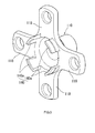
FIG. 5 is a perspective view that shows the inner ring member according to the second embodiment as viewed from the fitting shaft portion side. - Hereinafter, example embodiments of the invention will be described with reference to the accompanying drawings.
- A wheel rolling bearing device according to a first embodiment of the invention will be described with reference to
FIG. 1 to FIG. 3 . As shown inFIG. 1 , the wheel rolling bearing device (wheel hub unit) is an assembly unit that includes aninner ring member 10, anouter ring member 51 androlling elements inner ring member 10 is formed by cold forging. Theinner ring member 10 is a single-piece member that has ashaft portion 11, afitting shaft portion 40, aflange base portion 23 and a plurality offlange portions 18. Theflange portions 18 radiate from the outer periphery of theflange base portion 23 outward in the radial direction. Thefitting shaft portion 40 is formed at one end of theshaft portion 11, and has a diameter larger than that of theshaft portion 11. Thefitting shaft portion 40 is fitted in a center hole of a wheel (not shown). Theflange base portion 23 is located between theshaft portion 11 and thefitting shaft portion 40. -
Bolt holes 21 are formed so as to pass through therespective flange portions 18.Hub bolts 25 that are used to fasten the wheel are press-fitted in therespective bolt holes 21. Thefitting shaft portion 40 has a brakerotor fitting portion 41 located adjacent to theflange portions 18. The brakerotor fitting portion 41 is fitted in a center hole of abrake rotor 55. Awheel fitting portion 42 is formed at a distal end portion of thefitting shaft portion 40. Thewheel fitting portion 42 has a diameter slightly smaller than that of the brakerotor fitting portion 41. Thewheel fitting portion 42 is fitted in the center hole of the wheel. Aforged recess 46 is formed by cold forging at a center portion of an outer end face of thefitting shaft portion 40 in the vehicle lateral direction. - In the first embodiment, the
shaft portion 11 of theinner ring member 10 is formed as a stepped shaft in which a portion on theflange portion 18 side is larger in diameter than a portion on the distal end side. Further, an innerring raceway surface 32 that is on the outer side in the vehicle lateral direction is formed on the outer periphery of a large-diameter portion 12 of theshaft portion 11. Aninner ring member 31 is fitted to the outer periphery of a small-diameter portion 13 of theshaft portion 11. Theinner ring member 31 has, on its outer periphery, an innerring raceway surface 33 that is on the inner side of the innerring raceway surface 32 in the vehicle lateral direction. Furthermore, ashaft end portion 15 having the same diameter as the small-diameter portion 13 is formed at a distal end portion of theshaft portion 11. A distal end portion of theshaft end portion 15 is clinched radially outward to form a clinched portion 17. In this way, theinner ring member 31 is fixed to the outer periphery of the small-diameter portion 13. - A
tapered surface 35 is formed in the state of a forged surface so as to gradually increase in diameter from the inner side toward the outer side in the vehicle lateral direction over a region from a position near root portions of inner side faces of the flange portions 18 (inner side faces of theflange portions 18 in the vehicle lateral direction) to a position radially outward of the outer periphery of an outer end portion of the outer ring member 51 (outer end portion of theouter ring member 51 in the vehicle lateral direction) (described later). The root portions of the inner side faces of theflange portions 18 are located adjacent to araceway shoulder portion 34 of the innerring raceway surface 32 formed on theshaft portion 11 of theinner ring member 10. In the first embodiment, thetapered surface 35 is formed so as to gradually increase in diameter from the inner side toward the outer side in the vehicle lateral direction over a region from a position near the root portions of the inner side faces of theflange portions 18, which are located adjacent to theraceway shoulder portion 34, to a position close to bolt seat faces 22 of theflange portions 18. - In the first embodiment, as shown in
FIG. 3 , the outer periphery of theraceway shoulder portion 34, thetapered surface 35, and the entirety of the inner side faces of theflange portions 18 are covered with alubricant coat 37. The lubricant coat (phosphate coat) 37 is formed as follows. In a coating process that is a preceding process before cold forging of theinner ring member 10, phosphate is applied onto the surface of a material that will be theinner ring member 10. Even after cold forging of theinner ring member 10, the outer periphery of theraceway shoulder portion 34, thetapered surface 35, and the entirety of the inner side faces of theflange portions 18 are in the state of a forged surface on which thelubricant coat 37 is left and which is not subjected to turning. After cold forging of theinner ring member 10, the innerring raceway surface 32, part of theraceway shoulder portion 34, the outer periphery of the large-diameter portion 12, a step surface between the large-diameter portion 12 and the small-diameter portion 13 and the outer periphery of the small-diameter portion 13, which are indicated by hatching inFIG. 1 , are subjected to turning, and then subjected to heat treatment (quenching). After that, the surface of the heat treated portion is subjected to grinding. - The
outer ring member 51 is formed in a cylindrical shape, and is arranged radially outward of the outer periphery of theshaft portion 11 of theinner ring member 10 via an annular space, on the same central axis of theinner ring member 10. An outerring raceway surface 52 and an outerring raceway surface 53, which is on the inner side of the outerring raceway surface 52 in the vehicle lateral direction, are formed on the inner periphery of theouter ring member 51 at axial positions that correspond to the innerring raceway surface 32 and the innerring raceway surface 33, respectively. The rollingelements 56 are rollably arranged between the innerring raceway surface 32 and the outerring raceway surface 52 with the rollingelements 56 retained by acage 58. The rollingelements 57 are rollably arranged between the innerring raceway surface 33 and the innerring raceway surface 53 with the rollingelements 57 retained by acage 59. Thus, a double row rolling bearing (angular contact ball bearing inFIG. 1 ) is formed. - A required axial preload based on a clinching force at the time of forming the clinched portion 17 by clinching the
shaft end portion 15 of theshaft portion 11 is applied to the rolling elements (balls) 56 that are arranged between the innerring raceway surface 32 and the outerring raceway surface 52 and the rolling elements (balls) 57 that are arranged between the innerring raceway surface 33 and the outerring raceway surface 53. A fixingflange 54 is integrally formed with the outer periphery of theouter ring member 51. The fixingflange 54 is fastened to a fitting face of a vehicle body-side member, such as a knuckle and a carrier, with bolts. The vehicle body-side member is supported by a suspension (not shown) of a vehicle. - As shown in
FIG. 3 , aseal member 60 is attached to the outer periphery of the outer end portion of theouter ring member 51. A body portion of theseal member 60 is formed of acore metal 61. Thecore metal 61 has acylindrical portion 62, a radially outer side extendedportion 63 and a radially inner sideannular portion 65. Thecylindrical portion 62 is folded into inner and outer two layers and formed in a cylindrical shape, and is fixedly press-fitted to the outer periphery of the outer end portion of theouter ring member 51. The radially outer side extendedportion 63 extends from an outer end portion of a radiallyouter side portion 62a (outer end portion of the radiallyouter side portion 62a in the vehicle lateral direction) of thecylindrical portion 62 toward the taperedsurface 35. The radially inner sideannular portion 65 is formed through bending so to extend radially inward from an outer end portion of a radiallyinner side portion 62b (outer end portion of the radiallyinner side portion 62b in the vehicle lateral direction) of thecylindrical portion 62. A base portion of a seal lip (axial lip) 64 is fixedly attached to a distal end portion of the radially outer side extendedportion 63 by cure adhesion. Theseal lip 64 has rubber elasticity and is in sliding contact with the taperedsurface 35. A base portion of a seal lip (radial lip) 66 is fixedly attached to a radially inner end portion of the radially inner sideannular portion 65 with a slight clearance left between theseal lip 66 and the outer periphery of theraceway shoulder portion 34 by cure adhesion. Theseal lip 66 has rubber elasticity and forms a labyrinth in cooperation with the outer periphery of theraceway shoulder portion 34. - The wheel rolling bearing device according to the first embodiment is configured as described above. Therefore, the tapered
surface 35 is formed in the state of a forged surface (forged surface on which thelubricant coat 37 is left) over a region from a position near the root portions of the inner side faces of theflange portions 18 of theinner ring member 10, which are formed by cold forging, to a position radially outward of the outer periphery of the outer end portion of theouter ring member 51, and, in the first embodiment, a region from the outer end portion of theraceway shoulder portion 34 to a position close to the bolt seat faces 22 of theflange portions 18. Therefore, it is possible to omit time and effort for turning the taperedsurface 35 by turning. Due to the structure in which the distal end portion of theseal lip 64 of theseal member 60 is in sliding contact with the taperedsurface 35 in the state of a forged surface, when the distal end portion of theseal lip 64 has abraded by a predetermined amount, the remaining portion of theseal lip 64 is in sliding contact with a portion of the taperedsurface 35, which has a diameter smaller than that of a portion in contact with theseal lip 64 before occurrence of the abrasion. Therefore, it is possible to ensure sufficient sealing performance over a long period of time. - Next, a wheel rolling bearing device according to a second embodiment of the invention will be described with reference to
FIG. 4 andFIG. 5 . In the second embodiment, in order to achieve weight reduction while ensuring sufficient strength of aninner ring member 110, a stepped forgedrecess 146 is formed, by cold forging, so as to be deeper than the forgedrecess 46 described in the first embodiment. The forgedrecess 146 is formed at a center portion of an outer end face of a fitting shaft portion 140 (outer end face of thefitting shaft portion 140 in the vehicle lateral direction) of theinner ring member 110. Atapered surface 135 is formed in theinner ring member 110 as in the first embodiment so as to gradually increase in diameter from the inner side toward the outer side in the vehicle lateral direction over a region from a position near root portions of inner side faces of flange portions 118 (inner side faces of theflange portions 118 in the vehicle lateral direction) to a position close to bolt seat faces 122 of theflange portions 118. The root portions of the inner side faces of theflange portions 118 are located adjacent to araceway shoulder portion 134 of an innerring raceway surface 132 on the outer side in the vehicle lateral direction. A seal member that uses thetapered surface 135 of theinner ring member 110 as a sealing face as in the first embodiment is attached to the outer periphery of an outer end portion of an outer ring member (not shown) in the vehicle lateral direction. - Particularly, in the second embodiment, as shown in
FIG. 4 , where the thickness of eachflange portion 118 is t1 and the thickness of a portion between the inner periphery of the forgedrecess 146 and thetapered surface 135 is t2, the relationship "t1 ≈ t2" is satisfied. Where the curvature radius of the innerring raceway surface 132 of theinner ring member 110 is r1 and the curvature radius of a portion of the inner periphery of the forgedrecess 146, which corresponds to an angular region defined by a center O1 of a circular arc of the innerring raceway surface 132 and both ends of a circular arc range, is r2, the relationship "r1 + t1 ≈ r2" is satisfied. Note that acenter 02 of the circular arc having the curvature radius r2 is set to a position near the center O1 of the circular arc r1 of the innerring raceway surface 132 or a position that coincides with the center O1 of the circular arc having the curvature radius r1. - In the second embodiment, as shown in
FIG. 5 , multiplecircular arc portions 140a are formed at predetermined intervals (at predetermined intervals of the circumferential size of each flange portion 118) in the circumferential direction and are formed around the same center by cold forging. Thecircular arc portions 140a are formed only at portions at which there are no root portions of theflange portions 118, and are not formed at portions at which the root portions of theflange portions 118 are present, within the entire circumference of thefitting shaft portion 140 of theinner ring member 110. Thecircular arc portions 140a constitute thefitting shaft portion 140. - That is, in a configuration in which the fitting shaft portion is formed in a cylindrical shape, stress tends to concentrate on a coupling portion between the root portions of outer side faces of the flange portions (outer side faces of the flange portions in the vehicle lateral direction) and the fitting shaft portion. However, it is possible to prevent stress concentration on the coupling portion by not providing the
fitting shaft portion 140 at the root portions of the outer side faces of theflange portions 118. Because the other configuration of the wheel rolling bearing device according to the second embodiment is similar to that in the first embodiment, the description thereof is omitted. - The wheel rolling bearing device according to the second embodiment is configured as described above. Thus, according to the second embodiment as well, similar operation and advantageous effects to those in the first embodiment are obtained. Particularly, in the second embodiment, where the thickness of each
flange portion 118 is t1 and the thickness of the portion between the inner periphery of the forgedrecess 146 and thetapered surface 135 is t2, the relationship "t1 ≈ t2" is satisfied. Thus, it is possible to suppress occurrence of a situation where the thickness of a portion at which the taperedsurface 135 is formed becomes larger than the thickness of eachflange portion 118 and the weight of theinner ring member 110 is increased. - Where the curvature radius of the inner
ring raceway surface 132 of theinner ring member 110 is r1 and the curvature radius of a portion of the inner periphery of the forgedrecess 146, which corresponds to the angular region defined by the center O of the circular arc of the innerring raceway surface 132 and both ends of the circular arc range, is r2, the relationship "r1 + t1 ≈ r2" is satisfied. Thus, it is possible to suppress occurrence of a situation where the thickness of the portion, which corresponds to the angular region defined by the center O of the circular arc of the innerring raceway surface 132 and both ends of the circular arc range, becomes larger than the thickness of eachflange portion 118 and the weight of theinner ring member 110 is increased. - Note that the invention is not limited to the above-described embodiments, and the invention may be implemented in various other embodiments without departing from the scope of the invention.
Claims (3)
- A wheel rolling bearing device, comprising:an inner ring member where multiple flange portions, to which a wheel is fastened, are formed on an outer periphery of a shaft portion so as to radiate from the shaft portion;an outer ring member that is arranged radially outward of the outer periphery of the shaft portion of the inner ring member via an annular space; anda plurality of rolling elements that are rollably arranged in the annular space between the inner ring member and the outer ring member, whereinthe inner ring member is formed by cold forging,a tapered surface is formed in a state of a forged surface on the inner ring member so as to gradually increase in diameter from an inner side toward an outer side in a vehicle lateral direction over a region from a position near root portions of inner side faces of the flange portions in the vehicle lateral direction to a position radially outward of an outer periphery of an outer end portion of the outer ring member in the vehicle lateral direction,a seal member is attached to the outer periphery of the outer end portion of the outer ring member, anda seal lip that is in sliding contact with the tapered surface in the state of a forged surface is formed at a distal end portion of the seal member.
- The wheel rolling bearing device according to claim 1, wherein:a fitting portion to which a center hole of the wheel is fitted is formed at an outer end portion of the inner ring member in the vehicle lateral direction;a forged recess is formed in an outer end face of the fitting portion in the vehicle lateral direction by cold forging; andwhere a thickness of each of the flange portions is t1 and a thickness of a portion between an inner periphery of the forged recess and the tapered surface is t2, a relationship "t1 ≈ t2" is satisfied.
- The wheel rolling bearing device according to claim 2, wherein:an inner ring raceway surface with a raceway shoulder portion is formed near the root portions of the flange portions formed on the outer periphery of the shaft portion of the inner ring member, andwhere a curvature radius of the inner ring raceway surface is r1 and a curvature radius of a portion of the inner periphery of the forged recess, which corresponds to an angular region defined by a center of a circular arc of the inner ring raceway surface and both ends of a circular arc range, is r2, a relationship "r1 + t1 ≈ r2" is satisfied.
Applications Claiming Priority (1)
| Application Number | Priority Date | Filing Date | Title |
|---|---|---|---|
| JP2012006831A JP2013147052A (en) | 2012-01-17 | 2012-01-17 | Wheel rolling bearing device |
Publications (1)
| Publication Number | Publication Date |
|---|---|
| EP2618012A1 true EP2618012A1 (en) | 2013-07-24 |
Family
ID=47563223
Family Applications (1)
| Application Number | Title | Priority Date | Filing Date |
|---|---|---|---|
| EP13151403.6A Withdrawn EP2618012A1 (en) | 2012-01-17 | 2013-01-16 | Wheel hub rolling bearing unit for a motor vehicle with a cold forged inner ring and a seal |
Country Status (4)
| Country | Link |
|---|---|
| US (1) | US8915651B2 (en) |
| EP (1) | EP2618012A1 (en) |
| JP (1) | JP2013147052A (en) |
| CN (1) | CN103206458A (en) |
Cited By (1)
| Publication number | Priority date | Publication date | Assignee | Title |
|---|---|---|---|---|
| CN114072591A (en) * | 2019-07-10 | 2022-02-18 | Nok株式会社 | Sealing device and sealing structure |
Families Citing this family (9)
| Publication number | Priority date | Publication date | Assignee | Title |
|---|---|---|---|---|
| JP6384036B2 (en) * | 2013-10-23 | 2018-09-05 | 株式会社ジェイテクト | Wheel bearing device |
| WO2017011793A1 (en) * | 2015-07-16 | 2017-01-19 | Google Inc. | Camera pose estimation for mobile devices |
| CN108349303B (en) * | 2015-11-02 | 2021-11-02 | 舍弗勒技术股份两合公司 | wheel bearing unit |
| WO2017076401A1 (en) * | 2015-11-02 | 2017-05-11 | Schaeffler Technologies AG & Co. KG | Wheel bearing unit |
| KR101814596B1 (en) | 2016-03-04 | 2018-01-04 | 주식회사 일진글로벌 | Wheel bearing and sealing apparatus thereof |
| JP6860392B2 (en) * | 2017-03-24 | 2021-04-14 | Ntn株式会社 | Bearing device for wheels |
| DE102018200603A1 (en) * | 2018-01-15 | 2019-07-18 | Audi Ag | Sealing arrangement for a wheel bearing assembly of a motor vehicle |
| EP3581078A1 (en) * | 2018-06-14 | 2019-12-18 | Jura Elektroapparate AG | Grinding device for grinding coffee beans |
| IT201900013584A1 (en) * | 2019-08-01 | 2021-02-01 | Skf Ab | FLANGED INTERNAL RING FOR WHEEL HUB BEARINGS |
Citations (9)
| Publication number | Priority date | Publication date | Assignee | Title |
|---|---|---|---|---|
| US3944305A (en) * | 1972-04-18 | 1976-03-16 | Skf Nova Ab | Roller bearing provided with flanges |
| US4040683A (en) * | 1974-09-24 | 1977-08-09 | Skf Industrial Trading And Development Company B.V. | Hub bearing unit |
| JP2003025803A (en) * | 2001-07-19 | 2003-01-29 | Koyo Seiko Co Ltd | Axle bearing device |
| JP2005289147A (en) * | 2004-03-31 | 2005-10-20 | Ntn Corp | Bearing device for wheel |
| US20070076994A1 (en) * | 2005-10-04 | 2007-04-05 | Takayuki Norimatsu | Wheel bearing apparatus |
| EP1944518A1 (en) * | 2005-09-30 | 2008-07-16 | Ntn Corporation | Bearing device for wheel |
| DE102007050215A1 (en) * | 2007-10-04 | 2009-04-09 | Schaeffler Kg | Wheel bearing for motor vehicles |
| JP2010188829A (en) * | 2009-02-17 | 2010-09-02 | Jtekt Corp | Wheel bearing device |
| JP2010241188A (en) * | 2009-04-02 | 2010-10-28 | Ntn Corp | Bearing device for wheel |
Family Cites Families (10)
| Publication number | Priority date | Publication date | Assignee | Title |
|---|---|---|---|---|
| NL176011C (en) * | 1974-09-30 | 1985-02-01 | Skf Ind Trading & Dev | BEARING UNIT. |
| US5494358A (en) * | 1994-02-09 | 1996-02-27 | The Timken Company | Package bearing |
| US5454647A (en) * | 1994-05-20 | 1995-10-03 | The Timken Company | Seal for package bearing |
| DE102004026199A1 (en) * | 2004-05-28 | 2005-12-15 | Fag Kugelfischer Ag & Co. Ohg | Wheel bearing assembly with an encoder and a sensor |
| JP4581615B2 (en) | 2004-10-13 | 2010-11-17 | 日本精工株式会社 | Wheel supporting hub unit, raceway member of wheel supporting hub unit, and manufacturing method thereof |
| EP1647418B1 (en) | 2004-10-13 | 2012-06-27 | Nsk Ltd. | Hub unit with wheel support and bearing ring, and method of manufacturing the hub unit |
| JP2007064356A (en) * | 2005-08-31 | 2007-03-15 | Jtekt Corp | Rolling bearing device |
| JP2007270960A (en) * | 2006-03-31 | 2007-10-18 | Jtekt Corp | Wheel bearing device |
| US8746985B2 (en) * | 2006-10-30 | 2014-06-10 | Jtekt Corporation | Rolling bearing device for wheel |
| JP2008223973A (en) * | 2007-03-15 | 2008-09-25 | Jtekt Corp | Tapered roller bearing device |
-
2012
- 2012-01-17 JP JP2012006831A patent/JP2013147052A/en active Pending
-
2013
- 2013-01-10 CN CN 201310009397 patent/CN103206458A/en active Pending
- 2013-01-14 US US13/740,885 patent/US8915651B2/en not_active Expired - Fee Related
- 2013-01-16 EP EP13151403.6A patent/EP2618012A1/en not_active Withdrawn
Patent Citations (9)
| Publication number | Priority date | Publication date | Assignee | Title |
|---|---|---|---|---|
| US3944305A (en) * | 1972-04-18 | 1976-03-16 | Skf Nova Ab | Roller bearing provided with flanges |
| US4040683A (en) * | 1974-09-24 | 1977-08-09 | Skf Industrial Trading And Development Company B.V. | Hub bearing unit |
| JP2003025803A (en) * | 2001-07-19 | 2003-01-29 | Koyo Seiko Co Ltd | Axle bearing device |
| JP2005289147A (en) * | 2004-03-31 | 2005-10-20 | Ntn Corp | Bearing device for wheel |
| EP1944518A1 (en) * | 2005-09-30 | 2008-07-16 | Ntn Corporation | Bearing device for wheel |
| US20070076994A1 (en) * | 2005-10-04 | 2007-04-05 | Takayuki Norimatsu | Wheel bearing apparatus |
| DE102007050215A1 (en) * | 2007-10-04 | 2009-04-09 | Schaeffler Kg | Wheel bearing for motor vehicles |
| JP2010188829A (en) * | 2009-02-17 | 2010-09-02 | Jtekt Corp | Wheel bearing device |
| JP2010241188A (en) * | 2009-04-02 | 2010-10-28 | Ntn Corp | Bearing device for wheel |
Cited By (2)
| Publication number | Priority date | Publication date | Assignee | Title |
|---|---|---|---|---|
| CN114072591A (en) * | 2019-07-10 | 2022-02-18 | Nok株式会社 | Sealing device and sealing structure |
| CN114072591B (en) * | 2019-07-10 | 2024-03-08 | Nok株式会社 | Sealing device and sealing structure |
Also Published As
| Publication number | Publication date |
|---|---|
| US20130182984A1 (en) | 2013-07-18 |
| CN103206458A (en) | 2013-07-17 |
| US8915651B2 (en) | 2014-12-23 |
| JP2013147052A (en) | 2013-08-01 |
Similar Documents
| Publication | Publication Date | Title |
|---|---|---|
| US8915651B2 (en) | Wheel rolling bearing device | |
| US9982719B2 (en) | Wheel bearing apparatus | |
| US9982713B2 (en) | Bearing apparatus for wheels | |
| EP3205513A1 (en) | Wheel bearing device | |
| US7942585B2 (en) | Wheel bearing apparatus for a vehicle | |
| CN107405951B (en) | Wheel bearing device | |
| US9976600B2 (en) | Method of producing wheel bearing apparatus | |
| JP2010100156A5 (en) | ||
| US20170198749A1 (en) | Bearing apparatus for wheels | |
| US8708569B2 (en) | Wheel rolling bearing device | |
| CN107131214B (en) | Bearing device for wheel | |
| US20130292996A1 (en) | Wheel rolling bearing unit | |
| EP2085249B1 (en) | Hub unit | |
| US20150191044A1 (en) | Bearing module | |
| US8763255B2 (en) | Manufacturing method for wheel rolling bearing device, and wheel rolling bearing device | |
| US20170219013A1 (en) | Method of manufacturing wheel bearing apparatus, and wheel bearing apparatus | |
| US8142081B2 (en) | Wheel support bearing assembly | |
| JP6007655B2 (en) | Wheel bearing device | |
| JP4150317B2 (en) | Wheel bearing device | |
| US20130182985A1 (en) | Wheel rolling bearing device | |
| EP2684709A1 (en) | Shaft member for rolling bearing device for wheel | |
| JP4771114B2 (en) | Hub unit | |
| JP5236097B2 (en) | Wheel bearing device | |
| EP1489320A1 (en) | Rolling bearing unit for supporting wheel | |
| EP4467670A1 (en) | Wheel bearing device |
Legal Events
| Date | Code | Title | Description |
|---|---|---|---|
| PUAI | Public reference made under article 153(3) epc to a published international application that has entered the european phase |
Free format text: ORIGINAL CODE: 0009012 |
|
| AK | Designated contracting states |
Kind code of ref document: A1 Designated state(s): AL AT BE BG CH CY CZ DE DK EE ES FI FR GB GR HR HU IE IS IT LI LT LU LV MC MK MT NL NO PL PT RO RS SE SI SK SM TR |
|
| AX | Request for extension of the european patent |
Extension state: BA ME |
|
| 17P | Request for examination filed |
Effective date: 20130923 |
|
| RBV | Designated contracting states (corrected) |
Designated state(s): AL AT BE BG CH CY CZ DE DK EE ES FI FR GB GR HR HU IE IS IT LI LT LU LV MC MK MT NL NO PL PT RO RS SE SI SK SM TR |
|
| GRAP | Despatch of communication of intention to grant a patent |
Free format text: ORIGINAL CODE: EPIDOSNIGR1 |
|
| RIC1 | Information provided on ipc code assigned before grant |
Ipc: F16C 33/58 20060101ALI20141103BHEP Ipc: B21K 1/40 20060101ALN20141103BHEP Ipc: F16C 33/78 20060101ALI20141103BHEP Ipc: F16C 33/64 20060101ALI20141103BHEP Ipc: F16C 19/18 20060101AFI20141103BHEP Ipc: B60B 27/00 20060101ALI20141103BHEP |
|
| INTG | Intention to grant announced |
Effective date: 20141128 |
|
| STAA | Information on the status of an ep patent application or granted ep patent |
Free format text: STATUS: THE APPLICATION IS DEEMED TO BE WITHDRAWN |
|
| 18D | Application deemed to be withdrawn |
Effective date: 20150409 |