EP2617944A2 - Turbomachine blade tip shroud - Google Patents
Turbomachine blade tip shroud Download PDFInfo
- Publication number
- EP2617944A2 EP2617944A2 EP13151449.9A EP13151449A EP2617944A2 EP 2617944 A2 EP2617944 A2 EP 2617944A2 EP 13151449 A EP13151449 A EP 13151449A EP 2617944 A2 EP2617944 A2 EP 2617944A2
- Authority
- EP
- European Patent Office
- Prior art keywords
- tip shroud
- side portion
- leading edge
- pressure side
- turbine
- Prior art date
- Legal status (The legal status is an assumption and is not a legal conclusion. Google has not performed a legal analysis and makes no representation as to the accuracy of the status listed.)
- Granted
Links
Images
Classifications
-
- F—MECHANICAL ENGINEERING; LIGHTING; HEATING; WEAPONS; BLASTING
- F01—MACHINES OR ENGINES IN GENERAL; ENGINE PLANTS IN GENERAL; STEAM ENGINES
- F01D—NON-POSITIVE DISPLACEMENT MACHINES OR ENGINES, e.g. STEAM TURBINES
- F01D5/00—Blades; Blade-carrying members; Heating, heat-insulating, cooling or antivibration means on the blades or the members
- F01D5/12—Blades
- F01D5/22—Blade-to-blade connections, e.g. for damping vibrations
- F01D5/225—Blade-to-blade connections, e.g. for damping vibrations by shrouding
-
- F—MECHANICAL ENGINEERING; LIGHTING; HEATING; WEAPONS; BLASTING
- F01—MACHINES OR ENGINES IN GENERAL; ENGINE PLANTS IN GENERAL; STEAM ENGINES
- F01D—NON-POSITIVE DISPLACEMENT MACHINES OR ENGINES, e.g. STEAM TURBINES
- F01D11/00—Preventing or minimising internal leakage of working-fluid, e.g. between stages
- F01D11/02—Preventing or minimising internal leakage of working-fluid, e.g. between stages by non-contact sealings, e.g. of labyrinth type
-
- F—MECHANICAL ENGINEERING; LIGHTING; HEATING; WEAPONS; BLASTING
- F01—MACHINES OR ENGINES IN GENERAL; ENGINE PLANTS IN GENERAL; STEAM ENGINES
- F01D—NON-POSITIVE DISPLACEMENT MACHINES OR ENGINES, e.g. STEAM TURBINES
- F01D5/00—Blades; Blade-carrying members; Heating, heat-insulating, cooling or antivibration means on the blades or the members
- F01D5/12—Blades
- F01D5/14—Form or construction
- F01D5/141—Shape, i.e. outer, aerodynamic form
-
- F—MECHANICAL ENGINEERING; LIGHTING; HEATING; WEAPONS; BLASTING
- F01—MACHINES OR ENGINES IN GENERAL; ENGINE PLANTS IN GENERAL; STEAM ENGINES
- F01D—NON-POSITIVE DISPLACEMENT MACHINES OR ENGINES, e.g. STEAM TURBINES
- F01D5/00—Blades; Blade-carrying members; Heating, heat-insulating, cooling or antivibration means on the blades or the members
- F01D5/12—Blades
- F01D5/14—Form or construction
- F01D5/20—Specially-shaped blade tips to seal space between tips and stator
-
- F—MECHANICAL ENGINEERING; LIGHTING; HEATING; WEAPONS; BLASTING
- F05—INDEXING SCHEMES RELATING TO ENGINES OR PUMPS IN VARIOUS SUBCLASSES OF CLASSES F01-F04
- F05D—INDEXING SCHEME FOR ASPECTS RELATING TO NON-POSITIVE-DISPLACEMENT MACHINES OR ENGINES, GAS-TURBINES OR JET-PROPULSION PLANTS
- F05D2220/00—Application
- F05D2220/30—Application in turbines
- F05D2220/31—Application in turbines in steam turbines
-
- F—MECHANICAL ENGINEERING; LIGHTING; HEATING; WEAPONS; BLASTING
- F05—INDEXING SCHEMES RELATING TO ENGINES OR PUMPS IN VARIOUS SUBCLASSES OF CLASSES F01-F04
- F05D—INDEXING SCHEME FOR ASPECTS RELATING TO NON-POSITIVE-DISPLACEMENT MACHINES OR ENGINES, GAS-TURBINES OR JET-PROPULSION PLANTS
- F05D2220/00—Application
- F05D2220/30—Application in turbines
- F05D2220/32—Application in turbines in gas turbines
-
- F—MECHANICAL ENGINEERING; LIGHTING; HEATING; WEAPONS; BLASTING
- F05—INDEXING SCHEMES RELATING TO ENGINES OR PUMPS IN VARIOUS SUBCLASSES OF CLASSES F01-F04
- F05D—INDEXING SCHEME FOR ASPECTS RELATING TO NON-POSITIVE-DISPLACEMENT MACHINES OR ENGINES, GAS-TURBINES OR JET-PROPULSION PLANTS
- F05D2240/00—Components
- F05D2240/20—Rotors
- F05D2240/30—Characteristics of rotor blades, i.e. of any element transforming dynamic fluid energy to or from rotational energy and being attached to a rotor
- F05D2240/307—Characteristics of rotor blades, i.e. of any element transforming dynamic fluid energy to or from rotational energy and being attached to a rotor related to the tip of a rotor blade
-
- F—MECHANICAL ENGINEERING; LIGHTING; HEATING; WEAPONS; BLASTING
- F05—INDEXING SCHEMES RELATING TO ENGINES OR PUMPS IN VARIOUS SUBCLASSES OF CLASSES F01-F04
- F05D—INDEXING SCHEME FOR ASPECTS RELATING TO NON-POSITIVE-DISPLACEMENT MACHINES OR ENGINES, GAS-TURBINES OR JET-PROPULSION PLANTS
- F05D2250/00—Geometry
- F05D2250/20—Three-dimensional
-
- F—MECHANICAL ENGINEERING; LIGHTING; HEATING; WEAPONS; BLASTING
- F05—INDEXING SCHEMES RELATING TO ENGINES OR PUMPS IN VARIOUS SUBCLASSES OF CLASSES F01-F04
- F05D—INDEXING SCHEME FOR ASPECTS RELATING TO NON-POSITIVE-DISPLACEMENT MACHINES OR ENGINES, GAS-TURBINES OR JET-PROPULSION PLANTS
- F05D2250/00—Geometry
- F05D2250/70—Shape
- F05D2250/73—Shape asymmetric
-
- Y—GENERAL TAGGING OF NEW TECHNOLOGICAL DEVELOPMENTS; GENERAL TAGGING OF CROSS-SECTIONAL TECHNOLOGIES SPANNING OVER SEVERAL SECTIONS OF THE IPC; TECHNICAL SUBJECTS COVERED BY FORMER USPC CROSS-REFERENCE ART COLLECTIONS [XRACs] AND DIGESTS
- Y02—TECHNOLOGIES OR APPLICATIONS FOR MITIGATION OR ADAPTATION AGAINST CLIMATE CHANGE
- Y02T—CLIMATE CHANGE MITIGATION TECHNOLOGIES RELATED TO TRANSPORTATION
- Y02T50/00—Aeronautics or air transport
- Y02T50/60—Efficient propulsion technologies, e.g. for aircraft
Definitions
- the subject matter disclosed herein relates to turbomachines, and, more particularly, to improved tip shroud geometries for a turbomachine blade.
- Turbomachines include compressors and turbines, such as gas turbines, steam turbines, and hydro turbines.
- turbomachines include a rotor, which may be a shaft or drum, to which turbomachine blades are attached.
- Certain turbomachine blades may include tip shrouds to meet structural and/or performance requirements.
- the tip shroud of a turbomachine blade may reduce leakage or cross flow from a pressure side (e.g., a concave face) to a suction side (e.g., a convex face) side of the turbomachine blade.
- the tip shroud may be subjected to centrifugal loading, which may cause elevated stresses at the root of the tip shroud and potentially reduce the useful life of the turbomachine blade and/or the rotor.
- the invention resides in a turbomachine blade having a tip shroud.
- the tip shroud includes a leading edge portion, where a first pressure side portion of the leading edge portion has a greater surface area than a first suction side portion of the leading edge portion.
- the tip shroud further includes a trailing edge portion, where a second pressure side portion of the trailing edge portion has a greater surface area than a second suction side portion of the trailing edge portion.
- the invention resides in a turbomachine blade tip shroud having a pressure side portion and a suction side portion.
- the pressure side portion and the suction side portion are divided by a mean camber line of a turbomachine blade, and the pressure side portion has a greater surface area than the suction side portion.
- the invention resides in a turbine blade including a turbine blade tip shroud.
- the turbine blade tip shroud includes a pressure side portion and a suction side portion, where the pressure side portion and the suction side portion are divided by a mean camber line of the turbine blade, and the pressure side portion has a larger surface area than the suction side portion.
- the disclosed embodiments include improved geometries for a turbomachine blade tip shroud.
- the tip shrouds described below may include various geometric features such as a leading edge overhang, which may have asymmetric pressure and suction sides.
- the tip shroud may include geometric features such as asymmetric suction sides and pressure sides at the leading edge and/or trailing edge. As described in detail below, one or more of these geometric features may improve the efficiency of the turbomachine blade or the turbomachine as a whole.
- the disclosed geometric features may improve the useful life and longevity of the turbomachine blade or turbomachine as a whole.
- the disclosed tip shroud geometries may reduce the weight of the tip shroud, thereby reducing the centrifugal mechanical load on the turbomachine blade. In this manner, stresses in the tip shroud and turbomachine blade may be reduced. Additionally, the asymmetric tip shroud and/or scalloping techniques described below may be an improvement over symmetric tip shroud techniques, which may reduce the adverse impact of scalloped tip shrouds on turbomachine performance. While the disclosed improved tip shroud geometries may be utilized with turbomachine blades of a variety of turbomachines (e.g., turbines and compressors), the following discussion describes improved tip shrouds in the context of a turbine, such as a gas turbine or a steam turbine. However, it is important to note that the following discussion is not intended to limit the application of the disclosed improved tip shrouds to turbines.
- a turbine such as a gas turbine or a steam turbine.
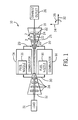
- FIG. 1 is a schematic block diagram of an embodiment of a gas turbine system 10 having turbine blades 22 with improved tip shrouds.
- the gas turbine system 10 includes a compressor 12, combustors 14 having fuel nozzles 16, and a turbine 18.
- the fuel nozzles 16 route a liquid fuel and/or gas fuel, such as natural gas or syngas, into the combustors 14.
- the combustors 14 ignite and combust a fuel-air mixture, and then pass hot pressurized combustion gases 20 (e.g., exhaust) into the turbine 18.
- the turbine blades 22 are coupled to a rotor 24, which is also coupled to several other components throughout the gas turbine system 10, as illustrated.
- the turbine 18 is driven into rotation, which causes the rotor 24 to rotate along a rotational axis 25.
- the combustion gases 20 exit the turbine 18 via an exhaust outlet 26.
- the compressor 12 includes compressor blades 28.
- the compressor blades 28 within the compressor 12 are also coupled to the rotor 24, and rotate as the rotor 24 is driven into rotation by the turbine 18, as described above.
- the compressor blades 28 compress air from an air intake into pressurized air 30, which is routed to the combustors 14, the fuel nozzles 16, and other portions of the gas turbine system 10.
- the fuel nozzles 16 then mix the pressurized air and fuel to produce a suitable fuel-air mixture, which combusts in the combustors 14 to generate the combustion gases 20 to drive the turbine 18.
- the rotor 24 may be coupled to a load 31, which may be powered via rotation of the rotor 24.
- the load 31 may be any suitable device that may generate power via the rotational output of the gas turbine system 10, such as a power generation plant or an external mechanical load.
- the load 31 may include an electrical generator, a propeller of an airplane, and so forth.
- reference may be made to various directions, such as an axial direction or axis 32, a radial direction or axis 34, and a circumferential direction or axis 36 of the turbine 18.
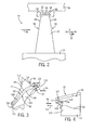
- FIG. 2 is a partial side view, taken within line 2-2 of FIG. 1 , of the turbine 18, illustrating a turbine blade 22 (e.g., airfoil) having a tip shroud 50.
- the tip shroud 50 may serve to block tip leakage between a radial end 52 of the turbine blade 22 and a stationary structural component 54.
- the stationary structural component 54 may be a turbine casing, housing, shroud, and so forth.
- the tip shroud 50 may help block a fluid flow 56 (e.g., of the combustion gases 20 from the combustor 14) within the turbine 18 from passing from a pressure side 58 to a suction side 60 of the turbine blade 22 through a clearance 62 between the radial end 52 of the turbine blade 22 and the stationary structural component 54. Furthermore, the tip shroud 50 may also dampen vibrations in the turbine blade 22. In certain embodiments, the tip shroud 50 may also include a labyrinth seal 64, which further blocks the fluid flow 56 from passing from the pressure side 58 to the suction side 60 through the clearance 62.
- the labyrinth seal 64 includes a single rail 66, which extends in the radial direction 34 towards the stationary structural component 54.
- the labyrinth seal 64 may include multiple rails 66.
- the tip shroud 50 is disposed on the radial end 52 of the turbine blade 22. Specifically, the tip shroud 50 extends laterally from an outer surface 68 of the turbine blade 22 about a perimeter of the turbine blade 22. As discussed in detail below, the geometry of the tip shroud 50 may vary. For example, different portions of the tip shroud 50, e.g., a leading edge portion, a trailing edge portion, a suction side portion, and a pressure side portion, may have different contours, shapes, etc. In other words, different portions of the tip shroud 50 may extend laterally from the outer surface 68 of the turbine blade 22 by different amounts. For example, as discussed below, the tip shroud 50 may have asymmetric pressure and suction sides.
- FIG. 3 is a cross-sectional bottom view, taken along line 3-3 of FIG. 2 , of the tip shroud 50, illustrating a leading edge overhang 100 of the tip shroud 50.
- the cross-sectional view illustrated in FIG. 3 depicts the side of the tip shroud 50 that faces away from the stationary structural component 54 (e.g., the tip shroud 50 as viewed from the rotor 24).
- the tip shroud 50 extends laterally from the outer surface 68 of the turbine blade 22 (e.g., airfoil).
- the tip shroud 50 includes various portions, which may have different geometries, contours, or shapes.
- the tip shroud 50 includes a suction side portion 102 and a pressure side portion 104.
- the suction side portion 102 of the tip shroud 50 extends laterally from the suction side 60 of the turbine blade 22.
- the pressure side portion 104 extends laterally from the pressure side 58 of the turbine blade 22.
- the suction side 60 and the pressure side 58 of the turbine blade may be separated (i.e., divided) by a mean camber line 106 of the turbine blade 22.
- the mean camber line 106 is generally defined by a spanwise average width 108 of the turbine blade 22.
- the tip shroud 50 in the illustrated embodiment includes the leading edge overhang 100. That is, the leading edge overhang 100 is a lateral extension of the tip shroud 50 from the turbine blade 22 at a leading edge 110 of the turbine blade 22. More specifically, the leading edge overhang 100 extends laterally from the turbine blade 22 and ahead of the leading edge 110 along the mean camber line 106 of the turbine blade 22. As discussed in detail below, the leading edge overhang 100 may help block the fluid flow 56 from passing over the radial end 52 of the turbine blade 22 through the clearance 62 between the radial end 52 of the turbine blade 22 and the stationary structural component 54. In this manner, vortex flow generation and pressure mixing (i.e., pressure mixing between the suction side 60 and the pressure side 58 of the turbine blade 22) may be reduced, thereby improving the efficiency of the turbine blade 22.
- vortex flow generation and pressure mixing i.e., pressure mixing between the suction side 60 and the pressure side 58 of the turbine blade 22
- the leading edge overhang 100 extends a distance 112 ahead of the leading edge 110 of the turbine blade 22.
- the distance 112 of the leading edge overhang 100 may be expressed as a percentage of a total chord length 114 of the turbine blade 22.
- the total chord length 114 of the turbine blade 22 may be defined as a distance between the leading edge 110 of the turbine blade 22 and a trailing edge 116 of the turbine blade 22 along the mean camber line 106.
- the distance 112 of the leading edge overhang 100 may be approximately 1 to 20, 2 to 18, 3 to 16, 4 to 14, 5 to 12 or 6 to 10 percent of the total chord length 114 of the turbine blade 22.
- the leading edge overhang 100 may have an asymmetric geometry.
- the leading edge overhang 100 may be asymmetric about the mean camber line 106 (i.e., the leading edge overhang 100 may include asymmetric pressure side and suction side portions).
- the trailing edge 116 may include an extension or overhang similar to the leading edge overhang 100.
- the trailing edge 116 may include a trailing edge overhang 118, which may extend behind the trailing edge 116 of the turbine blade 22.
- FIG. 4 is a perspective view, taking within line 4-4 of FIG. 3 , of the leading edge overhang 100 of the tip shroud 50 extending over, and ahead of, the leading edge 110 of the turbine blade 22 and generally in a negative axial direction 111 of the turbine 18.
- the negative axial direction 111 is generally in an upstream direction along the axis 32 of the turbine 18.
- the leading edge overhang 100 may help block the fluid flow 56 from passing over the radial end 52 of the turbine blade 22.
- the leading edge overhang 100 may direct the fluid flow 56 down the turbine blade 22, as indicated by arrow 120.
- the leading edge overhang 100 may direct the fluid flow 56 across the pressure side 58 of the turbine blade 22, as indicated by arrow 122. In this manner, fluid flow 56 leakage over the radial end 52 of the turbine blade 22 is reduced, thereby improving the efficiency of the turbine 18.
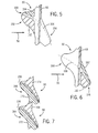
- FIG. 5 is a top view of the tip shroud 50, illustrating a leading edge portion 150 of the tip shroud 50 with asymmetrical sides.
- the top view illustrated in FIG. 5 depicts the side of the tip shroud 50 that faces toward the stationary structural component 54.
- the leading edge portion 150 of the tip shroud 50 has a pressure side portion 152 (i.e. corresponding to the pressure side 58 of the turbine blade 22) that is asymmetrical to a suction side portion 154 (i.e. corresponding to the suction side 60 of the turbine blade 22) of the tip shroud 50.
- the leading edge portion 150 of the tip shroud 50 is generally separated from a trailing edge portion 156 of the tip shroud 50 by the rail 66 of the labyrinth seal 64.
- the leading edge portion 150 may include the leading edge overhang 100 discussed above. In other words, the leading edge overhang 100 may extend over the leading edge 110 of the turbine blade 22 and may be asymmetrical about the mean camber line 106.
- the pressure side portion 152 and the suction side portion 154 of the leading edge portion 150 of the tip shroud 50 are asymmetrical.
- the pressure side portion 152 is larger than the suction side portion 154.
- the pressure side portion 152 of the tip shroud 50 has a substantially greater surface area extending laterally from the outer surface 68 of the turbine blade 22 than the suction side portion 154 of the tip shroud 50.
- the surface area of the pressure side portion 152 of the tip shroud 50 may be approximately 5 to 500, 10 to 400, 15 to 300, 20 to 250, 25 to 200, 30 to 150, 40 to 100, or 45 to 50 percent larger than the surface area of the suction side portion 154.
- the pressure side portion 152 of the tip shroud 50 may block the fluid flow 56 within the turbine 18 from passing over the radial end 52 of the turbine blade 22, thereby reducing over tip leakage. Consequently, the turbine blade 22 and turbine 18 may experience improved efficiency. Additionally, the size of the suction side portion 154 of the tip shroud 50 may be reduced, thereby decreasing the total weight of the tip shroud 50. As will be appreciated, decreasing the overall weight of the tip shroud 50 may reduce the centrifugal mechanical load on the turbine blade 22 and the rotor 24 when the turbine 18 is in operation.
- FIG. 6 is a top view of the tip shroud 50, illustrating the trailing edge portion 156 of the tip shroud 50 with asymmetrical sides. More specifically, the trailing edge portion 156 of the tip shroud 50 has a pressure side portion 160 (i.e. corresponding to the pressure side 58 of the turbine blade 22) that is asymmetrical to a suction side portion 162 (i.e. corresponding to the suction side 60 of the turbine blade 22) of the tip shroud 50. As similarly discussed above, the pressure side portion 160 and the suction side portion 162 of the trailing edge portion 156 are separated by the mean camber line 106 of the turbine blade 22. As with the leading edge portion 150 shown in FIG. 5 , the trailing edge portion 156 of the tip shroud 50 in the illustrated embodiment is generally separated from the leading edge portion 150 of the tip shroud 50 by the rail 66 of the labyrinth seal 64.
- the pressure side portion 160 and the suction side portion 162 of the trailing edge portion 156 of the tip shroud 50 are asymmetrical about the mean camber line 106 of the turbine blade 22. More specifically, in the illustrated embodiment, the pressure side portion 160 is larger than the suction side portion 162. In other words, the pressure side portion 160 of the trailing edge portion 156 of the tip shroud 50 has a greater surface area extending laterally from the outer surface 68 of the turbine blade 22 than the suction side portion 162 of the trailing edge portion 156 of the tip shroud 50.
- the surface area of the pressure side portion 160 of the tip shroud 50 may be approximately 5 to 400, 10 to 350, 15 to 300, 20 to 250, 25 to 200, 30 to 150, 40 to 100, or 45 to 50 percent larger than the surface area of the suction side portion 162.
- the pressure side portion 160 of the tip shroud 50 may block the fluid flow 56 within the turbine 18 from passing over the radial end 52 of the turbine blade 22. Additionally, the fluid flow 56 interaction with leakage flow over the rail 66 may be reduced, potentially resulting in reduced mixing loss. Consequently, the turbine blade 22 and the turbine 18 may experience improved efficiency.
- the size of the suction side portion 162 of the tip shroud 50 may be reduced, thereby decreasing the total weight of the tip shroud 50.
- decreasing the overall weight of the tip shroud 50 may reduce the centrifugal mechanical load on the turbine blade 22 and the rotor 24 when the turbine 18 is in operation.
- FIG. 7 is a top view of two adjacent tip shrouds 50, illustrating contact between the two tip shrouds 50. More specifically, a first tip shroud 164 may be positioned on one turbine blade 22, and a second tip shroud 166 may be positioned on an adjacent turbine blade 22 of the same stage or row of turbine blades 22 coupled to the rotor 24. As shown, the two adjacent tip shrouds 50 (e.g., the first tip shroud 164 and the second tip shroud 166) are in contact with one another, as they are on adjacent turbine blades 22. For example, a suction side portion 168 of the first tip shroud 164 makes physical contact with a pressure side portion 170 of the second tip shroud 166. As will be appreciated, tip shrouds 50 of the turbine blade 22 may have physical contact with tip shrouds 50 of adjacent turbine blades 22 to improve mechanical stiffness of the turbine blades 22.
- the adjacent tip shrouds 50 may have asymmetrical sides, in the manner described above.
- the first tip shroud 164 has a pressure side portion 172 which is asymmetrical to and has a greater surface area than the suction side portion 168 of the first tip shroud 164.
- the pressure side portion 170 of the second tip shroud 166 may be asymmetrical to and have a smaller surface area than a suction side portion 174 of the second tip shroud 166.
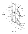
- FIG. 8 is a top view of an embodiment of two tip shrouds 50, illustrating the trailing edge portion 156 of each tip shroud 50 having asymmetrical sides. As shown, the two tip shrouds 50 contact one another, as similarly described above with regard to FIG. 7 . That is, a first tip shroud 180 may be positioned on one turbine blade 22, and a second tip shroud 182 may be positioned on another adjacent turbine blade 22 of the same stage or row. Additionally, the illustrated embodiment of the tip shrouds 50 includes scalloped portions 180, and labyrinth seals 64 of each tip shroud 50 includes two rails 66 (e.g., a first rail 183 and a second rail 184).
- two rails 66 e.g., a first rail 183 and a second rail 184
- the tip shroud 50 may include the scalloped portions 180 to further reduce the weight of the tip shroud 50, and thereby reduce the centrifugal mechanical load on the turbine blade 22 and the rotor 24 when the turbine 18 is in operation. More specifically, the scalloped portions 180 may be formed by forming indentions or notches in the tip shroud 50, as shown. In other words, material from the tip shroud 50 may be removed to form the scalloped portions 180, thereby reducing the weight of the tip shroud 50.
- each tip shroud includes a pressure side portion 186 (i.e. corresponding to the pressure side 58 of the turbine blade 22) and a suction side portion 188 (i.e. corresponding to the suction side 60 of the turbine blade 22), where the pressure side portion 186 and the suction side portion 188 are asymmetrical about the mean camber line 106 of the turbine blade 22.
- the pressure side portion 186 has a greater surface area than the suction side portion 188. In this manner, the pressure side portion 186 of each tip shroud 50 may block the fluid flow 56 within the turbine 18 from passing over the radial end 52 of each turbine blade 22.
- the fluid flow 56 interaction with leakage flow over the rails 66 may be reduced, potentially resulting in reduced mixing loss. Consequently, the turbine blade 22 and the turbine 18 may experience improved efficiency. Furthermore, the size of the suction side portion 188 of the tip shroud 50 may be reduced, thereby decreasing the total weight of the tip shroud 50. As will be appreciated, decreasing the overall weight of the tip shroud 50 may reduce the centrifugal mechanical load on the turbine blade 22 and the rotor 24 when the turbine 18 is in operation.
- the two tip shrouds 50 in the illustrated embodiment are in contact with one another, which may improve the mechanical stiffness of the turbine blades 22.
- the two tip shrouds 50 have substantially full coverage between the first and second rails 183 and 184 of each tip shroud 50.
- a suction side surface 190 of the first tip shroud 180 between the first and second rails 183 and 184 of the first tip shroud 180 is substantially fully covered.
- a pressure side surface 192 of the second tip shroud 182 is substantially fully covered between the first and second rails 183 and 184 of the second tip shroud 182.
- the respective surface areas of a pressure side 194 and a suction side 196 of the tip shroud 50 may be substantially fully covered (e.g., similarly sized surface areas) to form a full cylindrical/conical ring over the turbine blade 22 tip.
- the surface area of the pressure side 194 may be greater than the surface area of the suction side 196 upstream of the second rail 184.
- the respective surface areas of the pressure side and the suction side of the tip shroud 50 may be asymmetrical.
- the trailing edge portion 156 e.g., the portion of the tip shroud 50 aft of the second rail 184
- the suction side portion 188 may have a cut-out or other portion removed, thereby decreasing the surface area of the suction side portion 188.
- the pressure side portion 186 may not have a cut-out or other portion removed.
- a pressure side surface 198 of the trailing edge portion 156 of each tip shroud 50 is generally parallel with the mean camber line 106 of each tip shroud 50 at the trailing edge portion 156.
- the pressure side surface 198 of the trailing edge portion 156 may be formed at an angle 200 relative to the mean camber line 106 at the trailing edge portion 156, as indicated by dashed line 202.
- the angle 200 may be approximately 0 to 75, 5 to 60, 10 to 45, or 15 to 30 degrees.
- the angle 200 may be selected to achieve a desired mechanical or aerodynamic performance.
- embodiments of the tip shroud 50 described above may include one or more features such as the leading edge overhang 100.
- the tip shroud 50 may include the leading edge portion 150 with asymmetric pressure and suction portions 152 and 154.
- the tip shroud may include the trailing edge portion 156 with asymmetric pressure and suction portions 160 and 162.
- these improved geometries may help reduce the weight of the tip shroud 50 while still blocking the fluid flow 56 from passing over the radial end 52 of the turbomachine blade 22. In this manner, the performance of the turbomachine blade 22 is improved, while reducing the centrifugal mechanical load on the turbomachine blade 22 and the rotor 24, thereby improving the overall efficiency of the turbomachine 18.
Landscapes
- Engineering & Computer Science (AREA)
- Mechanical Engineering (AREA)
- General Engineering & Computer Science (AREA)
- Physics & Mathematics (AREA)
- Fluid Mechanics (AREA)
- Turbine Rotor Nozzle Sealing (AREA)
Abstract

Description
- The subject matter disclosed herein relates to turbomachines, and, more particularly, to improved tip shroud geometries for a turbomachine blade.
- Turbomachines include compressors and turbines, such as gas turbines, steam turbines, and hydro turbines. Generally, turbomachines include a rotor, which may be a shaft or drum, to which turbomachine blades are attached. Certain turbomachine blades may include tip shrouds to meet structural and/or performance requirements. For example, the tip shroud of a turbomachine blade may reduce leakage or cross flow from a pressure side (e.g., a concave face) to a suction side (e.g., a convex face) side of the turbomachine blade. However, the tip shroud may be subjected to centrifugal loading, which may cause elevated stresses at the root of the tip shroud and potentially reduce the useful life of the turbomachine blade and/or the rotor.
- Certain embodiments commensurate in scope with the originally claimed invention are summarized below. These embodiments are not intended to limit the scope of the claimed invention, but rather these embodiments are intended only to provide a brief summary of possible forms of the invention. Indeed, the invention may encompass a variety of forms that may be similar to or different from the embodiments set forth below.
- In a first aspect, the invention resides in a turbomachine blade having a tip shroud. The tip shroud includes a leading edge portion, where a first pressure side portion of the leading edge portion has a greater surface area than a first suction side portion of the leading edge portion. The tip shroud further includes a trailing edge portion, where a second pressure side portion of the trailing edge portion has a greater surface area than a second suction side portion of the trailing edge portion.
- In another aspect, the invention resides in a turbomachine blade tip shroud having a pressure side portion and a suction side portion. The pressure side portion and the suction side portion are divided by a mean camber line of a turbomachine blade, and the pressure side portion has a greater surface area than the suction side portion.
- In a third aspect, the invention resides in a turbine blade including a turbine blade tip shroud. The turbine blade tip shroud includes a pressure side portion and a suction side portion, where the pressure side portion and the suction side portion are divided by a mean camber line of the turbine blade, and the pressure side portion has a larger surface area than the suction side portion.
- Embodiments of the present invention will now be described, by way of example only, with reference to the accompanying drawings in which:
-
FIG. 1 is a schematic block diagram of an embodiment of a gas turbine system having blades with improved tip shrouds; -
FIG. 2 is a partial side view, taken within line 2-2 ofFIG. 1 , of a turbomachine (e.g., a turbine) having a turbomachine blade with a tip shroud, in accordance with embodiments of the present disclosure; -
FIG. 3 is a cross-sectional bottom view, taken along line 3-3 ofFIG. 2 , of a turbomachine blade, illustrating a tip shroud, in accordance with embodiments of the present disclosure; -
FIG. 4 is a perspective view of a tip shroud, illustrating a leading edge overhang of the tip shroud, in accordance with embodiments of the present disclosure; -
FIG. 5 is a top view of a tip shroud, illustrating a leading edge portion of the tip shroud with asymmetrical sides, in accordance with embodiments of the present disclosure; -
FIG. 6 is a top view of a tip shroud, illustrating a trailing edge portion of the tip shroud with asymmetrical sides, in accordance with embodiments of the present disclosure; -
FIG. 7 is a top view of adjacent tip shrouds in contact with one another, in accordance with embodiments of the present disclosure; and -
FIG. 8 is a top view of adjacent scalloped tip shrouds with each tip shroud having two rails, in accordance with embodiments of the present disclosure. - One or more specific embodiments of the present invention will be described below. In an effort to provide a concise description of these embodiments, all features of an actual implementation may not be described in the specification. It should be appreciated that in the development of any such actual implementation, as in any engineering or design project, numerous implementation-specific decisions must be made to achieve the developers' specific goals, such as compliance with system-related and business-related constraints, which may vary from one implementation to another. Moreover, it should be appreciated that such a development effort might be complex and time consuming, but would nevertheless be a routine undertaking of design, fabrication, and manufacture for those of ordinary skill having the benefit of this disclosure.
- When introducing elements of various embodiments of the present invention, the articles "a," "an," "the," and "said" are intended to mean that there are one or more of the elements. The terms "comprising," "including," and "having" are intended to be inclusive and mean that there may be additional elements other than the listed elements.
- The disclosed embodiments include improved geometries for a turbomachine blade tip shroud. Specifically, the tip shrouds described below may include various geometric features such as a leading edge overhang, which may have asymmetric pressure and suction sides. Additionally, the tip shroud may include geometric features such as asymmetric suction sides and pressure sides at the leading edge and/or trailing edge. As described in detail below, one or more of these geometric features may improve the efficiency of the turbomachine blade or the turbomachine as a whole. Furthermore, the disclosed geometric features may improve the useful life and longevity of the turbomachine blade or turbomachine as a whole. For example, in certain embodiments, the disclosed tip shroud geometries may reduce the weight of the tip shroud, thereby reducing the centrifugal mechanical load on the turbomachine blade. In this manner, stresses in the tip shroud and turbomachine blade may be reduced. Additionally, the asymmetric tip shroud and/or scalloping techniques described below may be an improvement over symmetric tip shroud techniques, which may reduce the adverse impact of scalloped tip shrouds on turbomachine performance. While the disclosed improved tip shroud geometries may be utilized with turbomachine blades of a variety of turbomachines (e.g., turbines and compressors), the following discussion describes improved tip shrouds in the context of a turbine, such as a gas turbine or a steam turbine. However, it is important to note that the following discussion is not intended to limit the application of the disclosed improved tip shrouds to turbines.
- Turning now to the drawings,
FIG. 1 is a schematic block diagram of an embodiment of agas turbine system 10 havingturbine blades 22 with improved tip shrouds. Thegas turbine system 10 includes acompressor 12,combustors 14 havingfuel nozzles 16, and aturbine 18. The fuel nozzles 16 route a liquid fuel and/or gas fuel, such as natural gas or syngas, into thecombustors 14. Thecombustors 14 ignite and combust a fuel-air mixture, and then pass hot pressurized combustion gases 20 (e.g., exhaust) into theturbine 18. Theturbine blades 22 are coupled to arotor 24, which is also coupled to several other components throughout thegas turbine system 10, as illustrated. As thecombustion gases 20 pass through theturbine blades 22 in theturbine 18, theturbine 18 is driven into rotation, which causes therotor 24 to rotate along arotational axis 25. Eventually, thecombustion gases 20 exit theturbine 18 via anexhaust outlet 26. - In the illustrated embodiment, the
compressor 12 includescompressor blades 28. Thecompressor blades 28 within thecompressor 12 are also coupled to therotor 24, and rotate as therotor 24 is driven into rotation by theturbine 18, as described above. As thecompressor blades 28 rotate within thecompressor 12, thecompressor blades 28 compress air from an air intake into pressurizedair 30, which is routed to thecombustors 14, thefuel nozzles 16, and other portions of thegas turbine system 10. Thefuel nozzles 16 then mix the pressurized air and fuel to produce a suitable fuel-air mixture, which combusts in thecombustors 14 to generate thecombustion gases 20 to drive theturbine 18. Further, therotor 24 may be coupled to aload 31, which may be powered via rotation of therotor 24. For example, theload 31 may be any suitable device that may generate power via the rotational output of thegas turbine system 10, such as a power generation plant or an external mechanical load. For instance, theload 31 may include an electrical generator, a propeller of an airplane, and so forth. In the following discussion, reference may be made to various directions, such as an axial direction oraxis 32, a radial direction oraxis 34, and a circumferential direction oraxis 36 of theturbine 18. -
FIG. 2 is a partial side view, taken within line 2-2 ofFIG. 1 , of theturbine 18, illustrating a turbine blade 22 (e.g., airfoil) having atip shroud 50. As will be appreciated, thetip shroud 50 may serve to block tip leakage between aradial end 52 of theturbine blade 22 and a stationarystructural component 54. For example, the stationarystructural component 54 may be a turbine casing, housing, shroud, and so forth. In other words, thetip shroud 50 may help block a fluid flow 56 (e.g., of thecombustion gases 20 from the combustor 14) within theturbine 18 from passing from apressure side 58 to asuction side 60 of theturbine blade 22 through aclearance 62 between theradial end 52 of theturbine blade 22 and the stationarystructural component 54. Furthermore, thetip shroud 50 may also dampen vibrations in theturbine blade 22. In certain embodiments, thetip shroud 50 may also include alabyrinth seal 64, which further blocks thefluid flow 56 from passing from thepressure side 58 to thesuction side 60 through theclearance 62. In the illustrated embodiment, thelabyrinth seal 64 includes asingle rail 66, which extends in theradial direction 34 towards the stationarystructural component 54. In other embodiments, such as the embodiment illustrated inFIG. 7 , thelabyrinth seal 64 may includemultiple rails 66. - As mentioned above, the
tip shroud 50 is disposed on theradial end 52 of theturbine blade 22. Specifically, thetip shroud 50 extends laterally from anouter surface 68 of theturbine blade 22 about a perimeter of theturbine blade 22. As discussed in detail below, the geometry of thetip shroud 50 may vary. For example, different portions of thetip shroud 50, e.g., a leading edge portion, a trailing edge portion, a suction side portion, and a pressure side portion, may have different contours, shapes, etc. In other words, different portions of thetip shroud 50 may extend laterally from theouter surface 68 of theturbine blade 22 by different amounts. For example, as discussed below, thetip shroud 50 may have asymmetric pressure and suction sides. -
FIG. 3 is a cross-sectional bottom view, taken along line 3-3 ofFIG. 2 , of thetip shroud 50, illustrating aleading edge overhang 100 of thetip shroud 50. As such, the cross-sectional view illustrated inFIG. 3 depicts the side of thetip shroud 50 that faces away from the stationary structural component 54 (e.g., thetip shroud 50 as viewed from the rotor 24). As mentioned above, thetip shroud 50 extends laterally from theouter surface 68 of the turbine blade 22 (e.g., airfoil). Additionally, thetip shroud 50 includes various portions, which may have different geometries, contours, or shapes. For example, thetip shroud 50 includes asuction side portion 102 and apressure side portion 104. As will be appreciated, thesuction side portion 102 of thetip shroud 50 extends laterally from thesuction side 60 of theturbine blade 22. Similarly, thepressure side portion 104 extends laterally from thepressure side 58 of theturbine blade 22. As shown, thesuction side 60 and thepressure side 58 of the turbine blade may be separated (i.e., divided) by amean camber line 106 of theturbine blade 22. Themean camber line 106 is generally defined by a spanwise average width 108 of theturbine blade 22. - As mentioned above, the
tip shroud 50 in the illustrated embodiment includes theleading edge overhang 100. That is, the leadingedge overhang 100 is a lateral extension of thetip shroud 50 from theturbine blade 22 at aleading edge 110 of theturbine blade 22. More specifically, the leadingedge overhang 100 extends laterally from theturbine blade 22 and ahead of theleading edge 110 along themean camber line 106 of theturbine blade 22. As discussed in detail below, the leadingedge overhang 100 may help block thefluid flow 56 from passing over theradial end 52 of theturbine blade 22 through theclearance 62 between theradial end 52 of theturbine blade 22 and the stationarystructural component 54. In this manner, vortex flow generation and pressure mixing (i.e., pressure mixing between thesuction side 60 and thepressure side 58 of the turbine blade 22) may be reduced, thereby improving the efficiency of theturbine blade 22. - In the illustrated embodiment, the leading
edge overhang 100 extends adistance 112 ahead of theleading edge 110 of theturbine blade 22. Thedistance 112 of theleading edge overhang 100 may be expressed as a percentage of atotal chord length 114 of theturbine blade 22. As will be appreciated, thetotal chord length 114 of theturbine blade 22 may be defined as a distance between theleading edge 110 of theturbine blade 22 and a trailing edge 116 of theturbine blade 22 along themean camber line 106. For example, thedistance 112 of theleading edge overhang 100 may be approximately 1 to 20, 2 to 18, 3 to 16, 4 to 14, 5 to 12 or 6 to 10 percent of thetotal chord length 114 of theturbine blade 22. Additionally, in certain embodiments, the leadingedge overhang 100 may have an asymmetric geometry. In other words, as discussed in detail below, the leadingedge overhang 100 may be asymmetric about the mean camber line 106 (i.e., the leadingedge overhang 100 may include asymmetric pressure side and suction side portions). Similarly, in certain embodiments, the trailing edge 116 may include an extension or overhang similar to theleading edge overhang 100. For example, the trailing edge 116 may include a trailingedge overhang 118, which may extend behind the trailing edge 116 of theturbine blade 22. -
FIG. 4 is a perspective view, taking within line 4-4 ofFIG. 3 , of theleading edge overhang 100 of thetip shroud 50 extending over, and ahead of, theleading edge 110 of theturbine blade 22 and generally in a negativeaxial direction 111 of theturbine 18. In other words, the negativeaxial direction 111 is generally in an upstream direction along theaxis 32 of theturbine 18. As previously mentioned, the leadingedge overhang 100 may help block thefluid flow 56 from passing over theradial end 52 of theturbine blade 22. For example, the leadingedge overhang 100 may direct thefluid flow 56 down theturbine blade 22, as indicated byarrow 120. Similarly, the leadingedge overhang 100 may direct thefluid flow 56 across thepressure side 58 of theturbine blade 22, as indicated byarrow 122. In this manner,fluid flow 56 leakage over theradial end 52 of theturbine blade 22 is reduced, thereby improving the efficiency of theturbine 18. -
FIG. 5 is a top view of thetip shroud 50, illustrating aleading edge portion 150 of thetip shroud 50 with asymmetrical sides. As such, the top view illustrated inFIG. 5 (as well asFIGS. 6 and 7 ) depicts the side of thetip shroud 50 that faces toward the stationarystructural component 54. Theleading edge portion 150 of thetip shroud 50 has a pressure side portion 152 (i.e. corresponding to thepressure side 58 of the turbine blade 22) that is asymmetrical to a suction side portion 154 (i.e. corresponding to thesuction side 60 of the turbine blade 22) of thetip shroud 50. As similarly discussed above, thepressure side portion 152 and thesuction side portion 154 of theleading edge portion 150 are separated by themean camber line 106 of theturbine blade 22. In the illustrated embodiment, the leadingedge portion 150 of thetip shroud 50 is generally separated from a trailingedge portion 156 of thetip shroud 50 by therail 66 of thelabyrinth seal 64. In certain embodiments, the leadingedge portion 150 may include theleading edge overhang 100 discussed above. In other words, the leadingedge overhang 100 may extend over theleading edge 110 of theturbine blade 22 and may be asymmetrical about themean camber line 106. - As previously mentioned, the
pressure side portion 152 and thesuction side portion 154 of theleading edge portion 150 of thetip shroud 50 are asymmetrical. For example, in the illustrated embodiment, thepressure side portion 152 is larger than thesuction side portion 154. In other words, thepressure side portion 152 of thetip shroud 50 has a substantially greater surface area extending laterally from theouter surface 68 of theturbine blade 22 than thesuction side portion 154 of thetip shroud 50. For example, in certain embodiments, the surface area of thepressure side portion 152 of thetip shroud 50 may be approximately 5 to 500, 10 to 400, 15 to 300, 20 to 250, 25 to 200, 30 to 150, 40 to 100, or 45 to 50 percent larger than the surface area of thesuction side portion 154. In this manner, thepressure side portion 152 of thetip shroud 50 may block thefluid flow 56 within theturbine 18 from passing over theradial end 52 of theturbine blade 22, thereby reducing over tip leakage. Consequently, theturbine blade 22 andturbine 18 may experience improved efficiency. Additionally, the size of thesuction side portion 154 of thetip shroud 50 may be reduced, thereby decreasing the total weight of thetip shroud 50. As will be appreciated, decreasing the overall weight of thetip shroud 50 may reduce the centrifugal mechanical load on theturbine blade 22 and therotor 24 when theturbine 18 is in operation. -
FIG. 6 is a top view of thetip shroud 50, illustrating the trailingedge portion 156 of thetip shroud 50 with asymmetrical sides. More specifically, the trailingedge portion 156 of thetip shroud 50 has a pressure side portion 160 (i.e. corresponding to thepressure side 58 of the turbine blade 22) that is asymmetrical to a suction side portion 162 (i.e. corresponding to thesuction side 60 of the turbine blade 22) of thetip shroud 50. As similarly discussed above, thepressure side portion 160 and thesuction side portion 162 of the trailingedge portion 156 are separated by themean camber line 106 of theturbine blade 22. As with theleading edge portion 150 shown inFIG. 5 , the trailingedge portion 156 of thetip shroud 50 in the illustrated embodiment is generally separated from theleading edge portion 150 of thetip shroud 50 by therail 66 of thelabyrinth seal 64. - As previously mentioned, the
pressure side portion 160 and thesuction side portion 162 of the trailingedge portion 156 of thetip shroud 50 are asymmetrical about themean camber line 106 of theturbine blade 22. More specifically, in the illustrated embodiment, thepressure side portion 160 is larger than thesuction side portion 162. In other words, thepressure side portion 160 of the trailingedge portion 156 of thetip shroud 50 has a greater surface area extending laterally from theouter surface 68 of theturbine blade 22 than thesuction side portion 162 of the trailingedge portion 156 of thetip shroud 50. For example, in certain embodiments, the surface area of thepressure side portion 160 of thetip shroud 50 may be approximately 5 to 400, 10 to 350, 15 to 300, 20 to 250, 25 to 200, 30 to 150, 40 to 100, or 45 to 50 percent larger than the surface area of thesuction side portion 162. In this manner, thepressure side portion 160 of thetip shroud 50 may block thefluid flow 56 within theturbine 18 from passing over theradial end 52 of theturbine blade 22. Additionally, thefluid flow 56 interaction with leakage flow over therail 66 may be reduced, potentially resulting in reduced mixing loss. Consequently, theturbine blade 22 and theturbine 18 may experience improved efficiency. Furthermore, the size of thesuction side portion 162 of thetip shroud 50 may be reduced, thereby decreasing the total weight of thetip shroud 50. As will be appreciated, decreasing the overall weight of thetip shroud 50 may reduce the centrifugal mechanical load on theturbine blade 22 and therotor 24 when theturbine 18 is in operation. -
FIG. 7 is a top view of two adjacent tip shrouds 50, illustrating contact between the two tip shrouds 50. More specifically, afirst tip shroud 164 may be positioned on oneturbine blade 22, and asecond tip shroud 166 may be positioned on anadjacent turbine blade 22 of the same stage or row ofturbine blades 22 coupled to therotor 24. As shown, the two adjacent tip shrouds 50 (e.g., thefirst tip shroud 164 and the second tip shroud 166) are in contact with one another, as they are onadjacent turbine blades 22. For example, asuction side portion 168 of thefirst tip shroud 164 makes physical contact with apressure side portion 170 of thesecond tip shroud 166. As will be appreciated, tip shrouds 50 of theturbine blade 22 may have physical contact withtip shrouds 50 ofadjacent turbine blades 22 to improve mechanical stiffness of theturbine blades 22. - The adjacent tip shrouds 50 (e.g., the
first tip shroud 164 and the second tip shroud 166) may have asymmetrical sides, in the manner described above. For example, thefirst tip shroud 164 has apressure side portion 172 which is asymmetrical to and has a greater surface area than thesuction side portion 168 of thefirst tip shroud 164. Similarly, thepressure side portion 170 of thesecond tip shroud 166 may be asymmetrical to and have a smaller surface area than asuction side portion 174 of thesecond tip shroud 166. -
FIG. 8 is a top view of an embodiment of twotip shrouds 50, illustrating the trailingedge portion 156 of eachtip shroud 50 having asymmetrical sides. As shown, the twotip shrouds 50 contact one another, as similarly described above with regard toFIG. 7 . That is, afirst tip shroud 180 may be positioned on oneturbine blade 22, and asecond tip shroud 182 may be positioned on anotheradjacent turbine blade 22 of the same stage or row. Additionally, the illustrated embodiment of the tip shrouds 50 includes scallopedportions 180, and labyrinth seals 64 of eachtip shroud 50 includes two rails 66 (e.g., afirst rail 183 and a second rail 184). As will be appreciated, thetip shroud 50 may include thescalloped portions 180 to further reduce the weight of thetip shroud 50, and thereby reduce the centrifugal mechanical load on theturbine blade 22 and therotor 24 when theturbine 18 is in operation. More specifically, thescalloped portions 180 may be formed by forming indentions or notches in thetip shroud 50, as shown. In other words, material from thetip shroud 50 may be removed to form the scallopedportions 180, thereby reducing the weight of thetip shroud 50. - As shown, the trailing
edge portion 156 of each tip shroud includes a pressure side portion 186 (i.e. corresponding to thepressure side 58 of the turbine blade 22) and a suction side portion 188 (i.e. corresponding to thesuction side 60 of the turbine blade 22), where thepressure side portion 186 and thesuction side portion 188 are asymmetrical about themean camber line 106 of theturbine blade 22. As similarly discussed above with respect toFIG. 6 , thepressure side portion 186 has a greater surface area than thesuction side portion 188. In this manner, thepressure side portion 186 of eachtip shroud 50 may block thefluid flow 56 within theturbine 18 from passing over theradial end 52 of eachturbine blade 22. Additionally, thefluid flow 56 interaction with leakage flow over therails 66 may be reduced, potentially resulting in reduced mixing loss. Consequently, theturbine blade 22 and theturbine 18 may experience improved efficiency. Furthermore, the size of thesuction side portion 188 of thetip shroud 50 may be reduced, thereby decreasing the total weight of thetip shroud 50. As will be appreciated, decreasing the overall weight of thetip shroud 50 may reduce the centrifugal mechanical load on theturbine blade 22 and therotor 24 when theturbine 18 is in operation. - Additionally, as mentioned above, the two
tip shrouds 50 in the illustrated embodiment are in contact with one another, which may improve the mechanical stiffness of theturbine blades 22. For example, the twotip shrouds 50 have substantially full coverage between the first andsecond rails tip shroud 50. In other words, asuction side surface 190 of thefirst tip shroud 180 between the first andsecond rails first tip shroud 180 is substantially fully covered. Similarly, apressure side surface 192 of thesecond tip shroud 182 is substantially fully covered between the first andsecond rails second tip shroud 182. In certain embodiments, upstream of the second rail 184 (e.g., between the first andsecond rails 183 and 184), the respective surface areas of apressure side 194 and asuction side 196 of thetip shroud 50 may be substantially fully covered (e.g., similarly sized surface areas) to form a full cylindrical/conical ring over theturbine blade 22 tip. In other embodiments, the surface area of thepressure side 194 may be greater than the surface area of thesuction side 196 upstream of thesecond rail 184. - Conversely, aft of the
second rail 184, the respective surface areas of the pressure side and the suction side of thetip shroud 50 may be asymmetrical. Specifically, as described above, the trailing edge portion 156 (e.g., the portion of thetip shroud 50 aft of the second rail 184) may be scalloped such that thepressure side portion 186 has a greater surface area than thesuction side portion 188. In other words, thesuction side portion 188 may have a cut-out or other portion removed, thereby decreasing the surface area of thesuction side portion 188. By contrast, thepressure side portion 186 may not have a cut-out or other portion removed. As a result, in the illustrated embodiment of the trailingedge portions 156 of each tip shroud 50 (e.g., aft of the second rail 184), thesuction side surface 190 of thefirst tip shroud 180 is not in substantially full contact with thepressure side surface 192 of thesecond tip shroud 182. Furthermore, in the illustrated embodiment, apressure side surface 198 of the trailingedge portion 156 of eachtip shroud 50 is generally parallel with themean camber line 106 of eachtip shroud 50 at the trailingedge portion 156. However, in other embodiments, thepressure side surface 198 of the trailingedge portion 156 may be formed at anangle 200 relative to themean camber line 106 at the trailingedge portion 156, as indicated by dashedline 202. For example, theangle 200 may be approximately 0 to 75, 5 to 60, 10 to 45, or 15 to 30 degrees. As will be appreciated, theangle 200 may be selected to achieve a desired mechanical or aerodynamic performance. - As discussed in detail above, the disclosed embodiments are directed towards an improved geometry for a turbomachine
blade tip shroud 50. More specifically, embodiments of thetip shroud 50 described above may include one or more features such as theleading edge overhang 100. Furthermore, thetip shroud 50 may include theleading edge portion 150 with asymmetric pressure andsuction portions edge portion 156 with asymmetric pressure andsuction portions tip shroud 50 while still blocking thefluid flow 56 from passing over theradial end 52 of theturbomachine blade 22. In this manner, the performance of theturbomachine blade 22 is improved, while reducing the centrifugal mechanical load on theturbomachine blade 22 and therotor 24, thereby improving the overall efficiency of theturbomachine 18. - This written description uses examples to disclose the invention, including the best mode, and also to enable any person skilled in the art to practice the invention, including making and using any devices or systems and performing any incorporated methods. The patentable scope of the invention is defined by the claims, and may include other examples that occur to those skilled in the art. Such other examples are intended to be within the scope of the claims if they have structural elements that do not differ from the literal language of the claims, or if they include equivalent structural elements with insubstantial differences from the literal language of the claims.
Claims (8)
- A turbomachine blade (22), comprising:a tip shroud (50), comprising:a leading edge portion (150), wherein a first pressure side portion (152) of the leading edge portion (150) has a substantially greater surface area than a first suction side portion (154) of the leading edge portion (150); anda trailing edge portion (156), wherein a second pressure side portion (160) of the trailing edge portion (156) has a substantially greater surface area than a second suction side portion (162) of the trailing edge portion (156).
- The turbomachine blade of claim 1, wherein the leading edge portion (150) and the trailing edge portion (156) are separated by at least one rail (66) of a labyrinth seal (64).
- The turbomachine blade of claim 1 or 2, wherein the leading edge portion (150) comprises a leading edge overhang (100) extending over a leading edge (110) of the turbomachine blade (22).
- The turbomachine blade of any of claims 1 to 3, wherein a mean camber line (106) of the turbomachine blade (22) extends between the first pressure side portion (152) and the first suction side portion (154).
- The turbomachine blade of any of claims 1 to 4, wherein a mean camber line (106) of the turbomachine blade (22) extends between the second pressure side portion (160) and the second suction side portion (162).
- The turbomachine blade of any of claims 1 to 5, wherein the tip shroud (50) comprises at least one scalloped portion (180).
- A turbomachine having the turbomachine blade, (22) of any of claims 1 to 6.
- The turbomachine of claim 7, wherein the turbomachine is a gas turbine or a steam turbine.
Applications Claiming Priority (1)
| Application Number | Priority Date | Filing Date | Title |
|---|---|---|---|
| US13/355,436 US9109455B2 (en) | 2012-01-20 | 2012-01-20 | Turbomachine blade tip shroud |
Publications (3)
| Publication Number | Publication Date |
|---|---|
| EP2617944A2 true EP2617944A2 (en) | 2013-07-24 |
| EP2617944A3 EP2617944A3 (en) | 2015-08-26 |
| EP2617944B1 EP2617944B1 (en) | 2019-01-09 |
Family
ID=47520856
Family Applications (1)
| Application Number | Title | Priority Date | Filing Date |
|---|---|---|---|
| EP13151449.9A Active EP2617944B1 (en) | 2012-01-20 | 2013-01-16 | Turbomachine blade tip shroud |
Country Status (5)
| Country | Link |
|---|---|
| US (2) | US9109455B2 (en) |
| EP (1) | EP2617944B1 (en) |
| JP (1) | JP6283165B2 (en) |
| CN (1) | CN103216271B (en) |
| RU (1) | RU2648173C2 (en) |
Cited By (1)
| Publication number | Priority date | Publication date | Assignee | Title |
|---|---|---|---|---|
| EP3699399A1 (en) * | 2019-02-21 | 2020-08-26 | MTU Aero Engines GmbH | Blade for a high-speed turbine stage with single sealing element |
Families Citing this family (11)
| Publication number | Priority date | Publication date | Assignee | Title |
|---|---|---|---|---|
| JP6567072B2 (en) * | 2015-03-17 | 2019-08-28 | シーメンス エナジー インコーポレイテッド | Turbine blade with shroud provided with leakage flow control device |
| EP3085890B1 (en) * | 2015-04-22 | 2017-12-27 | Ansaldo Energia Switzerland AG | Blade with tip shroud |
| WO2017018981A1 (en) * | 2015-07-24 | 2017-02-02 | Siemens Aktiengesellschaft | Turbine blade with contoured tip shroud |
| DE102015224375A1 (en) * | 2015-12-04 | 2017-06-08 | Mtu Aero Engines Gmbh | Method of testing a blade unit |
| FR3045710B1 (en) * | 2015-12-21 | 2018-01-26 | Safran Aircraft Engines | ATTACK SHIELD |
| US10648346B2 (en) * | 2016-07-06 | 2020-05-12 | General Electric Company | Shroud configurations for turbine rotor blades |
| US10982554B2 (en) * | 2016-10-28 | 2021-04-20 | General Electric Company | Tip shroud for a turbine engine |
| US10577945B2 (en) * | 2017-06-30 | 2020-03-03 | General Electric Company | Turbomachine rotor blade |
| JP7389574B2 (en) * | 2019-06-28 | 2023-11-30 | 三菱重工航空エンジン株式会社 | aircraft gas turbine |
| US11236620B1 (en) | 2021-02-24 | 2022-02-01 | General Electric Company | Turbine blade tip shroud surface profiles |
| CN117072482B (en) * | 2023-07-27 | 2026-03-24 | 宁波方太厨具有限公司 | Blade assembly, axial flow fan and range hood |
Family Cites Families (28)
| Publication number | Priority date | Publication date | Assignee | Title |
|---|---|---|---|---|
| US2221685A (en) * | 1939-01-18 | 1940-11-12 | Gen Electric | Elastic fluid turbine bucket unit |
| FR1033197A (en) * | 1951-02-27 | 1953-07-08 | Rateau Soc | Vibration dampers for mobile turbo-machine blades |
| US3056583A (en) * | 1960-11-10 | 1962-10-02 | Gen Electric | Retaining means for turbine shrouds and nozzle diaphragms of turbine engines |
| US3867060A (en) * | 1973-09-27 | 1975-02-18 | Gen Electric | Shroud assembly |
| US4177011A (en) | 1976-04-21 | 1979-12-04 | General Electric Company | Bar for sealing the gap between adjacent shroud plates in liquid-cooled gas turbine |
| SU1059222A1 (en) * | 1982-09-01 | 1983-12-07 | Предприятие П/Я В-2285 | Rotary shroud of axial-flow turbo-machine wheel |
| JPS61132702A (en) * | 1984-11-30 | 1986-06-20 | Toshiba Corp | Turbine |
| GB2228540B (en) | 1988-12-07 | 1993-03-31 | Rolls Royce Plc | Cooling of turbine blades |
| GB2251034B (en) * | 1990-12-20 | 1995-05-17 | Rolls Royce Plc | Shrouded aerofoils |
| US5261785A (en) * | 1992-08-04 | 1993-11-16 | General Electric Company | Rotor blade cover adapted to facilitate moisture removal |
| CN1162346A (en) * | 1994-10-26 | 1997-10-15 | 西屋电气公司 | Gas turbine blade with cooled shroud |
| US5482435A (en) * | 1994-10-26 | 1996-01-09 | Westinghouse Electric Corporation | Gas turbine blade having a cooled shroud |
| JPH10266804A (en) * | 1997-03-26 | 1998-10-06 | Mitsubishi Heavy Ind Ltd | Tip shroud blade cavity |
| JP2000018003A (en) * | 1998-06-30 | 2000-01-18 | Toshiba Corp | Turbine blade |
| GB9915648D0 (en) | 1999-07-06 | 1999-09-01 | Rolls Royce Plc | Improvement in or relating to turbine blades |
| WO2003027445A1 (en) * | 2001-09-25 | 2003-04-03 | Alstom Technology Ltd | Joint system for reducing a sealing space in a rotary gas turbine |
| US6893216B2 (en) * | 2003-07-17 | 2005-05-17 | General Electric Company | Turbine bucket tip shroud edge profile |
| US7396205B2 (en) * | 2004-01-31 | 2008-07-08 | United Technologies Corporation | Rotor blade for a rotary machine |
| EP1591626A1 (en) * | 2004-04-30 | 2005-11-02 | Alstom Technology Ltd | Blade for gas turbine |
| EP1591625A1 (en) * | 2004-04-30 | 2005-11-02 | ALSTOM Technology Ltd | Gas turbine blade shroud |
| CH698087B1 (en) * | 2004-09-08 | 2009-05-15 | Alstom Technology Ltd | Blade with shroud element. |
| US7686568B2 (en) * | 2006-09-22 | 2010-03-30 | General Electric Company | Methods and apparatus for fabricating turbine engines |
| US7568882B2 (en) * | 2007-01-12 | 2009-08-04 | General Electric Company | Impingement cooled bucket shroud, turbine rotor incorporating the same, and cooling method |
| US9009965B2 (en) * | 2007-05-24 | 2015-04-21 | General Electric Company | Method to center locate cutter teeth on shrouded turbine blades |
| US8043061B2 (en) * | 2007-08-22 | 2011-10-25 | General Electric Company | Turbine bucket tip shroud edge profile |
| FR2925572B1 (en) * | 2007-12-24 | 2010-02-12 | Snecma Services | METHOD FOR CHOOSING A SECTOR ARRANGEMENT FOR A TURBOMACHINE DISPENSER |
| DE102009042857A1 (en) | 2009-09-24 | 2011-03-31 | Rolls-Royce Deutschland Ltd & Co Kg | Gas turbine with shroud labyrinth seal |
| KR101411177B1 (en) * | 2009-12-07 | 2014-06-23 | 미츠비시 쥬고교 가부시키가이샤 | Turbine and turbine rotor blade |
-
2012
- 2012-01-20 US US13/355,436 patent/US9109455B2/en active Active
-
2013
- 2013-01-16 EP EP13151449.9A patent/EP2617944B1/en active Active
- 2013-01-17 JP JP2013005858A patent/JP6283165B2/en active Active
- 2013-01-18 RU RU2013102138A patent/RU2648173C2/en active
- 2013-01-21 CN CN201310020790.5A patent/CN103216271B/en active Active
-
2015
- 2015-08-12 US US14/824,953 patent/US10253638B2/en active Active
Cited By (2)
| Publication number | Priority date | Publication date | Assignee | Title |
|---|---|---|---|---|
| EP3699399A1 (en) * | 2019-02-21 | 2020-08-26 | MTU Aero Engines GmbH | Blade for a high-speed turbine stage with single sealing element |
| US11230933B2 (en) | 2019-02-21 | 2022-01-25 | MTU Aero Engines AG | Blade for a high-speed turbine stage having a single sealing element |
Also Published As
| Publication number | Publication date |
|---|---|
| US10253638B2 (en) | 2019-04-09 |
| EP2617944B1 (en) | 2019-01-09 |
| US20130189106A1 (en) | 2013-07-25 |
| RU2648173C2 (en) | 2018-03-22 |
| EP2617944A3 (en) | 2015-08-26 |
| US9109455B2 (en) | 2015-08-18 |
| JP6283165B2 (en) | 2018-02-21 |
| CN103216271B (en) | 2017-07-11 |
| CN103216271A (en) | 2013-07-24 |
| US20150345306A1 (en) | 2015-12-03 |
| JP2013148086A (en) | 2013-08-01 |
| RU2013102138A (en) | 2014-07-27 |
Similar Documents
| Publication | Publication Date | Title |
|---|---|---|
| US10253638B2 (en) | Turbomachine blade tip shroud | |
| US8147207B2 (en) | Compressor blade having a ratio of leading edge sweep to leading edge dihedral in a range of 1:1 to 3:1 along the radially outer portion | |
| US9822647B2 (en) | High chord bucket with dual part span shrouds and curved dovetail | |
| US9291061B2 (en) | Turbomachine blade tip shroud with parallel casing configuration | |
| EP2514922A2 (en) | Compressor with blade tip geometry for reducing tip stresses | |
| US8371816B2 (en) | Rotor blades for turbine engines | |
| CN103184898B (en) | Gas turbine nozzle with a flow groove | |
| EP3187688A1 (en) | Rotor blade for a gas turbine and corresponding gas turbine | |
| US8894376B2 (en) | Turbomachine blade with tip flare | |
| US20150345301A1 (en) | Rotor blade cooling flow | |
| CA2880602A1 (en) | Shrouded blade for a gas turbine engine | |
| EP3885533B1 (en) | Rotor blade for a turbomachine and corresponding turbomachine | |
| US10138736B2 (en) | Turbomachine blade tip shroud | |
| US11566530B2 (en) | Turbomachine nozzle with an airfoil having a circular trailing edge | |
| EP3889392B1 (en) | Turbomachine rotor blade with a cooling circuit having an offset rib | |
| CN112943383A (en) | Turbine nozzle with airfoil having curved trailing edge | |
| EP4553274A1 (en) | Turbine engine with a blade assembly having a platform plenum |
Legal Events
| Date | Code | Title | Description |
|---|---|---|---|
| PUAI | Public reference made under article 153(3) epc to a published international application that has entered the european phase |
Free format text: ORIGINAL CODE: 0009012 |
|
| AK | Designated contracting states |
Kind code of ref document: A2 Designated state(s): AL AT BE BG CH CY CZ DE DK EE ES FI FR GB GR HR HU IE IS IT LI LT LU LV MC MK MT NL NO PL PT RO RS SE SI SK SM TR |
|
| AX | Request for extension of the european patent |
Extension state: BA ME |
|
| PUAL | Search report despatched |
Free format text: ORIGINAL CODE: 0009013 |
|
| AK | Designated contracting states |
Kind code of ref document: A3 Designated state(s): AL AT BE BG CH CY CZ DE DK EE ES FI FR GB GR HR HU IE IS IT LI LT LU LV MC MK MT NL NO PL PT RO RS SE SI SK SM TR |
|
| AX | Request for extension of the european patent |
Extension state: BA ME |
|
| RIC1 | Information provided on ipc code assigned before grant |
Ipc: F04D 29/38 20060101ALI20150723BHEP Ipc: F01D 5/22 20060101ALI20150723BHEP Ipc: F01D 5/20 20060101AFI20150723BHEP |
|
| TPAC | Observations filed by third parties |
Free format text: ORIGINAL CODE: EPIDOSNTIPA |
|
| 17P | Request for examination filed |
Effective date: 20160226 |
|
| RBV | Designated contracting states (corrected) |
Designated state(s): AL AT BE BG CH CY CZ DE DK EE ES FI FR GB GR HR HU IE IS IT LI LT LU LV MC MK MT NL NO PL PT RO RS SE SI SK SM TR |
|
| STAA | Information on the status of an ep patent application or granted ep patent |
Free format text: STATUS: EXAMINATION IS IN PROGRESS |
|
| 17Q | First examination report despatched |
Effective date: 20161025 |
|
| GRAP | Despatch of communication of intention to grant a patent |
Free format text: ORIGINAL CODE: EPIDOSNIGR1 |
|
| STAA | Information on the status of an ep patent application or granted ep patent |
Free format text: STATUS: GRANT OF PATENT IS INTENDED |
|
| INTG | Intention to grant announced |
Effective date: 20180815 |
|
| GRAS | Grant fee paid |
Free format text: ORIGINAL CODE: EPIDOSNIGR3 |
|
| GRAA | (expected) grant |
Free format text: ORIGINAL CODE: 0009210 |
|
| STAA | Information on the status of an ep patent application or granted ep patent |
Free format text: STATUS: THE PATENT HAS BEEN GRANTED |
|
| AK | Designated contracting states |
Kind code of ref document: B1 Designated state(s): AL AT BE BG CH CY CZ DE DK EE ES FI FR GB GR HR HU IE IS IT LI LT LU LV MC MK MT NL NO PL PT RO RS SE SI SK SM TR |
|
| REG | Reference to a national code |
Ref country code: GB Ref legal event code: FG4D |
|
| REG | Reference to a national code |
Ref country code: CH Ref legal event code: EP Ref country code: AT Ref legal event code: REF Ref document number: 1087548 Country of ref document: AT Kind code of ref document: T Effective date: 20190115 |
|
| REG | Reference to a national code |
Ref country code: DE Ref legal event code: R096 Ref document number: 602013049443 Country of ref document: DE |
|
| REG | Reference to a national code |
Ref country code: IE Ref legal event code: FG4D |
|
| REG | Reference to a national code |
Ref country code: NL Ref legal event code: MP Effective date: 20190109 |
|
| REG | Reference to a national code |
Ref country code: LT Ref legal event code: MG4D |
|
| PG25 | Lapsed in a contracting state [announced via postgrant information from national office to epo] |
Ref country code: NL Free format text: LAPSE BECAUSE OF FAILURE TO SUBMIT A TRANSLATION OF THE DESCRIPTION OR TO PAY THE FEE WITHIN THE PRESCRIBED TIME-LIMIT Effective date: 20190109 |
|
| REG | Reference to a national code |
Ref country code: AT Ref legal event code: MK05 Ref document number: 1087548 Country of ref document: AT Kind code of ref document: T Effective date: 20190109 |
|
| PG25 | Lapsed in a contracting state [announced via postgrant information from national office to epo] |
Ref country code: LT Free format text: LAPSE BECAUSE OF FAILURE TO SUBMIT A TRANSLATION OF THE DESCRIPTION OR TO PAY THE FEE WITHIN THE PRESCRIBED TIME-LIMIT Effective date: 20190109 Ref country code: FI Free format text: LAPSE BECAUSE OF FAILURE TO SUBMIT A TRANSLATION OF THE DESCRIPTION OR TO PAY THE FEE WITHIN THE PRESCRIBED TIME-LIMIT Effective date: 20190109 Ref country code: NO Free format text: LAPSE BECAUSE OF FAILURE TO SUBMIT A TRANSLATION OF THE DESCRIPTION OR TO PAY THE FEE WITHIN THE PRESCRIBED TIME-LIMIT Effective date: 20190409 Ref country code: ES Free format text: LAPSE BECAUSE OF FAILURE TO SUBMIT A TRANSLATION OF THE DESCRIPTION OR TO PAY THE FEE WITHIN THE PRESCRIBED TIME-LIMIT Effective date: 20190109 Ref country code: PT Free format text: LAPSE BECAUSE OF FAILURE TO SUBMIT A TRANSLATION OF THE DESCRIPTION OR TO PAY THE FEE WITHIN THE PRESCRIBED TIME-LIMIT Effective date: 20190509 Ref country code: SE Free format text: LAPSE BECAUSE OF FAILURE TO SUBMIT A TRANSLATION OF THE DESCRIPTION OR TO PAY THE FEE WITHIN THE PRESCRIBED TIME-LIMIT Effective date: 20190109 Ref country code: PL Free format text: LAPSE BECAUSE OF FAILURE TO SUBMIT A TRANSLATION OF THE DESCRIPTION OR TO PAY THE FEE WITHIN THE PRESCRIBED TIME-LIMIT Effective date: 20190109 |
|
| PG25 | Lapsed in a contracting state [announced via postgrant information from national office to epo] |
Ref country code: LV Free format text: LAPSE BECAUSE OF FAILURE TO SUBMIT A TRANSLATION OF THE DESCRIPTION OR TO PAY THE FEE WITHIN THE PRESCRIBED TIME-LIMIT Effective date: 20190109 Ref country code: IS Free format text: LAPSE BECAUSE OF FAILURE TO SUBMIT A TRANSLATION OF THE DESCRIPTION OR TO PAY THE FEE WITHIN THE PRESCRIBED TIME-LIMIT Effective date: 20190509 Ref country code: HR Free format text: LAPSE BECAUSE OF FAILURE TO SUBMIT A TRANSLATION OF THE DESCRIPTION OR TO PAY THE FEE WITHIN THE PRESCRIBED TIME-LIMIT Effective date: 20190109 Ref country code: BG Free format text: LAPSE BECAUSE OF FAILURE TO SUBMIT A TRANSLATION OF THE DESCRIPTION OR TO PAY THE FEE WITHIN THE PRESCRIBED TIME-LIMIT Effective date: 20190409 Ref country code: RS Free format text: LAPSE BECAUSE OF FAILURE TO SUBMIT A TRANSLATION OF THE DESCRIPTION OR TO PAY THE FEE WITHIN THE PRESCRIBED TIME-LIMIT Effective date: 20190109 Ref country code: GR Free format text: LAPSE BECAUSE OF FAILURE TO SUBMIT A TRANSLATION OF THE DESCRIPTION OR TO PAY THE FEE WITHIN THE PRESCRIBED TIME-LIMIT Effective date: 20190410 |
|
| REG | Reference to a national code |
Ref country code: CH Ref legal event code: PL |
|
| PG25 | Lapsed in a contracting state [announced via postgrant information from national office to epo] |
Ref country code: LU Free format text: LAPSE BECAUSE OF NON-PAYMENT OF DUE FEES Effective date: 20190116 |
|
| REG | Reference to a national code |
Ref country code: DE Ref legal event code: R097 Ref document number: 602013049443 Country of ref document: DE |
|
| REG | Reference to a national code |
Ref country code: BE Ref legal event code: MM Effective date: 20190131 |
|
| REG | Reference to a national code |
Ref country code: IE Ref legal event code: MM4A |
|
| PG25 | Lapsed in a contracting state [announced via postgrant information from national office to epo] |
Ref country code: DK Free format text: LAPSE BECAUSE OF FAILURE TO SUBMIT A TRANSLATION OF THE DESCRIPTION OR TO PAY THE FEE WITHIN THE PRESCRIBED TIME-LIMIT Effective date: 20190109 Ref country code: AT Free format text: LAPSE BECAUSE OF FAILURE TO SUBMIT A TRANSLATION OF THE DESCRIPTION OR TO PAY THE FEE WITHIN THE PRESCRIBED TIME-LIMIT Effective date: 20190109 Ref country code: EE Free format text: LAPSE BECAUSE OF FAILURE TO SUBMIT A TRANSLATION OF THE DESCRIPTION OR TO PAY THE FEE WITHIN THE PRESCRIBED TIME-LIMIT Effective date: 20190109 Ref country code: CZ Free format text: LAPSE BECAUSE OF FAILURE TO SUBMIT A TRANSLATION OF THE DESCRIPTION OR TO PAY THE FEE WITHIN THE PRESCRIBED TIME-LIMIT Effective date: 20190109 Ref country code: RO Free format text: LAPSE BECAUSE OF FAILURE TO SUBMIT A TRANSLATION OF THE DESCRIPTION OR TO PAY THE FEE WITHIN THE PRESCRIBED TIME-LIMIT Effective date: 20190109 Ref country code: SK Free format text: LAPSE BECAUSE OF FAILURE TO SUBMIT A TRANSLATION OF THE DESCRIPTION OR TO PAY THE FEE WITHIN THE PRESCRIBED TIME-LIMIT Effective date: 20190109 Ref country code: IT Free format text: LAPSE BECAUSE OF FAILURE TO SUBMIT A TRANSLATION OF THE DESCRIPTION OR TO PAY THE FEE WITHIN THE PRESCRIBED TIME-LIMIT Effective date: 20190109 Ref country code: AL Free format text: LAPSE BECAUSE OF FAILURE TO SUBMIT A TRANSLATION OF THE DESCRIPTION OR TO PAY THE FEE WITHIN THE PRESCRIBED TIME-LIMIT Effective date: 20190109 Ref country code: MC Free format text: LAPSE BECAUSE OF FAILURE TO SUBMIT A TRANSLATION OF THE DESCRIPTION OR TO PAY THE FEE WITHIN THE PRESCRIBED TIME-LIMIT Effective date: 20190109 |
|
| PLBE | No opposition filed within time limit |
Free format text: ORIGINAL CODE: 0009261 |
|
| STAA | Information on the status of an ep patent application or granted ep patent |
Free format text: STATUS: NO OPPOSITION FILED WITHIN TIME LIMIT |
|
| PG25 | Lapsed in a contracting state [announced via postgrant information from national office to epo] |
Ref country code: SM Free format text: LAPSE BECAUSE OF FAILURE TO SUBMIT A TRANSLATION OF THE DESCRIPTION OR TO PAY THE FEE WITHIN THE PRESCRIBED TIME-LIMIT Effective date: 20190109 Ref country code: BE Free format text: LAPSE BECAUSE OF NON-PAYMENT OF DUE FEES Effective date: 20190131 |
|
| 26N | No opposition filed |
Effective date: 20191010 |
|
| PG25 | Lapsed in a contracting state [announced via postgrant information from national office to epo] |
Ref country code: CH Free format text: LAPSE BECAUSE OF NON-PAYMENT OF DUE FEES Effective date: 20190131 Ref country code: LI Free format text: LAPSE BECAUSE OF NON-PAYMENT OF DUE FEES Effective date: 20190131 |
|
| PG25 | Lapsed in a contracting state [announced via postgrant information from national office to epo] |
Ref country code: IE Free format text: LAPSE BECAUSE OF NON-PAYMENT OF DUE FEES Effective date: 20190116 |
|
| PG25 | Lapsed in a contracting state [announced via postgrant information from national office to epo] |
Ref country code: SI Free format text: LAPSE BECAUSE OF FAILURE TO SUBMIT A TRANSLATION OF THE DESCRIPTION OR TO PAY THE FEE WITHIN THE PRESCRIBED TIME-LIMIT Effective date: 20190109 Ref country code: FR Free format text: LAPSE BECAUSE OF NON-PAYMENT OF DUE FEES Effective date: 20190309 |
|
| PG25 | Lapsed in a contracting state [announced via postgrant information from national office to epo] |
Ref country code: TR Free format text: LAPSE BECAUSE OF FAILURE TO SUBMIT A TRANSLATION OF THE DESCRIPTION OR TO PAY THE FEE WITHIN THE PRESCRIBED TIME-LIMIT Effective date: 20190109 |
|
| PG25 | Lapsed in a contracting state [announced via postgrant information from national office to epo] |
Ref country code: MT Free format text: LAPSE BECAUSE OF NON-PAYMENT OF DUE FEES Effective date: 20190116 |
|
| PG25 | Lapsed in a contracting state [announced via postgrant information from national office to epo] |
Ref country code: CY Free format text: LAPSE BECAUSE OF FAILURE TO SUBMIT A TRANSLATION OF THE DESCRIPTION OR TO PAY THE FEE WITHIN THE PRESCRIBED TIME-LIMIT Effective date: 20190109 |
|
| PG25 | Lapsed in a contracting state [announced via postgrant information from national office to epo] |
Ref country code: HU Free format text: LAPSE BECAUSE OF FAILURE TO SUBMIT A TRANSLATION OF THE DESCRIPTION OR TO PAY THE FEE WITHIN THE PRESCRIBED TIME-LIMIT; INVALID AB INITIO Effective date: 20130116 |
|
| PG25 | Lapsed in a contracting state [announced via postgrant information from national office to epo] |
Ref country code: MK Free format text: LAPSE BECAUSE OF FAILURE TO SUBMIT A TRANSLATION OF THE DESCRIPTION OR TO PAY THE FEE WITHIN THE PRESCRIBED TIME-LIMIT Effective date: 20190109 |
|
| P01 | Opt-out of the competence of the unified patent court (upc) registered |
Effective date: 20230522 |
|
| REG | Reference to a national code |
Ref country code: DE Ref legal event code: R081 Ref document number: 602013049443 Country of ref document: DE Owner name: GENERAL ELECTRIC TECHNOLOGY GMBH, CH Free format text: FORMER OWNER: GENERAL ELECTRIC COMPANY, SCHENECTADY, NY, US |
|
| REG | Reference to a national code |
Ref country code: GB Ref legal event code: 732E Free format text: REGISTERED BETWEEN 20240222 AND 20240228 |
|
| PGFP | Annual fee paid to national office [announced via postgrant information from national office to epo] |
Ref country code: GB Payment date: 20251220 Year of fee payment: 14 |
|
| PGFP | Annual fee paid to national office [announced via postgrant information from national office to epo] |
Ref country code: DE Payment date: 20251217 Year of fee payment: 14 |