EP2617603A1 - A fixing point assembly for vehicles - Google Patents
A fixing point assembly for vehicles Download PDFInfo
- Publication number
- EP2617603A1 EP2617603A1 EP12151661.1A EP12151661A EP2617603A1 EP 2617603 A1 EP2617603 A1 EP 2617603A1 EP 12151661 A EP12151661 A EP 12151661A EP 2617603 A1 EP2617603 A1 EP 2617603A1
- Authority
- EP
- European Patent Office
- Prior art keywords
- base member
- rod
- fixing point
- opening
- point assembly
- Prior art date
- Legal status (The legal status is an assumption and is not a legal conclusion. Google has not performed a legal analysis and makes no representation as to the accuracy of the status listed.)
- Granted
Links
Images



Classifications
-
- B—PERFORMING OPERATIONS; TRANSPORTING
- B60—VEHICLES IN GENERAL
- B60R—VEHICLES, VEHICLE FITTINGS, OR VEHICLE PARTS, NOT OTHERWISE PROVIDED FOR
- B60R5/00—Compartments within vehicle body primarily intended or sufficiently spacious for trunks, suit-cases, or the like
- B60R5/04—Compartments within vehicle body primarily intended or sufficiently spacious for trunks, suit-cases, or the like arranged at rear of vehicle
-
- B—PERFORMING OPERATIONS; TRANSPORTING
- B60—VEHICLES IN GENERAL
- B60P—VEHICLES ADAPTED FOR LOAD TRANSPORTATION OR TO TRANSPORT, TO CARRY, OR TO COMPRISE SPECIAL LOADS OR OBJECTS
- B60P7/00—Securing or covering of load on vehicles
- B60P7/06—Securing of load
- B60P7/08—Securing to the vehicle floor or sides
- B60P7/0807—Attachment points
-
- B—PERFORMING OPERATIONS; TRANSPORTING
- B60—VEHICLES IN GENERAL
- B60R—VEHICLES, VEHICLE FITTINGS, OR VEHICLE PARTS, NOT OTHERWISE PROVIDED FOR
- B60R7/00—Stowing or holding appliances inside vehicle primarily intended for personal property smaller than suit-cases, e.g. travelling articles, or maps
- B60R7/08—Disposition of racks, clips, holders, containers or the like for supporting specific articles
- B60R7/10—Disposition of racks, clips, holders, containers or the like for supporting specific articles for supporting hats, clothes or clothes hangers
Definitions
- the present invention relates to a fixing point assembly, adapted to be mounted in a vehicle having an interior with an interior wall.
- the fixing point assembly comprises a base member and a support member, the support member being pivotably attached to the base member.
- the support member is movable between a stored, resting position at the base member and an open working position, projecting from the base member into the vehicle interior.
- the invention also relates to a vehicle accessory rod for attaching to a fixing point assembly according to the invention.
- hooks and the like for supporting goods like luggage and clothes.
- a problem is that the hooks usually are relatively small and ineffective for larger loads, since they are designed to be out of the way, when not used, and have minimal interference with the interior.
- a garment support assembly is described that is foldable and thus can have a relatively useful size when needed and still be positioned out of the way when not used.
- the patent description discloses a retractable hook for garments comprising a base element and a U-shaped ring element which is pivotally connected to the base element.
- the disclosure further discloses construction details of the garment support element.
- the above patent disclosure only shows a solution to the problem of hanging a number of garments in a vehicle. Besides the need of hanging garments in a vehicle there often is a need for fastening straps in order to tie down heavy loads e.g. on the luggage room floor. Also, often accessories like luggage nets are also used, and they need a good support for hooks or fastening rods or the like in order to be safe.
- the present invention provides a versatile solution to all the above needs in one support only, providing support for a multiple of needs.
- the present invention concerns a fixing point assembly, adapted to be mounted in a vehicle having an interior and an interior wall. It comprises a base member and a support member, the support member being pivotally attached to the base member.
- the support member is movable between a stored, resting position with the base member and an open working position, projecting from the base member into the vehicle interior.
- the base member also comprises an opening for receiving an end part of a rod, which is used to support auxiliary equipment or luggage.
- the support member is adapted to support a rod placed with an end part in the base member opening, when the support member is in its open position.
- the support member comprises a pivot end pivotally connected to the base member beneath the base member opening, as the fixing point assembly is mounted for use in a vehicle, a bow, the bow being connected to the pivot end.
- the bow has a ridge, which is adapted to support a rod having entered the base member opening when the support member is in the open position.
- the top of the bow ridge has a recess.
- the recess is adapted to cooperate with a rod having entered the base member opening when the support member is in the open position.
- the base member opening has a wall, which has a cylindrical form.
- the recess is shaped to partly surround a cylindrically shaped rod, and the recess top surface is in line with the base member opening cylindrical wall when the support member is in the open position.
- the support member in some of the embodiments comprises a metal core and a plastic mould carried by the core.
- the bow has a bow opening on the inside.
- the invention also concerns a vehicle accessory rod having at least one rod end for attaching to a fixing point assembly according to the invention.
- the accessory rod comprises a radially protruding rod element at the rod end, the rod end being adapted to fit in the base member opening and the protruding rod element being adapted to fit in the support member bow opening of the fixing point assembly, whereby the protruding rod element and the bow opening cooperate to prevent pulling the rod end out of the base member opening and the turning of the rod relative to the support member, when the accessory rod end is entered into the base member opening.
- a fixing point assembly is shown, as mounted in a car in a known way on a car interior wall (not shown).
- the mounting place could be in a passenger compartment or in a booth or any other suitable place.
- the assembly comprises a base member 1 and a support member 2.
- the assembly is shown with the base member in an upright position and the support member 1 in a stored position, more or less inside the base member.
- the base member has a rim part 3, a bottom part (not entirely shown) and a hump part 4 on the bottom part.
- the support member has a lower part, a pivot end 5, pivotally connected to the base member and having mainly the form of a symmetrical parallel trapezium, which pivot end 5 carries a load support part, a bow 6.
- the bow 6 is connected to the support member pivot end 5 at both bow ends with an opening 20 inside the bow (shown in Fig. 5 and 6 ).
- the bow 6 surrounds the hump part 4.
- the fixing point assembly thus makes a flush impression with the interior in the position shown in Fig. 1 .
- Fig. 2 the fixing point assembly is shown with the support member 2 in an open position, projecting from the interior wall into the interior of the car.
- a first of two pivot axles 7 can be seen.
- the first pivot axle 7 is entered into a corresponding axle hole (not shown) in the base member rim part 3, as is a similar, second pivot axle (not shown) on the far side of the support member pivot end 5, thus making it possible for the support member 2 to pivot between the stored position, shown in Fig.1 and the open position, shown in Fig. 2 .
- the bow 6 on the support member 2 can in the open position serve as a hook for clothes, either directly, using the clothing loop, or indirectly, by using e.g. a hanger 8 (not part of the invention), as shown in the Fig. 2 .
- the bow 6 can serve as a fixing point for a hook 9 (not part of the invention), connected to a tie down line 10, as shown.
- the fixing point assembly or at least the bow 6 can be made of metal. On the other hand, it can have a metal core and carry a plastic moulding.
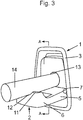
- the base member 1 comprises an cylindrical opening 13 for receiving an end part of a rod 14.
- the bow 6 has a ridge 11, which in turn has a recess 12 with a rounded shape. When in open position, the ridge is directed upwards and the recess in the ridge thus slightly downwards. The ridge gives the support member a hook function for clothes and the like.
- the recess 12 has a partly circular shape with an upper recess surface 12a which coincides with the direction of said cylindrical opening 13 in the base member 1, the tube opening having an inner wall 13a.
- the curved recess surface 12a and the cylindrical opening 13 can jointly take the load of an accessory load rod or rod element 14 (according to the above) which is placed accordingly.
- the rod 14 has a mainly circular circumference. If two fixing point assemblies are mounted, with the opening 13 and recess 12 directions in line, at a respective inside wall of a vehicle, they jointly can support and carry safely both ends of an accessory rod 14 or an accessory having two separate rod ends accordingly.
- Fig. 4 a section view according to the section A-A in Fig. 3 is shown.
- the rod 14 is resting in the recess 12 in the ridge 11 of the bow 6 and in the opening 13 of the base member 1.
- the pivot end 5 of the support member 2 has a protrusion part 15, which is positioned beyond the pivot axles 7, seen from the bow side, and is cooperating with a pivot stop surface 16 on the base member 1 in order to limit the pivotal movement of the support member relative to the base member, thus defining the open position of the support member.
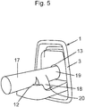
- Fig. 5 shows an example of an alternative, accessory rod 17, which has a radially protruding rod element 18 in the vicinity of a rod end 19.
- the protruding element 18 is adapted to the shape of the bow opening 20 in such a way that when the accessory rod is put in place, with the rod end in the opening 13 and the protruding element 18 positioned in the bow opening 20, the protruding element 18 is preventing the rod 17 from being turned around its axis or repositioned axially, i. e. the rod is locked in position.
- the base member opening 13 is dimensioned slightly wider than the circumference dimensions of the rod, especially at the entrance.
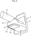
- Fig. 6 shows the same thing as Fig. 5 , but from a different angle. As can be seen, the protruding rod element 18 is reaching down through the bow opening 20 as the rod 17 rests in the recess 12.
- the shape of the opening 13 in the base member 1 must not be cylindrical but may have any suitable shape, e.g. square, polygonal or oval, preferably adapted to the rod shape or at least adapted to receive the rod.
- the recess preferably has a corresponding shape.
- the bow can also be designed in different shapes and the matching part accordingly.
- the protruding element 18 can be designed to be movable relative to the rod such that it can be positioned either in a retracted position out of the way, in order to be easily put in place, or in an expanded position for cooperation with the opening 20 of the support member 2.
- the inside of the bow ridge 12 can also be designed to cooperate with means on the rod to prevent axial displacement out of the base member opening.
- the base member opening can be hidden behind the support member element when it is in its stored position.
Landscapes
- Engineering & Computer Science (AREA)
- Mechanical Engineering (AREA)
- Transportation (AREA)
- Vehicle Step Arrangements And Article Storage (AREA)
Abstract
Description
- The present invention relates to a fixing point assembly, adapted to be mounted in a vehicle having an interior with an interior wall. The fixing point assembly comprises a base member and a support member, the support member being pivotably attached to the base member. The support member is movable between a stored, resting position at the base member and an open working position, projecting from the base member into the vehicle interior.
- The invention also relates to a vehicle accessory rod for attaching to a fixing point assembly according to the invention.
- Vehicles like cars, trucks and buses are often provided with hooks and the like for supporting goods like luggage and clothes. A problem is that the hooks usually are relatively small and ineffective for larger loads, since they are designed to be out of the way, when not used, and have minimal interference with the interior.
- In
US patent 5492260 , a garment support assembly is described that is foldable and thus can have a relatively useful size when needed and still be positioned out of the way when not used. The patent description discloses a retractable hook for garments comprising a base element and a U-shaped ring element which is pivotally connected to the base element. The disclosure further discloses construction details of the garment support element. - However, the above patent disclosure only shows a solution to the problem of hanging a number of garments in a vehicle. Besides the need of hanging garments in a vehicle there often is a need for fastening straps in order to tie down heavy loads e.g. on the luggage room floor. Also, often accessories like luggage nets are also used, and they need a good support for hooks or fastening rods or the like in order to be safe.
- The different needs presented above have up till now been solved by using supports of different kinds in the vehicles. This means that the spare parts are several and the car designers have to make choices.
- The present invention provides a versatile solution to all the above needs in one support only, providing support for a multiple of needs.
- The present invention concerns a fixing point assembly, adapted to be mounted in a vehicle having an interior and an interior wall. It comprises a base member and a support member, the support member being pivotally attached to the base member. The support member is movable between a stored, resting position with the base member and an open working position, projecting from the base member into the vehicle interior. The base member also comprises an opening for receiving an end part of a rod, which is used to support auxiliary equipment or luggage. In one embodiment the support member is adapted to support a rod placed with an end part in the base member opening, when the support member is in its open position.
- In a further embodiment the support member comprises a pivot end pivotally connected to the base member beneath the base member opening, as the fixing point assembly is mounted for use in a vehicle, a bow, the bow being connected to the pivot end.
- In another embodiment a the bow has a ridge, which is adapted to support a rod having entered the base member opening when the support member is in the open position.
- In still another embodiment the top of the bow ridge has a recess. The recess is adapted to cooperate with a rod having entered the base member opening when the support member is in the open position.
- Still further, in an embodiment, the base member opening has a wall, which has a cylindrical form. The recess is shaped to partly surround a cylindrically shaped rod, and the recess top surface is in line with the base member opening cylindrical wall when the support member is in the open position.
- The support member in some of the embodiments comprises a metal core and a plastic mould carried by the core.
- In yet an embodiment the bow has a bow opening on the inside.
- The invention also concerns a vehicle accessory rod having at least one rod end for attaching to a fixing point assembly according to the invention. The accessory rod comprises a radially protruding rod element at the rod end, the rod end being adapted to fit in the base member opening and the protruding rod element being adapted to fit in the support member bow opening of the fixing point assembly, whereby the protruding rod element and the bow opening cooperate to prevent pulling the rod end out of the base member opening and the turning of the rod relative to the support member, when the accessory rod end is entered into the base member opening.
- The objects and advantages of the present invention will be further clarified in the following description and appended claims and also shown on the accompanying drawings in which:
-
Fig. 1 is a view showing a fixing point assembly according to the invention with a support member in a stored position, -
Fig. 2 is a view of the fixing point assembly according toFig. 1 with the support member in a projecting position, being used both as a hook for a hanger and a fixing point for a strap down line, -
Fig. 3 is a view showing a fixing point assembly according to the invention used as a support for an accessory fastening rod, -
Fig. 4 is a view showing a section view A-A ofFig. 3 , -
Fig. 5 is a view showing a fixing point assembly according to the invention in combination with a vehicle accessory rod according to the invention and -
Fig. 6 is a view showing the combination according toFig. 5 from underneath, as mounted in a vehicle. - Referring to
Fig. 1 a fixing point assembly is shown, as mounted in a car in a known way on a car interior wall (not shown). The mounting place could be in a passenger compartment or in a booth or any other suitable place. The assembly comprises abase member 1 and asupport member 2. The assembly is shown with the base member in an upright position and thesupport member 1 in a stored position, more or less inside the base member. The base member has arim part 3, a bottom part (not entirely shown) and ahump part 4 on the bottom part. The support member has a lower part, apivot end 5, pivotally connected to the base member and having mainly the form of a symmetrical parallel trapezium, whichpivot end 5 carries a load support part, abow 6. Thebow 6 is connected to the supportmember pivot end 5 at both bow ends with anopening 20 inside the bow (shown inFig. 5 and6 ). When the support member is in the stored position, thebow 6 surrounds thehump part 4. The fixing point assembly thus makes a flush impression with the interior in the position shown inFig. 1 . - In
Fig. 2 the fixing point assembly is shown with thesupport member 2 in an open position, projecting from the interior wall into the interior of the car. At the support member pivot end 5 a first of twopivot axles 7 can be seen. Thefirst pivot axle 7 is entered into a corresponding axle hole (not shown) in the basemember rim part 3, as is a similar, second pivot axle (not shown) on the far side of the supportmember pivot end 5, thus making it possible for thesupport member 2 to pivot between the stored position, shown inFig.1 and the open position, shown inFig. 2 . - The
bow 6 on thesupport member 2 can in the open position serve as a hook for clothes, either directly, using the clothing loop, or indirectly, by using e.g. a hanger 8 (not part of the invention), as shown in theFig. 2 . Also, thebow 6 can serve as a fixing point for a hook 9 (not part of the invention), connected to a tie downline 10, as shown. In order to resist heavier loads, which can be the case when mounted in a luggage compartment or in the back of a station wagon, the fixing point assembly or at least thebow 6 can be made of metal. On the other hand, it can have a metal core and carry a plastic moulding. - According to the present invention, the
base member 1 comprises ancylindrical opening 13 for receiving an end part of arod 14. Further, as shown inFig. 2 and3 , thebow 6 has aridge 11, which in turn has arecess 12 with a rounded shape. When in open position, the ridge is directed upwards and the recess in the ridge thus slightly downwards. The ridge gives the support member a hook function for clothes and the like. Therecess 12 has a partly circular shape with anupper recess surface 12a which coincides with the direction of saidcylindrical opening 13 in thebase member 1, the tube opening having aninner wall 13a. In this way, thecurved recess surface 12a and thecylindrical opening 13 can jointly take the load of an accessory load rod or rod element 14 (according to the above) which is placed accordingly. Therod 14 has a mainly circular circumference. If two fixing point assemblies are mounted, with theopening 13 andrecess 12 directions in line, at a respective inside wall of a vehicle, they jointly can support and carry safely both ends of anaccessory rod 14 or an accessory having two separate rod ends accordingly. - In
Fig. 4 a section view according to the section A-A inFig. 3 is shown. As seen in the figure, therod 14 is resting in therecess 12 in theridge 11 of thebow 6 and in theopening 13 of thebase member 1. Thepivot end 5 of thesupport member 2 has aprotrusion part 15, which is positioned beyond thepivot axles 7, seen from the bow side, and is cooperating with apivot stop surface 16 on thebase member 1 in order to limit the pivotal movement of the support member relative to the base member, thus defining the open position of the support member. -
Fig. 5 shows an example of an alternative,accessory rod 17, which has a radially protrudingrod element 18 in the vicinity of arod end 19. The protrudingelement 18 is adapted to the shape of the bow opening 20 in such a way that when the accessory rod is put in place, with the rod end in theopening 13 and the protrudingelement 18 positioned in thebow opening 20, the protrudingelement 18 is preventing therod 17 from being turned around its axis or repositioned axially, i. e. the rod is locked in position. In order to neatly allow the rod to be placed in the locked position, the base member opening 13 is dimensioned slightly wider than the circumference dimensions of the rod, especially at the entrance. -
Fig. 6 shows the same thing asFig. 5 , but from a different angle. As can be seen, the protrudingrod element 18 is reaching down through the bow opening 20 as therod 17 rests in therecess 12. - It will be understood that a person skilled in the art may make modifications to the embodiments shown above and on the drawings within the scope of the claims. For example, the shape of the
opening 13 in thebase member 1 must not be cylindrical but may have any suitable shape, e.g. square, polygonal or oval, preferably adapted to the rod shape or at least adapted to receive the rod. In this case the recess preferably has a corresponding shape.
The bow can also be designed in different shapes and the matching part accordingly.
When in stored position, thesupport member 2 is preferably biased or retained by a spring means or a hooking means in a known way. The protrudingelement 18 can be designed to be movable relative to the rod such that it can be positioned either in a retracted position out of the way, in order to be easily put in place, or in an expanded position for cooperation with theopening 20 of thesupport member 2. The inside of thebow ridge 12 can also be designed to cooperate with means on the rod to prevent axial displacement out of the base member opening. The base member opening can be hidden behind the support member element when it is in its stored position.
Claims (9)
- A fixing point assembly, adapted to be mounted in a vehicle having an interior and an interior wall, the fixing point assembly comprising a base member (1) and a support member (2), the support member being pivotally attached to the base member (1) and movable between a stored, resting position with the base member (1) and an open working position, projecting from the base member (1) into the vehicle interior,
characterized in that the base member (1) comprises an opening (13) for receiving an end part of a rod (14,17). - A fixing point assembly according to claim 1, characterized in that the support member (2) is adapted to support a rod placed with an end part in the base member opening (13), when the support member (6) is in its open position.
- A fixing point assembly according to claim 2, characterized in that the support member (2) comprises a pivot end (5) pivotally connected to the base member (1) beneath the base member opening (13), as the fixing point assembly is mounted for use in a vehicle, a bow (6), the bow being connected to the pivot end (5).
- A fixing point assembly according to claim 3, characterized in that the bow (6) has a ridge (11), which is adapted to support a rod (14,17) having entered the base member opening (13) when the support member is in the open position.
- A fixing point assembly according to claim 4, characterized in that the top of the bow ridge (11) has a recess (12), the recess (12) being adapted to support a rod (14,17) having entered the base member opening (13) when the support member is in the open position.
- A fixing point assembly according to claim 5, characterized in that the base member opening (13) has a wall (13a), which has a cylindrical form and that the recess (12) is shaped to partly surround a cylindrically shaped rod (14,17), the recess top surface (21) being in line with the base member opening cylindrical wall (13a) when the support member (2) is in the open position.
- A fixing point assembly according to any of claims 1-6, characterized in that the support member (2) comprises a metal core and a plastic mould carried by the core.
- A fixing point assembly according to any of claims 1-7, characterized in that the bow (6) on the inside has a bow opening (20).
- A vehicle accessory rod for attaching to a fixing point assembly according to claim 8, the rod (17) having at least a rod end (19),
c h a r a c t e r i z e d i n that the accessory rod (17) comprises a radially protruding rod element (18) at the rod end (19), the rod end being adapted to fit in the base member opening (13) and the protruding rod element (18) being adapted to fit in the support member bow opening (20) of the fixing point assembly, whereby the protruding rod element (18) and the bow opening (20) cooperate to prevent pulling the rod end out of the base member opening (13) and the turning of the rod element relative to the support member, when the accessory rod end (19) is entered into the base member opening (13).
Priority Applications (2)
| Application Number | Priority Date | Filing Date | Title |
|---|---|---|---|
| EP20120151661 EP2617603B1 (en) | 2012-01-19 | 2012-01-19 | A fixing point assembly for vehicles |
| CN 201320028083 CN203157859U (en) | 2012-01-19 | 2013-01-18 | Fixed point assembly for vehicle |
Applications Claiming Priority (1)
| Application Number | Priority Date | Filing Date | Title |
|---|---|---|---|
| EP20120151661 EP2617603B1 (en) | 2012-01-19 | 2012-01-19 | A fixing point assembly for vehicles |
Publications (2)
| Publication Number | Publication Date |
|---|---|
| EP2617603A1 true EP2617603A1 (en) | 2013-07-24 |
| EP2617603B1 EP2617603B1 (en) | 2015-03-18 |
Family
ID=45507553
Family Applications (1)
| Application Number | Title | Priority Date | Filing Date |
|---|---|---|---|
| EP20120151661 Active EP2617603B1 (en) | 2012-01-19 | 2012-01-19 | A fixing point assembly for vehicles |
Country Status (2)
| Country | Link |
|---|---|
| EP (1) | EP2617603B1 (en) |
| CN (1) | CN203157859U (en) |
Cited By (3)
| Publication number | Priority date | Publication date | Assignee | Title |
|---|---|---|---|---|
| JP2014066267A (en) * | 2012-09-25 | 2014-04-17 | Nifco Inc | Hook device |
| US20140332575A1 (en) * | 2012-08-01 | 2014-11-13 | Ford Global Technologies, Llc | Vehicle garment hook assembly |
| EP4466162A1 (en) * | 2022-01-21 | 2024-11-27 | Volkswagen Aktiengesellschaft | Retaining apparatus and retaining element for a loading base of a vehicle |
Families Citing this family (1)
| Publication number | Priority date | Publication date | Assignee | Title |
|---|---|---|---|---|
| US9914399B2 (en) | 2015-11-10 | 2018-03-13 | Ford Global Technologies, Llc | Cargo management system and multifunction hook assembly |
Citations (6)
| Publication number | Priority date | Publication date | Assignee | Title |
|---|---|---|---|---|
| US5492260A (en) | 1994-08-19 | 1996-02-20 | General Motors Corporation | Garment support assembly |
| US20020113465A1 (en) * | 2001-02-22 | 2002-08-22 | Takahiko Inari | Assist grip |
| EP1398220A1 (en) * | 2002-09-10 | 2004-03-17 | Adam Opel Ag | Vehicle provided with accessory holding devices |
| FR2897029A3 (en) * | 2006-02-07 | 2007-08-10 | Renault Sas | Bag hooking device for use in e.g. fascia of motor vehicle, e.g. citroen C4, has hook movable between retracted position in housing and deployed position outside housing, where hook is movable in rotation along vertical axis |
| US20090250579A1 (en) * | 2008-04-08 | 2009-10-08 | Nifco Inc. | Apparatus with a rotating body |
| EP2343216A1 (en) * | 2008-09-30 | 2011-07-13 | Nifco INC. | Operation mechanism for movable body |
-
2012
- 2012-01-19 EP EP20120151661 patent/EP2617603B1/en active Active
-
2013
- 2013-01-18 CN CN 201320028083 patent/CN203157859U/en not_active Expired - Lifetime
Patent Citations (6)
| Publication number | Priority date | Publication date | Assignee | Title |
|---|---|---|---|---|
| US5492260A (en) | 1994-08-19 | 1996-02-20 | General Motors Corporation | Garment support assembly |
| US20020113465A1 (en) * | 2001-02-22 | 2002-08-22 | Takahiko Inari | Assist grip |
| EP1398220A1 (en) * | 2002-09-10 | 2004-03-17 | Adam Opel Ag | Vehicle provided with accessory holding devices |
| FR2897029A3 (en) * | 2006-02-07 | 2007-08-10 | Renault Sas | Bag hooking device for use in e.g. fascia of motor vehicle, e.g. citroen C4, has hook movable between retracted position in housing and deployed position outside housing, where hook is movable in rotation along vertical axis |
| US20090250579A1 (en) * | 2008-04-08 | 2009-10-08 | Nifco Inc. | Apparatus with a rotating body |
| EP2343216A1 (en) * | 2008-09-30 | 2011-07-13 | Nifco INC. | Operation mechanism for movable body |
Cited By (3)
| Publication number | Priority date | Publication date | Assignee | Title |
|---|---|---|---|---|
| US20140332575A1 (en) * | 2012-08-01 | 2014-11-13 | Ford Global Technologies, Llc | Vehicle garment hook assembly |
| JP2014066267A (en) * | 2012-09-25 | 2014-04-17 | Nifco Inc | Hook device |
| EP4466162A1 (en) * | 2022-01-21 | 2024-11-27 | Volkswagen Aktiengesellschaft | Retaining apparatus and retaining element for a loading base of a vehicle |
Also Published As
| Publication number | Publication date |
|---|---|
| CN203157859U (en) | 2013-08-28 |
| EP2617603B1 (en) | 2015-03-18 |
Similar Documents
| Publication | Publication Date | Title |
|---|---|---|
| US8556324B1 (en) | Utility vehicle | |
| AU2018223213B2 (en) | Roof rack | |
| US7837248B2 (en) | Trim system for an automotive vehicle | |
| US5288122A (en) | Load restraining device | |
| EP2617603B1 (en) | A fixing point assembly for vehicles | |
| US6183177B1 (en) | Device for securing cargo | |
| US20080174145A1 (en) | Retractable assist handle for a vehicle | |
| US8480149B2 (en) | Hitch attached extension for over sized cargo | |
| US9783117B2 (en) | Luggage compartment hook organizer | |
| CN211869266U (en) | Transportation means | |
| JPH10147183A (en) | Load carrier | |
| CN105291997A (en) | Laterally moving cargo shade and net | |
| CA2839639A1 (en) | A multi-functional box stop device for the trunk of a car | |
| US5419672A (en) | Tail gate hanger | |
| CN107226032A (en) | Inside and outside cargo management system comprising grid | |
| JP5107297B2 (en) | Car accessories | |
| US1974599A (en) | Tire carrier for extension trunks | |
| CN215284613U (en) | Vehicle-mounted multifunctional luggage rack | |
| CN109383644B (en) | Tire carrier | |
| US10246145B1 (en) | Tire carrier | |
| CN212195306U (en) | Automobile top storage rack | |
| CN203681357U (en) | Vehicle-mounted trash can | |
| CN112977317B (en) | Vehicle and rear lower part protection device thereof | |
| JP3235153U (en) | Seat storage case for loading platform | |
| CN212685423U (en) | Vehicle-mounted hook |
Legal Events
| Date | Code | Title | Description |
|---|---|---|---|
| PUAI | Public reference made under article 153(3) epc to a published international application that has entered the european phase |
Free format text: ORIGINAL CODE: 0009012 |
|
| AK | Designated contracting states |
Kind code of ref document: A1 Designated state(s): AL AT BE BG CH CY CZ DE DK EE ES FI FR GB GR HR HU IE IS IT LI LT LU LV MC MK MT NL NO PL PT RO RS SE SI SK SM TR |
|
| AX | Request for extension of the european patent |
Extension state: BA ME |
|
| 17P | Request for examination filed |
Effective date: 20140124 |
|
| RBV | Designated contracting states (corrected) |
Designated state(s): AL AT BE BG CH CY CZ DE DK EE ES FI FR GB GR HR HU IE IS IT LI LT LU LV MC MK MT NL NO PL PT RO RS SE SI SK SM TR |
|
| GRAP | Despatch of communication of intention to grant a patent |
Free format text: ORIGINAL CODE: EPIDOSNIGR1 |
|
| INTG | Intention to grant announced |
Effective date: 20140915 |
|
| GRAS | Grant fee paid |
Free format text: ORIGINAL CODE: EPIDOSNIGR3 |
|
| GRAA | (expected) grant |
Free format text: ORIGINAL CODE: 0009210 |
|
| AK | Designated contracting states |
Kind code of ref document: B1 Designated state(s): AL AT BE BG CH CY CZ DE DK EE ES FI FR GB GR HR HU IE IS IT LI LT LU LV MC MK MT NL NO PL PT RO RS SE SI SK SM TR |
|
| REG | Reference to a national code |
Ref country code: GB Ref legal event code: FG4D |
|
| REG | Reference to a national code |
Ref country code: CH Ref legal event code: EP |
|
| REG | Reference to a national code |
Ref country code: IE Ref legal event code: FG4D |
|
| REG | Reference to a national code |
Ref country code: AT Ref legal event code: REF Ref document number: 716339 Country of ref document: AT Kind code of ref document: T Effective date: 20150415 |
|
| REG | Reference to a national code |
Ref country code: DE Ref legal event code: R096 Ref document number: 602012005903 Country of ref document: DE Effective date: 20150430 |
|
| REG | Reference to a national code |
Ref country code: SE Ref legal event code: TRGR |
|
| REG | Reference to a national code |
Ref country code: NL Ref legal event code: VDEP Effective date: 20150318 |
|
| REG | Reference to a national code |
Ref country code: NL Ref legal event code: VDEP Effective date: 20150318 |
|
| PG25 | Lapsed in a contracting state [announced via postgrant information from national office to epo] |
Ref country code: LT Free format text: LAPSE BECAUSE OF FAILURE TO SUBMIT A TRANSLATION OF THE DESCRIPTION OR TO PAY THE FEE WITHIN THE PRESCRIBED TIME-LIMIT Effective date: 20150318 Ref country code: NO Free format text: LAPSE BECAUSE OF FAILURE TO SUBMIT A TRANSLATION OF THE DESCRIPTION OR TO PAY THE FEE WITHIN THE PRESCRIBED TIME-LIMIT Effective date: 20150618 Ref country code: FI Free format text: LAPSE BECAUSE OF FAILURE TO SUBMIT A TRANSLATION OF THE DESCRIPTION OR TO PAY THE FEE WITHIN THE PRESCRIBED TIME-LIMIT Effective date: 20150318 Ref country code: HR Free format text: LAPSE BECAUSE OF FAILURE TO SUBMIT A TRANSLATION OF THE DESCRIPTION OR TO PAY THE FEE WITHIN THE PRESCRIBED TIME-LIMIT Effective date: 20150318 |
|
| REG | Reference to a national code |
Ref country code: AT Ref legal event code: MK05 Ref document number: 716339 Country of ref document: AT Kind code of ref document: T Effective date: 20150318 |
|
| REG | Reference to a national code |
Ref country code: LT Ref legal event code: MG4D |
|
| PG25 | Lapsed in a contracting state [announced via postgrant information from national office to epo] |
Ref country code: RS Free format text: LAPSE BECAUSE OF FAILURE TO SUBMIT A TRANSLATION OF THE DESCRIPTION OR TO PAY THE FEE WITHIN THE PRESCRIBED TIME-LIMIT Effective date: 20150318 Ref country code: GR Free format text: LAPSE BECAUSE OF FAILURE TO SUBMIT A TRANSLATION OF THE DESCRIPTION OR TO PAY THE FEE WITHIN THE PRESCRIBED TIME-LIMIT Effective date: 20150619 Ref country code: LV Free format text: LAPSE BECAUSE OF FAILURE TO SUBMIT A TRANSLATION OF THE DESCRIPTION OR TO PAY THE FEE WITHIN THE PRESCRIBED TIME-LIMIT Effective date: 20150318 |
|
| PG25 | Lapsed in a contracting state [announced via postgrant information from national office to epo] |
Ref country code: NL Free format text: LAPSE BECAUSE OF FAILURE TO SUBMIT A TRANSLATION OF THE DESCRIPTION OR TO PAY THE FEE WITHIN THE PRESCRIBED TIME-LIMIT Effective date: 20150318 |
|
| PG25 | Lapsed in a contracting state [announced via postgrant information from national office to epo] |
Ref country code: RO Free format text: LAPSE BECAUSE OF FAILURE TO SUBMIT A TRANSLATION OF THE DESCRIPTION OR TO PAY THE FEE WITHIN THE PRESCRIBED TIME-LIMIT Effective date: 20150318 Ref country code: EE Free format text: LAPSE BECAUSE OF FAILURE TO SUBMIT A TRANSLATION OF THE DESCRIPTION OR TO PAY THE FEE WITHIN THE PRESCRIBED TIME-LIMIT Effective date: 20150318 Ref country code: SK Free format text: LAPSE BECAUSE OF FAILURE TO SUBMIT A TRANSLATION OF THE DESCRIPTION OR TO PAY THE FEE WITHIN THE PRESCRIBED TIME-LIMIT Effective date: 20150318 Ref country code: PT Free format text: LAPSE BECAUSE OF FAILURE TO SUBMIT A TRANSLATION OF THE DESCRIPTION OR TO PAY THE FEE WITHIN THE PRESCRIBED TIME-LIMIT Effective date: 20150720 Ref country code: ES Free format text: LAPSE BECAUSE OF FAILURE TO SUBMIT A TRANSLATION OF THE DESCRIPTION OR TO PAY THE FEE WITHIN THE PRESCRIBED TIME-LIMIT Effective date: 20150318 Ref country code: CZ Free format text: LAPSE BECAUSE OF FAILURE TO SUBMIT A TRANSLATION OF THE DESCRIPTION OR TO PAY THE FEE WITHIN THE PRESCRIBED TIME-LIMIT Effective date: 20150318 |
|
| PG25 | Lapsed in a contracting state [announced via postgrant information from national office to epo] |
Ref country code: PL Free format text: LAPSE BECAUSE OF FAILURE TO SUBMIT A TRANSLATION OF THE DESCRIPTION OR TO PAY THE FEE WITHIN THE PRESCRIBED TIME-LIMIT Effective date: 20150318 Ref country code: IS Free format text: LAPSE BECAUSE OF FAILURE TO SUBMIT A TRANSLATION OF THE DESCRIPTION OR TO PAY THE FEE WITHIN THE PRESCRIBED TIME-LIMIT Effective date: 20150718 Ref country code: AT Free format text: LAPSE BECAUSE OF FAILURE TO SUBMIT A TRANSLATION OF THE DESCRIPTION OR TO PAY THE FEE WITHIN THE PRESCRIBED TIME-LIMIT Effective date: 20150318 |
|
| REG | Reference to a national code |
Ref country code: DE Ref legal event code: R097 Ref document number: 602012005903 Country of ref document: DE |
|
| PG25 | Lapsed in a contracting state [announced via postgrant information from national office to epo] |
Ref country code: IT Free format text: LAPSE BECAUSE OF FAILURE TO SUBMIT A TRANSLATION OF THE DESCRIPTION OR TO PAY THE FEE WITHIN THE PRESCRIBED TIME-LIMIT Effective date: 20150318 |
|
| PLBE | No opposition filed within time limit |
Free format text: ORIGINAL CODE: 0009261 |
|
| STAA | Information on the status of an ep patent application or granted ep patent |
Free format text: STATUS: NO OPPOSITION FILED WITHIN TIME LIMIT |
|
| PG25 | Lapsed in a contracting state [announced via postgrant information from national office to epo] |
Ref country code: DK Free format text: LAPSE BECAUSE OF FAILURE TO SUBMIT A TRANSLATION OF THE DESCRIPTION OR TO PAY THE FEE WITHIN THE PRESCRIBED TIME-LIMIT Effective date: 20150318 |
|
| 26N | No opposition filed |
Effective date: 20151221 |
|
| PG25 | Lapsed in a contracting state [announced via postgrant information from national office to epo] |
Ref country code: SI Free format text: LAPSE BECAUSE OF FAILURE TO SUBMIT A TRANSLATION OF THE DESCRIPTION OR TO PAY THE FEE WITHIN THE PRESCRIBED TIME-LIMIT Effective date: 20150318 |
|
| PG25 | Lapsed in a contracting state [announced via postgrant information from national office to epo] |
Ref country code: BE Free format text: LAPSE BECAUSE OF NON-PAYMENT OF DUE FEES Effective date: 20160131 |
|
| PG25 | Lapsed in a contracting state [announced via postgrant information from national office to epo] |
Ref country code: BE Free format text: LAPSE BECAUSE OF FAILURE TO SUBMIT A TRANSLATION OF THE DESCRIPTION OR TO PAY THE FEE WITHIN THE PRESCRIBED TIME-LIMIT Effective date: 20150318 Ref country code: LU Free format text: LAPSE BECAUSE OF FAILURE TO SUBMIT A TRANSLATION OF THE DESCRIPTION OR TO PAY THE FEE WITHIN THE PRESCRIBED TIME-LIMIT Effective date: 20160119 |
|
| REG | Reference to a national code |
Ref country code: CH Ref legal event code: PL |
|
| PG25 | Lapsed in a contracting state [announced via postgrant information from national office to epo] |
Ref country code: MC Free format text: LAPSE BECAUSE OF FAILURE TO SUBMIT A TRANSLATION OF THE DESCRIPTION OR TO PAY THE FEE WITHIN THE PRESCRIBED TIME-LIMIT Effective date: 20150318 |
|
| REG | Reference to a national code |
Ref country code: FR Ref legal event code: ST Effective date: 20160930 |
|
| PG25 | Lapsed in a contracting state [announced via postgrant information from national office to epo] |
Ref country code: CH Free format text: LAPSE BECAUSE OF NON-PAYMENT OF DUE FEES Effective date: 20160131 Ref country code: LI Free format text: LAPSE BECAUSE OF NON-PAYMENT OF DUE FEES Effective date: 20160131 |
|
| REG | Reference to a national code |
Ref country code: IE Ref legal event code: MM4A |
|
| PG25 | Lapsed in a contracting state [announced via postgrant information from national office to epo] |
Ref country code: FR Free format text: LAPSE BECAUSE OF NON-PAYMENT OF DUE FEES Effective date: 20160201 |
|
| PG25 | Lapsed in a contracting state [announced via postgrant information from national office to epo] |
Ref country code: IE Free format text: LAPSE BECAUSE OF NON-PAYMENT OF DUE FEES Effective date: 20160119 |
|
| PG25 | Lapsed in a contracting state [announced via postgrant information from national office to epo] |
Ref country code: MT Free format text: LAPSE BECAUSE OF FAILURE TO SUBMIT A TRANSLATION OF THE DESCRIPTION OR TO PAY THE FEE WITHIN THE PRESCRIBED TIME-LIMIT Effective date: 20150318 |
|
| PG25 | Lapsed in a contracting state [announced via postgrant information from national office to epo] |
Ref country code: SM Free format text: LAPSE BECAUSE OF FAILURE TO SUBMIT A TRANSLATION OF THE DESCRIPTION OR TO PAY THE FEE WITHIN THE PRESCRIBED TIME-LIMIT Effective date: 20150318 Ref country code: CY Free format text: LAPSE BECAUSE OF FAILURE TO SUBMIT A TRANSLATION OF THE DESCRIPTION OR TO PAY THE FEE WITHIN THE PRESCRIBED TIME-LIMIT Effective date: 20150318 Ref country code: HU Free format text: LAPSE BECAUSE OF FAILURE TO SUBMIT A TRANSLATION OF THE DESCRIPTION OR TO PAY THE FEE WITHIN THE PRESCRIBED TIME-LIMIT; INVALID AB INITIO Effective date: 20120119 |
|
| PG25 | Lapsed in a contracting state [announced via postgrant information from national office to epo] |
Ref country code: TR Free format text: LAPSE BECAUSE OF FAILURE TO SUBMIT A TRANSLATION OF THE DESCRIPTION OR TO PAY THE FEE WITHIN THE PRESCRIBED TIME-LIMIT Effective date: 20150318 Ref country code: MK Free format text: LAPSE BECAUSE OF FAILURE TO SUBMIT A TRANSLATION OF THE DESCRIPTION OR TO PAY THE FEE WITHIN THE PRESCRIBED TIME-LIMIT Effective date: 20150318 Ref country code: MT Free format text: LAPSE BECAUSE OF FAILURE TO SUBMIT A TRANSLATION OF THE DESCRIPTION OR TO PAY THE FEE WITHIN THE PRESCRIBED TIME-LIMIT Effective date: 20160131 |
|
| PG25 | Lapsed in a contracting state [announced via postgrant information from national office to epo] |
Ref country code: BG Free format text: LAPSE BECAUSE OF FAILURE TO SUBMIT A TRANSLATION OF THE DESCRIPTION OR TO PAY THE FEE WITHIN THE PRESCRIBED TIME-LIMIT Effective date: 20150318 |
|
| PG25 | Lapsed in a contracting state [announced via postgrant information from national office to epo] |
Ref country code: AL Free format text: LAPSE BECAUSE OF FAILURE TO SUBMIT A TRANSLATION OF THE DESCRIPTION OR TO PAY THE FEE WITHIN THE PRESCRIBED TIME-LIMIT Effective date: 20150318 |
|
| PGFP | Annual fee paid to national office [announced via postgrant information from national office to epo] |
Ref country code: GB Payment date: 20190123 Year of fee payment: 8 |
|
| PGFP | Annual fee paid to national office [announced via postgrant information from national office to epo] |
Ref country code: SE Payment date: 20190115 Year of fee payment: 8 |
|
| REG | Reference to a national code |
Ref country code: SE Ref legal event code: EUG |
|
| GBPC | Gb: european patent ceased through non-payment of renewal fee |
Effective date: 20200119 |
|
| REG | Reference to a national code |
Ref country code: SE Ref legal event code: EUG |
|
| PG25 | Lapsed in a contracting state [announced via postgrant information from national office to epo] |
Ref country code: GB Free format text: LAPSE BECAUSE OF NON-PAYMENT OF DUE FEES Effective date: 20200119 Ref country code: SE Free format text: LAPSE BECAUSE OF NON-PAYMENT OF DUE FEES Effective date: 20200120 |
|
| P01 | Opt-out of the competence of the unified patent court (upc) registered |
Effective date: 20231212 |
|
| PGFP | Annual fee paid to national office [announced via postgrant information from national office to epo] |
Ref country code: DE Payment date: 20241218 Year of fee payment: 14 |