EP2617458A1 - Implantable neural interface device with a connector having a slitted deformable section - Google Patents
Implantable neural interface device with a connector having a slitted deformable section Download PDFInfo
- Publication number
- EP2617458A1 EP2617458A1 EP13151575.1A EP13151575A EP2617458A1 EP 2617458 A1 EP2617458 A1 EP 2617458A1 EP 13151575 A EP13151575 A EP 13151575A EP 2617458 A1 EP2617458 A1 EP 2617458A1
- Authority
- EP
- European Patent Office
- Prior art keywords
- connector
- interface device
- neural interface
- carrier
- sidewall
- Prior art date
- Legal status (The legal status is an assumption and is not a legal conclusion. Google has not performed a legal analysis and makes no representation as to the accuracy of the status listed.)
- Granted
Links
Images





Classifications
-
- A—HUMAN NECESSITIES
- A61—MEDICAL OR VETERINARY SCIENCE; HYGIENE
- A61B—DIAGNOSIS; SURGERY; IDENTIFICATION
- A61B5/00—Measuring for diagnostic purposes; Identification of persons
- A61B5/24—Detecting, measuring or recording bioelectric or biomagnetic signals of the body or parts thereof
- A61B5/25—Bioelectric electrodes therefor
- A61B5/279—Bioelectric electrodes therefor specially adapted for particular uses
- A61B5/291—Bioelectric electrodes therefor specially adapted for particular uses for electroencephalography [EEG]
- A61B5/293—Invasive
-
- A—HUMAN NECESSITIES
- A61—MEDICAL OR VETERINARY SCIENCE; HYGIENE
- A61B—DIAGNOSIS; SURGERY; IDENTIFICATION
- A61B5/00—Measuring for diagnostic purposes; Identification of persons
- A61B5/68—Arrangements of detecting, measuring or recording means, e.g. sensors, in relation to patient
- A61B5/6846—Arrangements of detecting, measuring or recording means, e.g. sensors, in relation to patient specially adapted to be brought in contact with an internal body part, i.e. invasive
- A61B5/6867—Arrangements of detecting, measuring or recording means, e.g. sensors, in relation to patient specially adapted to be brought in contact with an internal body part, i.e. invasive specially adapted to be attached or implanted in a specific body part
- A61B5/6868—Brain
-
- A—HUMAN NECESSITIES
- A61—MEDICAL OR VETERINARY SCIENCE; HYGIENE
- A61N—ELECTROTHERAPY; MAGNETOTHERAPY; RADIATION THERAPY; ULTRASOUND THERAPY
- A61N1/00—Electrotherapy; Circuits therefor
- A61N1/02—Details
- A61N1/04—Electrodes
- A61N1/05—Electrodes for implantation or insertion into the body, e.g. heart electrode
-
- A—HUMAN NECESSITIES
- A61—MEDICAL OR VETERINARY SCIENCE; HYGIENE
- A61N—ELECTROTHERAPY; MAGNETOTHERAPY; RADIATION THERAPY; ULTRASOUND THERAPY
- A61N1/00—Electrotherapy; Circuits therefor
- A61N1/02—Details
- A61N1/04—Electrodes
- A61N1/05—Electrodes for implantation or insertion into the body, e.g. heart electrode
- A61N1/0526—Head electrodes
- A61N1/0529—Electrodes for brain stimulation
-
- A—HUMAN NECESSITIES
- A61—MEDICAL OR VETERINARY SCIENCE; HYGIENE
- A61N—ELECTROTHERAPY; MAGNETOTHERAPY; RADIATION THERAPY; ULTRASOUND THERAPY
- A61N1/00—Electrotherapy; Circuits therefor
- A61N1/02—Details
- A61N1/04—Electrodes
- A61N1/05—Electrodes for implantation or insertion into the body, e.g. heart electrode
- A61N1/0551—Spinal or peripheral nerve electrodes
-
- A—HUMAN NECESSITIES
- A61—MEDICAL OR VETERINARY SCIENCE; HYGIENE
- A61B—DIAGNOSIS; SURGERY; IDENTIFICATION
- A61B2562/00—Details of sensors; Constructional details of sensor housings or probes; Accessories for sensors
- A61B2562/18—Shielding or protection of sensors from environmental influences, e.g. protection from mechanical damage
- A61B2562/187—Strain relief means
-
- A—HUMAN NECESSITIES
- A61—MEDICAL OR VETERINARY SCIENCE; HYGIENE
- A61B—DIAGNOSIS; SURGERY; IDENTIFICATION
- A61B5/00—Measuring for diagnostic purposes; Identification of persons
- A61B5/68—Arrangements of detecting, measuring or recording means, e.g. sensors, in relation to patient
- A61B5/6846—Arrangements of detecting, measuring or recording means, e.g. sensors, in relation to patient specially adapted to be brought in contact with an internal body part, i.e. invasive
- A61B5/6847—Arrangements of detecting, measuring or recording means, e.g. sensors, in relation to patient specially adapted to be brought in contact with an internal body part, i.e. invasive mounted on an invasive device
- A61B5/686—Permanently implanted devices, e.g. pacemakers, other stimulators, biochips
-
- A—HUMAN NECESSITIES
- A61—MEDICAL OR VETERINARY SCIENCE; HYGIENE
- A61N—ELECTROTHERAPY; MAGNETOTHERAPY; RADIATION THERAPY; ULTRASOUND THERAPY
- A61N1/00—Electrotherapy; Circuits therefor
- A61N1/02—Details
- A61N1/04—Electrodes
- A61N1/05—Electrodes for implantation or insertion into the body, e.g. heart electrode
- A61N1/0526—Head electrodes
- A61N1/0529—Electrodes for brain stimulation
- A61N1/0539—Anchoring of brain electrode systems, e.g. within burr hole
Definitions
- This invention relates generally to the implantable medical devices and, more specifically, to an improved implantable neural interface device with a deformable carrier or connector.
- Conventional carriers or connectors for neural interface devices have a tendency to "drift" after implantation in targeted tissue. This is due, in part, to the mechanical mismatch between the relatively stiff carrier for the neural interface device and the target body tissue and, in part, to tissue regrowth around the neural interface device. Any relative movement between the neural interface device and body tissue can result in the electrode array moving away from the targeted tissue.
- the present invention provides such an improved deformable carrier or connector for an implantable neural interface device.
- FIGs. 1 and 1A to 1C illustrate a preferred embodiment of an implantable neural interface device 10 according to the present invention.
- the neural interface device 10 is implantable into a wide variety of body tissue including the brain, spinal cord, peripheral nerve, muscle, and/or any suitable neural tissue and comprises a carrier 12 supporting at least one electrode array 14.
- the electrode array 14 may be made from a thin-film polymer substrate such that there is a high density of electrode sites at a first end of the array (e.g., the distal end) and bonding regions at a second end of the array (e.g., the proximal end).
- the polymer substrate is preferably parylene, polyimide, silicone or a suitable combination of organic and inorganic dielectrics, but may additionally and/or alternatively be made of any suitable material.
- the substrate can also include a dielectric layer comprised of silicon nitride, silicon dioxide, silicon carbide, and mixtures thereof.
- the carrier 12 is preferably of silicone or polyurethane and comprises a tubular sidewall 16 having a length extending from a proximal carrier portion 12A to a distal carrier portion 12B.
- the distal carrier portion 12B has a step 12C transition to a thin-walled distal end 12D.
- the step 12C has a height that substantially matches the thickness of the thin film substrate comprising the electrode array 14. That way, the electrode assay 14 is wrapped and otherwise supported at least part way around the circumference of the distal carrier end 12D to provide a smooth transition to the distal carrier portion 12B.
- small non-homogenous perforations may be micromachined into the thin-film substrate to allow for the material of the carrier 12 to form a robust anchor with the electrode array 14.
- At least one deformable segment 18 is provided along the length of the carrier 12 intermediate a first carrier sidewall portion 16A and a second carrier sidewall portion 16B.
- the deformable segment 18 is a portion or location along the carrier 12 that is compressible, tensile, articulatable, and/or rotatable along an axis thereof, such as a longitudinal axis of the carrier. Compression or extension of the deformable segment 18 results in translation of the carrier sidewall portions 16A, 16B relative to one another along an axis of insertion (e.g., longitudinal axis along the carrier).
- the deformable segment 18 may additionally and/or alternatively bend or rotate or deform in any other suitable manner along any suitable axis.
- the deformable segment 18 may bend or curve to enable the sidewall portions 16A, 16B to become axially misaligned or curved along the length of the carrier 12.
- the entire length of the carrier 12 is substantially equivalent to a deformable segment 18 such that the carrier is adapted to deform in compression, extension, and/or any other suitable manner.
- An electrical conductor 20 extends from the proximal carrier portion 12A to the distal carrier portion 12B where the conductor electrically connects to at least one electrode site 22 of the electrode array 14 supported by the distal carrier end 12D.
- the electrode site 22 is exemplary of a stimulation electrode configured for electrical stimulation of body tissue or a recording electrode for recording of physiological data from body tissue.
- the novel carrier 12 facilitates insertion or implantation of the electrode array 14 into body tissue and, once implanted, helps mitigate or eliminate drift (movement) of the implanted electrode array 14 within the tissue.
- the conductor 20 preferably has coiled or otherwise stretchable or deformable sections 20A that coincide with the deformable segments 18 in the carrier 12 of the neural interface device 10.
- the conductor 20 is preferably a thin-film structure containing multiple individually conductive traces, but may be a wire or any suitable conductive material.
- the conductor 20 may be wound around the external surface of the carrier 12, wound within a wall of the carrier, or wound around an internal surface of the carrier.
- the coiling or winding density is preferably selectively varied along the length of the carrier 12 to modulate the flexibility of the conductor 20.
- the conductor 20 include at least one section of lower coiling density corresponding to or aligned with a deformable segment 18 and at least one section of higher coiling density corresponding to or aligned with one of the carrier sidewall section 16A, 16B.
- the carrier 12 and coiled conductor 20 may be deformable in tandem in compression, tension or extension, articulation, rotation and/or any suitable manner.
- FIG. 2 is a schematic illustration of the neural interface device 10 according to the present invention extending through the cranium 24 and into brain tissue.
- This drawing shows that brain tissue is not necessarily homogenous.
- the brain tissue is depicted as comprising tissue layers or regions 26A, 26B and 26C.
- the neural interface device 10 has been implanted into the brain tissue with the electrode array 14 residing at a target tissue site 28.
- FIG. 3 shows that relative shifting has occurred between the various tissue layers or regions 26A, 26B and 26C. This shifting results in the electrode array 14A of a prior art neural interface device 10A no longer residing at the target tissue site 28. The consequence can be diminished or even completely ineffective neural stimulation, which is undesirable.
- the carrier 12 of the present neural interface device 10 is preferably at least partially made of a flexible material, such as an elastomer. Nitinol is another preferred material for the carrier 12.
- the carrier 12 is preferably tubular with a substantially cylindrical inner surface and includes one or more lumens 30 ( FIG. 1A ), such as for receiving a stylet 32 ( FIG. 1C ) therein.
- the stylet 32 has a pointed tip at its distal end 32A that helps facilitate insertion of the neural interface device 10 into tissue.
- the stylet 32 can have a lumen 34 for transporting fluids or serving as a passage for moving other devices (not shown) through the stylet/carrier assembly from the proximal carrier portion 12A to the distal carrier portion 12B and out the stylet end 32A thereof.
- the stylet 32 may be adapted to remain in the tissue coupled to the carrier 12 and include deformable segments 36 similar to those 18 of the carrier 12 that enable compression and/or extension. If provided, the deformable segments 36 of the stylet 32 are preferably aligned with those of the carrier 12. That is so compression and extension of the stylet 32 and carrier 12 correspond to each other. Alternatively, the stylet 32 may be adapted for removal from the carrier 12 after implantation of the neural interface device 10 into body tissue.
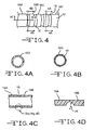
- FIGs. 4 and 4A to 4C illustrate a first embodiment of a carrier 12 according to the present invention.
- the carrier 12 comprises the tubular sidewall 16 with a substantially cylindrical inner surface having one or more deformable segments 18 provided at spaced locations along its length.
- the tubular sidewall 16 comprises a plurality of relatively less deformable carrier sidewall portions 16A, 16B, 16C, 16D and 16E, etc. spaced apart from each other by deformable segments 18.
- the less deformable sidewall portions 16A to 16E each have a first wall thickness that is substantially uniform around the annular extent thereof. This is illustrated in the cross-sections of FIGs. 4A and 4C .
- the deformable segments 18 are provided by an annular thinning of the wall thickness.
- the exemplary deformable segment 18 shown in FIGs. 4C has a radiused curvature 38 from where it connects to proximal sidewall segment 16A and to distal sidewall segment 16B.
- the radiused curvature of the deformable segment has a cross-section along a plane aligned perpendicular to a longitudinal axis of the carrier 16 that meets the proximal carrier portion 16A of the first wall thickness and curves to a trough having a second wall thickness at about a midpoint to a distal carrier portion 16B of the first wall thickness.
- the carrier segments 16A to 16E, etc. generally have a first wall thickness and the deformable segments 18 generally have a second wall thickness that is less than the first wall thickness.
- the carrier 12 is of a continuous molded tubular construction with the thinned deformable segments 18 characterized as a mechanically thinning of the sidewall 16. Thinning of the sidewall can be done by any one of a number of methods including turning the carrier 12 on a lathe, by selective heat pressing the sidewall 16, and the like. Moreover, the carrier sidewall segments 16A to 16E and the deformable segments 18 can be separately manufactured and then serially connected together by thermal sealing, epoxy, or any suitable sealing or coupling method.
- the deformable segments 18 enable the carrier 12 and the supported electrode array 14 to remain in the correct position and orientation with respect to the targeted tissue 28.
- the deformable segments 18 are more pliable than the remainder of the carrier sidewall 16 to preferably move in response to forces imparted on the carrier 12 and the electrode array 14 by the tissue.
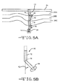
- the deformable segments 18 enable the carrier 12 to move in compression and extension 40.
- FIG. 5B shows that the deformable segment 18 enables the carrier 12 to undergo both bending 42 and rotational 44 movement.
- the term pliable in reference to the deformable segments 18 means easily bent, relatively more flexible, or relatively suppler.
- FIG. 6 illustrates that a deformable segment 46 does not necessarily require the radiused curvature 38 shown for deformable segment 18 in FIGs. 4C and 4D .
- the deformable segment 46 can have an irregular or graduated cross-sectional shape that is thinnest at a proximal end 46A and gradually thickens as the segment extends to a distal segment end 46B connected to the next carrier sidewall segment 16B.
- the irregularly-shaped deformable segment 46 can be reversed to that shown in FIG. 6 . That would be where the segment 46 is thickest at the proximal carrier sidewall segment 16A and thins as it extends to the next, more distal carrier sidewall segment 16B.
- the deformable segments 18 are made of a more flexible material or overall composite of materials having a lower elastic modulus than the carrier segments 16A to 16E, etc.
- the carrier sidewall segments are of a polymeric material having a durometer ranging from about 75A to about 60A, more preferably of a polymeric material having a durometer ranging from about 70A to about 55A.
- the deformable segments 18, 46 are of a more flexible polymeric material having a durometer ranging from about 50A to about 25A, more preferably from about 45A to about 30A.
- the carrier sidewall 16 is of a first polymeric material having a durometer ranging from about 75A to about 60A and the deformable segment 18 is of a second polymeric material having a durometer ranging from about 50A to 25A. Moreover, the carrier sidewall 16 of the first polymeric material and the deformable segment 18 of the second polymeric material have similar thicknesses.
- the carrier may include one or more anchoring features, such as an etched recess 48 or a through-hole 50 in the carrier sidewall 16.
- the anchoring features 48, 50 may help promote tissue regrowth into the carrier structure, thereby improving anchoring of the carrier and/or first electrical subsystem in tissue.
- the carrier sidewall 16 may also be selectively coated with adhesion promoting factors, such as laminin, fibronectin, L1 molecule ( Azemi, Cui 2011, Biomaterials ), etc., to promote tissue adhesion.
- the electrode array 14 is adapted to provide dynamic tunable electrical interaction with body tissue, and preferably includes a plurality of recording (e.g., sampling or mapping) and/or stimulation electrode sites.
- the neural interface electrode array may be configured to provide stimulation ranging from macroscale specificity to microscale directional patterning.
- one embodiment of the electrode array 14 includes sixty-four stimulation electrodes 52 and thirty-two recording electrodes 54 positioned axially along and circumferentially around the carrier 12.
- Each stimulation site 52 has a surface area of approximately 0.196 mm 2 (diameter approximately 500 ⁇ m), but may alternatively have any suitable surface area.
- Each recording site 54 has a surface area of approximately 0.00196 mm 2 (diameter approximately 50 ⁇ m), but may alternatively have any suitable surface area.
- the stimulation sites 52 are positioned such that four sites are equally distributed around the carrier circumference with a center-to-center spacing of approximately 750 ⁇ m, and distributed in 16 successive rows equally distributed along the longitudinal or axial direction of the carrier with a row-to-row spacing of approximately 750 ⁇ m.
- a pair of recording sites 54 is positioned on opposite sides of the carrier 12 between each row of stimulation sites 52. Each pair of recording sites 54 is rotated 90 degrees around the carrier with respect to an adjacent pair of recording sites.
- the electrode array 14 may include any suitable number of stimulation electrode sites 52 and recording sites 54 arranged in any suitable manner.
- the electrode array 14 includes a plurality of cylindrical electrodes (not shown) spaced apart from each other axially along the length of the carrier 12.
- the cylindrical electrodes can be used in monopolar or bipolar modes to deliver approximately spherical potential fields from separate locations along the cylindrical carrier.
- the carrier 12 is preferably a single tube, alternative embodiments may have any suitable shape, such as with branches or forks.
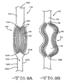
- FIGs. 9 and 10 illustrate another preferred embodiment of a neural interface device 100 according to the present invention.
- the implantable neural interface device 100 comprises a flexible ribbon-type connector 102 having a length extending from a first, proximal connector end 102A to a second, distal connector end 102B, and a width extending between a third, right edge 102C and a fourth, left edge 102D. Further, the connector has a fifth, upper surface 102E spaced from a sixth, lower surface 102F by a thickness 102G ( FIGs. 10A to 10C ).
- the ribbon-type connector 102 is preferably of a flexible polymer-based cable, such as of silicone or polyurethane, but may alternatively be any other suitable planar material. Preferably, the connector 102 is encased in silicone or another suitable biocompatible material.
- the connector 102 includes at least one deformable segment 104 that functions in a similar manner as previously described with respect to the deformable segments 18, 46 of the carrier 12.
- the deformable segment 104 comprises at least one split 106 that extends from a proximal slitted end 106A to a distal slitted end 106B.
- the slit 106 is where the material of the ribbon-type connector 102 has been cut completely through its thickness 102G so that open space exists between adjacent strands 108 of the connector material.
- the slit 106 and, consequently, the open space extends from a proximal end 104A of the deformable segment to a distal end 104B thereof.
- a plurality of slits 106 form a plurality of strands 108 along the length of the deformable segment 104.
- Each strand 108 is narrower and consequently more flexible than the unslit connector 102 and includes at least one conducting trace (not shown), and the like, extending from the first, proximal connector end 102A to the second, distal connector end 102B where the traces electrically connect to at least one electrode cite 22 of the previously described electrode array 14.
- the connector 102 with the deformable segment 104 may be fabricated using MEMS or a roll-to-roll technique, and a lithographic technique may be used to pattern the conductive traces. For instance, masking and etching techniques may be used to etch through specific regions of the planar connector 102 to form the one or more split 106.
- the number of splits 106 and their individual widths may be dependent on various factors, such as intended tissue anatomy of a specific application and manufacturing cost.
- FIGs. 10A to 10D illustrate the connector 102 including the deformable segment 104 may include an undulating or three-dimensional shape 110.
- Undulations 110 facilitate an additional amount of linear expansion or contraction before the connector 102 reaches the tension or compression limits inherent in its material.
- the undulations 110 may be formed in both a slit and unslit portion.
- the undulations 110 in the connector 102 may be formed by placing the planar structure connector 102 shown in FIG. 10A between complementary undulating top and bottom molds 112A and 112B, and applying heat 114 to anneal the structure. As shown in the side view of FIG. 10C and top plan view of FIG.
- the thusly conditioned connector 102 has undulations 110 mirroring those of the molds 112A, 112B.
- FIGs. 10A to 10D primarily show undulations 110 along the axial direction of the connector 102, the connector may additionally and/or alternatively have undulations along the lateral direction or across the width extending from right edge 102C to left edge 102D thereof, or any suitable direction.
- planar connector 102 can be formed into a tubular shape.
- the deformable segments 18, 46 of the neural interface device 10 and the deformable segment 104 of the neural interface device 100 preferably have lengths of from about 0.5 mm to about 2 mm. Moreover, when there is more than one of them in a neural interface device, they are spaced about 1 mm to about 5mm from each other.
- the proximal ends of the implantable neural interface devices 10, 100 are connectable to a second electrical subsystem (not shown) that functions to operate with the electrode array 14.
- the second electrical subsystem may be a printed circuit board with or without on-board integrated circuits, comprise an on-chip circuitry for signal conditioning, filtering, or stimulus generation, be an Application Specific Integrated Circuit (ASIC), a multiplexer chip, a buffer amplifier, an electronics interface, an implantable pulse generator, an implantable rechargeable battery, integrated electronics for real-time signal processing of the commands sent to the stimulation electrodes 52 or received from the recording electrodes 54, integrated electronics for control of any fluidic components, and any other suitable electrical subsystem.
- ASIC Application Specific Integrated Circuit
- the neural interface devices 10, 100 may be coupled to a fixation point within the cranium of a patient.
- a cranial chamber may be attached to the skull, preferably in a cranial burr hole, of a patient, and one or more of the neural interface devices 10, 100 may be coupled to the cranial chamber.
- One embodiment of such a cranial chamber may be similar to that described in U.S. Patent No. 7,548,775 , which is incorporated in its entirety by this reference.
- the neural interface devices 10, 100 may further include one or more fluidic channels that provide for delivery of a fluid (e.g., therapeutic drugs) to inhibit biologic response to the implant or to elicit a therapeutic response.
- a fluid e.g., therapeutic drugs
- Some embodiments of the neural interface devices 10, 100 of the present invention may include any combination of any of them.
- One portion of a neural interface device may comprise features of neural interface device 10 while other portions may include features of the neural interface device 100.
- the deformable segments 18, 46 and 104 may be regularly or irregularly spaced along the length of a neural interface device. For example, it may be desirable to impart greater flexibility to selected regions of the carrier, such as spacing the deformable segments progressively closer together towards a distal end or a proximal end of the carrier. Some of the deformable segments may additionally and/or alternatively be more easily deformed than other deformable segments, which may further provide greater flexibility to selected regions of the neural interface device.
Landscapes
- Health & Medical Sciences (AREA)
- Life Sciences & Earth Sciences (AREA)
- Veterinary Medicine (AREA)
- Public Health (AREA)
- General Health & Medical Sciences (AREA)
- Animal Behavior & Ethology (AREA)
- Engineering & Computer Science (AREA)
- Biomedical Technology (AREA)
- Heart & Thoracic Surgery (AREA)
- Nuclear Medicine, Radiotherapy & Molecular Imaging (AREA)
- Radiology & Medical Imaging (AREA)
- Neurology (AREA)
- Cardiology (AREA)
- Neurosurgery (AREA)
- Medical Informatics (AREA)
- Physics & Mathematics (AREA)
- Biophysics (AREA)
- Pathology (AREA)
- Molecular Biology (AREA)
- Surgery (AREA)
- Orthopedic Medicine & Surgery (AREA)
- Psychology (AREA)
- Electrotherapy Devices (AREA)
Abstract
Description
- This application claims priority from
U.S. Provisional Patent Application Serial No. 61/587,606, filed on January 17, 2012 - This invention relates generally to the implantable medical devices and, more specifically, to an improved implantable neural interface device with a deformable carrier or connector.
- Conventional carriers or connectors for neural interface devices, such as those with electrode arrays for deep brain and central nervous system applications, have a tendency to "drift" after implantation in targeted tissue. This is due, in part, to the mechanical mismatch between the relatively stiff carrier for the neural interface device and the target body tissue and, in part, to tissue regrowth around the neural interface device. Any relative movement between the neural interface device and body tissue can result in the electrode array moving away from the targeted tissue. Thus, there is a need in the implantable medical device field for an improved carrier or connector for an implantable neural interface device. The present invention provides such an improved deformable carrier or connector for an implantable neural interface device.
-
-
FIG. 1 and 1A to 1DC are schematics of aneural interface device 10 according to the present invention including acarrier 12, anelectrical conductor 20, and astylet 32. -
FIG. 2 is a schematic of the implantedneural interface device 10 having been implanted into body tissue. -
FIG 3 is a schematic of a prior artneural interface device 10A after having been implanted in shifted body tissue. -
FIGs. 4 and 4A to 4C are schematics of a first embodiment of thecarrier 12 for theneural interface device 10 includingdeformable segments 18. -
FIG. 4D is an enlarged view of the area indicted inFIG. 4C . -
FIGs. 5A and 5B are schematics of theneural interface device 10 of the present invention after having been implanted in shifted body tissue. -
FIG. 6 is a schematic of another embodiment of tapereddeformable segments 46 for thecarrier 12 of an implantableneural interface device 10 according to the present invention. -
FIG. 6A is a cross-section alongline 6A-6A ofFIG. 6 . -
FIG. 7 is a schematic of anchoring features such as etchedrecesses 48 and through-holes 50 in thecarrier sidewall 16. -
FIG. 8 is a schematic of anelectrode array 14. -
FIGs. 9A to 9B are schematics of another embodiment of adeformable connector 102 for aneural interface device 100 according to the present invention. -
FIGs. 10A to 10D are schematics of a method of manufacturing theneural interface device 100 illustrated inFIGs. 9A and 9B . - Turning now to the drawings,
FIGs. 1 and 1A to 1C illustrate a preferred embodiment of an implantableneural interface device 10 according to the present invention. Theneural interface device 10 is implantable into a wide variety of body tissue including the brain, spinal cord, peripheral nerve, muscle, and/or any suitable neural tissue and comprises acarrier 12 supporting at least oneelectrode array 14. - The
electrode array 14 may be made from a thin-film polymer substrate such that there is a high density of electrode sites at a first end of the array (e.g., the distal end) and bonding regions at a second end of the array (e.g., the proximal end). The polymer substrate is preferably parylene, polyimide, silicone or a suitable combination of organic and inorganic dielectrics, but may additionally and/or alternatively be made of any suitable material. The substrate can also include a dielectric layer comprised of silicon nitride, silicon dioxide, silicon carbide, and mixtures thereof. - The
carrier 12 is preferably of silicone or polyurethane and comprises atubular sidewall 16 having a length extending from aproximal carrier portion 12A to adistal carrier portion 12B. Thedistal carrier portion 12B has astep 12C transition to a thin-walleddistal end 12D. Thestep 12C has a height that substantially matches the thickness of the thin film substrate comprising theelectrode array 14. That way, theelectrode assay 14 is wrapped and otherwise supported at least part way around the circumference of thedistal carrier end 12D to provide a smooth transition to thedistal carrier portion 12B. To facilitate adhesion between thecarrier 12 andelectrode array 14, small non-homogenous perforations may be micromachined into the thin-film substrate to allow for the material of thecarrier 12 to form a robust anchor with theelectrode array 14. - At least one
deformable segment 18 is provided along the length of thecarrier 12 intermediate a firstcarrier sidewall portion 16A and a secondcarrier sidewall portion 16B. As will be described in greater detail hereinafter, thedeformable segment 18 is a portion or location along thecarrier 12 that is compressible, tensile, articulatable, and/or rotatable along an axis thereof, such as a longitudinal axis of the carrier. Compression or extension of thedeformable segment 18 results in translation of thecarrier sidewall portions deformable segment 18 may additionally and/or alternatively bend or rotate or deform in any other suitable manner along any suitable axis. For instance, thedeformable segment 18 may bend or curve to enable thesidewall portions carrier 12. In an alternative embodiment, the entire length of thecarrier 12 is substantially equivalent to adeformable segment 18 such that the carrier is adapted to deform in compression, extension, and/or any other suitable manner. - An
electrical conductor 20 extends from theproximal carrier portion 12A to thedistal carrier portion 12B where the conductor electrically connects to at least oneelectrode site 22 of theelectrode array 14 supported by thedistal carrier end 12D. As will be described in greater detail hereinafter, theelectrode site 22 is exemplary of a stimulation electrode configured for electrical stimulation of body tissue or a recording electrode for recording of physiological data from body tissue. In that respect, thenovel carrier 12 facilitates insertion or implantation of theelectrode array 14 into body tissue and, once implanted, helps mitigate or eliminate drift (movement) of the implantedelectrode array 14 within the tissue. - The
conductor 20 preferably has coiled or otherwise stretchable ordeformable sections 20A that coincide with thedeformable segments 18 in thecarrier 12 of theneural interface device 10. Theconductor 20 is preferably a thin-film structure containing multiple individually conductive traces, but may be a wire or any suitable conductive material. Theconductor 20 may be wound around the external surface of thecarrier 12, wound within a wall of the carrier, or wound around an internal surface of the carrier. The coiling or winding density is preferably selectively varied along the length of thecarrier 12 to modulate the flexibility of theconductor 20. In a preferred embodiment, theconductor 20 include at least one section of lower coiling density corresponding to or aligned with adeformable segment 18 and at least one section of higher coiling density corresponding to or aligned with one of thecarrier sidewall section carrier 12 andcoiled conductor 20 may be deformable in tandem in compression, tension or extension, articulation, rotation and/or any suitable manner. -
FIG. 2 is a schematic illustration of theneural interface device 10 according to the present invention extending through thecranium 24 and into brain tissue. This drawing shows that brain tissue is not necessarily homogenous. For example, the brain tissue is depicted as comprising tissue layers orregions neural interface device 10 has been implanted into the brain tissue with theelectrode array 14 residing at atarget tissue site 28. - Over time, regions of brain matter can become compressed or expanded through tissue changes. A tethered connection of the neural interface device to the cranium or other proximal structures may induce displacement as well. Such non-specific movement of body tissue can displace an implanted electrode array away from the targeted
tissue 28.FIG. 3 shows that relative shifting has occurred between the various tissue layers orregions electrode array 14A of a prior artneural interface device 10A no longer residing at thetarget tissue site 28. The consequence can be diminished or even completely ineffective neural stimulation, which is undesirable. - The
carrier 12 of the presentneural interface device 10 is preferably at least partially made of a flexible material, such as an elastomer. Nitinol is another preferred material for thecarrier 12. Thecarrier 12 is preferably tubular with a substantially cylindrical inner surface and includes one or more lumens 30 (FIG. 1A ), such as for receiving a stylet 32 (FIG. 1C ) therein. Thestylet 32 has a pointed tip at itsdistal end 32A that helps facilitate insertion of theneural interface device 10 into tissue. If desired, thestylet 32 can have alumen 34 for transporting fluids or serving as a passage for moving other devices (not shown) through the stylet/carrier assembly from theproximal carrier portion 12A to thedistal carrier portion 12B and out the stylet end 32A thereof. - The
stylet 32 may be adapted to remain in the tissue coupled to thecarrier 12 and includedeformable segments 36 similar to those 18 of thecarrier 12 that enable compression and/or extension. If provided, thedeformable segments 36 of thestylet 32 are preferably aligned with those of thecarrier 12. That is so compression and extension of thestylet 32 andcarrier 12 correspond to each other. Alternatively, thestylet 32 may be adapted for removal from thecarrier 12 after implantation of theneural interface device 10 into body tissue. -
FIGs. 4 and 4A to 4C illustrate a first embodiment of acarrier 12 according to the present invention. As previously described, thecarrier 12 comprises thetubular sidewall 16 with a substantially cylindrical inner surface having one or moredeformable segments 18 provided at spaced locations along its length. More specifically, thetubular sidewall 16 comprises a plurality of relatively less deformablecarrier sidewall portions deformable segments 18. The lessdeformable sidewall portions 16A to 16E each have a first wall thickness that is substantially uniform around the annular extent thereof. This is illustrated in the cross-sections ofFIGs. 4A and 4C . - As shown in the cross-sections of
FIGs. 4B and 4C , thedeformable segments 18 are provided by an annular thinning of the wall thickness. As shown inFIG. 4D , theexemplary deformable segment 18 shown inFIGs. 4C has a radiusedcurvature 38 from where it connects toproximal sidewall segment 16A and todistal sidewall segment 16B. That is the radiused curvature of the deformable segment has a cross-section along a plane aligned perpendicular to a longitudinal axis of thecarrier 16 that meets theproximal carrier portion 16A of the first wall thickness and curves to a trough having a second wall thickness at about a midpoint to adistal carrier portion 16B of the first wall thickness. In other words, thecarrier segments 16A to 16E, etc. generally have a first wall thickness and thedeformable segments 18 generally have a second wall thickness that is less than the first wall thickness. - According to the first embodiment, the
carrier 12 is of a continuous molded tubular construction with the thinneddeformable segments 18 characterized as a mechanically thinning of thesidewall 16. Thinning of the sidewall can be done by any one of a number of methods including turning thecarrier 12 on a lathe, by selective heat pressing thesidewall 16, and the like. Moreover, thecarrier sidewall segments 16A to 16E and thedeformable segments 18 can be separately manufactured and then serially connected together by thermal sealing, epoxy, or any suitable sealing or coupling method. - As shown in
FIG. 5A , thedeformable segments 18 enable thecarrier 12 and the supportedelectrode array 14 to remain in the correct position and orientation with respect to the targetedtissue 28. Thedeformable segments 18 are more pliable than the remainder of thecarrier sidewall 16 to preferably move in response to forces imparted on thecarrier 12 and theelectrode array 14 by the tissue. As shown inFIG. 5A , thedeformable segments 18 enable thecarrier 12 to move in compression andextension 40.FIG. 5B shows that thedeformable segment 18 enables thecarrier 12 to undergo both bending 42 and rotational 44 movement. As used herein, the term pliable in reference to thedeformable segments 18 means easily bent, relatively more flexible, or relatively suppler. -
FIG. 6 illustrates that adeformable segment 46 does not necessarily require the radiusedcurvature 38 shown fordeformable segment 18 inFIGs. 4C and 4D . Instead, thedeformable segment 46 can have an irregular or graduated cross-sectional shape that is thinnest at aproximal end 46A and gradually thickens as the segment extends to adistal segment end 46B connected to the nextcarrier sidewall segment 16B. There can also be a number ofdeformable segments 46 connected end-to-end intermediate thecarrier sidewall segments deformable segment 46 can be reversed to that shown inFIG. 6 . That would be where thesegment 46 is thickest at the proximalcarrier sidewall segment 16A and thins as it extends to the next, more distalcarrier sidewall segment 16B. - In another embodiment, the
deformable segments 18 are made of a more flexible material or overall composite of materials having a lower elastic modulus than thecarrier segments 16A to 16E, etc. For example, the carrier sidewall segments are of a polymeric material having a durometer ranging from about 75A to about 60A, more preferably of a polymeric material having a durometer ranging from about 70A to about 55A. Then, thedeformable segments - In one embodiment, the
carrier sidewall 16 is of a first polymeric material having a durometer ranging from about 75A to about 60A and thedeformable segment 18 is of a second polymeric material having a durometer ranging from about 50A to 25A. Moreover, thecarrier sidewall 16 of the first polymeric material and thedeformable segment 18 of the second polymeric material have similar thicknesses. - In some embodiments, as shown in
FIG. 7 , the carrier may include one or more anchoring features, such as anetched recess 48 or a through-hole 50 in thecarrier sidewall 16. The anchoring features 48, 50 may help promote tissue regrowth into the carrier structure, thereby improving anchoring of the carrier and/or first electrical subsystem in tissue. Thecarrier sidewall 16 may also be selectively coated with adhesion promoting factors, such as laminin, fibronectin, L1 molecule (Azemi, Cui 2011, Biomaterials), etc., to promote tissue adhesion. - The
electrode array 14 is adapted to provide dynamic tunable electrical interaction with body tissue, and preferably includes a plurality of recording (e.g., sampling or mapping) and/or stimulation electrode sites. For example, the neural interface electrode array may be configured to provide stimulation ranging from macroscale specificity to microscale directional patterning. - As shown in
FIG. 8 , one embodiment of theelectrode array 14 includes sixty-fourstimulation electrodes 52 and thirty-tworecording electrodes 54 positioned axially along and circumferentially around thecarrier 12. Eachstimulation site 52 has a surface area of approximately 0.196 mm2 (diameter approximately 500 µm), but may alternatively have any suitable surface area. Eachrecording site 54 has a surface area of approximately 0.00196 mm2 (diameter approximately 50 µm), but may alternatively have any suitable surface area. Thestimulation sites 52 are positioned such that four sites are equally distributed around the carrier circumference with a center-to-center spacing of approximately 750 µm, and distributed in 16 successive rows equally distributed along the longitudinal or axial direction of the carrier with a row-to-row spacing of approximately 750 µm. A pair ofrecording sites 54 is positioned on opposite sides of thecarrier 12 between each row ofstimulation sites 52. Each pair ofrecording sites 54 is rotated 90 degrees around the carrier with respect to an adjacent pair of recording sites. In alternative embodiments, theelectrode array 14 may include any suitable number ofstimulation electrode sites 52 andrecording sites 54 arranged in any suitable manner. - In another embodiment, the
electrode array 14 includes a plurality of cylindrical electrodes (not shown) spaced apart from each other axially along the length of thecarrier 12. The cylindrical electrodes can be used in monopolar or bipolar modes to deliver approximately spherical potential fields from separate locations along the cylindrical carrier. Furthermore, although thecarrier 12 is preferably a single tube, alternative embodiments may have any suitable shape, such as with branches or forks. -
FIGs. 9 and10 illustrate another preferred embodiment of aneural interface device 100 according to the present invention. The implantableneural interface device 100 comprises a flexible ribbon-type connector 102 having a length extending from a first,proximal connector end 102A to a second,distal connector end 102B, and a width extending between a third,right edge 102C and a fourth, leftedge 102D. Further, the connector has a fifth,upper surface 102E spaced from a sixth,lower surface 102F by athickness 102G (FIGs. 10A to 10C ). The ribbon-type connector 102 is preferably of a flexible polymer-based cable, such as of silicone or polyurethane, but may alternatively be any other suitable planar material. Preferably, theconnector 102 is encased in silicone or another suitable biocompatible material. - The
connector 102 includes at least onedeformable segment 104 that functions in a similar manner as previously described with respect to thedeformable segments carrier 12. Thedeformable segment 104 comprises at least onesplit 106 that extends from a proximalslitted end 106A to a distalslitted end 106B. Theslit 106 is where the material of the ribbon-type connector 102 has been cut completely through itsthickness 102G so that open space exists betweenadjacent strands 108 of the connector material. Theslit 106 and, consequently, the open space extends from aproximal end 104A of the deformable segment to adistal end 104B thereof. More preferably, a plurality ofslits 106 form a plurality ofstrands 108 along the length of thedeformable segment 104. Eachstrand 108 is narrower and consequently more flexible than theunslit connector 102 and includes at least one conducting trace (not shown), and the like, extending from the first,proximal connector end 102A to the second,distal connector end 102B where the traces electrically connect to at least one electrode cite 22 of the previously describedelectrode array 14. - In this embodiment, the
connector 102 with thedeformable segment 104 may be fabricated using MEMS or a roll-to-roll technique, and a lithographic technique may be used to pattern the conductive traces. For instance, masking and etching techniques may be used to etch through specific regions of theplanar connector 102 to form the one ormore split 106. The number ofsplits 106 and their individual widths may be dependent on various factors, such as intended tissue anatomy of a specific application and manufacturing cost. -
FIGs. 10A to 10D illustrate theconnector 102 including thedeformable segment 104 may include an undulating or three-dimensional shape 110.Undulations 110 facilitate an additional amount of linear expansion or contraction before theconnector 102 reaches the tension or compression limits inherent in its material. Theundulations 110 may be formed in both a slit and unslit portion. In that respect, theundulations 110 in theconnector 102 may be formed by placing theplanar structure connector 102 shown inFIG. 10A between complementary undulating top andbottom molds heat 114 to anneal the structure. As shown in the side view ofFIG. 10C and top plan view ofFIG. 10D , the thuslyconditioned connector 102 has undulations 110 mirroring those of themolds FIGs. 10A to 10D primarily showundulations 110 along the axial direction of theconnector 102, the connector may additionally and/or alternatively have undulations along the lateral direction or across the width extending fromright edge 102C to leftedge 102D thereof, or any suitable direction. - If desired, the
planar connector 102 can be formed into a tubular shape. - The
deformable segments neural interface device 10 and thedeformable segment 104 of theneural interface device 100 preferably have lengths of from about 0.5 mm to about 2 mm. Moreover, when there is more than one of them in a neural interface device, they are spaced about 1 mm to about 5mm from each other. - The proximal ends of the implantable
neural interface devices electrode array 14. For example, the second electrical subsystem may be a printed circuit board with or without on-board integrated circuits, comprise an on-chip circuitry for signal conditioning, filtering, or stimulus generation, be an Application Specific Integrated Circuit (ASIC), a multiplexer chip, a buffer amplifier, an electronics interface, an implantable pulse generator, an implantable rechargeable battery, integrated electronics for real-time signal processing of the commands sent to thestimulation electrodes 52 or received from therecording electrodes 54, integrated electronics for control of any fluidic components, and any other suitable electrical subsystem. - In one embodiment, the
neural interface devices neural interface devices U.S. Patent No. 7,548,775 , which is incorporated in its entirety by this reference. Theneural interface devices - Some embodiments of the
neural interface devices neural interface device 10 while other portions may include features of theneural interface device 100. Moreover, thedeformable segments - A person skilled in the art will recognize from the previous detailed description including the drawing figures, that modifications and changes can be made to the preferred embodiments of the present invention without departing from the scope of the invention defined in the following claims.
Claims (13)
- A neural interface device, which comprises:a) a ribbon-type connector comprising a connector sidewall extending along a first length from a connector proximal end to a connector distal portion having a distal end, wherein the connector proximal end is electrically connectable to a medical device;b) at least one electrode supported on the distal connector portion, wherein the electrode is configured for at least one of electrical stimulation of body tissue and sensing of physiological characteristics of the body tissue;c) an electrical conductor that extends along the connector from the connector proximal end to the connector distal portion where it is electrically connected to the electrode; andd) a deformable segment of the connector sidewall at an intermediate location between the connector proximal end and the connector distal end, wherein the deformable segment is relatively more pliable than the remainder of the connector sidewall.
- The neural interface device of claim 1 wherein the deformable segment comprises at least one slit having a slit length that extends part way along the first length of the connector sidewall and is completely through a thickness thereof.
- The neural interface device of claim 1 wherein there is a plurality of slits, each having a slit length that extends part way along the first length of the connector sidewall.
- The neural interface device of claim 3 wherein the slits are provided at spaced location around an annular extent of the connector sidewall.
- The neural interface device of claim 1 wherein the slit has a undulating shape.
- The neural interface device of claim 1 wherein the connector is of a polymeric material.
- The neural interface device of claim 1 wherein the connector has a planar structure that is rollable into a tubular shape.
- The neural interface device of claim 1 wherein there are at least two deformable segments at spaced locations along the first length of the connector.
- The neural interface device of claim 1 wherein the electrical conductor is relatively more stretchable at a location coinciding with the deformable segment of the connector.
- The neural interface device of claim 1 wherein the connector sidewall has a substantially cylindrical inner surface.
- The neural interface device of claim 1 wherein the at least one electrode is supported on a substrate of a polymeric material selected from the group consisting of parylene, polyimide, silicone, and mixtures thereof.
- The neural interface device of claim 1 wherein the distal portion of the connector has a step transition to a thinner connector sidewall portion that is sized to support the electrode supported on the polymeric substrate.
- The neural interface device of claim 1 wherein the deformable segment is compressible, tensile, articulatable, and rotatable.
Applications Claiming Priority (1)
| Application Number | Priority Date | Filing Date | Title |
|---|---|---|---|
| US201261587606P | 2012-01-17 | 2012-01-17 |
Publications (2)
| Publication Number | Publication Date |
|---|---|
| EP2617458A1 true EP2617458A1 (en) | 2013-07-24 |
| EP2617458B1 EP2617458B1 (en) | 2016-06-22 |
Family
ID=47603349
Family Applications (2)
| Application Number | Title | Priority Date | Filing Date |
|---|---|---|---|
| EP13151597.5A Not-in-force EP2617459B1 (en) | 2012-01-17 | 2013-01-17 | Implantable neural interface device with a deformable carrier |
| EP13151575.1A Not-in-force EP2617458B1 (en) | 2012-01-17 | 2013-01-17 | Implantable neural interface device with a connector having a slitted deformable section |
Family Applications Before (1)
| Application Number | Title | Priority Date | Filing Date |
|---|---|---|---|
| EP13151597.5A Not-in-force EP2617459B1 (en) | 2012-01-17 | 2013-01-17 | Implantable neural interface device with a deformable carrier |
Country Status (2)
| Country | Link |
|---|---|
| US (3) | US8958890B2 (en) |
| EP (2) | EP2617459B1 (en) |
Families Citing this family (26)
| Publication number | Priority date | Publication date | Assignee | Title |
|---|---|---|---|---|
| EP2313148B1 (en) | 2008-07-30 | 2013-08-21 | Ecole Polytechnique Fédérale de Lausanne | Apparatus for optimized stimulation of a neurological target |
| EP3563902B1 (en) | 2008-11-12 | 2021-07-14 | Ecole Polytechnique Fédérale de Lausanne | Microfabricated neurostimulation device |
| US9549708B2 (en) | 2010-04-01 | 2017-01-24 | Ecole Polytechnique Federale De Lausanne | Device for interacting with neurological tissue and methods of making and using the same |
| EP2789364A1 (en) * | 2013-04-08 | 2014-10-15 | Sapiens Steering Brain Stimulation B.V. | A lead, especially a lead for neural applications |
| JP2016523125A (en) | 2013-05-30 | 2016-08-08 | グラハム エイチ. クリーシー | Local nervous stimulation |
| US11229789B2 (en) | 2013-05-30 | 2022-01-25 | Neurostim Oab, Inc. | Neuro activator with controller |
| EP3476430B1 (en) | 2014-05-16 | 2020-07-01 | Aleva Neurotherapeutics SA | Device for interacting with neurological tissue |
| US11311718B2 (en) | 2014-05-16 | 2022-04-26 | Aleva Neurotherapeutics Sa | Device for interacting with neurological tissue and methods of making and using the same |
| US9474894B2 (en) | 2014-08-27 | 2016-10-25 | Aleva Neurotherapeutics | Deep brain stimulation lead |
| US11077301B2 (en) | 2015-02-21 | 2021-08-03 | NeurostimOAB, Inc. | Topical nerve stimulator and sensor for bladder control |
| US20210213279A1 (en) * | 2016-09-16 | 2021-07-15 | Precision Neuroscience LLC | Conformal electrode arrays for electrophysiologic recording and neural stimulation within the cerebral ventricles and cerebral vasculature |
| WO2018075396A1 (en) * | 2016-10-17 | 2018-04-26 | The Charlotte-Mecklenburg Hospital Authority D/B/A/ Carolinas Healthcare System | Devices, systems, and methods for treating cardiac arrhythmias |
| US10716935B2 (en) * | 2016-11-04 | 2020-07-21 | Boston Scientific Neuromodulation Corporation | Electrical stimulation leads, systems and methods for stimulation of dorsal root ganglia |
| US10908038B2 (en) * | 2017-01-31 | 2021-02-02 | The Regents Of The University Of California | Stretchable, conductive interconnect and/or sensor and method of making the same |
| US11547849B2 (en) | 2017-06-07 | 2023-01-10 | Neuronexus Technologies, Inc. | Systems and methods for ruggedized penetrating medical electrode arrays |
| US10953225B2 (en) | 2017-11-07 | 2021-03-23 | Neurostim Oab, Inc. | Non-invasive nerve activator with adaptive circuit |
| US20210045690A1 (en) * | 2018-03-01 | 2021-02-18 | Universitat Basel Vizerektorat Forschung | Neural probe for electrostimulation or recording and fabrication process for such a probe |
| US10702692B2 (en) | 2018-03-02 | 2020-07-07 | Aleva Neurotherapeutics | Neurostimulation device |
| AU2020234581A1 (en) * | 2019-03-11 | 2021-10-28 | Athos PATSALIDES | Intradural neural electrodes |
| US20220175320A1 (en) * | 2019-03-22 | 2022-06-09 | Verily Life Sciences Llc | Thin-Film Lead Assemblies And Neural Interfaces |
| WO2020264214A1 (en) | 2019-06-26 | 2020-12-30 | Neurostim Technologies Llc | Non-invasive nerve activator with adaptive circuit |
| US12329963B2 (en) * | 2019-11-04 | 2025-06-17 | Verily Life Sciences Llc | Anatomically contoured stimulation leads for high density neural interface |
| WO2021126921A1 (en) | 2019-12-16 | 2021-06-24 | Neurostim Solutions, Llc | Non-invasive nerve activator with boosted charge delivery |
| RU206363U1 (en) * | 2020-05-15 | 2021-09-07 | федеральное государственное бюджетное образовательное учреждение высшего образования "Санкт-Петербургский государственный университет" | NEURAL IMPLANT |
| CN114469110B (en) * | 2022-03-10 | 2025-10-21 | 武汉衷华脑机融合科技发展有限公司 | A connecting line structure |
| CN119033386B (en) * | 2024-10-27 | 2025-03-14 | 科斗(苏州)脑机科技有限公司 | Nerve electric signal acquisition and stimulation unit with elasticity compensation mechanism |
Citations (4)
| Publication number | Priority date | Publication date | Assignee | Title |
|---|---|---|---|---|
| US20070213795A1 (en) * | 2003-05-08 | 2007-09-13 | Kerry Bradley | Implantable medical lead |
| US20080039917A1 (en) * | 2006-04-28 | 2008-02-14 | Cross Thomas E | Implantable medical leads and lead assemblies with improved flexibility and extensibility to facilitate body movements |
| US7548775B2 (en) | 2003-10-21 | 2009-06-16 | The Regents Of The University Of Michigan | Intracranial neural interface system |
| US20110093052A1 (en) * | 2009-10-16 | 2011-04-21 | Anderson David J | Neural interface system |
Family Cites Families (10)
| Publication number | Priority date | Publication date | Assignee | Title |
|---|---|---|---|---|
| US5893847A (en) * | 1993-03-16 | 1999-04-13 | Ep Technologies, Inc. | Multiple electrode support structures with slotted hub and hoop spline elements |
| US5562722A (en) * | 1994-03-14 | 1996-10-08 | Medical Evaluation Devices & Instruments Corp. | Multiple electrode catheter |
| US7363082B2 (en) | 2005-03-24 | 2008-04-22 | Synecor Llc | Flexible hermetic enclosure for implantable medical devices |
| EP1981584B1 (en) | 2006-02-03 | 2015-05-13 | Interventional Autonomics Corporation | Intravascular device for neuromodulation |
| WO2007117538A2 (en) | 2006-04-03 | 2007-10-18 | Innerpulse, Inc. | Flexible interconnect assembly for implantable medical devices |
| US8170638B2 (en) | 2006-09-11 | 2012-05-01 | University Of Florida Research Foundation, Inc. | MEMS flexible substrate neural probe and method of fabricating same |
| US10856904B2 (en) | 2006-11-30 | 2020-12-08 | Medtronic, Inc. | Flexible introducer |
| US8224417B2 (en) | 2007-10-17 | 2012-07-17 | Neuronexus Technologies, Inc. | Guide tube for an implantable device system |
| US20090240314A1 (en) | 2008-03-24 | 2009-09-24 | Kong K C | Implantable electrode lead system with a three dimensional arrangement and method of making the same |
| US10130274B2 (en) | 2010-06-15 | 2018-11-20 | Ecole Polytechnique Federale De Lausanne (Epfl) | PDMS-based stretchable multi-electrode and chemotrode array for epidural and subdural neuronal recording, electrical stimulation and drug delivery |
-
2013
- 2013-01-14 US US13/740,310 patent/US8958890B2/en active Active
- 2013-01-15 US US13/741,864 patent/US8972026B2/en active Active
- 2013-01-17 EP EP13151597.5A patent/EP2617459B1/en not_active Not-in-force
- 2013-01-17 EP EP13151575.1A patent/EP2617458B1/en not_active Not-in-force
-
2015
- 2015-02-17 US US14/623,991 patent/US9289151B2/en not_active Expired - Fee Related
Patent Citations (4)
| Publication number | Priority date | Publication date | Assignee | Title |
|---|---|---|---|---|
| US20070213795A1 (en) * | 2003-05-08 | 2007-09-13 | Kerry Bradley | Implantable medical lead |
| US7548775B2 (en) | 2003-10-21 | 2009-06-16 | The Regents Of The University Of Michigan | Intracranial neural interface system |
| US20080039917A1 (en) * | 2006-04-28 | 2008-02-14 | Cross Thomas E | Implantable medical leads and lead assemblies with improved flexibility and extensibility to facilitate body movements |
| US20110093052A1 (en) * | 2009-10-16 | 2011-04-21 | Anderson David J | Neural interface system |
Also Published As
| Publication number | Publication date |
|---|---|
| EP2617459A1 (en) | 2013-07-24 |
| EP2617458B1 (en) | 2016-06-22 |
| US20130184795A1 (en) | 2013-07-18 |
| US20130184799A1 (en) | 2013-07-18 |
| US20150164360A1 (en) | 2015-06-18 |
| US8958890B2 (en) | 2015-02-17 |
| US8972026B2 (en) | 2015-03-03 |
| US9289151B2 (en) | 2016-03-22 |
| EP2617459B1 (en) | 2016-05-04 |
Similar Documents
| Publication | Publication Date | Title |
|---|---|---|
| EP2617458B1 (en) | Implantable neural interface device with a connector having a slitted deformable section | |
| US11324945B2 (en) | Neural interface system | |
| US8565894B2 (en) | Three-dimensional system of electrode leads | |
| JP7802192B2 (en) | Neural interface with supporting structure | |
| US8332046B2 (en) | Neural interface system | |
| US9545510B2 (en) | Directional lead assembly with electrode anchoring prongs | |
| US20220047845A1 (en) | Catheter Comprising a Flexible Flat Cable and FPCB and Method for Producing It | |
| EP2393548A2 (en) | Implantable electrode with variable mechanical modulation wiring | |
| EP1257320A1 (en) | Implantable stimulation lead | |
| US11129986B2 (en) | Implantable stimulator with a conformable foil like electrode array | |
| US12109408B2 (en) | Implantable electrical stimulation device with a flexible electrode | |
| US11318319B2 (en) | Implantable stimulator with a conformable foil-like electrode array | |
| KR101218188B1 (en) | Intelligent Nerval element capable of communicating data with external module | |
| US10022533B2 (en) | Reinforcement member for a medical lead | |
| US12246182B2 (en) | Implantable restraint and stimulation device configured for explantation |
Legal Events
| Date | Code | Title | Description |
|---|---|---|---|
| PUAI | Public reference made under article 153(3) epc to a published international application that has entered the european phase |
Free format text: ORIGINAL CODE: 0009012 |
|
| AK | Designated contracting states |
Kind code of ref document: A1 Designated state(s): AL AT BE BG CH CY CZ DE DK EE ES FI FR GB GR HR HU IE IS IT LI LT LU LV MC MK MT NL NO PL PT RO RS SE SI SK SM TR |
|
| AX | Request for extension of the european patent |
Extension state: BA ME |
|
| 17P | Request for examination filed |
Effective date: 20140124 |
|
| RBV | Designated contracting states (corrected) |
Designated state(s): AL AT BE BG CH CY CZ DE DK EE ES FI FR GB GR HR HU IE IS IT LI LT LU LV MC MK MT NL NO PL PT RO RS SE SI SK SM TR |
|
| GRAP | Despatch of communication of intention to grant a patent |
Free format text: ORIGINAL CODE: EPIDOSNIGR1 |
|
| RIC1 | Information provided on ipc code assigned before grant |
Ipc: A61B 5/04 20060101ALN20150602BHEP Ipc: A61N 1/36 20060101ALI20150602BHEP Ipc: A61N 1/05 20060101AFI20150602BHEP |
|
| INTG | Intention to grant announced |
Effective date: 20150626 |
|
| RIC1 | Information provided on ipc code assigned before grant |
Ipc: A61N 1/36 20060101ALI20151116BHEP Ipc: A61N 1/05 20060101AFI20151116BHEP Ipc: A61B 5/04 20060101ALN20151116BHEP |
|
| INTG | Intention to grant announced |
Effective date: 20151208 |
|
| RAP1 | Party data changed (applicant data changed or rights of an application transferred) |
Owner name: GREATBATCH LTD. |
|
| RAP1 | Party data changed (applicant data changed or rights of an application transferred) |
Owner name: NEURONEXUS TECHNOLOGIES, INC. |
|
| GRAS | Grant fee paid |
Free format text: ORIGINAL CODE: EPIDOSNIGR3 |
|
| GRAA | (expected) grant |
Free format text: ORIGINAL CODE: 0009210 |
|
| AK | Designated contracting states |
Kind code of ref document: B1 Designated state(s): AL AT BE BG CH CY CZ DE DK EE ES FI FR GB GR HR HU IE IS IT LI LT LU LV MC MK MT NL NO PL PT RO RS SE SI SK SM TR |
|
| REG | Reference to a national code |
Ref country code: GB Ref legal event code: FG4D |
|
| REG | Reference to a national code |
Ref country code: CH Ref legal event code: EP |
|
| REG | Reference to a national code |
Ref country code: IE Ref legal event code: FG4D |
|
| REG | Reference to a national code |
Ref country code: AT Ref legal event code: REF Ref document number: 807313 Country of ref document: AT Kind code of ref document: T Effective date: 20160715 |
|
| REG | Reference to a national code |
Ref country code: DE Ref legal event code: R096 Ref document number: 602013008684 Country of ref document: DE |
|
| REG | Reference to a national code |
Ref country code: LT Ref legal event code: MG4D |
|
| REG | Reference to a national code |
Ref country code: NL Ref legal event code: MP Effective date: 20160622 |
|
| PG25 | Lapsed in a contracting state [announced via postgrant information from national office to epo] |
Ref country code: FI Free format text: LAPSE BECAUSE OF FAILURE TO SUBMIT A TRANSLATION OF THE DESCRIPTION OR TO PAY THE FEE WITHIN THE PRESCRIBED TIME-LIMIT Effective date: 20160622 Ref country code: LT Free format text: LAPSE BECAUSE OF FAILURE TO SUBMIT A TRANSLATION OF THE DESCRIPTION OR TO PAY THE FEE WITHIN THE PRESCRIBED TIME-LIMIT Effective date: 20160622 Ref country code: NO Free format text: LAPSE BECAUSE OF FAILURE TO SUBMIT A TRANSLATION OF THE DESCRIPTION OR TO PAY THE FEE WITHIN THE PRESCRIBED TIME-LIMIT Effective date: 20160922 |
|
| REG | Reference to a national code |
Ref country code: AT Ref legal event code: MK05 Ref document number: 807313 Country of ref document: AT Kind code of ref document: T Effective date: 20160622 |
|
| PG25 | Lapsed in a contracting state [announced via postgrant information from national office to epo] |
Ref country code: GR Free format text: LAPSE BECAUSE OF FAILURE TO SUBMIT A TRANSLATION OF THE DESCRIPTION OR TO PAY THE FEE WITHIN THE PRESCRIBED TIME-LIMIT Effective date: 20160923 Ref country code: LV Free format text: LAPSE BECAUSE OF FAILURE TO SUBMIT A TRANSLATION OF THE DESCRIPTION OR TO PAY THE FEE WITHIN THE PRESCRIBED TIME-LIMIT Effective date: 20160622 Ref country code: SE Free format text: LAPSE BECAUSE OF FAILURE TO SUBMIT A TRANSLATION OF THE DESCRIPTION OR TO PAY THE FEE WITHIN THE PRESCRIBED TIME-LIMIT Effective date: 20160622 Ref country code: HR Free format text: LAPSE BECAUSE OF FAILURE TO SUBMIT A TRANSLATION OF THE DESCRIPTION OR TO PAY THE FEE WITHIN THE PRESCRIBED TIME-LIMIT Effective date: 20160622 Ref country code: NL Free format text: LAPSE BECAUSE OF FAILURE TO SUBMIT A TRANSLATION OF THE DESCRIPTION OR TO PAY THE FEE WITHIN THE PRESCRIBED TIME-LIMIT Effective date: 20160622 Ref country code: RS Free format text: LAPSE BECAUSE OF FAILURE TO SUBMIT A TRANSLATION OF THE DESCRIPTION OR TO PAY THE FEE WITHIN THE PRESCRIBED TIME-LIMIT Effective date: 20160622 |
|
| REG | Reference to a national code |
Ref country code: FR Ref legal event code: PLFP Year of fee payment: 5 |
|
| PG25 | Lapsed in a contracting state [announced via postgrant information from national office to epo] |
Ref country code: RO Free format text: LAPSE BECAUSE OF FAILURE TO SUBMIT A TRANSLATION OF THE DESCRIPTION OR TO PAY THE FEE WITHIN THE PRESCRIBED TIME-LIMIT Effective date: 20160622 Ref country code: SK Free format text: LAPSE BECAUSE OF FAILURE TO SUBMIT A TRANSLATION OF THE DESCRIPTION OR TO PAY THE FEE WITHIN THE PRESCRIBED TIME-LIMIT Effective date: 20160622 Ref country code: CZ Free format text: LAPSE BECAUSE OF FAILURE TO SUBMIT A TRANSLATION OF THE DESCRIPTION OR TO PAY THE FEE WITHIN THE PRESCRIBED TIME-LIMIT Effective date: 20160622 Ref country code: IS Free format text: LAPSE BECAUSE OF FAILURE TO SUBMIT A TRANSLATION OF THE DESCRIPTION OR TO PAY THE FEE WITHIN THE PRESCRIBED TIME-LIMIT Effective date: 20161022 Ref country code: EE Free format text: LAPSE BECAUSE OF FAILURE TO SUBMIT A TRANSLATION OF THE DESCRIPTION OR TO PAY THE FEE WITHIN THE PRESCRIBED TIME-LIMIT Effective date: 20160622 Ref country code: IT Free format text: LAPSE BECAUSE OF FAILURE TO SUBMIT A TRANSLATION OF THE DESCRIPTION OR TO PAY THE FEE WITHIN THE PRESCRIBED TIME-LIMIT Effective date: 20160622 |
|
| PG25 | Lapsed in a contracting state [announced via postgrant information from national office to epo] |
Ref country code: ES Free format text: LAPSE BECAUSE OF FAILURE TO SUBMIT A TRANSLATION OF THE DESCRIPTION OR TO PAY THE FEE WITHIN THE PRESCRIBED TIME-LIMIT Effective date: 20160622 Ref country code: AT Free format text: LAPSE BECAUSE OF FAILURE TO SUBMIT A TRANSLATION OF THE DESCRIPTION OR TO PAY THE FEE WITHIN THE PRESCRIBED TIME-LIMIT Effective date: 20160622 Ref country code: BE Free format text: LAPSE BECAUSE OF FAILURE TO SUBMIT A TRANSLATION OF THE DESCRIPTION OR TO PAY THE FEE WITHIN THE PRESCRIBED TIME-LIMIT Effective date: 20160622 Ref country code: PL Free format text: LAPSE BECAUSE OF FAILURE TO SUBMIT A TRANSLATION OF THE DESCRIPTION OR TO PAY THE FEE WITHIN THE PRESCRIBED TIME-LIMIT Effective date: 20160622 Ref country code: PT Free format text: LAPSE BECAUSE OF FAILURE TO SUBMIT A TRANSLATION OF THE DESCRIPTION OR TO PAY THE FEE WITHIN THE PRESCRIBED TIME-LIMIT Effective date: 20161024 Ref country code: SM Free format text: LAPSE BECAUSE OF FAILURE TO SUBMIT A TRANSLATION OF THE DESCRIPTION OR TO PAY THE FEE WITHIN THE PRESCRIBED TIME-LIMIT Effective date: 20160622 |
|
| REG | Reference to a national code |
Ref country code: DE Ref legal event code: R097 Ref document number: 602013008684 Country of ref document: DE |
|
| PLBE | No opposition filed within time limit |
Free format text: ORIGINAL CODE: 0009261 |
|
| STAA | Information on the status of an ep patent application or granted ep patent |
Free format text: STATUS: NO OPPOSITION FILED WITHIN TIME LIMIT |
|
| RAP2 | Party data changed (patent owner data changed or rights of a patent transferred) |
Owner name: NEURONEXUS TECHNOLOGIES, INC. |
|
| 26N | No opposition filed |
Effective date: 20170323 |
|
| PG25 | Lapsed in a contracting state [announced via postgrant information from national office to epo] |
Ref country code: DK Free format text: LAPSE BECAUSE OF FAILURE TO SUBMIT A TRANSLATION OF THE DESCRIPTION OR TO PAY THE FEE WITHIN THE PRESCRIBED TIME-LIMIT Effective date: 20160622 |
|
| PG25 | Lapsed in a contracting state [announced via postgrant information from national office to epo] |
Ref country code: SI Free format text: LAPSE BECAUSE OF FAILURE TO SUBMIT A TRANSLATION OF THE DESCRIPTION OR TO PAY THE FEE WITHIN THE PRESCRIBED TIME-LIMIT Effective date: 20160622 |
|
| REG | Reference to a national code |
Ref country code: CH Ref legal event code: PL |
|
| GBPC | Gb: european patent ceased through non-payment of renewal fee |
Effective date: 20170117 |
|
| PG25 | Lapsed in a contracting state [announced via postgrant information from national office to epo] |
Ref country code: MC Free format text: LAPSE BECAUSE OF FAILURE TO SUBMIT A TRANSLATION OF THE DESCRIPTION OR TO PAY THE FEE WITHIN THE PRESCRIBED TIME-LIMIT Effective date: 20160622 |
|
| PG25 | Lapsed in a contracting state [announced via postgrant information from national office to epo] |
Ref country code: LI Free format text: LAPSE BECAUSE OF NON-PAYMENT OF DUE FEES Effective date: 20170131 Ref country code: CH Free format text: LAPSE BECAUSE OF NON-PAYMENT OF DUE FEES Effective date: 20170131 |
|
| REG | Reference to a national code |
Ref country code: IE Ref legal event code: MM4A |
|
| PG25 | Lapsed in a contracting state [announced via postgrant information from national office to epo] |
Ref country code: LU Free format text: LAPSE BECAUSE OF NON-PAYMENT OF DUE FEES Effective date: 20170117 Ref country code: GB Free format text: LAPSE BECAUSE OF NON-PAYMENT OF DUE FEES Effective date: 20170117 |
|
| REG | Reference to a national code |
Ref country code: FR Ref legal event code: PLFP Year of fee payment: 6 |
|
| PG25 | Lapsed in a contracting state [announced via postgrant information from national office to epo] |
Ref country code: IE Free format text: LAPSE BECAUSE OF NON-PAYMENT OF DUE FEES Effective date: 20170117 |
|
| PG25 | Lapsed in a contracting state [announced via postgrant information from national office to epo] |
Ref country code: MT Free format text: LAPSE BECAUSE OF NON-PAYMENT OF DUE FEES Effective date: 20170117 |
|
| PG25 | Lapsed in a contracting state [announced via postgrant information from national office to epo] |
Ref country code: AL Free format text: LAPSE BECAUSE OF FAILURE TO SUBMIT A TRANSLATION OF THE DESCRIPTION OR TO PAY THE FEE WITHIN THE PRESCRIBED TIME-LIMIT Effective date: 20160622 |
|
| PG25 | Lapsed in a contracting state [announced via postgrant information from national office to epo] |
Ref country code: HU Free format text: LAPSE BECAUSE OF FAILURE TO SUBMIT A TRANSLATION OF THE DESCRIPTION OR TO PAY THE FEE WITHIN THE PRESCRIBED TIME-LIMIT; INVALID AB INITIO Effective date: 20130117 |
|
| PG25 | Lapsed in a contracting state [announced via postgrant information from national office to epo] |
Ref country code: BG Free format text: LAPSE BECAUSE OF FAILURE TO SUBMIT A TRANSLATION OF THE DESCRIPTION OR TO PAY THE FEE WITHIN THE PRESCRIBED TIME-LIMIT Effective date: 20160622 |
|
| PG25 | Lapsed in a contracting state [announced via postgrant information from national office to epo] |
Ref country code: CY Free format text: LAPSE BECAUSE OF NON-PAYMENT OF DUE FEES Effective date: 20160622 |
|
| PG25 | Lapsed in a contracting state [announced via postgrant information from national office to epo] |
Ref country code: MK Free format text: LAPSE BECAUSE OF FAILURE TO SUBMIT A TRANSLATION OF THE DESCRIPTION OR TO PAY THE FEE WITHIN THE PRESCRIBED TIME-LIMIT Effective date: 20160622 |
|
| PG25 | Lapsed in a contracting state [announced via postgrant information from national office to epo] |
Ref country code: TR Free format text: LAPSE BECAUSE OF FAILURE TO SUBMIT A TRANSLATION OF THE DESCRIPTION OR TO PAY THE FEE WITHIN THE PRESCRIBED TIME-LIMIT Effective date: 20160622 |
|
| PGFP | Annual fee paid to national office [announced via postgrant information from national office to epo] |
Ref country code: FR Payment date: 20230125 Year of fee payment: 11 |
|
| PGFP | Annual fee paid to national office [announced via postgrant information from national office to epo] |
Ref country code: DE Payment date: 20230127 Year of fee payment: 11 |
|
| REG | Reference to a national code |
Ref country code: DE Ref legal event code: R119 Ref document number: 602013008684 Country of ref document: DE |
|
| PG25 | Lapsed in a contracting state [announced via postgrant information from national office to epo] |
Ref country code: DE Free format text: LAPSE BECAUSE OF NON-PAYMENT OF DUE FEES Effective date: 20240801 |
|
| PG25 | Lapsed in a contracting state [announced via postgrant information from national office to epo] |
Ref country code: FR Free format text: LAPSE BECAUSE OF NON-PAYMENT OF DUE FEES Effective date: 20240131 |
|
| PG25 | Lapsed in a contracting state [announced via postgrant information from national office to epo] |
Ref country code: FR Free format text: LAPSE BECAUSE OF NON-PAYMENT OF DUE FEES Effective date: 20240131 Ref country code: DE Free format text: LAPSE BECAUSE OF NON-PAYMENT OF DUE FEES Effective date: 20240801 |