EP2616876B1 - System for retarding progression of myopia - Google Patents
System for retarding progression of myopia Download PDFInfo
- Publication number
- EP2616876B1 EP2616876B1 EP10857121.7A EP10857121A EP2616876B1 EP 2616876 B1 EP2616876 B1 EP 2616876B1 EP 10857121 A EP10857121 A EP 10857121A EP 2616876 B1 EP2616876 B1 EP 2616876B1
- Authority
- EP
- European Patent Office
- Prior art keywords
- zones
- correcting
- zone
- defocusing
- lens
- Prior art date
- Legal status (The legal status is an assumption and is not a legal conclusion. Google has not performed a legal analysis and makes no representation as to the accuracy of the status listed.)
- Revoked
Links
Images
Classifications
-
- G—PHYSICS
- G02—OPTICS
- G02C—SPECTACLES; SUNGLASSES OR GOGGLES INSOFAR AS THEY HAVE THE SAME FEATURES AS SPECTACLES; CONTACT LENSES
- G02C7/00—Optical parts
- G02C7/02—Lenses; Lens systems ; Methods of designing lenses
- G02C7/04—Contact lenses for the eyes
- G02C7/041—Contact lenses for the eyes bifocal; multifocal
- G02C7/044—Annular configuration, e.g. pupil tuned
-
- A—HUMAN NECESSITIES
- A61—MEDICAL OR VETERINARY SCIENCE; HYGIENE
- A61F—FILTERS IMPLANTABLE INTO BLOOD VESSELS; PROSTHESES; DEVICES PROVIDING PATENCY TO, OR PREVENTING COLLAPSING OF, TUBULAR STRUCTURES OF THE BODY, e.g. STENTS; ORTHOPAEDIC, NURSING OR CONTRACEPTIVE DEVICES; FOMENTATION; TREATMENT OR PROTECTION OF EYES OR EARS; BANDAGES, DRESSINGS OR ABSORBENT PADS; FIRST-AID KITS
- A61F2/00—Filters implantable into blood vessels; Prostheses, i.e. artificial substitutes or replacements for parts of the body; Appliances for connecting them with the body; Devices providing patency to, or preventing collapsing of, tubular structures of the body, e.g. stents
- A61F2/02—Prostheses implantable into the body
- A61F2/14—Eye parts, e.g. lenses or corneal implants; Artificial eyes
-
- G—PHYSICS
- G02—OPTICS
- G02C—SPECTACLES; SUNGLASSES OR GOGGLES INSOFAR AS THEY HAVE THE SAME FEATURES AS SPECTACLES; CONTACT LENSES
- G02C7/00—Optical parts
- G02C7/02—Lenses; Lens systems ; Methods of designing lenses
- G02C7/04—Contact lenses for the eyes
- G02C7/041—Contact lenses for the eyes bifocal; multifocal
- G02C7/042—Simultaneous type
-
- G—PHYSICS
- G02—OPTICS
- G02C—SPECTACLES; SUNGLASSES OR GOGGLES INSOFAR AS THEY HAVE THE SAME FEATURES AS SPECTACLES; CONTACT LENSES
- G02C2202/00—Generic optical aspects applicable to one or more of the subgroups of G02C7/00
- G02C2202/24—Myopia progression prevention
-
- G—PHYSICS
- G02—OPTICS
- G02C—SPECTACLES; SUNGLASSES OR GOGGLES INSOFAR AS THEY HAVE THE SAME FEATURES AS SPECTACLES; CONTACT LENSES
- G02C7/00—Optical parts
- G02C7/02—Lenses; Lens systems ; Methods of designing lenses
- G02C7/06—Lenses; Lens systems ; Methods of designing lenses bifocal; multifocal ; progressive
Definitions
- the present invention relates to a refractive lens for retarding the progression of myopia.
- Shortsightedness or myopia is a common refractive disorder of human eyes. Objects beyond a distance from a myopic person are focused in front of the retina and is perceived as blurry images. Common myopia develops when the eye grows excessively longer than the combined focal length of the optical elements of the eye. Myopia usually progresses in human eyes over time and is typically managed by regularly renewed prescriptions of corrective spectacles and contact lens. Those lenses provide clear vision but do not retard progression of myopia. Undesirable sight-threatening eye diseases are also associated with high myopia. Therefore, there is a need for new technology to reduce the economical and social burden produced by common myopia by providing clear vision and a retardation function at the same time.
- US patent 7,025,460 [Smith] teaches a method to introduce peripheral (off-axis) myopic defocus relative to central (on-axis) focused image to control the progression of myopia. It teaches against projections of defocus on central retina to provide clear vision correction. The method may not be able to achieve optimal effectiveness for retarding myopia progression.
- PCT application PCT/US2007/070419 [Holden]. Holden teaches that the peripheral optical zone producing defocus be substantially outside the normal pupil diameter of the patient.
- a similar problem is also evident in the disclosure of US patent application 60/584894 [Phillips]. Phillips suggests a non-concentric design to degrade optical quality.
- WO 2006/034652 [To] teaches the use of concentric multi-zone bifocal lenses in which myopic defocus is induced both axially and peripherally for visual objects of all viewing distances. Those teachings have been shown to be effective in both animal study and human clinical trial for retarding myopia progression. However, minor problems have been identified in the clinical trial and is waiting to be improved. The use of bifocal lens taught projects a secondary single homogeneous defocused image, which is sometimes perceived as a bright "ghost" image causing discomfort to the patient.
- US 6,045,578 discloses a method manipulating spherical aberration for myopia control.
- longitudinal aberration describes the extent where marginal rays are bent more than or less than the paraxial rays. It is different from optical defocus which describes the distance an image is away from the reference image plane (retina in eye). Unlike the case of defocus, it has not gained support from scientific literature and there is no identified report that manipulating spherical aberration has any effect on retarding myopia progression.
- EP 1 967 892 A1 discloses contact lenses and methods for preventing or slowing progression of myopia are described.
- the contact lenses include a vision correction area and a myopic defocus area.
- Various examples of the contact lenses are described.
- Methods include providing the present contact lenses, or applying one or more of the contact lenses to an eye or eyes of a person. The contact lenses and methods are particularly useful in children.
- US 2005/0068494 A1 teaches multifocal and single focus lenses, which are defined by nonconical aspheric optical surfaces.
- Various alternative surface shapes provide one or more vision regions bounded by optical steps. Each optical step has rapidly and smoothly changing power in the radial direction which creates an induced aperture through which the cortical elements of the human vision system are induced to concentrate. The induced aperture results in increased clarity and enhanced vision.
- US 2010/0036489 A1 teaches a lens that is capable of preventing or slowing the progression of myopia when worn by a person.
- the lens has a power profile that reduces on-axis and off-axis hyperopic defocus created by the optics of the eye by creating on-axis and off-axis myopic defocus.
- the on-axis and off-axis myopic defocus is created by providing light rays that pass through a 20 central vision region of the optical portion and light rays that pass through a peripheral region of the optical portion an increase in positive (plus) power.
- the overall effect is to prevent or slow the progression of myopia without any perceptible degradation in the person's central vision.
- WO 2007/041796 A1 discloses an ophthalmic lens element for correcting myopia in a wearer's eye.
- the lens element includes a central zone and a peripheral zone.
- the central zone provides a first optical correction for substantially correcting myopia associated with the foveal region of the wearer's eye.
- the peripheral zone surrounds the central zone and provides a second optical correction for substantially correcting myopia or hyperopia associated with a peripheral region of the retina of the wearer's eye.
- a system and method for dispensing or designing an ophthalmic lens element for correcting myopia in a wearer's eye is also disclosed.
- a refractive lens for retarding the progression of myopia in a human eye comprising:
- the lens may be in the form of a contact lens and its optical surface includes 2 to 40 alternating correcting and defocusing zones.
- the lens may have a central zone that is a circular first correcting zone having a diameter smaller than the pupil of the eye under photopic lighting.
- the first correcting zone may be immediately surrounded by a first defocusing zone having an annular shape.
- the first defocusing zone may be immediately surrounded by a second correcting zone having an annular shape.
- the second correcting zone may be surrounded by additional defocusing zones and correcting zones in an alternating manner.
- the lens may have a central zone that is a circular first defocusing zone having a diameter smaller than the pupil of the eye under photopic lighting.
- the first defocusing zone may be immediately surrounded by a first correcting zone having an annular shape.
- the first correcting zone may be immediately surrounded by a second defocusing zone having an annular shape.
- the second defocusing zone may be surrounded by additional defocusing zones and correcting zones in an alternating manner.
- the maximal difference between the power of the at least one correcting zone and the peak power of the at least one defocusing zone may be between about 0.5 to 10.0 diopters.
- the refractive lens may further comprise: the at least one correcting zone focussing on visual objects at all distances for viewing purpose, and an ocular accommodation for near viewing tasks.
- the diameter of the central zone may be about 2.0mm to 4.5mm.
- At least part of the at least one defocusing zone and at least a part of the correcting zone may overly the pupil at the same time.
- the refractive lens may further comprise a range of powers for the at least one defocusing zone.
- the power profile of the at least one defocusing zone may be progressive causing transitions between adjacent curves to become progressive.
- the progressive power profile may be generated by adjusting the radius of curvature of the anterior refractive surface of the lens or by adjusting the posterior curvature or the refractive index of the lens.
- the refractive lens may further comprise an integrated progressive transition curve between adjacent zones of the lens.
- the refractive lens may further comprise a maintained single homogeneous power over the at least one correcting zone.
- the refractive lens may have seven correcting zones and six defocusing zones to maintain a relatively stable area ratio between the correcting zones and defocusing zones for a range of pupil sizes and lighting conditions.
- the refractive lens may have two correcting zones and one defocusing zone.
- a system for retarding the progression of myopia in a human eye comprising:
- a method for retarding the progression of myopia in a human eye comprising:
- a concentric multi-zone multifocal lens having a characteristic partial sinusoidal power profile comprising:
- the method for treating progression of myopia in a human eye includes producing at least one focused image on a retina of the human eye and at least one non- homogenous defocused images (or referred to as heterogeneous defocused image) in front of the retina to generate myopic defocus.
- the method for treating progression of myopia in a human eye includes providing a concentric annular multi-zone lens having correcting zones and defocusing zones.
- the correcting zones provide a refractive power to correct the refractive error of the eye.
- the defocusing zones include a range of less negative refractive powers for generating defocus.
- the concentric annular multi-zone lens are provided in the form of contact lenses.
- contact lenses are highly suitable for myopic children and young adults whose pupils are relatively large.
- the method for treating progression of myopia in a human eye includes generating defocus on the entire retina including both axial retina and peripheral retina in order to achieve maximal effectiveness.
- the multi-zone lens of the present invention has both correcting zones and defocusing zones which overlie the pupil so that axial rays originated from objects in the central vision field are intercepted by both zones to project a sharp image on the retina and a defocused image or defocused images in front of the retina at the same time.
- the progressive transition curve is integrated in the progressive power profile of the defocusing zones.
- the progressive (specifically sinusoidal) power profile of the defocusing zones is preferably achieved by manipulating the radius of curvature of the anterior refractive surface of the lens. It is also possible to achieve a progressive power profile for each defocusing zone by manipulating the posterior curvature or the refractive index of the lens.
- the central first correcting/defocusing zone is smaller than the pupil as measured under photopic lighting condition. It has been found that the pupil sizes of the target population range between 4.0mm to 5.0mm under photopic conditions, and between 6.0mm to 7.8mm under dim lighting conditions. Although it is desirable for lenses to be custom-made for individuals using measured parameters, it is possible to estimate appropriate zone widths using population averages based on age and ethnicity to facilitate mass production of lenses.
- the apparatuses used to practice this method alter the defocus equilibrium of the eye to influence dimensional eye growth in a direction towards emmetropia.
- myopic defocus is induced in the eye to retard the progression of myopia.
- the myopic defocus can be introduced by various ways and apparatuses, for example, by spectacle lens, spectacle lens add-on, contact lens, corneal or intraocular implant. It is important that myopic defocus is introduced when normal vision is maintained throughout the treatment. That means that a focused homogenous image must be maintained at the central retina during the treatment.
- a concentric bifocal lens splits incoming light rays and focuses them into two images. Therefore, it is an effective means for simultaneously providing clear vision and myopic defocus.
- An important next step is to reduce undesirable visual disturbance caused by the homogenous defocused image overlapping on the focused retina image while achieving optimal retarding effect.
- a treatment method is provided to introduce multiple defocused images in front of the retina and a single homogeneous focused image on the retina. This is achieved using a concentric multi-zone multifocal lens having a characteristic partial sinusoidal power profile.
- a 13-zone contact lens 9 is provided as a concentric multi- zone multifocal lens having a characteristic partial sinusoidal power profile.
- a central correcting zone 12 has a diameter of 2.8mm, which is smaller than the typical pupil size of children and young adults (4.0-5.0mm). Therefore, a few consecutive annular defocusing and correcting zones always overlies on the pupil and introduce a defocused image on the retina including the central on-axis region.
- each annular zone of alternating functions is 0.3mm. All seven correcting zones share the same power to neutralize the pre-existing myopia (for example, distance prescription) of a wearer. For example, if the wearer has 3D of myopia, the power of the correcting zone may be -3D.
- the homogenous power profile in the correcting zones ensure that the image formed is homogenous and of high optical quality for good vision.
- each of the six defocusing zones comprises a range of less negative powers.
- the progressive (specifically sinusoidal) power profile 10 of the defocusing zones does not introduce a homogenous secondary defocused image but non- homogenous multiple defocused images that are slightly separated from each others and of lower intensity. This is in contrast to a square power profile 11 of the lens of the prior art,
- the 5D power differences between correcting zones and defocusing zones ensure that the defocus generated is potent enough to achieve optimal retarding effect.
- the power of each of the defocusing zone ranges between -3 to and 2D to introduce myopic defocus, if the wearer has 3D of myopia.
- An extra benefit from the sinusoidal power profile of the defocusing zones is that the transitions between adjacent curves become progressive and do not create undesirable diffraction as created by the sudden power change 13 in the square power profile of prior art designs.
- a progressive transition curve occurs where the power change across adjacent zone is continuous.
- There are many possible shapes not covered by the invention which can be regarded as progressive transition including but not limited to: sigmoidal, polynomial, conical, parabolic. In the described embodiment, the method is described using a partial sinusoidal shape for the overall power profile of the lens.
- the edge of the lens 9 is made of a non-optical zone for lens stabilization purpose.
- the total diameter of the lens 9 in the example is 13.6mm. It is preferred that the alternating sinusoidal power profile be achieved by manipulating the radius of curvature of the anterior surface of the lens 9, and leaving the posterior surface for toric manipulations to correct astigmatism.
- each defocusing zone is progressive and is like a sinusoidal pattern.
- the prior art shows that the power profile of each defocusing zone is homogenous, and that this square power profile of the lens causes a sudden power change 13.
- a 3-zone contact lens 19 is provided as a concentric multi- zone multifocal lens having a characteristic partial sinusoidal power profile. There are two correcting zones and one defocusing zone alternating in a concentric manner. This number of alternating zones reduces manufacturing complexity yet still provides capability to introduce non-homogenous multiple defocused images covering the entire retina.
- the central correcting zone 22 has a diameter of 3mm, which is smaller than the typical pupil size of children and young adults (4.0mm to 5.0mm). Therefore, the immediate surrounding annular first defocusing zone 23 always overlies with the pupil, introducing a defocused image on the retina (including the central on-axis region of the retina).
- the defocusing zone 23 has an annular width of 1.5mm and is surrounding by a second correcting zone 24 having an annular width of 2.0mm.
- both of the two correcting zones 22, 24 share the same homogeneous power to neutralize the pre-existing myopia (for example, distance prescription) of the wearer. For example if the wearer has 4D of myopia, the power of the correcting zones 22, 24 may be -4D.
- the homogenous power profile in the correcting zones 22, 24 ensure that the image formed is homogenous and of high optical quality for good vision.
- the defocusing zone 23 comprises a range of less negative powers.
- the sinusoidal power profiles 20 of the defocusing zone introduces multiple defocused images that are slightly separated from each others and of lower intensity as shown in Figure 3A .
- the 6D power differences between correcting zones and defocusing zones ensure that defocus generated is potent enough to achieve optimal retarding effect.
- the power of each of the defocusing zones ranges between -4 to +2D to introduce myopic defocus, if the wearer has 4D of myopia.
- the edge of the lens is made of a non-optic zone for lens stabilization purpose.
- the total lens diameter in this example is 13.6mm.
- the square power profile 21 of the prior art introduces a homogenous secondary defocused image. Furthermore, the prior art does not integrate any progressive transition curve as part of the power profile. Thus the power change across adjacent zones is non-continuous, abrupt, sudden, and stepwise.
- a homogeneous focused image 33, 35 projected by a common object 32 is formed on the retina 29 to provide good vision.
- a myopic eye fitted with a concentric multi-zone multi- defocusing lens 30 has a partial sinusoidal power profile.
- the multiple non homogeneous defocused images 34 produced by the present multi-defocusing lens 30 are non-homogeneous and are dim compared to the focused image 33 on the retina 29. Therefore, it does not serve as a significant source of visual disturbance while a therapeutic range of myopic defocus 37 may be maintained across the retina 29.
- a common object 32 is projected as a homogenous focused image 33 on the retina 29, and as multiple non homogeneous defocused images 34 in front of the retina 29.
- a range of defocus 37 is induced over the retina 29 both axially and peripherally as the focal planes 39 extend across the entire retina 29.
- a myopic eye fitted with a prior art concentric multi-zone bifocal lens 31 has a square power profile.
- the secondary defocused image 36 produced by the bifocal lens 31 is quite homogeneous compared to the homogenous focused image 35 on retina 29. Although a therapeutic dose of myopic defocus 38 is maintained across the retina 29, the homogeneous defocused image 36 serves as a source of visual disturbance.
- a common object 32 is projected as a homogenous focused image 35 on the retina 29, and as another homogenous defocused image 36 in front of the retina 29.
- a homogeneous magnitude of defocus 38 is induced in front of the retina 29 both axially and peripherally as the focal plane 28 extends across the entire retina 29.
- a concentric annular multi-zone refractive lens is provided (41).
- the lens has at least one correcting zone of optical power for correcting (42) refractive error.
- correcting zone of optical power for correcting (42) refractive error.
- the lens also has at least one defocusing zone for projecting (43) at least one non-homogenous defocused image in front of at least a part of retina to inhibit myopic eye growth.
- a non-homogenous myopic defocus is introduced on the retina using the defocusing zones at all times regardless of viewing distance.
- the at least one defocusing zone has at least one less negative power.
- the visual disturbance of the myopic defocus is reduced (44) by making it non-homogenous using a progressive power profile of the defocusing zones. By making the defocused image non-homogenous, misuse of the defocusing zones for viewing is avoided. Also, the non-homogenous myopic defocus inhibits eye growth.
- the correcting and defocusing zones are alternated (45) in the lens.
- the correcting and defocusing zones are connected (46) to each other through integrated progressive transition curves. This improves optical performance by reducing (47) light scattering at transitions between zones.
- the present invention may be used in other applications such as preventing pathological myopic degeneration of the eye.
Landscapes
- Health & Medical Sciences (AREA)
- Ophthalmology & Optometry (AREA)
- Physics & Mathematics (AREA)
- General Health & Medical Sciences (AREA)
- Optics & Photonics (AREA)
- General Physics & Mathematics (AREA)
- Vascular Medicine (AREA)
- Heart & Thoracic Surgery (AREA)
- Biomedical Technology (AREA)
- Life Sciences & Earth Sciences (AREA)
- Animal Behavior & Ethology (AREA)
- Engineering & Computer Science (AREA)
- Public Health (AREA)
- Veterinary Medicine (AREA)
- Transplantation (AREA)
- Oral & Maxillofacial Surgery (AREA)
- Cardiology (AREA)
- Eyeglasses (AREA)
- Prostheses (AREA)
Description
- The present invention relates to a refractive lens for retarding the progression of myopia.
- Shortsightedness or myopia is a common refractive disorder of human eyes.
Objects beyond a distance from a myopic person are focused in front of the retina and is perceived as blurry images. Common myopia develops when the eye grows excessively longer than the combined focal length of the optical elements of the eye. Myopia usually progresses in human eyes over time and is typically managed by regularly renewed prescriptions of corrective spectacles and contact lens. Those
lenses provide clear vision but do not retard progression of myopia. Undesirable sight-threatening eye diseases are also associated with high myopia. Therefore, there is a need for new technology to reduce the economical and social burden produced by common myopia by providing clear vision and a retardation function at the same time. Recent scientific publications have stated that the dimensional
growth of developing eyes is modulated by optical defocus, which is resulted when images are projected away from the retina. Refractive development of the eye is influenced by the equilibrium between defocus of opposite directions. In particular, it has been documented that artificially induced "myopic defocus" (image projected in front of the retina) may retard myopia from progressing further. -
US patent 7,025,460 [Smith] teaches a method to introduce peripheral (off-axis) myopic defocus relative to central (on-axis) focused image to control the progression of myopia. It teaches against projections of defocus on central retina to provide clear vision correction. The method may not be able to achieve optimal effectiveness for retarding myopia progression. A similar problem is evident in the disclosure of PCT applicationPCT/US2007/070419 [Holden]. Holden teaches that the peripheral optical zone producing defocus be substantially outside the normal pupil diameter of the patient. A similar problem is also evident in the disclosure ofUS patent application 60/584894 [Phillips]. Phillips suggests a non-concentric design to degrade optical quality. -
WO 2006/034652 [To] teaches the use of concentric multi-zone bifocal lenses in which myopic defocus is induced both axially and peripherally for visual objects of all viewing distances. Those teachings have been shown to be effective in both animal study and human clinical trial for retarding myopia progression. However,
minor problems have been identified in the clinical trial and is waiting to be improved. The use of bifocal lens taught projects a secondary single homogeneous defocused image, which is sometimes perceived as a bright "ghost" image causing discomfort to the patient. In addition, the homogeneous secondary defocused image might mislead a minor portion of the patients to adjust their accommodation
habit and choose to focus with the secondary defocused image instead of the designated primary image and thus jeopardizing the retarding function. Similar problems are evident inUS patent application 60/905821 [Phillips], in which a concentric multi-zone bifocal lens using the same principle was described as a form of contact lens. -
US 6,045,578 [Collins] discloses a method manipulating spherical aberration for myopia control. In optical and mathematical terms, longitudinal aberration describes the extent where marginal rays are bent more than or less than the paraxial rays. It is different from optical defocus which describes the distance an image is away from the reference image plane (retina in eye). Unlike the case of defocus, it has not gained support from scientific literature and there is no identified report that manipulating spherical aberration has any effect on retarding myopia progression. -
US 6,752,499 [Aller] teaches prescribing commercially available bifocal contact lenses to young myopic patients who also exhibit near point esophoria and accommodative lag to control myopia. Its effectiveness is questionable because a higher dose of undesirable hyperopic defocus is induced by the primary refractive power (distant zone) when it teaches to reduce the esophoria and accommodative
lag during near vision as it requires the wearer to switch their focus to use the second refractive power (near zone). In addition, it is not supported from more recent literature that esophoria is related to myopia progression. -
EP 1 967 892 A1 discloses contact lenses and methods for preventing or slowing progression of myopia are described. The contact lenses include a vision correction area and a myopic defocus area. Various examples of the contact lenses are described. Methods include providing the present contact lenses, or applying one or more of the contact lenses to an eye or eyes of a person. The contact lenses and methods are particularly useful in children. -
US 2005/0068494 A1 [Griffin] teaches multifocal and single focus lenses, which are defined by nonconical aspheric optical surfaces. Various alternative surface shapes provide one or more vision regions bounded by optical steps. Each optical step has rapidly and smoothly changing power in the radial direction which creates an induced aperture through which the cortical elements of the human vision system are induced to concentrate. The induced aperture results in increased clarity and enhanced vision. -
US 2010/0036489 A1 [Lindacher] teaches a lens that is capable of preventing or slowing the progression of myopia when worn by a person. The lens has a power profile that reduces on-axis and off-axis hyperopic defocus created by the optics of the eye by creating on-axis and off-axis myopic defocus. The on-axis and off-axis myopic defocus is created by providing light rays that pass through a 20 central vision region of the optical portion and light rays that pass through a peripheral region of the optical portion an increase in positive (plus) power. The overall effect is to prevent or slow the progression of myopia without any perceptible degradation in the person's central vision. -
WO 2007/041796 A1 [Varnas] discloses an ophthalmic lens element for correcting myopia in a wearer's eye is disclosed. The lens element includes a central zone and a peripheral zone. The central zone provides a first optical correction for substantially correcting myopia associated with the foveal region of the wearer's eye. The peripheral zone surrounds the central zone and provides a second optical correction for substantially correcting myopia or hyperopia associated with a peripheral region of the retina of the wearer's eye. A system and method for dispensing or designing an ophthalmic lens element for correcting myopia in a wearer's eye is also disclosed. - There is provided a refractive lens for retarding the progression of myopia in a human eye, the refractive lens comprising:
- a concentric annular multi-zone refractive lens including:
- correcting zones of optical power for correcting refractive error, and
- defocusing zones having a progressive power profile for projecting multiple defocus images or non-homogenous defocused images in front of at least a part of retina to inhibit myopic eye growth, the defocusing zones having a range of less negative powers than the optical power for correcting refractive power of the correcting zones;
- wherein the correcting zones and defocusing zones are alternated in the lens, wherein the lens has at least a total number of more than three correcting zones and defocusing zones alternating in a concentric manner,
- wherein the central first correcting/defocusing zone is smaller than the pupil is measured under photopic lighting conditions,
- wherein the same single homogeneous power is maintained over the correcting zones,
- wherein the defocusing zones have a sinusoidal power profile.
- The lens may be in the form of a contact lens and its optical surface includes 2 to 40 alternating correcting and defocusing zones.
- The lens may have a central zone that is a circular first correcting zone having a diameter smaller than the pupil of the eye under photopic lighting.
- The first correcting zone may be immediately surrounded by a first defocusing zone having an annular shape.
- The first defocusing zone may be immediately surrounded by a second correcting zone having an annular shape.
- The second correcting zone may be surrounded by additional defocusing zones and correcting zones in an alternating manner.
- The lens may have a central zone that is a circular first defocusing zone having a diameter smaller than the pupil of the eye under photopic lighting.
- The first defocusing zone may be immediately surrounded by a first correcting zone having an annular shape.
- The first correcting zone may be immediately surrounded by a second defocusing zone having an annular shape.
- The second defocusing zone may be surrounded by additional defocusing zones and correcting zones in an alternating manner.
- The maximal difference between the power of the at least one correcting zone and
the peak power of the at least one defocusing zone may be between about 0.5 to 10.0 diopters. - The refractive lens may further comprise:
the at least one correcting zone focussing on visual objects at all distances for viewing purpose, and
an ocular accommodation for near viewing tasks. - The diameter of the central zone may be about 2.0mm to 4.5mm.
- At least part of the at least one defocusing zone and at least a part of the correcting zone may overly the pupil at the same time.
- The refractive lens may further comprise a range of powers for the at least one defocusing zone.
- The power profile of the at least one defocusing zone may be progressive causing transitions between adjacent curves to become progressive.
- The progressive power profile may be generated by adjusting the radius of curvature of the anterior refractive surface of the lens or by adjusting the posterior curvature or the refractive index of the lens.
- The refractive lens may further comprise an integrated progressive transition curve between adjacent zones of the lens.
- The refractive lens may further comprise a maintained single homogeneous power over the at least one correcting zone.
- The refractive lens may have seven correcting zones and six defocusing zones to maintain a relatively stable area ratio between the correcting zones and defocusing zones for a range of pupil sizes and lighting conditions.
- The refractive lens may have two correcting zones and one defocusing zone.
- In a second aspect, not covered by the invention, there is provided a system for retarding the progression of myopia in a human eye, the system comprising:
- a concentric annular multi-zone refractive lens including:
- at least one correcting zone of optical power for correcting refractive error, and
- at least one defocusing zone for projecting at least one non-homogenous defocused image in front of at least a part of retina to inhibit myopic eye growth, the at least one defocusing zone having at least one less negative power;
- wherein the correcting and defocusing zones are alternated in the lens and the zones are connected to each other through integrated progressive transition
curves. - In a third aspect, not covered by the invention, there is provided a method for retarding the progression of myopia in a human eye, the method comprising:
- generating a focused image on a retina of the human eye to correct
a
refractive error of the eye and provide clear vision; and - at the same time, generating at least one non-homogenous defocused image in front of the central retina to create myopic defocus to retard the progression of myopia.
- In a fourth aspect, not covered by the invention, there is provided a concentric multi-zone multifocal lens having a characteristic partial sinusoidal power profile, the lens comprising:
- at least one correcting zone of optical power for correcting refractive error and
- at least one defocusing zone for projecting at least one non-homogenous defocused image in front of at least a part of retina to inhibit myopic eye growth, the at least one defocusing zone having at least one less negative power;
- wherein the correcting and defocusing zones are alternated in the lens and the zones are connected to each other through integrated progressive transition curves.
- The method for treating progression of myopia in a human eye includes producing at least one focused image on a retina of the human eye and at least one non- homogenous defocused images (or referred to as heterogeneous defocused image) in front of the retina to generate myopic defocus.
- The method for treating progression of myopia in a human eye includes providing a concentric annular multi-zone lens having correcting zones and defocusing zones.
- The correcting zones provide a refractive power to correct the refractive error of the eye. The defocusing zones include a range of less negative refractive powers for generating defocus.
- Preferably, the concentric annular multi-zone lens are provided in the form of contact lenses. In particular, contact lenses are highly suitable for myopic children and young adults whose pupils are relatively large.
- The method for treating progression of myopia in a human eye includes generating defocus on the entire retina including both axial retina and peripheral retina in order to achieve maximal effectiveness.
- The multi-zone lens of the present invention has both correcting zones and defocusing zones which overlie the pupil so that axial rays originated from objects in the central vision field are intercepted by both zones to project a sharp image on the retina and a defocused image or defocused images in front of the retina at the same time.
- Experiments have shown that myopic defocus induced by using a concentric annular multi-zone lens effectively retards myopia progression in chickens, guinea pigs and human children. It is also desirable to maintain providing clear vision while eliminating the undesired visual disturbance caused by the secondary defocused image, which is made to be a single homogeneous image of high optical quality and brightness. In the present invention, to eliminate the undesired visual disturbance, the following techniques are possible:
- (i) using a range of powers for the defocusing zones instead of a single power,
- (ii) using a progressive (specifically sinusoidal) power profile for the defocusing zones,
- (iii) using an integrated progressive transition curve between adjacent zones,
- (iv) maintaining the same single homogeneous power over the correcting zones, and
- (v) using a larger difference between the single power of the correcting zones and the peak power of the defocusing zones.
- The progressive transition curve is integrated in the progressive power profile of the defocusing zones.
- The progressive (specifically sinusoidal) power profile of the defocusing zones is preferably achieved by manipulating the radius of curvature of the anterior refractive surface of the lens. It is also possible to achieve a progressive power profile for each defocusing zone by manipulating the posterior curvature or the refractive index of the lens.
- To ensure that the defocused images are formed on the central retina, at least part of the defocusing zone and at least a part of the correcting zone overlies the pupil at the same time. To provide this effect, the central first correcting/defocusing zone is smaller than the pupil as measured under photopic lighting condition. It has been found that the pupil sizes of the target population range between 4.0mm to 5.0mm under photopic conditions, and between 6.0mm to 7.8mm under dim lighting conditions. Although it is desirable for lenses to be custom-made for individuals using measured parameters, it is possible to estimate appropriate zone widths using population averages based on age and ethnicity to facilitate mass production of lenses.
- An example of the invention will now be described with reference to the accompanying drawings, in which:
-
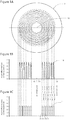
Figure 1A is a frontal view of a 7-zone concentric multi-zone multi-defocusing contact lens in accordance with an embodiment of the present invention; -
Figure 1B shows a desirable power profile across the lens in accordance with an embodiment of the present invention; -
Figure 1C shows a less desirable power profile across a concentric multi-zone lens of the prior art; -
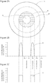
Figure 2A is a frontal view of a 3-zone concentric multi-zone contact lens in accordance with an embodiment of the present invention; -
Figure 2B shows a desirable power profile across the lens in accordance with an embodiment of the present invention; -
Figure 2C shows a less desirable power profile across a concentric multi-zone lens of the prior art; -
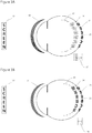
Figure 3A is a diagram of a myopic eye fitted with a concentric multi-zone multi- defocusing lens in accordance with an embodiment of the present invention; and -
Figure 3B is a diagram of a myopic eye fitted with a concentric multi-zone bifocal lens of the prior art; -
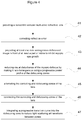
Figure 4 is a process flow diagram of a method for retarding the progression of myopia in a human eye in accordance with a preferred embodiment of the present invention. - Two examples for retarding progression of myopia in human eyes are described. The apparatuses used to practice this method alter the defocus equilibrium of the eye to influence dimensional eye growth in a direction towards emmetropia. In particular, myopic defocus is induced in the eye to retard the progression of myopia.
- The myopic defocus can be introduced by various ways and apparatuses, for example, by spectacle lens, spectacle lens add-on, contact lens, corneal or intraocular implant. It is important that myopic defocus is introduced when normal vision is maintained throughout the treatment. That means that a focused homogenous image must be maintained at the central retina during the treatment.
- A concentric bifocal lens splits incoming light rays and focuses them into two images. Therefore, it is an effective means for simultaneously providing clear vision and myopic defocus. An important next step is to reduce undesirable visual disturbance caused by the homogenous defocused image overlapping on the focused retina image while achieving optimal retarding effect.
- A treatment method is provided to introduce multiple defocused images in front of the retina and a single homogeneous focused image on the retina. This is achieved using a concentric multi-zone multifocal lens having a characteristic partial sinusoidal power profile.
- Referring to
Figure 1A , a 13-zone contact lens 9 is provided as a concentric multi- zone multifocal lens having a characteristic partial sinusoidal power profile. There are seven correcting zones and six defocusing zones alternating in a concentric manner. This number of alternating zones allows a reasonably stable area ratio between the two zones to be maintained under a range of pupil sizes and lighting conditions. Therefore stable clear vision and retarding effectiveness can be maintained in different lighting conditions. A central correctingzone 12 has a diameter of 2.8mm, which is smaller than the typical pupil size of children and young adults (4.0-5.0mm). Therefore, a few consecutive annular defocusing and correcting zones always overlies on the pupil and introduce a defocused image on the retina including the central on-axis region. The width of each annular zone of alternating functions is 0.3mm. All seven correcting zones share the same power to neutralize the pre-existing myopia (for example, distance prescription) of a wearer. For example, if the wearer has 3D of myopia, the power of the correcting zone may be -3D. The homogenous power profile in the correcting zones ensure that the image formed is homogenous and of high optical quality for good vision. On the other hand, each of the six defocusing zones comprises a range of less negative powers. The progressive (specifically sinusoidal)power profile 10 of the defocusing zones does not introduce a homogenous secondary defocused image but non- homogenous multiple defocused images that are slightly separated from each others and of lower intensity. This is in contrast to asquare power profile 11 of the lens of the prior art, - The 5D power differences between correcting zones and defocusing zones ensure that the defocus generated is potent enough to achieve optimal retarding effect. For example the power of each of the defocusing zone ranges between -3 to and 2D to introduce myopic defocus, if the wearer has 3D of myopia. An extra benefit from the sinusoidal power profile of the defocusing zones is that the transitions between adjacent curves become progressive and do not create undesirable diffraction as created by the
sudden power change 13 in the square power profile of prior art designs. A progressive transition curve occurs where the power change across adjacent zone is continuous. There are many possible shapes not covered by the invention which can be regarded as progressive transition including but not limited to: sigmoidal, polynomial, conical, parabolic. In the described embodiment, the method is described using a partial sinusoidal shape for the overall power profile of the lens. - The edge of the lens 9 is made of a non-optical zone for lens stabilization purpose. The total diameter of the lens 9 in the example is 13.6mm. It is preferred that the alternating sinusoidal power profile be achieved by manipulating the radius of curvature of the anterior surface of the lens 9, and leaving the posterior surface for toric manipulations to correct astigmatism.
- In
Figure 1B , the power profile of each defocusing zone is progressive and is like a sinusoidal pattern. In contrast, inFigure 1C , the prior art shows that the power profile of each defocusing zone is homogenous, and that this square power profile
of the lens causes asudden power change 13. - Referring to
Figure 2A , a 3-zone contact lens 19 is provided as a concentric multi- zone multifocal lens having a characteristic partial sinusoidal power profile. There are two correcting zones and one defocusing zone alternating in a concentric manner. This number of alternating zones reduces manufacturing complexity yet still provides capability to introduce non-homogenous multiple defocused images covering the entire retina. - The central correcting
zone 22 has a diameter of 3mm, which is smaller than the typical pupil size of children and young adults (4.0mm to 5.0mm). Therefore, the immediate surrounding annularfirst defocusing zone 23 always overlies with the pupil, introducing a defocused image on the retina (including the central on-axis region of the retina). The defocusingzone 23 has an annular width of 1.5mm and is surrounding by a second correctingzone 24 having an annular width of 2.0mm. Again, both of the two correctingzones zones zones zone 23 comprises a range of less negative powers. - Referring to
Figure 2B , the sinusoidal power profiles 20 of the defocusing zone introduces multiple defocused images that are slightly separated from each others and of lower intensity as shown inFigure 3A . The 6D power differences between correcting zones and defocusing zones ensure that defocus generated is potent enough to achieve optimal retarding effect. For example, the power of each of the defocusing zones ranges between -4 to +2D to introduce myopic defocus, if the wearer has 4D of myopia. The edge of the lens is made of a non-optic zone for lens stabilization purpose. The total lens diameter in this example is 13.6mm. - Referring to
Figure 2B , thesquare power profile 21 of the prior art introduces a homogenous secondary defocused image. Furthermore, the prior art does not integrate any progressive transition curve as part of the power profile. Thus the power change across adjacent zones is non-continuous, abrupt, sudden, and stepwise. - In
Figure 2B , the power profile of the defocusing zone is progressive and is like a sinusoidal pattern. In contrast, inFigure 2C , the prior art shows the power profile of each defocusing zone is homogenous. - In
Figures 3A and 3B , a homogeneousfocused image common object 32 is formed on theretina 29 to provide good vision. - Turning to
Figure 3A , a myopic eye fitted with a concentric multi-zone multi- defocusinglens 30 has a partial sinusoidal power profile. The multiple non homogeneousdefocused images 34 produced by the presentmulti-defocusing lens 30 are non-homogeneous and are dim compared to thefocused image 33 on theretina 29. Therefore, it does not serve as a significant source of visual disturbance while a therapeutic range ofmyopic defocus 37 may be maintained across theretina 29. - A
common object 32 is projected as a homogenousfocused image 33 on theretina 29, and as multiple non homogeneousdefocused images 34 in front of theretina 29. A range ofdefocus 37 is induced over theretina 29 both axially and peripherally as thefocal planes 39 extend across theentire retina 29. - Referring to
Figure 3B , a myopic eye fitted with a prior art concentric multi-zonebifocal lens 31 has a square power profile. The secondarydefocused image 36 produced by thebifocal lens 31 is quite homogeneous compared to the homogenousfocused image 35 onretina 29. Although a therapeutic dose ofmyopic defocus 38 is maintained across theretina 29, the homogeneousdefocused image 36 serves as a source of visual disturbance. - A
common object 32 is projected as a homogenousfocused image 35 on theretina 29, and as another homogenousdefocused image 36 in front of theretina 29. A homogeneous magnitude ofdefocus 38 is induced in front of theretina 29 both axially and peripherally as thefocal plane 28 extends across theentire retina 29. - Referring to
Figure 4 , the method described retards the progression of myopia in a human eye. A concentric annular multi-zone refractive lens is provided (41). The lens has at least one correcting zone of optical power for correcting (42) refractive error. When the refractive error is corrected by the correcting zone, clear vision is provided for objects at all distances and natural ocular accommodation is used for near tasks. - The lens also has at least one defocusing zone for projecting (43) at least one non-homogenous defocused image in front of at least a part of retina to inhibit myopic eye growth. A non-homogenous myopic defocus is introduced on the retina using the defocusing zones at all times regardless of viewing distance. The at least one defocusing zone has at least one less negative power. The visual disturbance of the myopic defocus is reduced (44) by making it non-homogenous using a progressive power profile of the defocusing zones. By making the defocused image non-homogenous, misuse of the defocusing zones for viewing is avoided. Also, the non-homogenous myopic defocus inhibits eye growth. The correcting and defocusing zones are alternated (45) in the lens. The correcting and defocusing zones are connected (46) to each other through integrated progressive transition curves. This improves optical performance by reducing (47) light scattering at transitions between zones.
- Although particular applications in curing and retarding the progression of refractive disorder of the eye have been described, it is envisaged that the present invention may be used in other applications such as preventing pathological myopic degeneration of the eye.
- It will be appreciated by persons skilled in the art that numerous variations and/or modifications may be made to the invention as shown in the specific embodiments without departing from the scope of the invention as broadly described. The present embodiments are, therefore, to be considered in all respects illustrative and not restrictive.
Claims (19)
- A refractive lens (9) for retarding the progression of myopia in a human eye, the refractive lens (9) comprising:a concentric annular multi-zone refractive lens including:correcting zones (12, 22, 24) of optical power for correcting refractive error, anddefocusing zones (23) having a progressive power profile (10) for projecting multiple defocus images or non-homogenous defocused images in front of at least a part of retina to inhibit myopic eye growth, the defocusing zones (23) having a range of less negative powers than the optical power for correcting refractive power of the correcting zones (12, 22, 24);wherein the correcting zones (12, 22, 24) and the defocusing zones (23) are alternated in the lens,wherein the lens has at least a total number of more than three correcting zones (12, 22, 24) and defocusing zones (23) alternating in a concentric manner,wherein the central first correcting/defocusing zone (12, 22, 23, 24) is smaller than the pupil is measured under photopic lighting conditions,wherein the same single homogeneous power is maintained over the correcting zones (12, 22, 24),characterized in that the defocusing zones have a sinusoidal power profile.
- The refractive lens (9) according to claim 1, wherein the lens is in the form of a refractive lens and its optical surface includes 4 to 40 alternating correcting and defocusing zones (23).
- The refractive lens (9) according to claim 2, wherein the lens has a central zone that is a circular first correcting zone (12, 22, 24) having a diameter smaller than the pupil of the eye under photopic lighting.
- The refractive lens (9) according to claim 3, wherein the first correcting zone (12, 22, 24) is immediately surrounded by a first defocusing zone (23) having an annular shape.
- The refractive lens (9) according to claim 4, wherein the first defocusing zone (23) is immediately surrounded by a second correcting zone (12, 22, 24) having an annular shape.
- The refractive lens (9) according to claim 5, wherein the second correcting zone (12, 22) is surrounded by additional defocusing zones (23) and correcting zones (12, 22, 24) in an alternating manner.
- The refractive lens (9) according to claim 2, wherein the lens has a central zone that is a circular first defocusing zone (23) having a diameter smaller than the pupil of the eye under photopic lighting.
- The refractive lens (9) according to claim 7, wherein the first defocusing zone (23) is immediately surrounded by a first correcting zone (12, 22, 24) having an annular shape.
- The refractive lens (9) according to claim 8, wherein the first correcting zone (12, 22, 24) is immediately surrounded by a second defocusing zone (23) having an annular shape.
- The refractive lens (9) according to claim 9, wherein the second defocusing zone (23) is surrounded by additional defocusing zones (23) and correcting zones (12, 22, 24) in an alternating manner.
- The refractive lens (9) according to claim 1, wherein the maximal difference between the power of the correcting zones (12, 22, 24) and the peak power of the defocusing zones (23) is between about 0.5 to 10.0 diopters.
- The refractive lens (9) according to claim 3 or 7, wherein the diameter of the central zone is about 2.0mm to 4.5mm.
- The refractive lens (9) according to claim 11, wherein at least part of the defocusing zones (23) and at least a part of the correcting zone (12, 22, 24) overlies the pupil at the same time.
- The refractive lens (9) according to claim 1, wherein the power profile of the defocusing zones (23) is progressive causing transitions between adjacent curves to become progressive.
- The refractive lens (9) according to claim 1, wherein the progressive power profile (10) is generated by adjusting the radius of curvature of the anterior refractive surface of the lens or by adjusting the posterior curvature or the refractive index of the lens.
- The refractive lens (9) according to claim 1, further comprising an integrated progressive transition curve between adjacent zones of the lens.
- The refractive lens (9) according to claim 1, wherein the lens has seven correcting zones (12, 22, 24) and six defocusing zones (23) to maintain a relatively stable area ratio between the correcting zones (12, 22, 24) and defocusing zones (23) for a range of pupil sizes and lighting conditions.
- The refractive lens (9) according to claim 1, wherein the multiple defocus images or the non-homogenous defocused images projected by the defocusing zones (23) have a lower intensity than a retinal images projected by the correcting zones (12, 22, 24).
- The refractive lens (9) according to claim 1, wherein the correcting zones (12, 22, 24) of the lens project focused images onto the retina for visual objects positioned at all distances.
Priority Applications (1)
| Application Number | Priority Date | Filing Date | Title |
|---|---|---|---|
| EP21180977.7A EP3929653A1 (en) | 2010-09-13 | 2010-09-13 | A method and system for retarding the progression of myopia |
Applications Claiming Priority (1)
| Application Number | Priority Date | Filing Date | Title |
|---|---|---|---|
| PCT/CN2010/076839 WO2012034265A1 (en) | 2010-09-13 | 2010-09-13 | Method and system for retarding progression of myopia |
Related Child Applications (1)
| Application Number | Title | Priority Date | Filing Date |
|---|---|---|---|
| EP21180977.7A Division EP3929653A1 (en) | 2010-09-13 | 2010-09-13 | A method and system for retarding the progression of myopia |
Publications (3)
| Publication Number | Publication Date |
|---|---|
| EP2616876A1 EP2616876A1 (en) | 2013-07-24 |
| EP2616876A4 EP2616876A4 (en) | 2015-04-01 |
| EP2616876B1 true EP2616876B1 (en) | 2021-06-23 |
Family
ID=45830916
Family Applications (2)
| Application Number | Title | Priority Date | Filing Date |
|---|---|---|---|
| EP21180977.7A Pending EP3929653A1 (en) | 2010-09-13 | 2010-09-13 | A method and system for retarding the progression of myopia |
| EP10857121.7A Revoked EP2616876B1 (en) | 2010-09-13 | 2010-09-13 | System for retarding progression of myopia |
Family Applications Before (1)
| Application Number | Title | Priority Date | Filing Date |
|---|---|---|---|
| EP21180977.7A Pending EP3929653A1 (en) | 2010-09-13 | 2010-09-13 | A method and system for retarding the progression of myopia |
Country Status (4)
| Country | Link |
|---|---|
| EP (2) | EP3929653A1 (en) |
| JP (1) | JP2013537317A (en) |
| CN (1) | CN103097940B (en) |
| WO (1) | WO2012034265A1 (en) |
Cited By (1)
| Publication number | Priority date | Publication date | Assignee | Title |
|---|---|---|---|---|
| EP4379456A4 (en) * | 2021-07-28 | 2025-08-20 | Univ Hong Kong Polytechnic | Ring focus lens for controlling the progression of myopia and manufacturing method therefor |
Families Citing this family (53)
| Publication number | Priority date | Publication date | Assignee | Title |
|---|---|---|---|---|
| EP3552587A1 (en) | 2008-12-22 | 2019-10-16 | Medical College of Wisconsin, Inc. | Method and apparatus for limiting growth of eye length |
| JP5747279B2 (en) * | 2011-04-28 | 2015-07-15 | 東海光学株式会社 | Design method for vision correction lens |
| TWI588560B (en) | 2012-04-05 | 2017-06-21 | 布萊恩荷登視覺協會 | Lens, device, method and system for refractive error |
| US9201250B2 (en) | 2012-10-17 | 2015-12-01 | Brien Holden Vision Institute | Lenses, devices, methods and systems for refractive error |
| HUE066245T2 (en) * | 2012-10-17 | 2024-07-28 | Holden Brien Vision Inst | Lenses, devices, methods and systems for treating refractive errors |
| WO2014184399A1 (en) * | 2013-05-15 | 2014-11-20 | Tiedra Farmacéutica, S.L. | Myopia-correcting/-stabilising soft contact lens |
| US9638936B2 (en) | 2014-08-20 | 2017-05-02 | Johnson & Johnson Vision Care, Inc. | High plus treatment zone lens design for preventing and/or slowing myopia progression |
| US20170115509A1 (en) * | 2014-08-20 | 2017-04-27 | Johnson & Johnson Vision Care, Inc. | High plus center treatment zone lens design and method for preventing and/or slowing myopia progression |
| US9977257B2 (en) * | 2016-03-22 | 2018-05-22 | Johnson & Johnson Vision Care, Inc. | Multifocal lens design and method for preventing and/or slowing myopia progression |
| SG11201900867UA (en) | 2016-08-01 | 2019-02-27 | Jay Neitz | Ophthalmic lenses for treating myopia |
| WO2018195600A1 (en) * | 2017-04-28 | 2018-11-01 | Brien Holden Vision Institute | Systems, methods and devices for controlling the progression of myopia |
| TWI685692B (en) | 2017-05-08 | 2020-02-21 | 美商賽特眼鏡視光有限公司 | Contact lenses for reducing myopia and methods for making the same |
| CN109116576A (en) * | 2017-06-23 | 2019-01-01 | 星欧光学股份有限公司 | Contact lenses and products thereof |
| US10698232B2 (en) | 2017-06-23 | 2020-06-30 | Largan Medical Co., Ltd. | Contact lens and product thereof |
| WO2019114463A1 (en) * | 2017-12-11 | 2019-06-20 | The Hong Kong Polytechnic University | Methods, devices, and systems for inhibiting ocular refractive disorders from progressing |
| US11768386B2 (en) | 2018-01-22 | 2023-09-26 | Johnson & Johnson Vision Care, Inc. | Ophthalmic lens with an optically non-coaxial zone for myopia control |
| US10901237B2 (en) * | 2018-01-22 | 2021-01-26 | Johnson & Johnson Vision Care, Inc. | Ophthalmic lens with an optically non-coaxial zone for myopia control |
| US11789292B2 (en) | 2018-01-22 | 2023-10-17 | Johnson & Johnson Vision Care, Inc. | Ophthalmic lens with an optically non-coaxial zone for myopia control |
| US10884264B2 (en) | 2018-01-30 | 2021-01-05 | Sightglass Vision, Inc. | Ophthalmic lenses with light scattering for treating myopia |
| BR112020017312B1 (en) | 2018-03-01 | 2023-03-14 | Essilor International | LENS ELEMENT |
| KR102797221B1 (en) * | 2018-04-26 | 2025-04-18 | 에씰로 앙터나시오날 | Lens elements |
| EP3821291A4 (en) | 2018-07-12 | 2022-04-13 | Sightglass Vision, Inc. | Methods and devices for reducing myopia in children |
| US12416818B2 (en) | 2019-03-01 | 2025-09-16 | Sightglass Vision, Inc. | Ophthalmic lenses for reducing myopic progression and methods of making the same |
| US12357509B2 (en) | 2019-04-05 | 2025-07-15 | Amo Groningen B.V. | Systems and methods for improving vision from an intraocular lens in an incorrect position and using refractive index writing |
| US12377622B2 (en) | 2019-04-05 | 2025-08-05 | Amo Groningen B.V. | Systems and methods for vergence matching with an optical profile and using refractive index writing |
| US11944574B2 (en) | 2019-04-05 | 2024-04-02 | Amo Groningen B.V. | Systems and methods for multiple layer intraocular lens and using refractive index writing |
| US11583388B2 (en) | 2019-04-05 | 2023-02-21 | Amo Groningen B.V. | Systems and methods for spectacle independence using refractive index writing with an intraocular lens |
| US11529230B2 (en) | 2019-04-05 | 2022-12-20 | Amo Groningen B.V. | Systems and methods for correcting power of an intraocular lens using refractive index writing |
| US11583389B2 (en) | 2019-04-05 | 2023-02-21 | Amo Groningen B.V. | Systems and methods for correcting photic phenomenon from an intraocular lens and using refractive index writing |
| US11564839B2 (en) | 2019-04-05 | 2023-01-31 | Amo Groningen B.V. | Systems and methods for vergence matching of an intraocular lens with refractive index writing |
| US11678975B2 (en) | 2019-04-05 | 2023-06-20 | Amo Groningen B.V. | Systems and methods for treating ocular disease with an intraocular lens and refractive index writing |
| US12111518B2 (en) | 2019-04-23 | 2024-10-08 | Sightglass Vision, Inc. | Ophthalmic lenses with dynamic optical properties for reducing development of myopia |
| CN111830731B (en) * | 2019-04-23 | 2021-12-17 | 刘梁 | Spectacle lens for preventing and slowing down development of myopia |
| JP7657519B2 (en) * | 2019-06-25 | 2025-04-07 | ホヤ レンズ タイランド リミテッド | Eyeglass lenses and design methods thereof |
| CN114391121B (en) * | 2019-09-12 | 2024-03-26 | 香港理工大学 | Lenses and methods for slowing progression of myopia |
| US20220342233A1 (en) * | 2019-09-19 | 2022-10-27 | The Uab Research Foundation | Multi-spectral and multi-focal control of myopia |
| US12271057B1 (en) * | 2019-12-20 | 2025-04-08 | The Uab Research Foundation | Chromatic aberration tuning ophthalmic corrector lens methods |
| EP4324631A3 (en) * | 2020-03-31 | 2024-03-27 | Essilor International | Lens element |
| GB2584546B (en) * | 2020-04-06 | 2021-09-01 | Novasight Ltd | Method and device for treating vision impairment |
| JP7541882B2 (en) * | 2020-09-18 | 2024-08-29 | ホヤ レンズ タイランド リミテッド | Eyeglass lenses and their design method |
| US12019311B2 (en) * | 2020-11-04 | 2024-06-25 | Bausch & Lomb Ireland Limited | Ophthalmic lens including a peripheral zone having an add-power offset and a spatially-modulated optical parameter |
| TWI741902B (en) * | 2020-12-07 | 2021-10-01 | 春秋光學股份有限公司 | Lenses used to slow down or prevent the progression of myopia |
| TWI763344B (en) * | 2021-03-03 | 2022-05-01 | 永勝光學股份有限公司 | Contact Lenses |
| CN115032813B (en) * | 2021-03-03 | 2024-07-12 | 永胜光学股份有限公司 | Contact lens |
| CN113267904B (en) * | 2021-06-02 | 2025-02-14 | 欧普康视科技股份有限公司 | A method for designing the optical zone of multifocal soft contact lenses |
| EP4163705A1 (en) | 2021-10-05 | 2023-04-12 | Essilor International | Lens element with improved visual performance |
| EP4163706A1 (en) | 2021-10-05 | 2023-04-12 | Essilor International | Lens element |
| KR20250002113A (en) | 2022-04-21 | 2025-01-07 | 에씰로 앙터나시오날 | Lenses with improved visual performance |
| CN114967179A (en) * | 2022-06-22 | 2022-08-30 | 珠海博爱之光科技有限公司 | Spectacle structure, contact lens and spectacle |
| CN115167008B (en) * | 2022-08-15 | 2025-07-29 | 上海艾康特医疗科技有限公司 | Optical lens |
| CN115494658A (en) * | 2022-09-21 | 2022-12-20 | 珠海博爱之光科技有限公司 | Soft contact lens |
| EP4642626A1 (en) * | 2022-12-29 | 2025-11-05 | Sightglass Vision, Inc. | Ophthalmic lenses with optical scattering region |
| CN116400518B (en) * | 2023-03-27 | 2024-01-05 | 温州明辉视光科技有限公司 | Lens structure |
Citations (12)
| Publication number | Priority date | Publication date | Assignee | Title |
|---|---|---|---|---|
| US4890913A (en) | 1982-10-13 | 1990-01-02 | Carle John T De | Zoned multi-focal contact lens |
| WO1991009336A1 (en) | 1989-12-07 | 1991-06-27 | Leonard Seidner | Corneal contact lenses |
| CA1326389C (en) | 1987-06-01 | 1994-01-25 | Valdemar Portney | Multifocal ophthalmic lens |
| US5835192A (en) | 1995-12-21 | 1998-11-10 | Johnson & Johnson Vision Products, Inc. | Contact lenses and method of fitting contact lenses |
| US6030077A (en) | 1998-03-11 | 2000-02-29 | Menicon Co., Ltd. | Multifocal ocular lens having intermediate region with continuously varying optical power |
| US6045578A (en) | 1995-11-28 | 2000-04-04 | Queensland University Of Technology | Optical treatment method |
| US20050068494A1 (en) | 2000-09-08 | 2005-03-31 | Griffin Richard A. | Ophthalmic lenses with induced aperture and redundant power regions |
| WO2006034652A1 (en) | 2004-09-30 | 2006-04-06 | The Hong Kong Polytechnic University | Method of optical treatment |
| WO2007041796A1 (en) | 2005-10-12 | 2007-04-19 | Carl Zeiss Vision Australia Holdings Limited | Ophthalmic lens element for myopia correction |
| EP1967892A1 (en) | 2007-03-09 | 2008-09-10 | Auckland Uniservices Limited | Contact lens and method of preventing or slowing myopia progression |
| US20100036489A1 (en) | 2008-08-11 | 2010-02-11 | Joseph Michael Lindacher | Lens design and method for preventing or slowing the progression of myopia |
| US20100085536A1 (en) | 2008-10-07 | 2010-04-08 | Essilor International (Compagnie Generale D'optique) | Ophthalmic Eyeglass Correcting Both Foveal Vision and Peripheral Vision |
Family Cites Families (9)
| Publication number | Priority date | Publication date | Assignee | Title |
|---|---|---|---|---|
| US5112351A (en) * | 1990-10-12 | 1992-05-12 | Ioptex Research Inc. | Multifocal intraocular lenses |
| GB2295686B (en) * | 1994-11-30 | 1998-05-06 | Carle John Trevor De | Bifocal contact lenses |
| EP0822439A4 (en) * | 1996-02-21 | 2007-01-31 | Seiko Epson Corp | PROGRESSIVE HOME CONTACT LENSES |
| US6536899B1 (en) * | 1999-07-14 | 2003-03-25 | Bifocon Optics Gmbh | Multifocal lens exhibiting diffractive and refractive powers |
| US6752499B2 (en) * | 2001-07-11 | 2004-06-22 | Thomas A. Aller | Myopia progression control using bifocal contact lenses |
| EP1691741B1 (en) | 2003-11-19 | 2009-12-23 | Vision Crc Limited | Apparatuses for altering relative curvature of field and positions of peripheral, off-axis focal positions |
| US8240847B2 (en) * | 2006-06-08 | 2012-08-14 | Vision Crc Limited | Means for controlling the progression of myopia |
| US7637612B2 (en) * | 2007-05-21 | 2009-12-29 | Johnson & Johnson Vision Care, Inc. | Ophthalmic lenses for prevention of myopia progression |
| CA2761855C (en) * | 2009-10-22 | 2019-11-12 | Coopervision International Holding Company, Lp | Contact lens sets and methods to prevent or slow progression of myopia or hyperopia |
-
2010
- 2010-09-13 WO PCT/CN2010/076839 patent/WO2012034265A1/en not_active Ceased
- 2010-09-13 EP EP21180977.7A patent/EP3929653A1/en active Pending
- 2010-09-13 EP EP10857121.7A patent/EP2616876B1/en not_active Revoked
- 2010-09-13 JP JP2013527440A patent/JP2013537317A/en active Pending
- 2010-09-13 CN CN201080069081.0A patent/CN103097940B/en active Active
Patent Citations (12)
| Publication number | Priority date | Publication date | Assignee | Title |
|---|---|---|---|---|
| US4890913A (en) | 1982-10-13 | 1990-01-02 | Carle John T De | Zoned multi-focal contact lens |
| CA1326389C (en) | 1987-06-01 | 1994-01-25 | Valdemar Portney | Multifocal ophthalmic lens |
| WO1991009336A1 (en) | 1989-12-07 | 1991-06-27 | Leonard Seidner | Corneal contact lenses |
| US6045578A (en) | 1995-11-28 | 2000-04-04 | Queensland University Of Technology | Optical treatment method |
| US5835192A (en) | 1995-12-21 | 1998-11-10 | Johnson & Johnson Vision Products, Inc. | Contact lenses and method of fitting contact lenses |
| US6030077A (en) | 1998-03-11 | 2000-02-29 | Menicon Co., Ltd. | Multifocal ocular lens having intermediate region with continuously varying optical power |
| US20050068494A1 (en) | 2000-09-08 | 2005-03-31 | Griffin Richard A. | Ophthalmic lenses with induced aperture and redundant power regions |
| WO2006034652A1 (en) | 2004-09-30 | 2006-04-06 | The Hong Kong Polytechnic University | Method of optical treatment |
| WO2007041796A1 (en) | 2005-10-12 | 2007-04-19 | Carl Zeiss Vision Australia Holdings Limited | Ophthalmic lens element for myopia correction |
| EP1967892A1 (en) | 2007-03-09 | 2008-09-10 | Auckland Uniservices Limited | Contact lens and method of preventing or slowing myopia progression |
| US20100036489A1 (en) | 2008-08-11 | 2010-02-11 | Joseph Michael Lindacher | Lens design and method for preventing or slowing the progression of myopia |
| US20100085536A1 (en) | 2008-10-07 | 2010-04-08 | Essilor International (Compagnie Generale D'optique) | Ophthalmic Eyeglass Correcting Both Foveal Vision and Peripheral Vision |
Cited By (1)
| Publication number | Priority date | Publication date | Assignee | Title |
|---|---|---|---|---|
| EP4379456A4 (en) * | 2021-07-28 | 2025-08-20 | Univ Hong Kong Polytechnic | Ring focus lens for controlling the progression of myopia and manufacturing method therefor |
Also Published As
| Publication number | Publication date |
|---|---|
| EP2616876A4 (en) | 2015-04-01 |
| CN103097940B (en) | 2016-02-03 |
| EP2616876A1 (en) | 2013-07-24 |
| WO2012034265A1 (en) | 2012-03-22 |
| CN103097940A (en) | 2013-05-08 |
| EP3929653A1 (en) | 2021-12-29 |
| JP2013537317A (en) | 2013-09-30 |
Similar Documents
| Publication | Publication Date | Title |
|---|---|---|
| EP2616876B1 (en) | System for retarding progression of myopia | |
| US9829722B2 (en) | Method and system for retarding the progression of myopia | |
| US12271059B2 (en) | Contact lenses for myopic eyes and methods of treating myopia | |
| EP2537062B1 (en) | Corneal remodelling contact lenses and methods of treating refractive error using corneal remodelling | |
| CN218524972U (en) | Ophthalmic lenses and spectacles with same | |
| HK1176686B (en) | Corneal remodelling contact lenses | |
| HK1209493B (en) | Contact lenses for myopic eyes and methods of treating myopia | |
| HK1176124B (en) | Contact lenses for myopic eyes and methods of treating myopia |
Legal Events
| Date | Code | Title | Description |
|---|---|---|---|
| PUAI | Public reference made under article 153(3) epc to a published international application that has entered the european phase |
Free format text: ORIGINAL CODE: 0009012 |
|
| 17P | Request for examination filed |
Effective date: 20130415 |
|
| AK | Designated contracting states |
Kind code of ref document: A1 Designated state(s): AL AT BE BG CH CY CZ DE DK EE ES FI FR GB GR HR HU IE IS IT LI LT LU LV MC MK MT NL NO PL PT RO SE SI SK SM TR |
|
| DAX | Request for extension of the european patent (deleted) | ||
| A4 | Supplementary search report drawn up and despatched |
Effective date: 20150227 |
|
| RIC1 | Information provided on ipc code assigned before grant |
Ipc: G02C 7/04 20060101AFI20150223BHEP Ipc: A61F 9/00 20060101ALI20150223BHEP Ipc: G02C 7/06 20060101ALI20150223BHEP Ipc: A61F 2/14 20060101ALI20150223BHEP |
|
| STAA | Information on the status of an ep patent application or granted ep patent |
Free format text: STATUS: EXAMINATION IS IN PROGRESS |
|
| 17Q | First examination report despatched |
Effective date: 20170309 |
|
| GRAP | Despatch of communication of intention to grant a patent |
Free format text: ORIGINAL CODE: EPIDOSNIGR1 |
|
| STAA | Information on the status of an ep patent application or granted ep patent |
Free format text: STATUS: GRANT OF PATENT IS INTENDED |
|
| INTG | Intention to grant announced |
Effective date: 20190104 |
|
| GRAJ | Information related to disapproval of communication of intention to grant by the applicant or resumption of examination proceedings by the epo deleted |
Free format text: ORIGINAL CODE: EPIDOSDIGR1 |
|
| STAA | Information on the status of an ep patent application or granted ep patent |
Free format text: STATUS: EXAMINATION IS IN PROGRESS |
|
| INTC | Intention to grant announced (deleted) | ||
| TPAC | Observations filed by third parties |
Free format text: ORIGINAL CODE: EPIDOSNTIPA |
|
| GRAP | Despatch of communication of intention to grant a patent |
Free format text: ORIGINAL CODE: EPIDOSNIGR1 |
|
| STAA | Information on the status of an ep patent application or granted ep patent |
Free format text: STATUS: GRANT OF PATENT IS INTENDED |
|
| INTG | Intention to grant announced |
Effective date: 20210301 |
|
| GRAS | Grant fee paid |
Free format text: ORIGINAL CODE: EPIDOSNIGR3 |
|
| GRAA | (expected) grant |
Free format text: ORIGINAL CODE: 0009210 |
|
| STAA | Information on the status of an ep patent application or granted ep patent |
Free format text: STATUS: THE PATENT HAS BEEN GRANTED |
|
| AK | Designated contracting states |
Kind code of ref document: B1 Designated state(s): AL AT BE BG CH CY CZ DE DK EE ES FI FR GB GR HR HU IE IS IT LI LT LU LV MC MK MT NL NO PL PT RO SE SI SK SM TR |
|
| REG | Reference to a national code |
Ref country code: GB Ref legal event code: FG4D |
|
| REG | Reference to a national code |
Ref country code: CH Ref legal event code: EP |
|
| REG | Reference to a national code |
Ref country code: DE Ref legal event code: R096 Ref document number: 602010067173 Country of ref document: DE Ref country code: AT Ref legal event code: REF Ref document number: 1404797 Country of ref document: AT Kind code of ref document: T Effective date: 20210715 |
|
| REG | Reference to a national code |
Ref country code: IE Ref legal event code: FG4D |
|
| REG | Reference to a national code |
Ref country code: LT Ref legal event code: MG9D |
|
| PG25 | Lapsed in a contracting state [announced via postgrant information from national office to epo] |
Ref country code: FI Free format text: LAPSE BECAUSE OF FAILURE TO SUBMIT A TRANSLATION OF THE DESCRIPTION OR TO PAY THE FEE WITHIN THE PRESCRIBED TIME-LIMIT Effective date: 20210623 Ref country code: LT Free format text: LAPSE BECAUSE OF FAILURE TO SUBMIT A TRANSLATION OF THE DESCRIPTION OR TO PAY THE FEE WITHIN THE PRESCRIBED TIME-LIMIT Effective date: 20210623 Ref country code: BG Free format text: LAPSE BECAUSE OF FAILURE TO SUBMIT A TRANSLATION OF THE DESCRIPTION OR TO PAY THE FEE WITHIN THE PRESCRIBED TIME-LIMIT Effective date: 20210923 Ref country code: HR Free format text: LAPSE BECAUSE OF FAILURE TO SUBMIT A TRANSLATION OF THE DESCRIPTION OR TO PAY THE FEE WITHIN THE PRESCRIBED TIME-LIMIT Effective date: 20210623 |
|
| REG | Reference to a national code |
Ref country code: AT Ref legal event code: MK05 Ref document number: 1404797 Country of ref document: AT Kind code of ref document: T Effective date: 20210623 |
|
| PG25 | Lapsed in a contracting state [announced via postgrant information from national office to epo] |
Ref country code: NO Free format text: LAPSE BECAUSE OF FAILURE TO SUBMIT A TRANSLATION OF THE DESCRIPTION OR TO PAY THE FEE WITHIN THE PRESCRIBED TIME-LIMIT Effective date: 20210923 Ref country code: GR Free format text: LAPSE BECAUSE OF FAILURE TO SUBMIT A TRANSLATION OF THE DESCRIPTION OR TO PAY THE FEE WITHIN THE PRESCRIBED TIME-LIMIT Effective date: 20210924 Ref country code: LV Free format text: LAPSE BECAUSE OF FAILURE TO SUBMIT A TRANSLATION OF THE DESCRIPTION OR TO PAY THE FEE WITHIN THE PRESCRIBED TIME-LIMIT Effective date: 20210623 Ref country code: SE Free format text: LAPSE BECAUSE OF FAILURE TO SUBMIT A TRANSLATION OF THE DESCRIPTION OR TO PAY THE FEE WITHIN THE PRESCRIBED TIME-LIMIT Effective date: 20210623 |
|
| REG | Reference to a national code |
Ref country code: NL Ref legal event code: MP Effective date: 20210623 |
|
| PG25 | Lapsed in a contracting state [announced via postgrant information from national office to epo] |
Ref country code: CZ Free format text: LAPSE BECAUSE OF FAILURE TO SUBMIT A TRANSLATION OF THE DESCRIPTION OR TO PAY THE FEE WITHIN THE PRESCRIBED TIME-LIMIT Effective date: 20210623 Ref country code: EE Free format text: LAPSE BECAUSE OF FAILURE TO SUBMIT A TRANSLATION OF THE DESCRIPTION OR TO PAY THE FEE WITHIN THE PRESCRIBED TIME-LIMIT Effective date: 20210623 Ref country code: SM Free format text: LAPSE BECAUSE OF FAILURE TO SUBMIT A TRANSLATION OF THE DESCRIPTION OR TO PAY THE FEE WITHIN THE PRESCRIBED TIME-LIMIT Effective date: 20210623 Ref country code: SK Free format text: LAPSE BECAUSE OF FAILURE TO SUBMIT A TRANSLATION OF THE DESCRIPTION OR TO PAY THE FEE WITHIN THE PRESCRIBED TIME-LIMIT Effective date: 20210623 Ref country code: AT Free format text: LAPSE BECAUSE OF FAILURE TO SUBMIT A TRANSLATION OF THE DESCRIPTION OR TO PAY THE FEE WITHIN THE PRESCRIBED TIME-LIMIT Effective date: 20210623 Ref country code: RO Free format text: LAPSE BECAUSE OF FAILURE TO SUBMIT A TRANSLATION OF THE DESCRIPTION OR TO PAY THE FEE WITHIN THE PRESCRIBED TIME-LIMIT Effective date: 20210623 Ref country code: NL Free format text: LAPSE BECAUSE OF FAILURE TO SUBMIT A TRANSLATION OF THE DESCRIPTION OR TO PAY THE FEE WITHIN THE PRESCRIBED TIME-LIMIT Effective date: 20210623 Ref country code: PT Free format text: LAPSE BECAUSE OF FAILURE TO SUBMIT A TRANSLATION OF THE DESCRIPTION OR TO PAY THE FEE WITHIN THE PRESCRIBED TIME-LIMIT Effective date: 20211025 Ref country code: ES Free format text: LAPSE BECAUSE OF FAILURE TO SUBMIT A TRANSLATION OF THE DESCRIPTION OR TO PAY THE FEE WITHIN THE PRESCRIBED TIME-LIMIT Effective date: 20210623 |
|
| PG25 | Lapsed in a contracting state [announced via postgrant information from national office to epo] |
Ref country code: PL Free format text: LAPSE BECAUSE OF FAILURE TO SUBMIT A TRANSLATION OF THE DESCRIPTION OR TO PAY THE FEE WITHIN THE PRESCRIBED TIME-LIMIT Effective date: 20210623 |
|
| REG | Reference to a national code |
Ref country code: DE Ref legal event code: R026 Ref document number: 602010067173 Country of ref document: DE |
|
| PLBI | Opposition filed |
Free format text: ORIGINAL CODE: 0009260 |
|
| PLAX | Notice of opposition and request to file observation + time limit sent |
Free format text: ORIGINAL CODE: EPIDOSNOBS2 |
|
| 26 | Opposition filed |
Opponent name: DE CLERCQ & PARTNERS Effective date: 20220322 |
|
| PG25 | Lapsed in a contracting state [announced via postgrant information from national office to epo] |
Ref country code: DK Free format text: LAPSE BECAUSE OF FAILURE TO SUBMIT A TRANSLATION OF THE DESCRIPTION OR TO PAY THE FEE WITHIN THE PRESCRIBED TIME-LIMIT Effective date: 20210623 |
|
| REG | Reference to a national code |
Ref country code: CH Ref legal event code: PL |
|
| REG | Reference to a national code |
Ref country code: BE Ref legal event code: MM Effective date: 20210930 |
|
| PG25 | Lapsed in a contracting state [announced via postgrant information from national office to epo] |
Ref country code: MC Free format text: LAPSE BECAUSE OF FAILURE TO SUBMIT A TRANSLATION OF THE DESCRIPTION OR TO PAY THE FEE WITHIN THE PRESCRIBED TIME-LIMIT Effective date: 20210623 Ref country code: AL Free format text: LAPSE BECAUSE OF FAILURE TO SUBMIT A TRANSLATION OF THE DESCRIPTION OR TO PAY THE FEE WITHIN THE PRESCRIBED TIME-LIMIT Effective date: 20210623 |
|
| PG25 | Lapsed in a contracting state [announced via postgrant information from national office to epo] |
Ref country code: LU Free format text: LAPSE BECAUSE OF NON-PAYMENT OF DUE FEES Effective date: 20210913 Ref country code: IT Free format text: LAPSE BECAUSE OF FAILURE TO SUBMIT A TRANSLATION OF THE DESCRIPTION OR TO PAY THE FEE WITHIN THE PRESCRIBED TIME-LIMIT Effective date: 20210623 Ref country code: IE Free format text: LAPSE BECAUSE OF NON-PAYMENT OF DUE FEES Effective date: 20210913 Ref country code: BE Free format text: LAPSE BECAUSE OF NON-PAYMENT OF DUE FEES Effective date: 20210930 |
|
| PLBB | Reply of patent proprietor to notice(s) of opposition received |
Free format text: ORIGINAL CODE: EPIDOSNOBS3 |
|
| PG25 | Lapsed in a contracting state [announced via postgrant information from national office to epo] |
Ref country code: LI Free format text: LAPSE BECAUSE OF NON-PAYMENT OF DUE FEES Effective date: 20210930 Ref country code: CH Free format text: LAPSE BECAUSE OF NON-PAYMENT OF DUE FEES Effective date: 20210930 |
|
| REG | Reference to a national code |
Ref country code: DE Ref legal event code: R082 Ref document number: 602010067173 Country of ref document: DE Representative=s name: BALS & VOGEL PATENTANWAELTE PARTG MBB, DE |
|
| PG25 | Lapsed in a contracting state [announced via postgrant information from national office to epo] |
Ref country code: HU Free format text: LAPSE BECAUSE OF FAILURE TO SUBMIT A TRANSLATION OF THE DESCRIPTION OR TO PAY THE FEE WITHIN THE PRESCRIBED TIME-LIMIT; INVALID AB INITIO Effective date: 20100913 Ref country code: CY Free format text: LAPSE BECAUSE OF FAILURE TO SUBMIT A TRANSLATION OF THE DESCRIPTION OR TO PAY THE FEE WITHIN THE PRESCRIBED TIME-LIMIT Effective date: 20210623 |
|
| APBM | Appeal reference recorded |
Free format text: ORIGINAL CODE: EPIDOSNREFNO |
|
| APBP | Date of receipt of notice of appeal recorded |
Free format text: ORIGINAL CODE: EPIDOSNNOA2O |
|
| APAH | Appeal reference modified |
Free format text: ORIGINAL CODE: EPIDOSCREFNO |
|
| APBM | Appeal reference recorded |
Free format text: ORIGINAL CODE: EPIDOSNREFNO |
|
| APBP | Date of receipt of notice of appeal recorded |
Free format text: ORIGINAL CODE: EPIDOSNNOA2O |
|
| APBQ | Date of receipt of statement of grounds of appeal recorded |
Free format text: ORIGINAL CODE: EPIDOSNNOA3O |
|
| PG25 | Lapsed in a contracting state [announced via postgrant information from national office to epo] |
Ref country code: MK Free format text: LAPSE BECAUSE OF FAILURE TO SUBMIT A TRANSLATION OF THE DESCRIPTION OR TO PAY THE FEE WITHIN THE PRESCRIBED TIME-LIMIT Effective date: 20210623 |
|
| PG25 | Lapsed in a contracting state [announced via postgrant information from national office to epo] |
Ref country code: MT Free format text: LAPSE BECAUSE OF FAILURE TO SUBMIT A TRANSLATION OF THE DESCRIPTION OR TO PAY THE FEE WITHIN THE PRESCRIBED TIME-LIMIT Effective date: 20210623 |
|
| REG | Reference to a national code |
Ref country code: DE Ref legal event code: R064 Ref document number: 602010067173 Country of ref document: DE Ref country code: DE Ref legal event code: R103 Ref document number: 602010067173 Country of ref document: DE |
|
| APBU | Appeal procedure closed |
Free format text: ORIGINAL CODE: EPIDOSNNOA9O |
|
| PGFP | Annual fee paid to national office [announced via postgrant information from national office to epo] |
Ref country code: DE Payment date: 20250930 Year of fee payment: 16 |
|
| PGFP | Annual fee paid to national office [announced via postgrant information from national office to epo] |
Ref country code: GB Payment date: 20250923 Year of fee payment: 16 |
|
| PGFP | Annual fee paid to national office [announced via postgrant information from national office to epo] |
Ref country code: FR Payment date: 20250926 Year of fee payment: 16 |
|
| RDAF | Communication despatched that patent is revoked |
Free format text: ORIGINAL CODE: EPIDOSNREV1 |
|
| STAA | Information on the status of an ep patent application or granted ep patent |
Free format text: STATUS: PATENT REVOKED |
|
| RDAG | Patent revoked |
Free format text: ORIGINAL CODE: 0009271 |
|
| REG | Reference to a national code |
Ref country code: CH Ref legal event code: N12 Free format text: ST27 STATUS EVENT CODE: U-0-0-N10-N12 (AS PROVIDED BY THE NATIONAL OFFICE) Effective date: 20251029 |
|
| 27W | Patent revoked |
Effective date: 20250918 |
|
| GBPR | Gb: patent revoked under art. 102 of the ep convention designating the uk as contracting state |
Effective date: 20250918 |
|
| PG25 | Lapsed in a contracting state [announced via postgrant information from national office to epo] |
Ref country code: TR Free format text: LAPSE BECAUSE OF FAILURE TO SUBMIT A TRANSLATION OF THE DESCRIPTION OR TO PAY THE FEE WITHIN THE PRESCRIBED TIME-LIMIT Effective date: 20210623 |