EP2616762B1 - Vision recognition system for produce labeling - Google Patents
Vision recognition system for produce labeling Download PDFInfo
- Publication number
- EP2616762B1 EP2616762B1 EP11825554.6A EP11825554A EP2616762B1 EP 2616762 B1 EP2616762 B1 EP 2616762B1 EP 11825554 A EP11825554 A EP 11825554A EP 2616762 B1 EP2616762 B1 EP 2616762B1
- Authority
- EP
- European Patent Office
- Prior art keywords
- produce
- height
- light
- coordinates
- labeling machine
- Prior art date
- Legal status (The legal status is an assumption and is not a legal conclusion. Google has not performed a legal analysis and makes no representation as to the accuracy of the status listed.)
- Not-in-force
Links
Images


Classifications
-
- B—PERFORMING OPERATIONS; TRANSPORTING
- B65—CONVEYING; PACKING; STORING; HANDLING THIN OR FILAMENTARY MATERIAL
- B65C—LABELLING OR TAGGING MACHINES, APPARATUS, OR PROCESSES
- B65C9/00—Details of labelling machines or apparatus
- B65C9/40—Controls; Safety devices
-
- G—PHYSICS
- G01—MEASURING; TESTING
- G01B—MEASURING LENGTH, THICKNESS OR SIMILAR LINEAR DIMENSIONS; MEASURING ANGLES; MEASURING AREAS; MEASURING IRREGULARITIES OF SURFACES OR CONTOURS
- G01B11/00—Measuring arrangements characterised by the use of optical techniques
- G01B11/02—Measuring arrangements characterised by the use of optical techniques for measuring length, width or thickness
- G01B11/06—Measuring arrangements characterised by the use of optical techniques for measuring length, width or thickness for measuring thickness ; e.g. of sheet material
- G01B11/0608—Height gauges
-
- G—PHYSICS
- G01—MEASURING; TESTING
- G01B—MEASURING LENGTH, THICKNESS OR SIMILAR LINEAR DIMENSIONS; MEASURING ANGLES; MEASURING AREAS; MEASURING IRREGULARITIES OF SURFACES OR CONTOURS
- G01B11/00—Measuring arrangements characterised by the use of optical techniques
- G01B11/24—Measuring arrangements characterised by the use of optical techniques for measuring contours or curvatures
- G01B11/25—Measuring arrangements characterised by the use of optical techniques for measuring contours or curvatures by projecting a pattern, e.g. one or more lines, moiré fringes on the object
- G01B11/2518—Projection by scanning of the object
- G01B11/2522—Projection by scanning of the object the position of the object changing and being recorded
Definitions
- the present invention pertains to automatic, high speed produce labeling machines. More particularly, the present invention provides a technique for increasing the labeling speed while maintaining a high efficiency of operation.
- the efficiency of operation includes the proper placement of labels on produce items as well as placing labels on all produce items presented to the automatic labeling machine.
- such automatic labeling machines typically apply 720 labels per minute per labeling head to produce items approaching the labeler at speeds of about 75 meters per minute.
- the present invention provides a system in which the color variables of the produce item, carrying tray and various items such as straw that occasionally appear in the trays, do not affect the performance of the system.
- the present invention for the first time known to the applicant(s), utilizes a laser profiling system to repeatedly scan the produce items moving on a conveyor at high speed toward the labeling machine.
- the laser profiling system provides "advance data" to the labeling machine regarding the location and preferably also the size (or height) of the fast moving produce items. This "advance data" is used instantaneously by the labeling machine to anticipate when and where to place labels on those produce items.
- the present invention uses laser (or other high intensity light source) profiling to identify the horizontal or (x, y) location of produce items in a tray or on a conveyor belt as the items approach the labeler.
- the present invention in a preferred embodiment, also uses laser profiling to identify the size, or height, of produce items (on a z axis). The height of produce items is related to the brightness of the image, as described below.
- the laser profiling produces "real world" (x, y, z) coordinates that are passed to the labeler at high frequency and instantaneously. We have found that, as a practical matter, for a given tray carrying multiple produce items, such as pears for example, the only z or height coordinate passed to the labeler is the coordinate for the maximum height for that given tray.
- all z or height coordinates may be passed to the labeler; the labeler can then be programmed to respond only to the maximum height in the given tray or to respond to two or more different heights in any given tray. Once the labeler knows the coordinates of the approaching produce items, labeling speeds can be increased without a loss of labeling efficiency.
- the present system differs from the prior art known to applicant(s) in that it is not sensitive to, or adversely affected by, color changes or color variables in any of the objects being scanned; i.e. produce items, carrying trays and detritus in those trays.
- One object of the invention is to provide a laser(or other high intensity light source) profiling system to provide real world horizontal (x,y) coordinates locating the instantaneous position of the domes of produce items as they approach an automatic high speed labeling machine.
- a further object of the invention is to utilize a laser profiling system to provide real world (x, y, z) coordinates locating the instantaneous position and height of the domes of produce items as they approach an automatic, high speed labeling machine, which system is unaffected by color variables occurring in the produce items, carrying trays, and detritus in the carrying trays.
- a further object of the invention is to increase the speed of automatic produce labeling machines while maintaining the efficiency of those machines in accurately applying the labels.
- laser profiling involves the projection of a light pattern from a laser 10, usually a plane, at a known angle onto an object or objects 12,13,and 14. This technique is used in machine vision for imaging and acquiring dimensional information.
- the light pattern is generated by fanning out a light beam into a planar sheet-of-light 11.
- sheet-of-light 11 intersects with an object, a bright line of light can be seen on the surface of the object.
- the observed distortions in the line can be translated into height variations 19 shown on monitor 25.
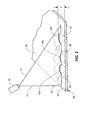
- Fig.2 is an example of an instantaneous single laser profile image of three pears 31-33.
- the image shown in Fig.2 includes a laser profiling line 15 that represents the intersection of a laser "sheet-of-light" (see Fig.1 , item 11) with the surfaces of three pears 31-33, the outlines of which are shown in phantom (or dotted lines) in Fig.2 .
- the laser "sheet-of-light" 11 momentarily intersects the shoulders or sides of pears 31-33 and forms bright lines 15a, 15b and 15c on pears 31-33 respectively.
- the vertical position h, of profiling line 15 represents the height of the pear surface above the conveyor surface at that particular point where the "sheet-of-light” intersects the pear surface.
- the "sheet-of-light” output 11 is caused to periodically and at frequent intervals impact the surfaces of the produce items to create instantaneous laser profiles of those surfaces.
- the most desirable portion of the surface of each produce item on which to place a label is the highest region, or "dome", of each produce item.
- the "dome” is the flattest surface which most easily accepts an adhesive label, and which reflects more of the sheet-of-light 11 than any other portion of the surface of the pear.
- the "dome” is also the highest surface, which requires the minimum travel (and minimum time) for the labeling machine head to apply any given label.
- conveyor 90 has a flat upper surface 91 on which produce trays (not shown in Fig.2 ) carry an array of produce items toward a high speed labeler. No produce tray is shown in Fig.2 for clarity.
- Each of pears 31-33 has a dome portion of its surface 31a-33a respectively which occurs at the greatest height of said pear above the upper surface 91 of conveyor 90.
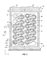
- Fig.3 is a two dimensional image showing the "real world" horizontal or (x,y) coordinates for an array of 21 pears shown generally as 130 carried in a tray 98 having 24 receptacles shown generally as 97.
- the pears 130 are moving toward labeling machine 99 along the longitudinal axis A-A of conveyor 90.
- Conveyor 90 has a flat surface 91.
- the receptacles 97 cradle each of the pears 130.
- Cradles 97a, 97b and 97c are empty and carry no pears.
- the laser and camera are not shown for clarity.
- a single pear 131 will be described.
- the dome 131 a of pear 131 is a generally flat and smooth surface bounded by a generally oval ring 131b.
- Rings 131b, 131c and 131d are essentially contour or topographic rings showing the shape of the upper half of pear 131. It is significant to note that the region between rings 131b and 131c reflects less light and appears darker than the dome 131 a. Similarly, the region between ring 131c and 131 d reflects even less light and appears even darker.
- the relative brightnesses of light reflected from the different portions of the surface of each pear are used to locate the dome of each pear and create (x,y) coordinates for each dome.
- An important aspect of the invention is to utilize the laser profiling technique to locate the positions of the "domes" of incoming produce items and to give the labeling machine "advance notice" of the real world coordinates of those "domes".
- the laser 110 and camera 120 are shown schematically in Fig.3 .
- the sheet-of-light (not shown for clarity) generated by laser 110 is preferably oriented perpendicularly to axis A-A, but other orientations transverse to axis A-A can be utilized.
- the laser 110 and camera 120 may be mounted directly over conveyor 90 or off to the side of conveyor 90 as shown in Fig.3 .
- the camera lens, sensor resolution and view point are optimized to image produce trays stacked up to three high with sufficient height resolution to recover coordinates to within an accuracy typically ⁇ 3mm.
- the sensitivity of the sensor and brightness of the laser are optimized to ensure operation with fruit that is very dark and non-reflective to red laser light.
- Every laser profile image ( Figure 2 ) provides positional information for a single line across the tray. As the tray progresses along the conveyor, images are continuously taken at a very high frame rate in order to build up a complete depth map of the tray.
- Fig.3 is a resulting depth map, and is a 2-D image, with height encoded as relative grayscale brightness with each dome having the greatest brightness, and the surface areas of each pear have a lower relative brightness the further they are below the dome. Positions of fruit and empty tray locations can be measured from the depth image, since fruit has a characteristic "domed" height profile as shown in Fig.3 .
- the depth image produces a result that is relatively unaffected by typical problems associated with conventional imaging. Depth images in the present system are relatively unaffected by:
- the system In order to produce useful height or z coordinates, the system must be calibrated to convert positions in the depth image into real-world (x,y,z) coordinates that the labeling system can use. Primarily, the positions of detected fruit in the image must be converted into world coordinates. This involves the transform of pixel positions (x,y) and grayscale brightness (g) into world (x,y,z) millimeters relative to the position of a detected tray.
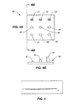
- Figs.4A and 4B illustrates a calibration target 60 comprised of nine cylindrical spikes 61-69 arranged in a 3x3 pattern, with three rows of increasing height spikes 61-63 having the smallest height and spikes 67-69 having the greatest height.
- the relative brightness of reflections from spikes 67-69 is greater than that of reflections from spikes 64-66 and corresponds to a given height of a surface area of a pear or other produce item and the relative brightness of reflections from spikes 64-66 is greater than that from spikes 61-63.
- Calibration target 60 provides known reference brightness measurements and is utilized to assure that the relative brightnesses of reflections from produce surfaces corresponds to real world height measurements and coordinates.
- a projective calibration is used to calibrate the transform between the image position and grayscale (x,g) into world (x,z) coordinates.
- the down-conveyor scale is a fixed factor and is held constant by an encoder on the belt that ensures that a consistent number of profiles per millimeter are exposed by the sensor.
- Fig.5 illustrates how lens calibration is achieved for the system.
- a small amount of radial lens distortion is present for the "C" mount lens used in the system. This effect introduces a visible curvature ( Fig.5 ) to the perfectly straight laser sheet of light line when imaged, which must be measured during calibration and compensated during calibration and use.
- the Hough Transform (modified) is used to detect the pears (or other produce item) in the depth map images of Fig.3 .
- the Hough Transform is described at E. R. Davies 'Machine Vision: Theory, Algorithms, Practice', Academic Press 1997, ISBN:0-12-206092-x .
- the Hough Transform is modified by bypassing the usual edge detection stage and instead integrating all positive gradient information across the image. This turns the transform from a circle detector to a 'dome' detector when used with the depth image.
- Figs.6A and 6B illustrate schematically the difference in image quality of a tray of pears before ( Fig.6A ) and after ( Fig.6B ) application of the modified Hough Transform.
- the pear images are relatively diffuse and without a clear indication of where the dome of each pear is located.
- Fig.6B illustrates the domes as 231 generally.
- Accent marks 232 have been added to indicate the enhanced brightness of each dome 231 after the application of the modified Hough Transform.
- the coordinates of the enhanced dome images shown in Fig.6B are passed to the labeling machines.
- the horizontal or (x,y) coordinates are passed to the labeling machines along with the largest height or z coordinate in any given tray or array of produce items.
- a less preferred embodiment simply passes the horizontal or (x,y) coordinates to the labeling machines.
- a further embodiment passes all height or z coordinates to the labeling machines.
- the present invention may be used together with known labeling machines shown and described or referred to in U.S. Patent Nos. 7,168,472 and 7,837,823 .
- the present invention may also be used together with other known labeling machines available from Sinclair Systems International, LLC located at 3115 S. Willow Avenue, Fresno, CA 93725.
Landscapes
- Physics & Mathematics (AREA)
- General Physics & Mathematics (AREA)
- Engineering & Computer Science (AREA)
- Computer Vision & Pattern Recognition (AREA)
- Length Measuring Devices By Optical Means (AREA)
Description
- The present invention pertains to automatic, high speed produce labeling machines. More particularly, the present invention provides a technique for increasing the labeling speed while maintaining a high efficiency of operation. The efficiency of operation includes the proper placement of labels on produce items as well as placing labels on all produce items presented to the automatic labeling machine. There is a constant demand for higher speed labeling systems, provided that the efficiency of label application is not reduced at higher speed. By way of background, such automatic labeling machines typically apply 720 labels per minute per labeling head to produce items approaching the labeler at speeds of about 75 meters per minute.
- Previous attempts to scan incoming produce items to provide "advance data" to the automatic labeler regarding location of those items on the conveyor have been attempted. All such prior systems known to the applicant(s) have been sensitive to, and scanning results affected by color variables such as changes in produce variety, produce color, tray liner color and tray liner material color. Color variations affected the system performance significantly, and limit the speed and efficiency of those systems.
- The present invention provides a system in which the color variables of the produce item, carrying tray and various items such as straw that occasionally appear in the trays, do not affect the performance of the system.
- Known systems to identify produce items on a conveyor belt by imaging a projected line of light are described in patent documents
US 6 133 948 ,US 6 349 755 andUS 4 929 843 . - The present invention, for the first time known to the applicant(s), utilizes a laser profiling system to repeatedly scan the produce items moving on a conveyor at high speed toward the labeling machine. The laser profiling system provides "advance data" to the labeling machine regarding the location and preferably also the size (or height) of the fast moving produce items. This "advance data" is used instantaneously by the labeling machine to anticipate when and where to place labels on those produce items.
- The present invention uses laser (or other high intensity light source) profiling to identify the horizontal or (x, y) location of produce items in a tray or on a conveyor belt as the items approach the labeler. The present invention, in a preferred embodiment, also uses laser profiling to identify the size, or height, of produce items (on a z axis). The height of produce items is related to the brightness of the image, as described below. The laser profiling produces "real world" (x, y, z) coordinates that are passed to the labeler at high frequency and instantaneously. We have found that, as a practical matter, for a given tray carrying multiple produce items, such as pears for example, the only z or height coordinate passed to the labeler is the coordinate for the maximum height for that given tray. Alternatively, all z or height coordinates may be passed to the labeler; the labeler can then be programmed to respond only to the maximum height in the given tray or to respond to two or more different heights in any given tray. Once the labeler knows the coordinates of the approaching produce items, labeling speeds can be increased without a loss of labeling efficiency.
- As noted above, the present system differs from the prior art known to applicant(s) in that it is not sensitive to, or adversely affected by, color changes or color variables in any of the objects being scanned; i.e. produce items, carrying trays and detritus in those trays.
- One object of the invention is to provide a laser(or other high intensity light source) profiling system to provide real world horizontal (x,y) coordinates locating the instantaneous position of the domes of produce items as they approach an automatic high speed labeling machine.
- A further object of the invention is to utilize a laser profiling system to provide real world (x, y, z) coordinates locating the instantaneous position and height of the domes of produce items as they approach an automatic, high speed labeling machine, which system is unaffected by color variables occurring in the produce items, carrying trays, and detritus in the carrying trays.
- A further object of the invention is to increase the speed of automatic produce labeling machines while maintaining the efficiency of those machines in accurately applying the labels.
- The objects are met and the scope of the invention is defined by the claims.
-
-
Fig. 1 is a schematic illustration showing how the laser profiling technique may be used to obtain height (or z axis) information of various objects; -
Fig. 2 is a schematic illustration showing how laser profiling is used in the invention to obtain instantaneous height (or depth) information for a row of produce items such as pears; -
Fig. 3 is an instantaneous image looking downwardly at a tray of pears, wherein the brightness of reflected light corresponds to height; -
Fig. 4 illustrates a calibration target used to transform an image position into real world (x, y, z) coordinates; -
Fig. 5 illustrates radial lens distortion which is measured during calibration of the invention and compensated for during processing; and -
Figs. 6A and 6B are "depth map" images before and after application of the "domes" algorithm, whereinFig. 6B clearly locates the "dome" or highest point of the produce item. - As shown in
Fig.1 , laser profiling involves the projection of a light pattern from alaser 10, usually a plane, at a known angle onto an object orobjects - The light pattern is generated by fanning out a light beam into a planar sheet-of-
light 11. When sheet-of-light 11 intersects with an object, a bright line of light can be seen on the surface of the object. By viewing this line of light from an angle with acamera 20 the observed distortions in the line can be translated intoheight variations 19 shown onmonitor 25. -
Fig.2 is an example of an instantaneous single laser profile image of three pears 31-33. The image shown inFig.2 includes alaser profiling line 15 that represents the intersection of a laser "sheet-of-light" (seeFig.1 , item 11) with the surfaces of three pears 31-33, the outlines of which are shown in phantom (or dotted lines) inFig.2 . InFig.2 , the laser "sheet-of-light" 11 momentarily intersects the shoulders or sides of pears 31-33 and formsbright lines profiling line 15 represents the height of the pear surface above the conveyor surface at that particular point where the "sheet-of-light" intersects the pear surface. The "sheet-of-light"output 11 is caused to periodically and at frequent intervals impact the surfaces of the produce items to create instantaneous laser profiles of those surfaces. - The most desirable portion of the surface of each produce item on which to place a label is the highest region, or "dome", of each produce item. The "dome" is the flattest surface which most easily accepts an adhesive label, and which reflects more of the sheet-of-
light 11 than any other portion of the surface of the pear. The "dome" is also the highest surface, which requires the minimum travel (and minimum time) for the labeling machine head to apply any given label. - As shown in
Fig.2 ,conveyor 90 has a flatupper surface 91 on which produce trays (not shown inFig.2 ) carry an array of produce items toward a high speed labeler. No produce tray is shown inFig.2 for clarity. - Each of pears 31-33 has a dome portion of its surface 31a-33a respectively which occurs at the greatest height of said pear above the
upper surface 91 ofconveyor 90. -
Fig.3 is a two dimensional image showing the "real world" horizontal or (x,y) coordinates for an array of 21 pears shown generally as 130 carried in atray 98 having 24 receptacles shown generally as 97. The pears 130 are moving towardlabeling machine 99 along the longitudinal axis A-A ofconveyor 90.Conveyor 90 has aflat surface 91. Thereceptacles 97 cradle each of the pears 130. Cradles 97a, 97b and 97c are empty and carry no pears. The laser and camera are not shown for clarity. - A
single pear 131 will be described. Thedome 131 a ofpear 131 is a generally flat and smooth surface bounded by a generallyoval ring 131b.Rings pear 131. It is significant to note that the region betweenrings dome 131 a. Similarly, the region betweenring - An important aspect of the invention is to utilize the laser profiling technique to locate the positions of the "domes" of incoming produce items and to give the labeling machine "advance notice" of the real world coordinates of those "domes".
- The
laser 110 andcamera 120 are shown schematically inFig.3 . The sheet-of-light (not shown for clarity) generated bylaser 110 is preferably oriented perpendicularly to axis A-A, but other orientations transverse to axis A-A can be utilized. Thelaser 110 andcamera 120 may be mounted directly overconveyor 90 or off to the side ofconveyor 90 as shown inFig.3 . - The camera lens, sensor resolution and view point are optimized to image produce trays stacked up to three high with sufficient height resolution to recover coordinates to within an accuracy typically < 3mm. The sensitivity of the sensor and brightness of the laser are optimized to ensure operation with fruit that is very dark and non-reflective to red laser light. Every laser profile image (
Figure 2 ) provides positional information for a single line across the tray. As the tray progresses along the conveyor, images are continuously taken at a very high frame rate in order to build up a complete depth map of the tray. -
Fig.3 is a resulting depth map, and is a 2-D image, with height encoded as relative grayscale brightness with each dome having the greatest brightness, and the surface areas of each pear have a lower relative brightness the further they are below the dome. Positions of fruit and empty tray locations can be measured from the depth image, since fruit has a characteristic "domed" height profile as shown inFig.3 . The depth image produces a result that is relatively unaffected by typical problems associated with conventional imaging. Depth images in the present system are relatively unaffected by: - Lack of color contrast between the fruit and tray (e.g. green apples on a green tray)
- Lack of brightness/luminance contrast between the fruit and tray (e.g. dark plums on a dark tray)
- Problematic tray materials (reflective and semi-transparent trays etc)
- Trays packed with material such as straw or other detritus.
- In order to produce useful height or z coordinates, the system must be calibrated to convert positions in the depth image into real-world (x,y,z) coordinates that the labeling system can use. Primarily, the positions of detected fruit in the image must be converted into world coordinates. This involves the transform of pixel positions (x,y) and grayscale brightness (g) into world (x,y,z) millimeters relative to the position of a detected tray.
-
Figs.4A and 4B illustrates acalibration target 60 comprised of nine cylindrical spikes 61-69 arranged in a 3x3 pattern, with three rows of increasing height spikes 61-63 having the smallest height and spikes 67-69 having the greatest height. The relative brightness of reflections from spikes 67-69 is greater than that of reflections from spikes 64-66 and corresponds to a given height of a surface area of a pear or other produce item and the relative brightness of reflections from spikes 64-66 is greater than that from spikes 61-63.Calibration target 60 provides known reference brightness measurements and is utilized to assure that the relative brightnesses of reflections from produce surfaces corresponds to real world height measurements and coordinates. A projective calibration is used to calibrate the transform between the image position and grayscale (x,g) into world (x,z) coordinates. The down-conveyor scale is a fixed factor and is held constant by an encoder on the belt that ensures that a consistent number of profiles per millimeter are exposed by the sensor. -
Fig.5 illustrates how lens calibration is achieved for the system. A small amount of radial lens distortion is present for the "C" mount lens used in the system. This effect introduces a visible curvature (Fig.5 ) to the perfectly straight laser sheet of light line when imaged, which must be measured during calibration and compensated during calibration and use. - The Hough Transform (modified) is used to detect the pears (or other produce item) in the depth map images of
Fig.3 . The Hough Transform is described at E. R. Davies 'Machine Vision: Theory, Algorithms, Practice', Academic Press 1997, ISBN:0-12-206092-x. The Hough Transform is modified by bypassing the usual edge detection stage and instead integrating all positive gradient information across the image. This turns the transform from a circle detector to a 'dome' detector when used with the depth image. - Application of the algorithm enhances any positive, approximately round domes in the image. The technique works well on all fruit tried. Peaks in the transformed image are detected via a threshold and blob analysis stage, their centroids are computed and then converted to world (x,y,z) coordinates using the calibration information. The application framework then passes this coordinate information to the labeling subsystem (or labeling machines).
-
Figs.6A and 6B illustrate schematically the difference in image quality of a tray of pears before (Fig.6A ) and after (Fig.6B ) application of the modified Hough Transform. As shown inFig.6A , the pear images are relatively diffuse and without a clear indication of where the dome of each pear is located.Fig.6B illustrates the domes as 231 generally. Accent marks 232 have been added to indicate the enhanced brightness of eachdome 231 after the application of the modified Hough Transform. The coordinates of the enhanced dome images shown inFig.6B are passed to the labeling machines. In the preferred embodiment of the system, the horizontal or (x,y) coordinates are passed to the labeling machines along with the largest height or z coordinate in any given tray or array of produce items. A less preferred embodiment simply passes the horizontal or (x,y) coordinates to the labeling machines. A further embodiment passes all height or z coordinates to the labeling machines. - The present invention may be used together with known labeling machines shown and described or referred to in
U.S. Patent Nos. 7,168,472 and7,837,823 . The present invention may also be used together with other known labeling machines available from Sinclair Systems International, LLC located at 3115 S. Willow Avenue, Fresno, CA 93725. - The foregoing description of the invention has been presented for purposes of illustration and description and is not intended to be exhaustive or to limit the invention to the precise forms disclosed. The scope of the invention is defined by the claims. Modifications and variations are possible in light of the above teaching. For example, high intensity light sources capable of generating a sheet of light may be utilized instead of lasers. Such light sources include any light source capable of creating a sheet of light instantaneously and momentarily that generates a reflection similar to the sheet of light generated by laser profiling. The embodiments were chosen and described to best explain the principles of the invention and its practical application to thereby enable others skilled in the art to best use the invention in various embodiments and with various modifications suited to the particular use contemplated.
Claims (6)
- A vision recognition method for use with a high speed, automatic produce labeling machine (99), wherein a conveyor (90) feeds incoming produce items (31 - 33, 131) along an axis A-A toward said labeling machine, wherein each produce item has a dome portion (131a) of its surface which occurs at the greatest height of said produce item's surface above said conveyor, comprising the steps:generating a sheet of light (11) from a laser source (10, 110) or other high intensity light source,directing said sheet of light transversely to said axis A-A of said conveyor,causing said sheet of light to periodically impact and reflect from the surfaces of said produce items to create instantaneous laser profiles of said surfaces,continuously imaging said laser profiles with a high speed camera (20, 120),locating the dome of each produce item by comparing the relative brightness of the reflections of said sheet of light from different portions of the surface of each produce item, and by identifying the portion of said surface that reflects the most light and shows the greatest relative brightness,creating real world coordinates (x,y) for the instantaneous location of said domes of said produce items horizontally on said conveyor, andtransmitting said instantaneous real world horizontal (x,y) coordinates periodically to said labeling machine to provide advance data to said labeling machine regarding the real world horizontal location (x,y coordinates) of the dome of each incoming produce item to be labeled.
- The method of claim 1 comprising the further step:creating a height or z coordinate for at least some of said domes by comparing the brightness of said reflection of light from said dome with known reference brightness measurements, andtransmitting said height or z coordinates to said labeling machine.
- The method of claim 2 comprising the further step:selecting the largest height or z coordinate from a selected number of said height or z coordinates, andtransmitting said largest height or z coordinate to said labeling machine.
- The method of claim 2 wherein said height or z coordinates are created for all of said domes and transmitted to said labeling machine.
- The method of claim 1 wherein said different portions of said surface each form topographic rings showing the shape of the upper half of each said produce item.
- The method of claim 1 comprising the further step:generating a 2-D map of said produce items from said laser profiles.
Applications Claiming Priority (2)
| Application Number | Priority Date | Filing Date | Title |
|---|---|---|---|
| US40327210P | 2010-09-13 | 2010-09-13 | |
| PCT/US2011/001566 WO2012036725A1 (en) | 2010-09-13 | 2011-09-12 | Vision recognition system for produce labeling |
Publications (3)
| Publication Number | Publication Date |
|---|---|
| EP2616762A1 EP2616762A1 (en) | 2013-07-24 |
| EP2616762A4 EP2616762A4 (en) | 2014-06-25 |
| EP2616762B1 true EP2616762B1 (en) | 2015-08-19 |
Family
ID=45817492
Family Applications (1)
| Application Number | Title | Priority Date | Filing Date |
|---|---|---|---|
| EP11825554.6A Not-in-force EP2616762B1 (en) | 2010-09-13 | 2011-09-12 | Vision recognition system for produce labeling |
Country Status (11)
| Country | Link |
|---|---|
| US (1) | US8456646B2 (en) |
| EP (1) | EP2616762B1 (en) |
| CN (1) | CN103097856B (en) |
| AU (1) | AU2011302624B9 (en) |
| CA (1) | CA2809414C (en) |
| CL (1) | CL2013000633A1 (en) |
| ES (1) | ES2548874T3 (en) |
| IL (1) | IL224581A (en) |
| MX (1) | MX2013002795A (en) |
| NZ (1) | NZ606235A (en) |
| WO (1) | WO2012036725A1 (en) |
Families Citing this family (13)
| Publication number | Priority date | Publication date | Assignee | Title |
|---|---|---|---|---|
| US9304089B2 (en) * | 2013-04-05 | 2016-04-05 | Mitutoyo Corporation | System and method for obtaining images with offset utilized for enhanced edge resolution |
| US9605950B2 (en) | 2013-05-22 | 2017-03-28 | Cognex Corporation | System and method for efficient surface measurement using a laser displacement sensor |
| DE102014107143B4 (en) * | 2013-05-22 | 2021-03-04 | Cognex Corp. | System and method for measuring the displacement of an object surface |
| ITBO20130359A1 (en) * | 2013-07-10 | 2015-01-11 | Mac & Label Trade S R L | AN APPARATUS FOR THE TREATMENT OF THEIR RESPECTIVE PRODUCTS, IN PARTICULAR TO LABEL THESE PRODUCTS. |
| CN104713882B (en) * | 2015-04-07 | 2017-07-18 | 何益明 | Bamboo silk or bamboo chip positive and negative discrimination method and its device |
| AU2017238652B2 (en) | 2016-03-24 | 2022-04-21 | Sumier SLEIMAN | Labeller and method of using the same |
| US20180042176A1 (en) * | 2016-08-15 | 2018-02-15 | Raptor Maps, Inc. | Systems, devices, and methods for monitoring and assessing characteristics of harvested specialty crops |
| CN106546185B (en) * | 2016-10-18 | 2019-09-20 | 福州觉感视觉软件科技有限公司 | A kind of profile quality determining method based on Machine Vision Detection |
| JP6813394B2 (en) * | 2017-03-03 | 2021-01-13 | リコーエレメックス株式会社 | Image inspection equipment |
| CN110451045B (en) * | 2018-05-08 | 2021-11-02 | 拓卡奔马机电科技有限公司 | Labeling position control method, control system, storage medium, and labeling machine |
| CN111572926A (en) * | 2020-06-03 | 2020-08-25 | 江苏久茂精密电子科技有限公司 | Notebook is with pasting auxiliary material device |
| IT202100029777A1 (en) * | 2021-11-25 | 2023-05-25 | Itasystem S R L | Improved apparatus for labeling food products |
| CN118376185B (en) * | 2024-04-03 | 2024-12-17 | 青岛泰威达电子有限公司 | Laser measuring device of LCD display screen and display screen manufacturing equipment |
Family Cites Families (11)
| Publication number | Priority date | Publication date | Assignee | Title |
|---|---|---|---|---|
| KR900006577B1 (en) * | 1986-10-03 | 1990-09-13 | 엔티티 기쥬쯔이덴 가부시끼가이샤 | Shape measuring instrument |
| JP2555058B2 (en) * | 1987-03-24 | 1996-11-20 | 株式会社吉野工業所 | Label inspection method |
| FR2624601B1 (en) * | 1987-12-11 | 1990-05-25 | Tech Bois Ameublement Centre | VIDEO-LASER DETECTION DEVICE FOR DETERMINING GEOMETRIC CHARACTERISTICS OF AN OBJECT |
| US4929843A (en) * | 1989-06-28 | 1990-05-29 | General Electric Company | Apparatus and method for determining a dimension of an object |
| US6133948A (en) * | 1995-12-04 | 2000-10-17 | Virginia Tech Intellectual Properties, Inc. | Automatic identification of articles having contoured surfaces |
| US5791497A (en) * | 1996-05-08 | 1998-08-11 | Src Vision, Inc. | Method of separating fruit or vegetable products |
| US6219438B1 (en) | 1997-09-02 | 2001-04-17 | Lucent Technologies Inc. | Produce indentifier using barcode scanner and wavelet image processing and having compensation for dirt accumulated on viewing window |
| FR2796143B1 (en) * | 1999-07-07 | 2001-09-21 | Xeda International | DEVICE FOR EVALUATING THE GEOMETRY OF ARTICLES TRANSPORTED BY A CONVEYOR |
| US7161688B1 (en) | 1999-08-31 | 2007-01-09 | Brett Bonner | Mass scanning and dimensioning system |
| US7153378B2 (en) | 2003-11-21 | 2006-12-26 | Joe & Samia Management Inc. | Product labelling |
| US7168472B2 (en) * | 2004-03-03 | 2007-01-30 | Sinclair Systems International, Llc | Method and apparatus for applying variable coded labels to items of produce |
-
2011
- 2011-09-12 MX MX2013002795A patent/MX2013002795A/en active IP Right Grant
- 2011-09-12 CA CA2809414A patent/CA2809414C/en not_active Expired - Fee Related
- 2011-09-12 WO PCT/US2011/001566 patent/WO2012036725A1/en not_active Ceased
- 2011-09-12 US US13/199,876 patent/US8456646B2/en not_active Expired - Fee Related
- 2011-09-12 AU AU2011302624A patent/AU2011302624B9/en not_active Ceased
- 2011-09-12 NZ NZ606235A patent/NZ606235A/en not_active IP Right Cessation
- 2011-09-12 EP EP11825554.6A patent/EP2616762B1/en not_active Not-in-force
- 2011-09-12 CN CN201180043789.3A patent/CN103097856B/en not_active Expired - Fee Related
- 2011-09-12 ES ES11825554.6T patent/ES2548874T3/en active Active
-
2013
- 2013-02-05 IL IL224581A patent/IL224581A/en active IP Right Grant
- 2013-03-06 CL CL2013000633A patent/CL2013000633A1/en unknown
Also Published As
| Publication number | Publication date |
|---|---|
| IL224581A (en) | 2016-07-31 |
| WO2012036725A8 (en) | 2012-11-08 |
| AU2011302624A1 (en) | 2013-02-14 |
| US20120069354A1 (en) | 2012-03-22 |
| US8456646B2 (en) | 2013-06-04 |
| ES2548874T3 (en) | 2015-10-21 |
| CN103097856A (en) | 2013-05-08 |
| EP2616762A4 (en) | 2014-06-25 |
| CA2809414C (en) | 2014-07-15 |
| CL2013000633A1 (en) | 2013-11-15 |
| EP2616762A1 (en) | 2013-07-24 |
| NZ606235A (en) | 2014-08-29 |
| CN103097856B (en) | 2016-03-16 |
| AU2011302624B9 (en) | 2014-04-17 |
| AU2011302624B2 (en) | 2014-03-20 |
| WO2012036725A1 (en) | 2012-03-22 |
| MX2013002795A (en) | 2013-05-09 |
| CA2809414A1 (en) | 2012-03-22 |
Similar Documents
| Publication | Publication Date | Title |
|---|---|---|
| CA2809414C (en) | Vision recognition system for produce labeling | |
| CN111919105B (en) | Method and system for online monitoring and control of beverage can color decoration specifications | |
| US20140098223A1 (en) | Size measurement apparatus and size measurement method | |
| EP1738136B1 (en) | Measuring apparatus and method in a distribution system | |
| EP2321963B1 (en) | Scanned beam overlay projection | |
| JPH10332320A (en) | Product scanning device and method | |
| CZ299731B6 (en) | Method of inspecting container and identifying variations that affect commercial acceptability of the container and apparatus for making the same | |
| US11195042B2 (en) | Drug inspection assistance device, drug identification device, image processing device, image processing method, and program | |
| US20180172602A1 (en) | System and method for inspecting containers using multiple radiation sources | |
| WO2017011901A1 (en) | Methods and systems for laser marking an identifier on an industrial product | |
| US20090084855A1 (en) | Methods and Apparatus for Directing Bar Code Positioning for Imaging Scanning | |
| US20060067572A1 (en) | Object imaging system | |
| EP3353488B1 (en) | Method for measuring the 3d profile of an objet | |
| CN104662412A (en) | Method of operating a radiographic inspection system with a modular conveyor chain | |
| TWI497059B (en) | Multi - surface detection system and method | |
| US11448501B2 (en) | Image capturing system and a method for determining the position of an embossed structure on a sheet element | |
| DK2297674T3 (en) | Optical registration and classification of returned packaging items in a return system | |
| WO2011087454A1 (en) | Apparatus and methods for manipulating and acquiring images of a pallet load | |
| CN207643734U (en) | Detecting system and the 3D printing equipment being applicable in | |
| JPH10222608A (en) | Character inspection method and apparatus | |
| US20240386736A1 (en) | Dot code detection | |
| WO2011123057A1 (en) | Apparatus and methods for acquiring and analysing images of a pallet load | |
| CN121347529A (en) | An automatic detection device and method for die-cut roll materials | |
| CN120822971A (en) | One-item-one-code full life cycle tracking system | |
| WO2014191819A2 (en) | Method and device for estimating an edge position of an object, such as cans, bottles and packaging, using image data in frames of said object, computer program and computer program product |
Legal Events
| Date | Code | Title | Description |
|---|---|---|---|
| PUAI | Public reference made under article 153(3) epc to a published international application that has entered the european phase |
Free format text: ORIGINAL CODE: 0009012 |
|
| 17P | Request for examination filed |
Effective date: 20130128 |
|
| AK | Designated contracting states |
Kind code of ref document: A1 Designated state(s): AL AT BE BG CH CY CZ DE DK EE ES FI FR GB GR HR HU IE IS IT LI LT LU LV MC MK MT NL NO PL PT RO RS SE SI SK SM TR |
|
| DAX | Request for extension of the european patent (deleted) | ||
| A4 | Supplementary search report drawn up and despatched |
Effective date: 20140522 |
|
| RIC1 | Information provided on ipc code assigned before grant |
Ipc: G01B 11/24 20060101AFI20140516BHEP Ipc: G01B 11/25 20060101ALI20140516BHEP Ipc: G01B 11/06 20060101ALI20140516BHEP Ipc: B65C 9/40 20060101ALI20140516BHEP |
|
| GRAP | Despatch of communication of intention to grant a patent |
Free format text: ORIGINAL CODE: EPIDOSNIGR1 |
|
| INTG | Intention to grant announced |
Effective date: 20150421 |
|
| GRAS | Grant fee paid |
Free format text: ORIGINAL CODE: EPIDOSNIGR3 |
|
| GRAA | (expected) grant |
Free format text: ORIGINAL CODE: 0009210 |
|
| AK | Designated contracting states |
Kind code of ref document: B1 Designated state(s): AL AT BE BG CH CY CZ DE DK EE ES FI FR GB GR HR HU IE IS IT LI LT LU LV MC MK MT NL NO PL PT RO RS SE SI SK SM TR |
|
| REG | Reference to a national code |
Ref country code: GB Ref legal event code: FG4D |
|
| REG | Reference to a national code |
Ref country code: CH Ref legal event code: EP |
|
| REG | Reference to a national code |
Ref country code: IE Ref legal event code: FG4D |
|
| REG | Reference to a national code |
Ref country code: AT Ref legal event code: REF Ref document number: 744120 Country of ref document: AT Kind code of ref document: T Effective date: 20150915 |
|
| REG | Reference to a national code |
Ref country code: DE Ref legal event code: R096 Ref document number: 602011019022 Country of ref document: DE |
|
| REG | Reference to a national code |
Ref country code: FR Ref legal event code: PLFP Year of fee payment: 5 |
|
| REG | Reference to a national code |
Ref country code: ES Ref legal event code: FG2A Ref document number: 2548874 Country of ref document: ES Kind code of ref document: T3 Effective date: 20151021 |
|
| REG | Reference to a national code |
Ref country code: NL Ref legal event code: FP |
|
| REG | Reference to a national code |
Ref country code: LT Ref legal event code: MG4D |
|
| PG25 | Lapsed in a contracting state [announced via postgrant information from national office to epo] |
Ref country code: NO Free format text: LAPSE BECAUSE OF FAILURE TO SUBMIT A TRANSLATION OF THE DESCRIPTION OR TO PAY THE FEE WITHIN THE PRESCRIBED TIME-LIMIT Effective date: 20151119 Ref country code: GR Free format text: LAPSE BECAUSE OF FAILURE TO SUBMIT A TRANSLATION OF THE DESCRIPTION OR TO PAY THE FEE WITHIN THE PRESCRIBED TIME-LIMIT Effective date: 20151120 Ref country code: LV Free format text: LAPSE BECAUSE OF FAILURE TO SUBMIT A TRANSLATION OF THE DESCRIPTION OR TO PAY THE FEE WITHIN THE PRESCRIBED TIME-LIMIT Effective date: 20150819 Ref country code: FI Free format text: LAPSE BECAUSE OF FAILURE TO SUBMIT A TRANSLATION OF THE DESCRIPTION OR TO PAY THE FEE WITHIN THE PRESCRIBED TIME-LIMIT Effective date: 20150819 Ref country code: LT Free format text: LAPSE BECAUSE OF FAILURE TO SUBMIT A TRANSLATION OF THE DESCRIPTION OR TO PAY THE FEE WITHIN THE PRESCRIBED TIME-LIMIT Effective date: 20150819 |
|
| PG25 | Lapsed in a contracting state [announced via postgrant information from national office to epo] |
Ref country code: PL Free format text: LAPSE BECAUSE OF FAILURE TO SUBMIT A TRANSLATION OF THE DESCRIPTION OR TO PAY THE FEE WITHIN THE PRESCRIBED TIME-LIMIT Effective date: 20150819 Ref country code: IS Free format text: LAPSE BECAUSE OF FAILURE TO SUBMIT A TRANSLATION OF THE DESCRIPTION OR TO PAY THE FEE WITHIN THE PRESCRIBED TIME-LIMIT Effective date: 20151219 Ref country code: PT Free format text: LAPSE BECAUSE OF FAILURE TO SUBMIT A TRANSLATION OF THE DESCRIPTION OR TO PAY THE FEE WITHIN THE PRESCRIBED TIME-LIMIT Effective date: 20151221 Ref country code: RS Free format text: LAPSE BECAUSE OF FAILURE TO SUBMIT A TRANSLATION OF THE DESCRIPTION OR TO PAY THE FEE WITHIN THE PRESCRIBED TIME-LIMIT Effective date: 20150819 Ref country code: SE Free format text: LAPSE BECAUSE OF FAILURE TO SUBMIT A TRANSLATION OF THE DESCRIPTION OR TO PAY THE FEE WITHIN THE PRESCRIBED TIME-LIMIT Effective date: 20150819 |
|
| PG25 | Lapsed in a contracting state [announced via postgrant information from national office to epo] |
Ref country code: SK Free format text: LAPSE BECAUSE OF FAILURE TO SUBMIT A TRANSLATION OF THE DESCRIPTION OR TO PAY THE FEE WITHIN THE PRESCRIBED TIME-LIMIT Effective date: 20150819 Ref country code: EE Free format text: LAPSE BECAUSE OF FAILURE TO SUBMIT A TRANSLATION OF THE DESCRIPTION OR TO PAY THE FEE WITHIN THE PRESCRIBED TIME-LIMIT Effective date: 20150819 Ref country code: CZ Free format text: LAPSE BECAUSE OF FAILURE TO SUBMIT A TRANSLATION OF THE DESCRIPTION OR TO PAY THE FEE WITHIN THE PRESCRIBED TIME-LIMIT Effective date: 20150819 Ref country code: DK Free format text: LAPSE BECAUSE OF FAILURE TO SUBMIT A TRANSLATION OF THE DESCRIPTION OR TO PAY THE FEE WITHIN THE PRESCRIBED TIME-LIMIT Effective date: 20150819 |
|
| REG | Reference to a national code |
Ref country code: CH Ref legal event code: PL |
|
| REG | Reference to a national code |
Ref country code: DE Ref legal event code: R097 Ref document number: 602011019022 Country of ref document: DE |
|
| PG25 | Lapsed in a contracting state [announced via postgrant information from national office to epo] |
Ref country code: RO Free format text: LAPSE BECAUSE OF FAILURE TO SUBMIT A TRANSLATION OF THE DESCRIPTION OR TO PAY THE FEE WITHIN THE PRESCRIBED TIME-LIMIT Effective date: 20150819 Ref country code: MC Free format text: LAPSE BECAUSE OF FAILURE TO SUBMIT A TRANSLATION OF THE DESCRIPTION OR TO PAY THE FEE WITHIN THE PRESCRIBED TIME-LIMIT Effective date: 20150819 |
|
| PLBE | No opposition filed within time limit |
Free format text: ORIGINAL CODE: 0009261 |
|
| STAA | Information on the status of an ep patent application or granted ep patent |
Free format text: STATUS: NO OPPOSITION FILED WITHIN TIME LIMIT |
|
| REG | Reference to a national code |
Ref country code: IE Ref legal event code: MM4A |
|
| 26N | No opposition filed |
Effective date: 20160520 |
|
| PG25 | Lapsed in a contracting state [announced via postgrant information from national office to epo] |
Ref country code: IE Free format text: LAPSE BECAUSE OF NON-PAYMENT OF DUE FEES Effective date: 20150912 Ref country code: LI Free format text: LAPSE BECAUSE OF NON-PAYMENT OF DUE FEES Effective date: 20150930 Ref country code: CH Free format text: LAPSE BECAUSE OF NON-PAYMENT OF DUE FEES Effective date: 20150930 |
|
| PG25 | Lapsed in a contracting state [announced via postgrant information from national office to epo] |
Ref country code: SI Free format text: LAPSE BECAUSE OF FAILURE TO SUBMIT A TRANSLATION OF THE DESCRIPTION OR TO PAY THE FEE WITHIN THE PRESCRIBED TIME-LIMIT Effective date: 20150819 |
|
| REG | Reference to a national code |
Ref country code: FR Ref legal event code: PLFP Year of fee payment: 6 |
|
| PG25 | Lapsed in a contracting state [announced via postgrant information from national office to epo] |
Ref country code: MT Free format text: LAPSE BECAUSE OF FAILURE TO SUBMIT A TRANSLATION OF THE DESCRIPTION OR TO PAY THE FEE WITHIN THE PRESCRIBED TIME-LIMIT Effective date: 20150819 |
|
| PG25 | Lapsed in a contracting state [announced via postgrant information from national office to epo] |
Ref country code: SM Free format text: LAPSE BECAUSE OF FAILURE TO SUBMIT A TRANSLATION OF THE DESCRIPTION OR TO PAY THE FEE WITHIN THE PRESCRIBED TIME-LIMIT Effective date: 20150819 Ref country code: BG Free format text: LAPSE BECAUSE OF FAILURE TO SUBMIT A TRANSLATION OF THE DESCRIPTION OR TO PAY THE FEE WITHIN THE PRESCRIBED TIME-LIMIT Effective date: 20150819 Ref country code: HU Free format text: LAPSE BECAUSE OF FAILURE TO SUBMIT A TRANSLATION OF THE DESCRIPTION OR TO PAY THE FEE WITHIN THE PRESCRIBED TIME-LIMIT; INVALID AB INITIO Effective date: 20110912 |
|
| PG25 | Lapsed in a contracting state [announced via postgrant information from national office to epo] |
Ref country code: CY Free format text: LAPSE BECAUSE OF FAILURE TO SUBMIT A TRANSLATION OF THE DESCRIPTION OR TO PAY THE FEE WITHIN THE PRESCRIBED TIME-LIMIT Effective date: 20150819 |
|
| PG25 | Lapsed in a contracting state [announced via postgrant information from national office to epo] |
Ref country code: HR Free format text: LAPSE BECAUSE OF FAILURE TO SUBMIT A TRANSLATION OF THE DESCRIPTION OR TO PAY THE FEE WITHIN THE PRESCRIBED TIME-LIMIT Effective date: 20150819 |
|
| REG | Reference to a national code |
Ref country code: FR Ref legal event code: PLFP Year of fee payment: 7 |
|
| PG25 | Lapsed in a contracting state [announced via postgrant information from national office to epo] |
Ref country code: LU Free format text: LAPSE BECAUSE OF NON-PAYMENT OF DUE FEES Effective date: 20150912 |
|
| REG | Reference to a national code |
Ref country code: AT Ref legal event code: UEP Ref document number: 744120 Country of ref document: AT Kind code of ref document: T Effective date: 20150819 |
|
| PG25 | Lapsed in a contracting state [announced via postgrant information from national office to epo] |
Ref country code: TR Free format text: LAPSE BECAUSE OF FAILURE TO SUBMIT A TRANSLATION OF THE DESCRIPTION OR TO PAY THE FEE WITHIN THE PRESCRIBED TIME-LIMIT Effective date: 20150819 Ref country code: MK Free format text: LAPSE BECAUSE OF FAILURE TO SUBMIT A TRANSLATION OF THE DESCRIPTION OR TO PAY THE FEE WITHIN THE PRESCRIBED TIME-LIMIT Effective date: 20150819 |
|
| REG | Reference to a national code |
Ref country code: FR Ref legal event code: PLFP Year of fee payment: 8 |
|
| PG25 | Lapsed in a contracting state [announced via postgrant information from national office to epo] |
Ref country code: AL Free format text: LAPSE BECAUSE OF FAILURE TO SUBMIT A TRANSLATION OF THE DESCRIPTION OR TO PAY THE FEE WITHIN THE PRESCRIBED TIME-LIMIT Effective date: 20150819 |
|
| PGFP | Annual fee paid to national office [announced via postgrant information from national office to epo] |
Ref country code: NL Payment date: 20190827 Year of fee payment: 9 |
|
| PGFP | Annual fee paid to national office [announced via postgrant information from national office to epo] |
Ref country code: DE Payment date: 20190828 Year of fee payment: 9 Ref country code: FR Payment date: 20190827 Year of fee payment: 9 |
|
| PGFP | Annual fee paid to national office [announced via postgrant information from national office to epo] |
Ref country code: BE Payment date: 20190828 Year of fee payment: 9 |
|
| PGFP | Annual fee paid to national office [announced via postgrant information from national office to epo] |
Ref country code: AT Payment date: 20190829 Year of fee payment: 9 Ref country code: GB Payment date: 20190829 Year of fee payment: 9 |
|
| PGFP | Annual fee paid to national office [announced via postgrant information from national office to epo] |
Ref country code: ES Payment date: 20191001 Year of fee payment: 9 Ref country code: IT Payment date: 20190927 Year of fee payment: 9 |
|
| REG | Reference to a national code |
Ref country code: DE Ref legal event code: R119 Ref document number: 602011019022 Country of ref document: DE |
|
| REG | Reference to a national code |
Ref country code: NL Ref legal event code: MM Effective date: 20201001 |
|
| REG | Reference to a national code |
Ref country code: AT Ref legal event code: MM01 Ref document number: 744120 Country of ref document: AT Kind code of ref document: T Effective date: 20200912 |
|
| GBPC | Gb: european patent ceased through non-payment of renewal fee |
Effective date: 20200912 |
|
| REG | Reference to a national code |
Ref country code: BE Ref legal event code: MM Effective date: 20200930 |
|
| PG25 | Lapsed in a contracting state [announced via postgrant information from national office to epo] |
Ref country code: NL Free format text: LAPSE BECAUSE OF NON-PAYMENT OF DUE FEES Effective date: 20201001 |
|
| PG25 | Lapsed in a contracting state [announced via postgrant information from national office to epo] |
Ref country code: DE Free format text: LAPSE BECAUSE OF NON-PAYMENT OF DUE FEES Effective date: 20210401 Ref country code: FR Free format text: LAPSE BECAUSE OF NON-PAYMENT OF DUE FEES Effective date: 20200930 |
|
| PG25 | Lapsed in a contracting state [announced via postgrant information from national office to epo] |
Ref country code: BE Free format text: LAPSE BECAUSE OF NON-PAYMENT OF DUE FEES Effective date: 20200930 Ref country code: AT Free format text: LAPSE BECAUSE OF NON-PAYMENT OF DUE FEES Effective date: 20200912 Ref country code: GB Free format text: LAPSE BECAUSE OF NON-PAYMENT OF DUE FEES Effective date: 20200912 |
|
| PG25 | Lapsed in a contracting state [announced via postgrant information from national office to epo] |
Ref country code: IT Free format text: LAPSE BECAUSE OF NON-PAYMENT OF DUE FEES Effective date: 20200912 |
|
| REG | Reference to a national code |
Ref country code: ES Ref legal event code: FD2A Effective date: 20220118 |
|
| PG25 | Lapsed in a contracting state [announced via postgrant information from national office to epo] |
Ref country code: ES Free format text: LAPSE BECAUSE OF NON-PAYMENT OF DUE FEES Effective date: 20200913 |